WO2023053459A1 - Communication system and numerical control device - Google Patents
Communication system and numerical control device Download PDFInfo
- Publication number
- WO2023053459A1 WO2023053459A1 PCT/JP2021/036513 JP2021036513W WO2023053459A1 WO 2023053459 A1 WO2023053459 A1 WO 2023053459A1 JP 2021036513 W JP2021036513 W JP 2021036513W WO 2023053459 A1 WO2023053459 A1 WO 2023053459A1
- Authority
- WO
- WIPO (PCT)
- Prior art keywords
- image data
- program
- unit
- processing
- machining program
- Prior art date
Links
- 238000004891 communication Methods 0.000 title claims abstract description 114
- 238000003754 machining Methods 0.000 claims abstract description 44
- 238000003384 imaging method Methods 0.000 claims abstract description 30
- 238000012545 processing Methods 0.000 claims description 86
- 238000006243 chemical reaction Methods 0.000 claims description 26
- 238000000034 method Methods 0.000 description 68
- 230000015654 memory Effects 0.000 description 18
- 238000010586 diagram Methods 0.000 description 16
- 238000012546 transfer Methods 0.000 description 15
- 230000006870 function Effects 0.000 description 8
- 239000002184 metal Substances 0.000 description 5
- 239000004973 liquid crystal related substance Substances 0.000 description 4
- 230000000694 effects Effects 0.000 description 3
- 239000000470 constituent Substances 0.000 description 2
- 238000005401 electroluminescence Methods 0.000 description 2
- 238000005516 engineering process Methods 0.000 description 2
- 238000004458 analytical method Methods 0.000 description 1
- 230000000295 complement effect Effects 0.000 description 1
- 238000004590 computer program Methods 0.000 description 1
- 238000012790 confirmation Methods 0.000 description 1
- 238000001746 injection moulding Methods 0.000 description 1
- 238000009434 installation Methods 0.000 description 1
- 230000010354 integration Effects 0.000 description 1
- 229910044991 metal oxide Inorganic materials 0.000 description 1
- 150000004706 metal oxides Chemical class 0.000 description 1
- 238000011017 operating method Methods 0.000 description 1
- 238000003825 pressing Methods 0.000 description 1
- 239000004065 semiconductor Substances 0.000 description 1
- 230000003068 static effect Effects 0.000 description 1
Images


Classifications
-
- G—PHYSICS
- G05—CONTROLLING; REGULATING
- G05B—CONTROL OR REGULATING SYSTEMS IN GENERAL; FUNCTIONAL ELEMENTS OF SUCH SYSTEMS; MONITORING OR TESTING ARRANGEMENTS FOR SUCH SYSTEMS OR ELEMENTS
- G05B19/00—Programme-control systems
- G05B19/02—Programme-control systems electric
- G05B19/18—Numerical control [NC], i.e. automatically operating machines, in particular machine tools, e.g. in a manufacturing environment, so as to execute positioning, movement or co-ordinated operations by means of programme data in numerical form
- G05B19/409—Numerical control [NC], i.e. automatically operating machines, in particular machine tools, e.g. in a manufacturing environment, so as to execute positioning, movement or co-ordinated operations by means of programme data in numerical form characterised by using manual data input [MDI] or by using control panel, e.g. controlling functions with the panel; characterised by control panel details or by setting parameters
-
- G—PHYSICS
- G05—CONTROLLING; REGULATING
- G05B—CONTROL OR REGULATING SYSTEMS IN GENERAL; FUNCTIONAL ELEMENTS OF SUCH SYSTEMS; MONITORING OR TESTING ARRANGEMENTS FOR SUCH SYSTEMS OR ELEMENTS
- G05B19/00—Programme-control systems
- G05B19/02—Programme-control systems electric
- G05B19/18—Numerical control [NC], i.e. automatically operating machines, in particular machine tools, e.g. in a manufacturing environment, so as to execute positioning, movement or co-ordinated operations by means of programme data in numerical form
- G05B19/414—Structure of the control system, e.g. common controller or multiprocessor systems, interface to servo, programmable interface controller
Definitions
- the present disclosure relates to a communication system and a numerical controller for communicating images captured by mobile terminals.
- a mobile terminal captures an image of a workpiece processed by an industrial machine
- the controller of the industrial machine receives the image from the mobile terminal and displays it simultaneously with the machining program.
- the control device stores an image and a processing program in association with each other, and displays the image and the processing program at the same time when the user selects the processing program. This enables the user to visually confirm the image of the workpiece corresponding to the machining program when selecting the machining program.
- control device uses the image data of the workpiece
- the control device performs setting registration such as format change and size change for the image data in order to make the image data usable. Work is complicated.
- the communication system described in Patent Document 1 performs mutual communication between the mobile terminal and the control device, and automatically sets the image so that the image data can be used on the control device side of the industrial machine.
- the mobile terminal performs image conversion according to the control device to create converted image data, creates setting data to be used by the control device, and transmits both data to the control device.
- the control device displays the image data by referring to the received setting data.
- Patent Document 1 when an image of a workpiece is associated with a machining program, an industrial machine executes machining, a mobile terminal captures an image of the workpiece as a machining result, and a user uses the mobile terminal to capture an image of the workpiece. An operation of searching for a machining program from the control device and setting it is required.
- the technique of Patent Literature 1 has a problem that the user needs to select a processing program every time an object to be processed is imaged, and it takes time and effort to associate the image of the object to be processed with the processing program.
- the present disclosure has been made in view of the above, and aims to obtain a communication system that can easily associate an image of a workpiece with a processing program.
- the present disclosure includes a numerical controller and a mobile terminal that control an industrial machine using a machining program, and communicates between the mobile terminal and the numerical controller.
- a mobile terminal has an imaging unit that captures an image of a workpiece processed using a first processing program specified by a user among processing programs to obtain image data.
- the portable terminal has a first communication unit that transmits image data to the numerical controller.
- the numerical controller has a second communication section for receiving image data sent from the first communication section, and a first storage device for storing a machining program including a first machining program.
- the numerical controller also has a control unit that retrieves the first machining program from the first storage device and associates the first machining program with the image data.
- the communication system according to the present disclosure has the effect of being able to easily associate images of processed objects with processing programs.
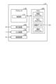
- FIG. 1 is a diagram showing a configuration of a communication system including a numerical controller according to a first embodiment
- FIG. FIG. 4 is a diagram showing a screen displayed by the numerical controller according to the first embodiment when selecting a machining program
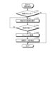
- FIG. 4 is a flowchart showing a processing procedure of processing executed by a mobile terminal included in the communication system according to the first embodiment
- 4 is a flowchart showing a processing procedure of processing executed by the numerical controller according to the first embodiment
- FIG. 2 shows a configuration of a communication system including a numerical control device according to a second embodiment
- FIG. 10 is a diagram showing a screen when editing a machining program, displayed by the numerical control device according to the second embodiment; 4 is a flow chart showing a processing procedure of processing executed by the numerical controller according to the second embodiment; FIG. 10 is a diagram showing a screen displayed by the numerical control device according to the third embodiment when the machine tool is in operation; FIG. 10 is a diagram showing a screen for associating image data with a machining program, displayed by the numerical controller according to the third embodiment; FIG. 10 is a flow chart showing a processing procedure of processing executed by a numerical control device according to a third embodiment; FIG. The figure which shows the structure of the communication system provided with the numerical control apparatus concerning Embodiment 4. FIG.
- FIG. 11 is a diagram showing a screen displayed by the numerical control device according to the fourth embodiment during a matching operation;
- FIG. FIG. 10 is a flow chart showing a processing procedure of processing executed by a numerical control device according to a fourth embodiment;
- FIG. FIG. 4 is a diagram showing a hardware configuration example for realizing the numerical controllers according to the first to fourth embodiments;
- FIG. 1 is a diagram showing a configuration of a communication system including a numerical control device according to Embodiment 1.
- the communication system 100A includes a numerical control (NC) device 1A and a mobile terminal 2 .
- NC numerical control
- the numerical controller 1A is a device that controls industrial machines such as machine tools, injection molding machines, electric discharge machines, and press machines.
- Examples of the mobile terminal 2 are smart phones, tablet PCs (Personal Computers), mobile phones, and the like.
- the industrial machine controlled by the numerical control device 1A is a machine tool that mainly performs metal processing
- the industrial machine controlled by the numerical control device 1A may be any machine.
- the numerical controller 1A is mounted, for example, on a machine tool such as a machining center or a lathe.
- the numerical controller 1A stores a machining program for machining metal.
- the numerical controller 1A analyzes the machining program and transmits the analysis result as a drive command to a drive section including motors that drive tools and workpieces (workpieces). Functions for sending commands to these drive units are omitted in FIG.
- the mobile terminal 2 is a terminal capable of capturing and transmitting an image.
- the numerical controller 1A has a communication section 11, a control section 12, storage sections 13, 14, and 15, which are a plurality of storage sections, an input section 16, and a display section 17.
- the mobile terminal 2 has a communication section 21 , an application 22 , a storage section 23 , a display section 24 and an imaging section 25 .
- the communication unit 21 is the first communication unit
- the communication unit 11 is the second communication unit.
- the storage units 13 to 15 are the first storage device
- the storage unit 23 is the second storage device.
- the communication unit 11 performs mutual data communication with an external device such as the mobile terminal 2 .
- the communication unit 11 included in the numerical control device 1A performs data communication with the communication unit 21 included in the mobile terminal 2 .
- the communication unit 11 receives, for example, image data (image data 231 to be described later) of a processed object sent from the communication unit 21 of the mobile terminal 2 .
- the communication unit 11 and the communication unit 21 perform wireless communication, for example, via a wireless LAN (Local Area Network), and the communication unit 11 can receive the image data 231 even from a location remote from the mobile terminal 2 .
- the communication means used by the communication units 11 and 21 is not limited to the wireless LAN.
- the communication units 11 and 21 may execute communication using a wired LAN, or may execute communication using a USB (Universal Serial Bus) cable, Bluetooth (registered trademark), infrared communication, or the like.
- the storage unit 13 has a machining program storage area 131 and an image storage area 132 .
- the storage unit 14 has a machining program storage area 141 and an image storage area 142 .
- the storage unit 15 has a machining program storage area 151 , an image storage area 152 and a selection program storage area 153 . Machining program storage areas 131, 141, and 151 are the first storage areas. Image storage areas 132, 142, and 152 are second storage areas. Further, in Embodiment 1, the selected program storage area 153 is the third storage area.
- the machining program storage areas 131, 141, and 151 are areas for storing the machining programs
- the image storage areas 132, 142, and 152 are areas for storing the image data 231 sent from the mobile terminal 2.
- the image data 231 is, for example, data representing a result of processing performed using a processing program. That is, the image data 231 is image data representing the shape of the processed object. This image data 231 is displayed together with the machining program when the user such as an operator selects the machining program next time, so that the user can visually confirm the machining program.
- the selected program storage area 153 stores information on the machining program specified by the user, that is, information indicating the machining program to be executed (hereinafter referred to as "selected program information").
- the selected program information is information indicating a state in which the machining program can be executed. Therefore, the state in which the selected program information is stored in the selected program storage area 153 is the state in which the machining program can be executed.
- the selected program information stored in the selected program storage area 153 may be any information as long as it can identify the machining program.
- An example of the selected program information stored in the selected program storage area 153 is the machining program name of the selected machining program.
- the selected program information may be the file name of the machining program.
- the storage units 13 to 15 are devices that can store data such as hard disks and non-volatile memories.
- the storage units 13 to 15 may be four or more.
- the storage unit 13 is a hard disk
- the storage unit 14 is an SD (Secure Digital) card
- the storage unit 15 is an internal memory.
- the input unit 16 receives information from outside the numerical control device 1A and inputs the information to the control unit 12 .
- the input unit 16 is composed of input means such as a keyboard, buttons, or a mouse.
- the input unit 16 accepts an input such as a command to the numerical control device 1A by the user, an NC program that is a machining program, parameters, and the like, and inputs them to the control unit 12 .
- the display unit 17 is configured by display means such as a liquid crystal display device.
- the display unit 17 displays the information processed by the control unit 12 on the display screen.
- the display unit 17 displays, for example, a machining program name, an image of a workpiece (an image corresponding to the image data 231), and the like.
- An example of the display unit 17 is a liquid crystal touch panel.
- the display section 17 is a liquid crystal touch panel, some functions of the input section 16 are arranged on the display section 17 .
- the control unit 12 controls the communication unit 11, the storage units 13 to 15, the input unit 16, and the display unit 17.
- the control unit 12 has a search unit 121 and a selection unit 122 .
- the search unit 121 searches for a storage unit for saving the image data 231 sent from the mobile terminal 2 . Specifically, the search unit 121 determines which storage unit stores the processing program corresponding to the selected program information stored in the selected program storage area 153, that is, the processing program corresponding to the image data 231. search for.
- the selection unit 122 selects the machining program to be executed from among the machining programs stored in the machining program storage areas 131, 141, 151 of the storage units 13, 14, 15.
- the machining program to be executed from now on is the machining program designated by the user.
- the selection unit 122 causes the selected program storage area 153 to store information indicating which machining program has been selected. That is, the selection unit 122 causes the selected program storage area 153 to store selected program information indicating the machining program specified by the user.
- the control unit 12 treats the file name of the image data 231 as the processing program name of the processing program used for processing. Set to the same name. Note that the file extension of the image data 231 and the file extension of the processing program are different.
- the communication unit 21 of the mobile terminal 2 performs data communication with an external device such as the numerical controller 1A.
- the application 22 is software that executes a function of providing the numerical control device 1A with image data 231 to be associated with the machining program.
- the application 22 has an application processing section 221 and an image conversion section 222 .
- the application processing unit 221 When the application processing unit 221 receives an imaging command from the user, it causes the imaging unit 25 to perform imaging.
- the image conversion unit 222 executes image conversion of the image data 231 . Specifically, the image conversion section 222 performs image conversion of the image data 231 so that the numerical control device 1A can perform data processing using the image data 231 .
- the storage unit 23 is composed of non-volatile memory such as a hard disk and SRAM (Static Random Access Memory).
- the storage unit 23 stores image data 231 of the image captured by the imaging unit 25 and the like.
- the display unit 24 is a display such as liquid crystal or organic EL (Electro Luminescence), and displays the state of the mobile terminal 2, images captured by the imaging unit 25, and the like. This allows the user to check the state of the mobile terminal 2, the image captured by the imaging unit 25, and the like.
- the mobile terminal 2 may have a touch panel. In this case, the user can operate the mobile terminal 2 with respect to the display unit 24 . If the mobile terminal 2 does not have a touch panel, the mobile terminal 2 has an operation section in addition to the display section 24 .
- the imaging unit 25 is a camera configured using a CCD (Charge Coupled Device), CMOS (Complementary Metal Oxide Semiconductor), or the like.
- the imaging unit 25 captures an image of a workpiece machined by the machine tool and acquires image data 231 corresponding to the image of the workpiece.
- the image captured by the mobile terminal 2 is associated with the processing program corresponding to the image by the numerical control device 1A, and when the user selects the processing program next time, the processing program is displayed by displaying the image. A process for visually confirming is explained.
- the user When starting machining by the machine tool, the user operates the input unit 16 and the display unit 17. That is, the user inputs a machining start command to the numerical controller 1A.
- the selection unit 122 of the control unit 12 selects the machining program specified by the user from among the machining programs stored in the machining program storage areas 131, 141, and 151 of the storage units 13 to 15, that is, the program to be executed from now. Select the machining program to be used.
- the machining program designated by the user is the first machining program.
- the control unit 12 reads out the selected machining program, and the selection unit 122 causes the selected program storage area 153 to store selected program information indicating which machining program is being selected.
- the machining program read by the control unit 12 is written in a main memory (not shown).
- a state in which the selected program storage area 153 stores selected program information is an executable state (search state) in which processing can be executed.
- search state an executable state
- the numerical controller 1A starts controlling the machine tool.
- the control unit 12 executes the machining program written in the main memory.
- the motor of the machine tool operates, and the machine tool starts machining metal or the like using the tool.
- the selected program storage area 153 continues to store the selected program information.
- the image of the processed object using the mobile terminal 2 is performed.
- the user uses the portable terminal 2 to capture an image of a workpiece as a result of machining in a state in which the machining program is executable, that is, in a state in which the selected program information is stored in the selected program storage area 153 .
- the mobile terminal 2 activates the application 22 that provides the numerical controller 1A with image data 231 to be associated with the processing program, and causes the display unit 24 to display the processing content of the application 22 .
- the application processing unit 221 of the application 22 becomes capable of capturing an image using the imaging unit 25 .
- the application processing unit 221 starts imaging using the imaging unit 25 .
- the application processing unit 221 causes the storage unit 23 to store the image data 231 of the image captured by the imaging unit 25 .
- the image conversion unit 222 of the application 22 converts the image data 231 into an image.
- Image conversion includes resizing an image and changing its format.
- the image conversion unit 222 reads format information 232 stored in the storage unit 23 and performs image conversion according to the format information 232 .
- the format information 232 is information specifying the size of the image after image conversion, the format of the image after image conversion, and the like.
- the format information 232 specifies the size of an image that can be displayed by the numerical controller 1A, the format that can be processed by the numerical controller 1A, and the like. Therefore, the image conversion unit 222 uses the format information 232 to convert the image data 231 into a format for displaying the image of the workpiece on the numerical control device 1A.
- the format information 232 stored in the storage unit 23 is stored in the application 22 in advance. This format information 232 is stored in the storage unit 23 of the mobile terminal 2 from the installation data when the mobile terminal 2 installs the application 22 .
- the image conversion unit 222 reads the image data 231 after image conversion from the storage unit 23 and stores it in a temporary storage area (not shown) that temporarily stores the data. After that, the application 22 causes the communication section 21 to transmit the image data 231 . As a result, the communication unit 21 reads out the image data 231 from the data temporary storage area and transmits the image data 231 to the communication unit 11 of the numerical controller 1A. Note that the number of pieces of image data 231 transmitted by the communication unit 21 for one processing (one processing program) is not limited to one, and may be plural.
- the numerical controller 1A saves the received image data 231 in a temporary storage area (not shown) that temporarily stores the data.
- the search unit 121 of the control unit 12 searches for a storage unit (storage destination) for storing the image data 231 stored in the temporary storage area. That is, the search unit 121 searches in which storage unit in the numerical controller 1A the machining program corresponding to the selected program information stored in the selected program storage area 153 is stored. For example, when the selected program information stored in the selected program storage area 153 is a program name, the search unit 121 searches the storage unit 13, the storage unit 14, and the storage unit 15 in order for the program name.
- the order (priority) of the storage units searched by the search unit 121 is determined in advance by the numerical control device 1A, for example. That is, the search unit 121 searches for machining programs in a predetermined order in a plurality of storage units. Note that the search unit 121 may search for a machining program according to the search order specified by the user for a plurality of storage units. In this case, the order in which the storage units are searched is determined by the user using a parameter or the like indicating the order of search. Thereby, the search unit 121 can improve the search speed. In addition, when different storage units store processing programs with the same program name but different contents, the user sets the order of the storage units to be searched so that the image data 231 can correspond to the processing program intended by the user. can be attached. As described above, the order of the storage units searched by the search unit 121 may be determined in advance by the numerical control device 1A, or may be determined by the user using a parameter or the like indicating the search order.
- the search unit 121 finds the storage destination of the corresponding machining program, that is, finds the machining program corresponding to the selected program information
- the search unit 121 saves the image data 231 in the image storage area of the same storage unit as the found machining program. .
- the search unit 121 stores the image data 231 in the image storage area 142 .
- the search unit 121 sets the file name of the image data 231 to the same name as the processing program name of the processing program and saves it in the storage unit 14 . This completes the correspondence between the image data 231 and the processing program in the communication system 100A.
- the numerical control device 1A automatically associates the image data 231 with the processing program. That is, the user who wants to make the correspondence selects a machining program to be used for machining the workpiece in front of the screen of the numerical controller 1A, and starts machining the workpiece. After the machining is completed, the portable terminal 2 takes an image of the workpiece while the machining program is still selected in the numerical controller 1A, and transmits image data 231 to the numerical controller 1A. Thereby, the numerical controller 1A associates the received image data 231 with the selected machining program used for machining.
- the numerical controller 1A associates the received image data 231 with the selected machining program used for machining, so the user does not need to select the machining program. Therefore, in the numerical control device 1A, the number of processing procedures for associating the image data 231 captured by the portable terminal 2 with the processing program is reduced. In addition, when the user associates the image data 231 with the processing program, erroneous association such as selection error of the processing program can be prevented.
- the data sent from the communication unit 21 of the mobile terminal 2 to the communication unit 11 of the numerical control device 1A is only image data, and the setting data and the like that are required in the conventional technology are unnecessary. Therefore, the communication system 100A can prevent the storage destination of the image data from being lost when the setting data cannot be received normally due to a communication error or the like, unlike the conventional technology.
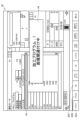
- FIG. 2 is a diagram showing a screen displayed by the numerical controller according to the first embodiment when selecting a machining program.
- the control unit 12 causes the display unit 17 to display a screen 41 for selecting a machining program.
- a screen 41 is displayed when a machining program is selected by the user.
- a list 31 of machining programs to be selected by the user is displayed. Also, on the screen 41, an image 32 of a workpiece corresponding to the machining program selected by the user is displayed. This image 32 is an image displayed using the image data 231 having the same file name as the processing program name of the processing program selected by the user.
- the selection unit 122 When the user operates the input unit 16 to select any machining program from the list 31 displayed on the screen 41, the selection unit 122 highlights the selected machining program. Further, the selection unit 122 searches the storage units 13 to 15 for the machining program selected by the user. In addition, the selection unit 122 causes the selected program storage area 153 to store the selected program information (for example, the name of the machining program) indicating the searched machining program, that is, the machining program to be executed from now on.
- the selected program information for example, the name of the machining program
- the search unit 121 retrieves the image data 231 having the same file name as the processing program name of the processing program selected by the user. Search from within. If there is image data 231 with the same name, the search unit 121 causes the display unit 17 to display it like an image 32 .
- the search unit 121 sets the search range for the image data 231 to the storage unit in which the processing program selected by the user is saved. , and may be extended to other storage units.
- FIG. 3 is a flowchart of a processing procedure of processing executed by a mobile terminal included in the communication system according to the first embodiment
- the mobile terminal 2 captures an image of the workpiece according to the user's operation. Specifically, the mobile terminal 2 activates the application 22 according to the user's operation. Furthermore, when the user performs an image capturing operation, the application processing unit 221 uses the image capturing unit 25 to perform image capturing.
- the application 22 determines whether or not imaging has been performed (step S101). If imaging has not been performed (step S ⁇ b>101 , No), the mobile terminal 2 terminates the process of transferring the image data 231 .
- step S101 Yes
- the application 22 stores the image data 231 of the image captured by the imaging unit 25 in the storage unit 23.
- the application 22 selects a device to which the image data 231 is to be transferred (step S102).
- a device to which the mobile terminal 2 transmits the image data 231 is a numerical control device.
- the application 22 selects, for example, a numerical controller with which communication has been established with the mobile terminal 2 or a numerical controller with which communication has been made in the past.
- the application 22 causes the display unit 24 to display numerical controllers with which communication has been established with the portable terminal 2, or numerical controllers with which communication has been established in the past, so that the user can select a numerical controller.
- the application 22 of Embodiment 1 selects the numerical controller 1A.
- step S103 the application 22 confirms whether or not the image data 231 can be transferred to the selected numerical controller 1A (step S103). If the selected numerical control device 1A is not in an executable state in which processing can be executed, that is, if transfer is not possible (step S103, No), the application 22 returns to the process of step S102. Further, if the selected numerical control device 1A is not equipped with a function for executing the correspondence between the image data 231 and the processing program, the application 22 determines that the transfer is impossible, and performs the processing of step S102. back to
- the image conversion unit 222 reads the format information 232 stored in the storage unit 23. Then, the image conversion unit 222 performs image conversion such as format conversion on the image data 231 according to the format information 232 (step S104). Thereafter, the application 22 transfers the image data 231 that has undergone image conversion from the communication section 21 to the numerical controller 1A (step S105).
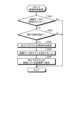
- FIG. 4 is a flowchart of a processing procedure of processing executed by the numerical controller according to the first embodiment
- the selection unit 122 selects the specified machining program based on this command. Read from the storage units 13-15. Specifically, the selection unit 122 reads the machining program specified by the user from among the machining programs stored in the machining program storage areas 131 , 141 , and 151 .
- the selection unit 122 causes the selected program storage area 153 of the storage unit 15 to store selected program information indicating which machining program is being selected.
- the numerical controller 1A becomes ready for processing.
- the machine tool starts machining according to the control by the controller 12 .
- the control unit 12 determines whether or not the image data 231 has been transferred from the mobile terminal 2 (step S201). When the machining using the machining program corresponding to the selected program information stored in the selected program storage area 153 is completed, image data 231 is sent from the mobile terminal 2 to the numerical controller 1A.
- the communication unit 11 of the numerical controller 1A receives the image data 231. If the image data 231 has not been transferred from the portable terminal 2 (step S201, No), the numerical controller 1A terminates the process of associating the image data 231 with the processing program.
- the search unit 121 determines whether or not it is in an executable state in which processing can be performed (step S202). If it is not in the executable state (step S202, No), the numerical controller 1A terminates the process of associating the image data 231 with the processing program. In this case, the numerical controller 1A may notify the portable terminal 2 that the image data 231 has not been saved.
- the search unit 121 searches for the storage location of the machining program corresponding to the selected program information stored in the selected program storage area 153 (step S203).
- the selected program information is information indicating a processing program corresponding to the image data 231 transferred from the mobile terminal 2 .
- the search unit 121 When the search unit 121 finds the storage location of the corresponding processing program, it saves the image data 231 in the image storage area of the same storage unit as the found processing program. In this case, the search unit 121 renames the file name of the image data 231 (step S204). Specifically, the search unit 121 rewrites the file name of the image data 231 to the same name as the processing program name of the processing program that found the storage destination. Then, the search unit 121 saves the image data 231 whose file name has been rewritten in the image storage area of the storage unit storing the processing program whose storage destination has been found (step S205). Thereby, the numerical controller 1A associates the image data 231 transferred from the portable terminal 2 with the processing program.
- the image data 231 associated by the numerical control device 1A is data representing the image of the workpiece that has been processed under the control of the numerical control device 1A.
- the machining program associated with the numerical controller 1A is the machining program used for control by the numerical controller 1A. Therefore, the numerical controller 1A can associate the machining program used for machining with the image data 231 of the workpiece machined using this machining program.
- the numerical controller 1A repeats the correspondence between the image data 231 and the processing program. As a result, image data 231 corresponding to the processing program is accumulated.
- the search unit 121 searches the image data 231 having the same file name as the processing program name of the processing program specified by the user from within the image storage area of the storage unit in which the processing program specified by the user is stored. do. If there is image data 231 with the same name, the search unit 121 causes the display unit 17 to display an image corresponding to the image data 231 .
- control unit 12 may create a data table showing the correspondence between the image data 231 and the processing program, and manage the correspondence between the image data 231 and the processing program using this data table.
- search unit 121 searches the image data 231 corresponding to the processing program using the data table.
- the numerical controller 1A executes the association process, so that the user can use the portable terminal 2 to search for the machining program. you don't have to. For this reason, even when images of a workpiece are repeatedly captured by repeated processing, the user does not need to search for a processing program associated with the image data 231 each time.
- the control unit 12 of the numerical controller 1A controls the machining of the workpiece using the machining program specified by the user among the machining programs. Then, when the image data 231 is sent from the portable terminal 2 in an executable state in which processing can be executed, the numerical control device 1A searches the storage units 13 to 15 for the processing program used for control, 2 is associated with the image data 231 sent from 2. Thereby, the communication system 100A can easily associate the image of the workpiece (image data 231) with the processing program.
- the numerical control device 1A causes the selected program storage area 153 to store the selected program information and at least one of the processing start time and the processing end time in association with each other, and the portable terminal 2 stores the image data 231 and the imaging time. may be linked and transmitted to the numerical controller 1A.
- the search unit 121 searches for a processing program whose processing start time or processing end time is before and closest to the imaging time, and associates it with the image data 231 .
- the communication system 100A can obtain the same effects as those described in the first embodiment.
- Embodiment 2 Next, Embodiment 2 will be described with reference to FIGS. 5 to 7.
- FIG. The numerical controller of Embodiment 2 associates the image data 231 with the machining program when the state of the numerical controller is the edit state of the machining program.
- the state of the numerical controller is the edit state of the machining program.
- there is an additional procedure for putting the machining program into an edit state immediately after machining but there is an advantage that the association work becomes explicit for the user.
- FIG. 5 is a diagram showing the configuration of a communication system provided with a numerical controller according to the second embodiment. 5 that achieve the same functions as those of the communication system 100A of the first embodiment shown in FIG. 1 are denoted by the same reference numerals, and overlapping descriptions are omitted.
- the communication system 100B includes a numerical control device 1B instead of the numerical control device 1A compared to the communication system 100A. That is, the communication system 100B includes a numerical control device 1B and a mobile terminal 2.
- the numerical control device 1B differs from the numerical control device 1A in the storage areas included in the storage unit 15. Specifically, the storage unit 15 of the numerical controller 1B has an edit program storage area 154 instead of the selected program storage area 153, as compared with the storage unit 15 of the numerical controller 1A. As a result, the storage unit 15 of the numerical controller 1B stores information of the machining program being edited (hereinafter referred to as edited program information) instead of the selected program information, compared to the storage unit 15 of the numerical controller 1A. do.
- the edited program information is information indicating a state in which the machining program is edited. Therefore, the state in which the editing program information is stored in the editing program storage area 154 is the state in which the machining program is being edited.
- the editing program storage area 154 is the third storage area.
- the editing program information stored in the editing program storage area 154 may be any information as long as it can identify the machining program.
- An example of the editing program information stored in the editing program storage area 154 is the machining program name of the machining program being edited.
- the editing program information may be the file name of the machining program being edited.
- the image captured by the portable terminal 2 is associated with the processing program corresponding to the image by the numerical control device 1B, and when the user selects the processing program next time, the image is displayed so that the processing program can be changed. A process for visually confirming is explained.
- FIG. 6 is a diagram showing a screen displayed by the numerical controller according to the second embodiment when editing a machining program.
- a screen 42 is displayed when the machining program can be edited by the user.
- the user can edit the machining program by operating the keyboard on the input unit 16 or the like while confirming the displayed machining program.
- FIG. 6 shows a case where the machining program displayed on the editing screen 51 is the machining program 52 . That is, the screen 42 shown in FIG. 6 is in a state in which the machining program 52 can be edited.
- a message 53 indicating that the machining program 52 is being edited is displayed. This allows the user to check whether the machining program 52 is in the edit state.
- the user selects a desired machining program by a method similar to that described in Embodiment 1.
- the control unit 12 reads out the selected machining program and writes it into the main memory.
- the motor of the machine tool is activated, and the machine tool starts machining metal or the like using the tool.
- the control unit 12 causes the display unit 17 to display a screen 42 to enter the state of editing the processing program.
- the selection unit 122 searches the storage units 13 to 15 for the machining program selected by the user.
- the selection unit 122 causes the editing program storage area 154 to store the editing program information indicating the searched machining program, that is, the machining program used for machining. That is, the selection unit 122 causes the editing program storage area 154 to store the machining program in the editing state.
- the mobile terminal 2 captures an image of the workpiece after machining while the machining program is being edited, ie, the machining program is stored in the editing program storage area 154 . Thereafter, the portable terminal 2 transfers the image data 231 to the numerical controller 1B.
- the numerical controller 1B associates the image data 231 with the machining program being edited by the same method as the numerical controller 1A. Then, when the user selects a new machining program, the numerical controller 1B displays an image of the image data 231 corresponding to the machining program in the same manner as the numerical controller 1A.
- the method of associating the image data 231 with the machining program and the method of visually confirming the machining program using the image data 231 by the numerical controller 1B are the same as those of the numerical controller 1A.
- the processing procedure of the processing executed by the mobile terminal 2 is the same as in the first embodiment. That is, in the second embodiment, as in the first embodiment, the mobile terminal 2 executes processing according to the processing procedure shown in FIG.
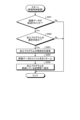
- FIG. 7 is a flowchart of a processing procedure of processing executed by the numerical controller according to the second embodiment
- the numerical controller 1B executes the process of step S302 instead of the process of step S202 in FIG. 4, compared to the process executed by the numerical controller 1A. That is, when the image data 231 is transferred from the portable terminal 2 (step S201, Yes), the numerical control device 1B determines whether the search unit 121 is in the editing state of the machining program (step S302). . If it is not in the editing state (step S302, No), the numerical controller 1B ends the process of associating the image data 231 with the processing program. In this case, the numerical controller 1B may notify the portable terminal 2 that the image data 231 has not been saved.
- step S302, Yes the numerical controller 1B executes the processes of steps S203 to S205 described in FIG.
- the numerical controller 1B stores the processing program used for control from the storage units 13 to 15. It is searched and associated with the image data 231 sent from the mobile terminal 2 .
- the communication system 100B can easily associate the image of the workpiece with the processing program, like the communication system 100A.
- the numerical control device 1B causes the editing program storage area 154 to save the editing program information and at least one of the editing start time and the editing end time in association with each other, and the portable terminal 2 stores the image data 231 and the imaging time. may be linked and transmitted to the numerical controller 1B.
- the search unit 121 searches for a processing program whose edit start time or edit end time is closest to the imaging time, and associates it with the image data 231 .
- the communication system 100B can obtain the same effects as those described in the second embodiment.
- Embodiment 3 Next, Embodiment 3 will be described with reference to FIGS. 8 to 10.
- FIG. The numerical controller of Embodiment 3 associates the image data 231 with the machining program when the state of the numerical controller is the machining program selection state. That is, when the user operates the numerical controller to select a machining program to be associated with the image data 231, the numerical controller associates the image data 231 with the machining program.
- the user's operating procedure is the same as in the second embodiment.
- a numerical controller 1A similar to that of the first embodiment is also used in the third embodiment. That is, the configuration of the numerical controller 1A of Embodiment 3 is the configuration shown in FIG.
- the image captured by the mobile terminal 2 is associated with the processing program corresponding to the image by the numerical control device 1A, and when the user selects the processing program next time, the processing program is displayed by displaying the image. A process for visually confirming is explained.
- the user selects a desired machining program for the numerical controller 1A of the third embodiment in the same manner as the method described in the first embodiment.
- the control unit 12 causes the display unit 17 to display a screen showing information regarding the operation of the machine tool during machining of the workpiece.
- FIG. 8 is a diagram showing a screen displayed by the numerical controller according to the third embodiment when the machine tool is in operation.
- the screen 43 is a screen that displays information during operation of the machine tool.
- the control unit 12 continues to display the screen 43 during operation of the machine tool even after the machining is completed.
- An image-related menu button 61 is displayed on the screen 43 .
- the image-related menu button 61 is a button for displaying a screen (screen 44 described later) for associating the image data 231 with the processing program when pressed by the user.
- FIG. 9 is a diagram showing a screen for associating image data with a processing program, displayed by the numerical controller according to the third embodiment.
- selection buttons 62A-62C for selecting the storage units 13-15 are displayed.
- Selection button 62A is a button corresponding to storage unit 13
- selection button 62B is a button corresponding to storage unit 14
- selection button 62C is a button corresponding to storage unit 15 .
- FIG. 9 shows a case where storage units 13 and 14 are memories and storage unit 15 is a hard disk.
- the control unit 12 selects the storage unit 13.
- the control unit 12 selects the storage unit 14 by the user pressing the selection button 62B.
- the control unit 12 selects the storage unit 15 when the selection button 62C is pressed by the user.
- FIG. 9 shows a state in which the selection button 62A is pressed.
- the user After the user presses the selection button 62A, the user operates the keyboard or the like to press the selection command button 63 for commanding the selection state of the machining program, and then presses the determination button (not shown).
- the control unit 12 may cause the display unit 17 to display a message 64 indicating that the image data 231 is being associated with the processing program.
- the selection unit 122 of the numerical controller 1A causes the selected program storage area 153 to store information indicating which machining program has been selected (hereinafter referred to as selection state information).
- the selection state information is information indicating the state in which the machining program is selected. Therefore, the state in which the selection state information is stored in the selection program storage area 153 is the state in which the machining program is selected.
- the mobile terminal 2 captures an image of the workpiece after machining while the machining program is selected, that is, the selection status information is stored in the selected program storage area 153 . Thereafter, the portable terminal 2 transfers the image data 231 to the numerical controller 1A.
- Numerical control device 1A associates image data 231 with the selected machining program by a method similar to that described in the first embodiment. Then, when the user selects a new machining program, the numerical controller 1A displays an image of the image data 231 corresponding to the machining program by the same method as described in the first embodiment.
- the method of associating the image data 231 with the processing program and the method of visually confirming the processing program using the image data 231 in the third embodiment are the same as in the first embodiment.
- the processing procedure of the processing executed by the mobile terminal 2 is the same as in the first embodiment. That is, in the third embodiment, as in the first embodiment, the mobile terminal 2 executes processing according to the processing procedure shown in FIG.
- FIG. 10 is a flowchart of a processing procedure of processing executed by the numerical controller according to the third embodiment.
- the numerical control apparatus 1A of Embodiment 3 executes the process of Step S402 instead of the process of Step S202 in FIG. That is, when the image data 231 is transferred from the portable terminal 2 (step S201, Yes), the numerical controller 1A of the third embodiment determines whether the search unit 121 is in the machining program selection state. (step S402). If it is not in the selected state (step S402, No), the numerical controller 1A terminates the process of associating the image data 231 with the processing program. In this case, the numerical controller 1A may notify the portable terminal 2 that the image data 231 has not been saved.
- step S402 If it is in the selected state (step S402, Yes), the numerical controller 1A executes the processes of steps S203 to S205 described with reference to FIG.
- the numerical controller 1A when the image data 231 is sent from the portable terminal 2 while the processing program is selected, stores the processing program used for control from the storage units 13 to 15. It is searched and associated with the image data 231 sent from the mobile terminal 2 . As a result, the numerical controller 1A can easily associate the image of the workpiece with the machining program, as in the first embodiment.
- Embodiment 4 When operated by the user, the numerical controller of Embodiment 4 associates the image data 231 with the processing program according to the operation.
- the fourth embodiment since the association is executed according to the user's operation, unlike the first to third embodiments, confirmation of the state of the numerical controllers 1A and 1B and setting to the numerical controllers 1A and 1B in advance are required. becomes unnecessary. Therefore, even if the numerical controllers 1A and 1B are not in the state described in the first to third embodiments, there is an advantage that the image data 231 can be associated with the machining program.
- FIG. 11 is a diagram showing the configuration of a communication system provided with a numerical controller according to the fourth embodiment. Among the constituent elements in FIG. 11, the constituent elements that achieve the same functions as those of the communication system 100A of Embodiment 1 shown in FIG.
- the communication system 100C includes a numerical control device 1C instead of the numerical control device 1A, as compared with the communication system 100A. That is, the communication system 100C includes a numerical control device 1C and a mobile terminal 2.
- the numerical control device 1C differs from the numerical control device 1A in the storage areas included in the storage unit 15 .
- the storage unit 15 of the numerical control device 1C has a transfer image storage area 155 instead of the selected program storage area 153 compared to the storage unit 15 of the numerical control apparatus 1A.
- the storage unit 15 of the numerical control device 1C stores the image data 231 transferred from the portable terminal 2 instead of the selected program information, as compared with the storage unit 15 of the numerical control device 1A.
- the control section 12 does not have the searching section 121 as compared with the numerical control device 1A.
- the image captured by the portable terminal 2 is associated with the processing program corresponding to the image by the numerical control device 1C, and when the user selects the processing program next time, the image is displayed to display the processing program. A process for visually confirming is explained.
- the numerical controller 1C associates the image data 231 with the processing program regardless of the state of the numerical controller 1C. Further, the numerical controller 1C may associate the image data 231 with the processing program in a state different from the states of the numerical controllers 1A and 1B described in the first to third embodiments. That is, the numerical control device 1C associates the image data 231 with the machining program when none of the executable state in which machining can be executed, the editing state of the machining program, and the selection state of the machining program by user operation is performed.
- the mobile terminal 2 takes an image of the workpiece.
- the mobile terminal 2 converts the image data 231 of the imaged image according to the format information 232, and transfers it to the numerical controller 1C.
- the process of the mobile terminal 2 capturing an image of the workpiece and transferring it to the numerical control device 1C is the same as that of the numerical control device 1A of the first embodiment.
- the numerical controller 1C stores the image data 231 received by the communication unit 11 in the transfer image storage area 155. At that time, in consideration of storing a plurality of image data 231, the numerical controller 1C sets a file name that does not have the same file name as the other image data 231 using numbers starting from 1, random character strings, and the like. Save the image data 231 as a file.
- the numerical control device 1C After the numerical control device 1C saves one or more image data 231 in one or more transfer image storage areas 155, the user performs an association operation. A user performs a matching operation by operating the numerical controller 1C.
- the user operates the numerical control device 1C from the input section 16 using a keyboard or the like while confirming the screen displayed on the display section 17 .
- a screen displayed by the display unit 17 when the user performs the association operation will be described.
- FIG. 12 is a diagram showing a screen displayed by the numerical control device according to the fourth embodiment during a matching operation.
- Selection buttons 62A to 62C for selecting the storage units 13 to 15 are displayed on the screen 45 displayed by the display unit 17 when the user performs the association operation.
- the screen 45 also displays an image data selection button 94 for instructing the selection state of the image data 231 .
- the image data selection button 94 is a button for selecting the image data 231 desired by the user from among the plurality of image data 231 . Therefore, one image data selection button 94 is associated with one image data 231 .
- FIG. 12 shows a state in which the selection button 62A is pressed. After the user presses the selection button 62A, the user operates the keyboard or the like to press the selection command button 63 for commanding the selection state of the machining program, and then presses the determination button (not shown). Sets the selected machining program to the selected state.
- the control unit 12 puts the selected image data 231 into the selection state.
- control unit 12 associates the selected processing program with the selected image data 231 . That is, the control unit 12 associates the processing program corresponding to the selection command button 63 with the image data 231 corresponding to the image data selection button 94 .
- control unit 12 associates the processing program in the selected state with the image data 231 in the selected state. good too. That is, either the image data 231 or the processing program may be selected first.
- control unit 12 may cause the screen 45 to display in which state the procedure included in the association operation is.
- the user is notified of the state of the procedure included in the association operation by displaying it on the screen 45 using a comment column 95 or the like.
- the comment column 95 for example, "selecting a machining program” indicating that the machining program is selected, "selecting image data” indicating that the image data 231 is selected, and indicating that the association operation is completed. "Associating operation completed” or the like is displayed.
- FIG. 12 shows a case where "selecting a machining program" is displayed in the comment column 95 indicating the state of the procedure included in the association operation.
- the control unit 12 saves the image data 231 associated with the image data 231 in the storage unit. Specifically, the control unit 12 transfers the image data 231 stored in the transfer image storage area 155 and selected by the association operation to the storage in which the processing program selected by the association operation is saved. image storage area. At that time, the control unit 12 changes the file name of the image data 231 to the same name as the processing program name, and saves the image data 231 in the storage unit storing the processing program in the same manner as in the method described in the first embodiment. to save.
- the processing procedure of the processing executed by the mobile terminal 2 is the same as in the first embodiment. That is, in the fourth embodiment, as in the first embodiment, the mobile terminal 2 executes processing according to the processing procedure shown in FIG. However, in the fourth embodiment, the condition for checking whether or not transfer is possible in step S102 does not include the state of the numerical controller 1C. The portable terminal 2 determines whether or not the transfer is possible by whether or not the numerical control device 1C is equipped with a matching function.
- FIG. 13 is a flowchart of a processing procedure of processing executed by the numerical controller according to the fourth embodiment.
- the control unit 12 determines whether or not the image data 231 transferred from the portable terminal 2 is stored in the transfer image storage area 155 (step S501). If the transferred image data 231 is not saved (step S501, No), the numerical controller 1C terminates the process of associating the image data 231 with the processing program.
- step S501 Yes
- the control unit 12 selects a processing program to be associated according to the instruction from the user (step S502). Further, the control unit 12 selects the image data 231 to be associated according to the instruction from the user (step S503).
- the numerical controller 1C executes the processes of steps S204 and S205 described with reference to FIG. Note that the numerical controller 1C may execute either the process of step S502 or the process of step S503 first.
- the numerical controller 1C associates the image data 231 with the selected machining program according to the user's operation regardless of the state of the numerical controller 1C. Similarly, the image of the workpiece and the machining program can be easily associated with each other.
- FIG. 14 is a diagram showing a hardware configuration example for realizing the numerical controllers according to the first to fourth embodiments. Since the numerical controllers 1A to 1C have the same hardware configuration, the hardware configuration of the numerical controller 1A will be described here.
- the numerical controller 1A can be realized by the processor 100, the memory 200, the input device 300, the display device 400, and the communication device 500.
- An example of the processor 100 is a CPU (Central Processing Unit, central processing unit, processing unit, arithmetic unit, microprocessor, microcomputer, DSP (Digital Signal Processor)) or system LSI (Large Scale Integration).
- Examples of the memory 200 are RAM (Random Access Memory) and ROM (Read Only Memory).
- the numerical controller 1A is implemented by the processor 100 reading and executing a computer-executable control program for executing the operations of the numerical controller 1A stored in the memory 200.
- a control program which is a program for executing the operation of the numerical controller 1A, can be said to cause a computer to execute the procedure or method of the numerical controller 1A.
- the control program executed by the numerical controller 1A has a module configuration including the control unit 12, which are loaded onto the main memory and generated on the main memory.
- the input device 300 receives commands from the user and sends them to the processor 100 .
- the input device 300 also receives a machining program from an external device and sends it to the memory 200 .
- the input device 300 corresponds to the input section 16 .
- the memory 200 includes storage units 13 to 15 and the like.
- the memory 200 stores control programs, processing programs, image data 231, selection programs, and the like.
- the control program, processing program, image data 231 and selection program are sent to the processor 100 .
- the memory 200 is also used as a temporary storage area when the processor 100 executes various processes.
- the communication device 500 executes communication with the mobile terminal 2 and the like.
- a communication device 500 corresponds to the communication unit 11 .
- the display device 400 displays a screen 41 and the like.
- a display device 400 corresponds to the display section 17 .
- the control program may be stored in a computer-readable storage medium in an installable or executable format and provided as a computer program product. Also, the control program may be provided to the numerical controller 1A via a network such as the Internet. It should be noted that the functions of the numerical controller 1A may be partly realized by dedicated hardware such as a dedicated circuit, and partly realized by software or firmware.
- 1A to 1C numerical controller 2 mobile terminal, 11, 21 communication unit, 12 control unit, 13 to 15, 23 storage unit, 16 input unit, 17, 24 display unit, 22 application, 25 imaging unit, 31 list, 32 image, 41 to 45 screen, 51 editing screen, 52 processing program, 53, 64 message, 61 image related menu button, 62A to 62C selection button, 63 selection command button, 94 image data selection button, 95 comment field, 100 processor , 100A to 100C communication system, 121 search unit, 122 selection unit, 131, 141, 151 machining program storage area, 132, 142, 152 image storage area, 153 selection program storage area, 154 editing program storage area, 155 transfer image storage Area, 200 memory, 221 application processing unit, 222 image conversion unit, 231 image data, 232 format information, 300 input device, 400 display device, 500 communication device.
Landscapes
- Engineering & Computer Science (AREA)
- Human Computer Interaction (AREA)
- Manufacturing & Machinery (AREA)
- Physics & Mathematics (AREA)
- General Physics & Mathematics (AREA)
- Automation & Control Theory (AREA)
- Numerical Control (AREA)
Abstract
Provided is a communication system (100A) comprising a numerical control device (1A) for controlling an industrial machine by using machining programs and a mobile terminal (2), the numerical control device and the mobile terminal communicating with each other, the mobile terminal comprising: an imaging unit (25) that acquires image data obtained by imaging a workpiece machined by using a first machining program specified by a user from among the machining programs; and a communication unit (21) that transmits the image data to the numerical control device, the numerical control device comprising: a communication unit (11) that receives the image data; storage units (13 to 15) that store the machining programs including the first machining program; and a control unit (12) that retrieves the first machining program from the storage unit and associates the first machining program with the image data.
Description
本開示は、携帯端末によって撮像された画像の通信を行う通信システムおよび数値制御装置に関する。
The present disclosure relates to a communication system and a numerical controller for communicating images captured by mobile terminals.
産業機械が加工した加工物の画像を携帯端末が撮像し、産業機械の制御装置が携帯端末から画像を受信して加工プログラムと同時に表示する通信システムがある。この通信システムでは、制御装置が、画像と加工プログラムとを対応付けて記憶しておき、ユーザが加工プログラムを選択する際に画像と加工プログラムとを同時に表示している。これにより、ユーザは、加工プログラムを選択する際に、加工プログラムに対応する加工物の画像を視覚的に確認することが可能となる。
There is a communication system in which a mobile terminal captures an image of a workpiece processed by an industrial machine, and the controller of the industrial machine receives the image from the mobile terminal and displays it simultaneously with the machining program. In this communication system, the control device stores an image and a processing program in association with each other, and displays the image and the processing program at the same time when the user selects the processing program. This enables the user to visually confirm the image of the workpiece corresponding to the machining program when selecting the machining program.
制御装置が加工物の画像データを使用する場合、制御装置は、画像データを使用可能とするために、画像データに対して形式の変更、サイズの変更といった設定登録を行うが、この設定登録の作業が煩雑である。
When the control device uses the image data of the workpiece, the control device performs setting registration such as format change and size change for the image data in order to make the image data usable. Work is complicated.
特許文献1に記載の通信システムは、携帯端末と制御装置との間で相互通信を行うとともに、産業機械の制御装置側で画像データを使用することができるよう自動的に画像の設定を行っている。この通信システムでは、携帯端末が、制御装置に応じた画像変換を行って変換画像データを作成するとともに制御装置側で利用する設定データを作成し、その両データを制御装置に送信している。制御装置は、受信した設定データを参照することで画像データを表示している。
The communication system described in Patent Document 1 performs mutual communication between the mobile terminal and the control device, and automatically sets the image so that the image data can be used on the control device side of the industrial machine. there is In this communication system, the mobile terminal performs image conversion according to the control device to create converted image data, creates setting data to be used by the control device, and transmits both data to the control device. The control device displays the image data by referring to the received setting data.
しかしながら、上記特許文献1の技術では、加工物の画像を加工プログラムに対応付ける場合、産業機械が加工を実行して、携帯端末が加工結果である加工物を撮像し、ユーザが携帯端末を用いて制御装置から加工プログラムを探して設定するという操作が必要となる。このように、上記特許文献1の技術では、加工物を撮像するたびにユーザが加工プログラムを選択する必要があり加工物の画像を加工プログラムに対応付ける際に手間を要するという問題があった。
However, in the technique of Patent Document 1, when an image of a workpiece is associated with a machining program, an industrial machine executes machining, a mobile terminal captures an image of the workpiece as a machining result, and a user uses the mobile terminal to capture an image of the workpiece. An operation of searching for a machining program from the control device and setting it is required. As described above, the technique of Patent Literature 1 has a problem that the user needs to select a processing program every time an object to be processed is imaged, and it takes time and effort to associate the image of the object to be processed with the processing program.
本開示は、上記に鑑みてなされたものであって、加工物の画像と加工プログラムとを容易に対応付けることができる通信システムを得ることを目的とする。
The present disclosure has been made in view of the above, and aims to obtain a communication system that can easily associate an image of a workpiece with a processing program.
上述した課題を解決し、目的を達成するために、本開示は、加工プログラムを用いて産業機械を制御する数値制御装置と携帯端末とを備え、携帯端末と数値制御装置との間で通信を行う通信システムであって、携帯端末は、加工プログラムのうちユーザにより指定された第1の加工プログラムを用いて加工された加工物を撮像して画像データを取得する撮像部を有する。また、携帯端末は、画像データを数値制御装置へ送信する第1の通信部を有する。数値制御装置は、第1の通信部から送られてくる画像データを受信する第2の通信部と、第1の加工プログラムを含む加工プログラムを記憶する第1の記憶装置とを有する。また、数値制御装置は、第1の加工プログラムを第1の記憶装置から検索して、第1の加工プログラムと画像データとを対応付ける制御部とを有する。
In order to solve the above-described problems and achieve the object, the present disclosure includes a numerical controller and a mobile terminal that control an industrial machine using a machining program, and communicates between the mobile terminal and the numerical controller. A mobile terminal has an imaging unit that captures an image of a workpiece processed using a first processing program specified by a user among processing programs to obtain image data. Also, the portable terminal has a first communication unit that transmits image data to the numerical controller. The numerical controller has a second communication section for receiving image data sent from the first communication section, and a first storage device for storing a machining program including a first machining program. The numerical controller also has a control unit that retrieves the first machining program from the first storage device and associates the first machining program with the image data.
本開示にかかる通信システムは、加工物の画像と加工プログラムとを容易に対応付けることができるという効果を奏する。
The communication system according to the present disclosure has the effect of being able to easily associate images of processed objects with processing programs.
以下に、本開示の実施の形態にかかる通信システムおよび数値制御装置を図面に基づいて詳細に説明する。
A communication system and a numerical control device according to embodiments of the present disclosure will be described in detail below with reference to the drawings.
実施の形態1.
図1は、実施の形態1にかかる数値制御装置を備える通信システムの構成を示す図である。通信システム100Aは、数値制御(NC:Numerical Control)装置1Aと、携帯端末2とを備えている。Embodiment 1.
FIG. 1 is a diagram showing a configuration of a communication system including a numerical control device according toEmbodiment 1. FIG. The communication system 100A includes a numerical control (NC) device 1A and a mobile terminal 2 .
図1は、実施の形態1にかかる数値制御装置を備える通信システムの構成を示す図である。通信システム100Aは、数値制御(NC:Numerical Control)装置1Aと、携帯端末2とを備えている。
FIG. 1 is a diagram showing a configuration of a communication system including a numerical control device according to
数値制御装置1Aは、工作機械、射出成型機、放電加工機、プレス加工機などの産業機械を制御する装置である。携帯端末2の例は、スマートフォン、タブレットPC(Personal Computer)、携帯電話などである。
The numerical controller 1A is a device that controls industrial machines such as machine tools, injection molding machines, electric discharge machines, and press machines. Examples of the mobile terminal 2 are smart phones, tablet PCs (Personal Computers), mobile phones, and the like.
なお、以下では、数値制御装置1Aが制御する産業機械が主に金属加工をする工作機械である場合について説明するが、数値制御装置1Aが制御する産業機械は何れの機械であってもよい。数値制御装置1Aは、例えば、マシニングセンタ、旋盤などの工作機械等に搭載される。
Although a case where the industrial machine controlled by the numerical control device 1A is a machine tool that mainly performs metal processing will be described below, the industrial machine controlled by the numerical control device 1A may be any machine. The numerical controller 1A is mounted, for example, on a machine tool such as a machining center or a lathe.
数値制御装置1Aは、金属を加工するための加工プログラムを記憶している。数値制御装置1Aは、加工プログラムを解析し、工具および加工物(加工ワーク)を駆動するモータを含む駆動部に、解析結果を駆動指令として送信する。これら駆動部に対する指令を送るための機能については、図1では省略している。携帯端末2は、画像を撮像して送信できる端末である。
The numerical controller 1A stores a machining program for machining metal. The numerical controller 1A analyzes the machining program and transmits the analysis result as a drive command to a drive section including motors that drive tools and workpieces (workpieces). Functions for sending commands to these drive units are omitted in FIG. The mobile terminal 2 is a terminal capable of capturing and transmitting an image.
数値制御装置1Aは、通信部11と、制御部12と、複数の記憶部である記憶部13,14,15と、入力部16と、表示部17とを有している。携帯端末2は、通信部21と、アプリケーション22と、記憶部23と、表示部24と、撮像部25とを有している。通信部21が第1の通信部であり、通信部11が第2の通信部である。記憶部13~15が第1の記憶装置であり、記憶部23が、第2の記憶装置である。
The numerical controller 1A has a communication section 11, a control section 12, storage sections 13, 14, and 15, which are a plurality of storage sections, an input section 16, and a display section 17. The mobile terminal 2 has a communication section 21 , an application 22 , a storage section 23 , a display section 24 and an imaging section 25 . The communication unit 21 is the first communication unit, and the communication unit 11 is the second communication unit. The storage units 13 to 15 are the first storage device, and the storage unit 23 is the second storage device.
通信部11は、携帯端末2といった外部機器との間でデータの相互通信を行う。通信システム100Aでは、数値制御装置1Aが備える通信部11は、携帯端末2が備える通信部21との間でデータ通信を行う。通信部11は、例えば、携帯端末2の通信部21から送られてくる加工物の画像データ(後述する画像データ231)を受信する。
The communication unit 11 performs mutual data communication with an external device such as the mobile terminal 2 . In the communication system 100A, the communication unit 11 included in the numerical control device 1A performs data communication with the communication unit 21 included in the mobile terminal 2 . The communication unit 11 receives, for example, image data (image data 231 to be described later) of a processed object sent from the communication unit 21 of the mobile terminal 2 .
通信部11と通信部21とは、例えば無線LAN(Local Area Network)で無線通信を行っており、通信部11は、携帯端末2から離れた場所からでも画像データ231を受信することができる。なお、通信部11,21が用いる通信手段は無線LANに限らない。通信部11,21は、有線LANを用いて通信を実行してもよいし、USB(Universal Serial Bus)ケーブル、Bluetooth(登録商標)、赤外線通信などを用いて通信を実行してもよい。
The communication unit 11 and the communication unit 21 perform wireless communication, for example, via a wireless LAN (Local Area Network), and the communication unit 11 can receive the image data 231 even from a location remote from the mobile terminal 2 . Note that the communication means used by the communication units 11 and 21 is not limited to the wireless LAN. The communication units 11 and 21 may execute communication using a wired LAN, or may execute communication using a USB (Universal Serial Bus) cable, Bluetooth (registered trademark), infrared communication, or the like.
記憶部13は、加工プログラム記憶領域131と、画像記憶領域132とを有している。記憶部14は、加工プログラム記憶領域141と、画像記憶領域142とを有している。記憶部15は、加工プログラム記憶領域151と、画像記憶領域152と、選択プログラム記憶領域153とを有している。加工プログラム記憶領域131,141,151が、第1の記憶領域である。画像記憶領域132,142,152が、第2の記憶領域である。また、実施の形態1では、選択プログラム記憶領域153が、第3の記憶領域である。
The storage unit 13 has a machining program storage area 131 and an image storage area 132 . The storage unit 14 has a machining program storage area 141 and an image storage area 142 . The storage unit 15 has a machining program storage area 151 , an image storage area 152 and a selection program storage area 153 . Machining program storage areas 131, 141, and 151 are the first storage areas. Image storage areas 132, 142, and 152 are second storage areas. Further, in Embodiment 1, the selected program storage area 153 is the third storage area.
加工プログラム記憶領域131,141,151は、加工プログラムを記憶する領域であり、画像記憶領域132,142,152は、携帯端末2から送られてきた画像データ231を記憶する領域である。画像データ231は、例えば加工プログラムを用いて加工が行われた加工結果を示すデータである。すなわち、画像データ231は、加工後の加工物の形状を示す画像のデータである。この画像データ231は、次にオペレータといったユーザが加工プログラムを選択する際に、加工プログラムと同時に表示されることで、ユーザが加工プログラムを視覚的に確認することが可能となる。
The machining program storage areas 131, 141, and 151 are areas for storing the machining programs, and the image storage areas 132, 142, and 152 are areas for storing the image data 231 sent from the mobile terminal 2. The image data 231 is, for example, data representing a result of processing performed using a processing program. That is, the image data 231 is image data representing the shape of the processed object. This image data 231 is displayed together with the machining program when the user such as an operator selects the machining program next time, so that the user can visually confirm the machining program.
選択プログラム記憶領域153は、ユーザによって指定された加工プログラムの情報、すなわち、これから実行される加工プログラムを示す情報(以下、選択プログラム情報という)を記憶する。選択プログラム情報は、加工プログラムを実行可能な状態を示す情報である。したがって、選択プログラム情報が選択プログラム記憶領域153で記憶されている状態は、加工プログラムを実行可能な状態である。
The selected program storage area 153 stores information on the machining program specified by the user, that is, information indicating the machining program to be executed (hereinafter referred to as "selected program information"). The selected program information is information indicating a state in which the machining program can be executed. Therefore, the state in which the selected program information is stored in the selected program storage area 153 is the state in which the machining program can be executed.
選択プログラム記憶領域153が記憶しておく選択プログラム情報は、加工プログラムを識別できる情報であれば何れの情報であってもよい。選択プログラム記憶領域153が記憶しておく選択プログラム情報の例は、選択された加工プログラムの加工プログラム名である。なお、選択プログラム情報は、加工プログラムのファイル名であってもよい。
The selected program information stored in the selected program storage area 153 may be any information as long as it can identify the machining program. An example of the selected program information stored in the selected program storage area 153 is the machining program name of the selected machining program. The selected program information may be the file name of the machining program.
記憶部13~15は、ハードディスク、不揮発性メモリなどのデータを保存することができる装置である。実施の形態1では、数値制御装置1Aが3つの記憶部、すなわち記憶部13~15を備えている場合について説明するが、数値制御装置1Aが備える記憶部は、1つまたは2つであってもよいし、4つ以上であってもよい。例えば、記憶部13はハードディスクであり、記憶部14はSD(Secure Digital)カードであり、記憶部15は内部メモリである。
The storage units 13 to 15 are devices that can store data such as hard disks and non-volatile memories. In Embodiment 1, the case where the numerical control device 1A includes three storage units, that is, the storage units 13 to 15 will be described. may be four or more. For example, the storage unit 13 is a hard disk, the storage unit 14 is an SD (Secure Digital) card, and the storage unit 15 is an internal memory.
入力部16は、数値制御装置1Aの外部から情報を受付けて制御部12に情報を入力する。入力部16は、キーボード、ボタン、またはマウスなどの入力手段によって構成されている。入力部16は、ユーザによる数値制御装置1Aに対するコマンドなどの入力、加工プログラムであるNCプログラム、パラメータなどを受付けて制御部12に入力する。
The input unit 16 receives information from outside the numerical control device 1A and inputs the information to the control unit 12 . The input unit 16 is composed of input means such as a keyboard, buttons, or a mouse. The input unit 16 accepts an input such as a command to the numerical control device 1A by the user, an NC program that is a machining program, parameters, and the like, and inputs them to the control unit 12 .
表示部17は、液晶表示装置などの表示手段によって構成されている。表示部17は、制御部12によって処理された情報を表示画面に表示する。表示部17は、例えば、加工プログラム名、加工物の画像(画像データ231に対応する画像)などを表示する。表示部17の例は、液晶タッチパネルである。表示部17が液晶タッチパネルである場合、入力部16の一部の機能が、表示部17に配置されている。
The display unit 17 is configured by display means such as a liquid crystal display device. The display unit 17 displays the information processed by the control unit 12 on the display screen. The display unit 17 displays, for example, a machining program name, an image of a workpiece (an image corresponding to the image data 231), and the like. An example of the display unit 17 is a liquid crystal touch panel. When the display section 17 is a liquid crystal touch panel, some functions of the input section 16 are arranged on the display section 17 .
制御部12は、通信部11、記憶部13~15、入力部16、および表示部17を制御する。制御部12は、検索部121と、選択部122とを有している。検索部121は、携帯端末2から送られてきた画像データ231を保存するための記憶部を探し出す。具体的には、検索部121は、選択プログラム記憶領域153が記憶している選択プログラム情報に対応する加工プログラム、すなわち画像データ231に対応する加工プログラムが、何れの記憶部で記憶されているかを検索する。
The control unit 12 controls the communication unit 11, the storage units 13 to 15, the input unit 16, and the display unit 17. The control unit 12 has a search unit 121 and a selection unit 122 . The search unit 121 searches for a storage unit for saving the image data 231 sent from the mobile terminal 2 . Specifically, the search unit 121 determines which storage unit stores the processing program corresponding to the selected program information stored in the selected program storage area 153, that is, the processing program corresponding to the image data 231. search for.
選択部122は、記憶部13,14,15の加工プログラム記憶領域131,141,151に保存されている加工プログラムの中から、今から実行する加工プログラムを選択する。今から実行する加工プログラムは、ユーザによって指定された加工プログラムである。選択部122は、何れの加工プログラムを選択したかを示す情報を選択プログラム記憶領域153に記憶させる。すなわち、選択部122は、ユーザによって指定された加工プログラムを示す選択プログラム情報を選択プログラム記憶領域153に記憶させる。
The selection unit 122 selects the machining program to be executed from among the machining programs stored in the machining program storage areas 131, 141, 151 of the storage units 13, 14, 15. The machining program to be executed from now on is the machining program designated by the user. The selection unit 122 causes the selected program storage area 153 to store information indicating which machining program has been selected. That is, the selection unit 122 causes the selected program storage area 153 to store selected program information indicating the machining program specified by the user.
制御部12は、加工物への加工後に携帯端末2から画像データ231が送られてきた場合には、送られてきた画像データ231のファイル名を、加工に用いた加工プログラムの加工プログラム名と同じ名称に設定する。なお、画像データ231のファイルの拡張子と、加工プログラムのファイルの拡張子とは異なっている。
When the image data 231 is sent from the portable terminal 2 after processing the object, the control unit 12 treats the file name of the image data 231 as the processing program name of the processing program used for processing. Set to the same name. Note that the file extension of the image data 231 and the file extension of the processing program are different.
携帯端末2の通信部21は、数値制御装置1Aといった外部機器との間でデータ通信を行う。通信部21は、例えば、数値制御装置1Aに対して加工物の画像データ231を送信する。
The communication unit 21 of the mobile terminal 2 performs data communication with an external device such as the numerical controller 1A. The communication unit 21, for example, transmits the image data 231 of the workpiece to the numerical controller 1A.
アプリケーション22は、加工プログラムに対応付けるための画像データ231を数値制御装置1Aに提供する機能を実行するソフトウェアである。アプリケーション22は、アプリケーション処理部221と、画像変換部222とを有している。
The application 22 is software that executes a function of providing the numerical control device 1A with image data 231 to be associated with the machining program. The application 22 has an application processing section 221 and an image conversion section 222 .
アプリケーション処理部221は、ユーザから撮像の指令を受付けると、撮像部25に撮像を実行させる。画像変換部222は、画像データ231の画像変換を実行する。具体的には、画像変換部222は、数値制御装置1Aが画像データ231を用いたデータ処理を実行することができるように、画像データ231の画像変換を実行する。
When the application processing unit 221 receives an imaging command from the user, it causes the imaging unit 25 to perform imaging. The image conversion unit 222 executes image conversion of the image data 231 . Specifically, the image conversion section 222 performs image conversion of the image data 231 so that the numerical control device 1A can perform data processing using the image data 231 .
記憶部23は、ハードディスク、SRAM(Static Random Access Memory)などの不揮発性メモリで構成されている。記憶部23は、撮像部25が撮像した画像の画像データ231などを保存する。
The storage unit 23 is composed of non-volatile memory such as a hard disk and SRAM (Static Random Access Memory). The storage unit 23 stores image data 231 of the image captured by the imaging unit 25 and the like.
表示部24は、液晶、有機EL(Electro Luminescence)などのディスプレイであり、携帯端末2の状態、撮像部25が撮像した画像などを表示する。これにより、ユーザは、携帯端末2の状態、撮像部25が撮像した画像など確認することが可能である。携帯端末2は、タッチパネルを有していてもよい。この場合、ユーザは、表示部24に対して携帯端末2を操作することができる。携帯端末2がタッチパネルを有していない場合、携帯端末2は、表示部24とは別に操作部を備える。
The display unit 24 is a display such as liquid crystal or organic EL (Electro Luminescence), and displays the state of the mobile terminal 2, images captured by the imaging unit 25, and the like. This allows the user to check the state of the mobile terminal 2, the image captured by the imaging unit 25, and the like. The mobile terminal 2 may have a touch panel. In this case, the user can operate the mobile terminal 2 with respect to the display unit 24 . If the mobile terminal 2 does not have a touch panel, the mobile terminal 2 has an operation section in addition to the display section 24 .
撮像部25は、CCD(Charge Coupled Device)、CMOS(Complementary Metal Oxide Semiconductor)などを用いて構成されるカメラである。撮像部25は、工作機械が加工した加工物を撮像して加工物の画像に対応する画像データ231を取得する。
The imaging unit 25 is a camera configured using a CCD (Charge Coupled Device), CMOS (Complementary Metal Oxide Semiconductor), or the like. The imaging unit 25 captures an image of a workpiece machined by the machine tool and acquires image data 231 corresponding to the image of the workpiece.
ここで、携帯端末2が撮像した画像を、数値制御装置1Aが画像に対応する加工プログラムに対応付けておき、次回、ユーザが加工プログラムを選択する際に、画像を表示することで加工プログラムを視覚的に確認させる処理について説明する。
Here, the image captured by the mobile terminal 2 is associated with the processing program corresponding to the image by the numerical control device 1A, and when the user selects the processing program next time, the processing program is displayed by displaying the image. A process for visually confirming is explained.
工作機械による加工を開始する際には、ユーザが、入力部16および表示部17を操作する。すなわち、ユーザによって加工開始の指令が数値制御装置1Aに入力される。これにより、制御部12の選択部122は、記憶部13~15の加工プログラム記憶領域131,141,151に保存されている加工プログラムの中から、ユーザによって指定された加工プログラム、すなわち今から実行する加工プログラムを選択する。ユーザによって指定された加工プログラムが、第1の加工プログラムである。
When starting machining by the machine tool, the user operates the input unit 16 and the display unit 17. That is, the user inputs a machining start command to the numerical controller 1A. As a result, the selection unit 122 of the control unit 12 selects the machining program specified by the user from among the machining programs stored in the machining program storage areas 131, 141, and 151 of the storage units 13 to 15, that is, the program to be executed from now. Select the machining program to be used. The machining program designated by the user is the first machining program.
制御部12は、選択した加工プログラムを読み出し、選択部122は、何れの加工プログラムを選択中であるかを示す選択プログラム情報を選択プログラム記憶領域153に記憶させる。制御部12が読み出した加工プログラムは、メインメモリ(図示せず)に書き込まれる。
The control unit 12 reads out the selected machining program, and the selection unit 122 causes the selected program storage area 153 to store selected program information indicating which machining program is being selected. The machining program read by the control unit 12 is written in a main memory (not shown).
選択プログラム記憶領域153が選択プログラム情報を記憶している状態が、加工を実行可能な実行可能状態(サーチ状態)である。この状態でユーザが、工作機械の機械操作パネルにあるサイクルスタートボタンを押下することで、数値制御装置1Aが工作機械の制御を開始する。具体的には、制御部12が、メインメモリに書き込まれた加工プログラムを実行する。これにより、工作機械のモータが稼働し、工作機械が、工具を用いて金属等の加工を開始する。
A state in which the selected program storage area 153 stores selected program information is an executable state (search state) in which processing can be executed. When the user presses the cycle start button on the machine operation panel of the machine tool in this state, the numerical controller 1A starts controlling the machine tool. Specifically, the control unit 12 executes the machining program written in the main memory. As a result, the motor of the machine tool operates, and the machine tool starts machining metal or the like using the tool.
ユーザによって指定された加工プログラムを用いた加工が完了しても、選択プログラム記憶領域153は、選択プログラム情報を記憶したままである。加工が完了すると、携帯端末2を用いた加工物の撮像が行われる。加工プログラムの実行可能状態、すなわち選択プログラム記憶領域153が選択プログラム情報を記憶している状態で、ユーザは、携帯端末2を用いて、加工結果である加工物を撮像する。この場合において、携帯端末2は、加工プログラムに対応付けるための画像データ231を数値制御装置1Aに提供するアプリケーション22を起動させ、表示部24にてアプリケーション22による処理内容を表示させる。これにより、アプリケーション22のアプリケーション処理部221は、撮像部25を用いた画像の撮像が可能な状態になる。ユーザが、表示部24に撮像の指令を入力すると、アプリケーション処理部221は、撮像部25を用いた撮像を開始する。アプリケーション処理部221は、撮像部25が撮像した画像の画像データ231を記憶部23に保存させる。
Even when machining using the machining program specified by the user is completed, the selected program storage area 153 continues to store the selected program information. When the processing is completed, the image of the processed object using the mobile terminal 2 is performed. The user uses the portable terminal 2 to capture an image of a workpiece as a result of machining in a state in which the machining program is executable, that is, in a state in which the selected program information is stored in the selected program storage area 153 . In this case, the mobile terminal 2 activates the application 22 that provides the numerical controller 1A with image data 231 to be associated with the processing program, and causes the display unit 24 to display the processing content of the application 22 . As a result, the application processing unit 221 of the application 22 becomes capable of capturing an image using the imaging unit 25 . When the user inputs an imaging command to the display unit 24 , the application processing unit 221 starts imaging using the imaging unit 25 . The application processing unit 221 causes the storage unit 23 to store the image data 231 of the image captured by the imaging unit 25 .
つぎに、アプリケーション22の画像変換部222は、画像データ231を画像変換する。画像変換には、画像のサイズ変更、およびフォーマットの変更がある。画像変換部222は、記憶部23に保存されているフォーマット情報232を読み出し、フォーマット情報232に従って画像変換を実行する。フォーマット情報232は、画像変換後の画像のサイズ、画像変換後の画像のフォーマットなどが指定された情報である。フォーマット情報232では、数値制御装置1Aにて表示可能な画像のサイズ、数値制御装置1Aにて処理可能なフォーマットなどが指定されている。したがって、画像変換部222は、フォーマット情報232を用いて、画像データ231を、数値制御装置1Aにて加工物の画像を表示するためのフォーマットに画像変換する。
Next, the image conversion unit 222 of the application 22 converts the image data 231 into an image. Image conversion includes resizing an image and changing its format. The image conversion unit 222 reads format information 232 stored in the storage unit 23 and performs image conversion according to the format information 232 . The format information 232 is information specifying the size of the image after image conversion, the format of the image after image conversion, and the like. The format information 232 specifies the size of an image that can be displayed by the numerical controller 1A, the format that can be processed by the numerical controller 1A, and the like. Therefore, the image conversion unit 222 uses the format information 232 to convert the image data 231 into a format for displaying the image of the workpiece on the numerical control device 1A.
記憶部23に保存されているフォーマット情報232は、予めアプリケーション22に格納されている。このフォーマット情報232は、携帯端末2がアプリケーション22をインストールする際に、インストールデータから携帯端末2の記憶部23に保存される。
The format information 232 stored in the storage unit 23 is stored in the application 22 in advance. This format information 232 is stored in the storage unit 23 of the mobile terminal 2 from the installation data when the mobile terminal 2 installs the application 22 .
画像変換部222は、画像変換した画像データ231を、記憶部23内から読み出して、データを一時的に記憶する一時記憶領域(図示せず)に保存する。この後、アプリケーション22は、通信部21に画像データ231を送信させる。これにより、通信部21は、データの一時記憶領域から画像データ231を読み出して数値制御装置1Aの通信部11に送信する。なお、1回の加工(1つの加工プログラム)に対して通信部21が送信する画像データ231は、1つに限らず複数であってもよい。
The image conversion unit 222 reads the image data 231 after image conversion from the storage unit 23 and stores it in a temporary storage area (not shown) that temporarily stores the data. After that, the application 22 causes the communication section 21 to transmit the image data 231 . As a result, the communication unit 21 reads out the image data 231 from the data temporary storage area and transmits the image data 231 to the communication unit 11 of the numerical controller 1A. Note that the number of pieces of image data 231 transmitted by the communication unit 21 for one processing (one processing program) is not limited to one, and may be plural.
数値制御装置1Aは、受信した画像データ231を、データを一時的に記憶する一時記憶領域(図示せず)に保存する。
The numerical controller 1A saves the received image data 231 in a temporary storage area (not shown) that temporarily stores the data.
つぎに、数値制御装置1Aでは、制御部12が有する検索部121が、一時記憶領域に保存されている画像データ231を保存するための記憶部(保存先)を検索する。すなわち、検索部121は、選択プログラム記憶領域153が記憶している選択プログラム情報に対応する加工プログラムが、数値制御装置1A内の何れの記憶部で記憶されているかを探し出す。検索部121は、例えば、選択プログラム記憶領域153が記憶している選択プログラム情報がプログラム名である場合、記憶部13、記憶部14、記憶部15の順番でプログラム名を検索する。
Next, in the numerical controller 1A, the search unit 121 of the control unit 12 searches for a storage unit (storage destination) for storing the image data 231 stored in the temporary storage area. That is, the search unit 121 searches in which storage unit in the numerical controller 1A the machining program corresponding to the selected program information stored in the selected program storage area 153 is stored. For example, when the selected program information stored in the selected program storage area 153 is a program name, the search unit 121 searches the storage unit 13, the storage unit 14, and the storage unit 15 in order for the program name.
検索部121が検索する記憶部の順番(優先度)は、例えば、数値制御装置1Aにて予め決められている。すなわち、検索部121は、複数の記憶部に対して予め決められた順番で加工プログラムを検索する。なお、検索部121は、ユーザが複数の記憶部に対して指定した検索の順番に従って加工プログラムを検索してもよい。この場合、各記憶部の検索の順番は、検索の順番を示すパラメータ等を用いてユーザが決める。これにより、検索部121は、検索の速度を向上できる。また、異なる記憶部が、同じプログラム名で内容が異なる加工プログラムを記憶している場合には、ユーザが検索する記憶部の順番を設定することで画像データ231をユーザの意図した加工プログラムに対応付けすることができる。このように、検索部121が検索する記憶部の順番は、数値制御装置1Aにて予め決められていてもよいが、検索する順番を示すパラメータ等を用いてユーザが決めてもよい。
The order (priority) of the storage units searched by the search unit 121 is determined in advance by the numerical control device 1A, for example. That is, the search unit 121 searches for machining programs in a predetermined order in a plurality of storage units. Note that the search unit 121 may search for a machining program according to the search order specified by the user for a plurality of storage units. In this case, the order in which the storage units are searched is determined by the user using a parameter or the like indicating the order of search. Thereby, the search unit 121 can improve the search speed. In addition, when different storage units store processing programs with the same program name but different contents, the user sets the order of the storage units to be searched so that the image data 231 can correspond to the processing program intended by the user. can be attached. As described above, the order of the storage units searched by the search unit 121 may be determined in advance by the numerical control device 1A, or may be determined by the user using a parameter or the like indicating the search order.
検索部121は、該当する加工プログラムの格納先を見つけると、すなわち、選択プログラム情報に対応する加工プログラムを探し出すと、この探し出した加工プログラムと同じ記憶部の画像記憶領域に画像データ231を保存する。例えば、検索部121は、検索した加工プログラムが加工プログラム記憶領域141で保存されている場合、画像記憶領域142に画像データ231を保存する。この場合において、検索部121は、画像データ231のファイル名を加工プログラムの加工プログラム名と同じ名称に設定して記憶部14に保存する。これにより、通信システム100Aにおける、画像データ231と加工プログラムとの対応付けが完了となる。
When the search unit 121 finds the storage destination of the corresponding machining program, that is, finds the machining program corresponding to the selected program information, the search unit 121 saves the image data 231 in the image storage area of the same storage unit as the found machining program. . For example, if the searched machining program is stored in the machining program storage area 141 , the search unit 121 stores the image data 231 in the image storage area 142 . In this case, the search unit 121 sets the file name of the image data 231 to the same name as the processing program name of the processing program and saves it in the storage unit 14 . This completes the correspondence between the image data 231 and the processing program in the communication system 100A.
このように、通信システム100Aでは、携帯端末2から数値制御装置1Aに加工結果である画像データ231を送信するだけで、数値制御装置1Aが、自動的に画像データ231を加工プログラムに対応付ける。すなわち、対応付けを行いたいユーザは、数値制御装置1Aの画面の前で加工物の加工に用いる加工プログラムを選択し、加工物の加工をスタートさせる。加工が完了した後、数値制御装置1Aにおいて加工プログラムが選択された状態のまま、携帯端末2が加工物を撮像し、画像データ231を数値制御装置1Aに送信する。これにより、数値制御装置1Aは、受信した画像データ231と、加工に用いた選択中の加工プログラムとを対応付ける。
As described above, in the communication system 100A, only by transmitting the image data 231, which is the processing result, from the mobile terminal 2 to the numerical control device 1A, the numerical control device 1A automatically associates the image data 231 with the processing program. That is, the user who wants to make the correspondence selects a machining program to be used for machining the workpiece in front of the screen of the numerical controller 1A, and starts machining the workpiece. After the machining is completed, the portable terminal 2 takes an image of the workpiece while the machining program is still selected in the numerical controller 1A, and transmits image data 231 to the numerical controller 1A. Thereby, the numerical controller 1A associates the received image data 231 with the selected machining program used for machining.
このように、数値制御装置1Aは、受信した画像データ231と、加工に用いた選択中の加工プログラムとを対応付けるので、ユーザが加工プログラムを選択する必要がない。したがって、数値制御装置1Aでは、携帯端末2で撮像された画像データ231を加工プログラムに対応付ける際の処理手順が少なくなる。また、ユーザが加工プログラムに画像データ231を対応付けるにあたり、加工プログラムの選択ミスなどの誤った対応付けを防止できる。
In this way, the numerical controller 1A associates the received image data 231 with the selected machining program used for machining, so the user does not need to select the machining program. Therefore, in the numerical control device 1A, the number of processing procedures for associating the image data 231 captured by the portable terminal 2 with the processing program is reduced. In addition, when the user associates the image data 231 with the processing program, erroneous association such as selection error of the processing program can be prevented.
また、携帯端末2の通信部21から数値制御装置1Aの通信部11に送るデータは画像データのみであり、従来技術では必要であった設定データ等は不要である。したがって、通信システム100Aは、従来技術のように、通信エラー等により設定データが正常に受信できない場合に画像データの保存先がわからなくなることを防止できる。
Also, the data sent from the communication unit 21 of the mobile terminal 2 to the communication unit 11 of the numerical control device 1A is only image data, and the setting data and the like that are required in the conventional technology are unnecessary. Therefore, the communication system 100A can prevent the storage destination of the image data from being lost when the setting data cannot be received normally due to a communication error or the like, unlike the conventional technology.
つぎに、ユーザによって指定された加工プログラムを、ユーザに視覚的に確認させる方法について説明する。図2は、実施の形態1にかかる数値制御装置が表示する、加工プログラム選択時の画面を示す図である。
Next, a method for allowing the user to visually confirm the machining program specified by the user will be described. FIG. 2 is a diagram showing a screen displayed by the numerical controller according to the first embodiment when selecting a machining program.
ユーザが、入力部16を操作し、加工開始の指示を入力部16に入力すると、制御部12は、加工プログラム選択時の画面41を表示部17に表示させる。画面41は、ユーザによって加工プログラムが選択される際に表示される画面である。
When the user operates the input unit 16 and inputs an instruction to start machining into the input unit 16, the control unit 12 causes the display unit 17 to display a screen 41 for selecting a machining program. A screen 41 is displayed when a machining program is selected by the user.
画面41では、ユーザに選択させる加工プログラムの一覧表31が表示される。また、画面41では、ユーザに選択された加工プログラムに対応する加工物の画像32が表示される。この画像32は、ユーザに選択された加工プログラムの加工プログラム名と同名のファイル名を有した画像データ231を用いて表示される画像である。
On the screen 41, a list 31 of machining programs to be selected by the user is displayed. Also, on the screen 41, an image 32 of a workpiece corresponding to the machining program selected by the user is displayed. This image 32 is an image displayed using the image data 231 having the same file name as the processing program name of the processing program selected by the user.
ユーザが、入力部16を操作し、画面41に表示されている一覧表31の中から何れかの加工プログラムを選択すると、選択部122は、選択された加工プログラムを強調表示させる。また、選択部122は、ユーザが選択した加工プログラムを記憶部13~15の中から検索する。また、選択部122は、検索した加工プログラム、すなわち、これから実行される加工プログラムを示す選択プログラム情報(例えば、加工プログラム名)を選択プログラム記憶領域153に記憶させる。
When the user operates the input unit 16 to select any machining program from the list 31 displayed on the screen 41, the selection unit 122 highlights the selected machining program. Further, the selection unit 122 searches the storage units 13 to 15 for the machining program selected by the user. In addition, the selection unit 122 causes the selected program storage area 153 to store the selected program information (for example, the name of the machining program) indicating the searched machining program, that is, the machining program to be executed from now on.
このとき、検索部121は、ユーザに選択された加工プログラムの加工プログラム名と同名のファイル名を有した画像データ231を、ユーザに選択された加工プログラムが保存されている記憶部の画像記憶領域内から検索する。検索部121は、同名の画像データ231があった場合には、表示部17に画像32のように表示させる。
At this time, the search unit 121 retrieves the image data 231 having the same file name as the processing program name of the processing program selected by the user. Search from within. If there is image data 231 with the same name, the search unit 121 causes the display unit 17 to display it like an image 32 .
なお、画像データ231が保存されたディレクトリが、ユーザによって変更される可能性もあるので、検索部121は、画像データ231の検索範囲を、ユーザによって選択された加工プログラムが保存されている記憶部に限らず、他の記憶部まで広げてもよい。
Note that since the directory in which the image data 231 is saved may be changed by the user, the search unit 121 sets the search range for the image data 231 to the storage unit in which the processing program selected by the user is saved. , and may be extended to other storage units.
ここで、携帯端末2が実行する処理の処理手順について説明する。図3は、実施の形態1にかかる通信システムが備える携帯端末が実行する処理の処理手順を示すフローチャートである。
Here, the processing procedure of the processing executed by the mobile terminal 2 will be explained. 3 is a flowchart of a processing procedure of processing executed by a mobile terminal included in the communication system according to the first embodiment; FIG.
携帯端末2は、ユーザによる操作に従って加工物の画像を撮像する。具体的には、携帯端末2は、ユーザによる操作に従ってアプリケーション22を起動する。さらに、ユーザによって撮像の操作が行われると、アプリケーション処理部221は、撮像部25を用いて撮像を実行する。
The mobile terminal 2 captures an image of the workpiece according to the user's operation. Specifically, the mobile terminal 2 activates the application 22 according to the user's operation. Furthermore, when the user performs an image capturing operation, the application processing unit 221 uses the image capturing unit 25 to perform image capturing.
アプリケーション22は、撮像が実行されたか否かを判定する(ステップS101)。撮像が実行されていない場合(ステップS101、No)、携帯端末2は、画像データ231の転送処理を終了する。
The application 22 determines whether or not imaging has been performed (step S101). If imaging has not been performed (step S<b>101 , No), the mobile terminal 2 terminates the process of transferring the image data 231 .
撮像が実行された場合(ステップS101、Yes)、アプリケーション22は、撮像部25が撮像した画像の画像データ231を記憶部23に保存させる。そして、アプリケーション22は、画像データ231の転送先となる装置を選択する(ステップS102)。
When imaging has been performed (step S101, Yes), the application 22 stores the image data 231 of the image captured by the imaging unit 25 in the storage unit 23. The application 22 then selects a device to which the image data 231 is to be transferred (step S102).
携帯端末2が、画像データ231を送信する装置は、数値制御装置である。アプリケーション22は、例えば、携帯端末2との間で通信が確立している数値制御装置、または過去に通信したことのある数値制御装置を選択する。なお、アプリケーション22は、携帯端末2との間で通信が確立している数値制御装置、または過去に通信したことのある数値制御装置を表示部24に表示させてユーザに数値制御装置を選択させてもよい。実施の形態1のアプリケーション22は、数値制御装置1Aを選択する。
A device to which the mobile terminal 2 transmits the image data 231 is a numerical control device. The application 22 selects, for example, a numerical controller with which communication has been established with the mobile terminal 2 or a numerical controller with which communication has been made in the past. Note that the application 22 causes the display unit 24 to display numerical controllers with which communication has been established with the portable terminal 2, or numerical controllers with which communication has been established in the past, so that the user can select a numerical controller. may The application 22 of Embodiment 1 selects the numerical controller 1A.
つぎに、アプリケーション22は、選択した数値制御装置1Aに画像データ231を転送可能であるか否かを確認する(ステップS103)。アプリケーション22は、選択した数値制御装置1Aが、加工を実行可能な実行可能状態でない場合、すなわち転送可能でない場合(ステップS103、No)、ステップS102の処理に戻る。また、アプリケーション22は、選択した数値制御装置1Aが、画像データ231と加工プログラムとの対応付けを実行する機能を搭載していない装置である場合には、転送不可と判断してステップS102の処理に戻る。
Next, the application 22 confirms whether or not the image data 231 can be transferred to the selected numerical controller 1A (step S103). If the selected numerical control device 1A is not in an executable state in which processing can be executed, that is, if transfer is not possible (step S103, No), the application 22 returns to the process of step S102. Further, if the selected numerical control device 1A is not equipped with a function for executing the correspondence between the image data 231 and the processing program, the application 22 determines that the transfer is impossible, and performs the processing of step S102. back to
選択した数値制御装置1Aが、転送可能な状態である場合(ステップS103、Yes)、画像変換部222は、記憶部23に保存されているフォーマット情報232を読み出す。そして、画像変換部222は、フォーマット情報232に従って、画像データ231にフォーマット変換といった画像変換を実行する(ステップS104)。この後、アプリケーション22は、画像変換を実行した画像データ231を、通信部21から数値制御装置1Aに転送する(ステップS105)。
When the selected numerical control device 1A is in a transferable state (step S103, Yes), the image conversion unit 222 reads the format information 232 stored in the storage unit 23. Then, the image conversion unit 222 performs image conversion such as format conversion on the image data 231 according to the format information 232 (step S104). Thereafter, the application 22 transfers the image data 231 that has undergone image conversion from the communication section 21 to the numerical controller 1A (step S105).
つぎに、数値制御装置1Aが実行する処理の処理手順について説明する。図4は、実施の形態1にかかる数値制御装置が実行する処理の処理手順を示すフローチャートである。
Next, a processing procedure of processing executed by the numerical controller 1A will be described. 4 is a flowchart of a processing procedure of processing executed by the numerical controller according to the first embodiment; FIG.
ユーザが、入力部16および表示部17を操作することによって加工に用いる加工プログラムを指定する指令を数値制御装置1Aに入力すると、選択部122は、この指令に基づいて、指定された加工プログラムを記憶部13~15から読み出す。具体的には、選択部122は、加工プログラム記憶領域131,141,151に保存されている加工プログラムの中から、ユーザによって指定された加工プログラムを読み出す。
When the user operates the input unit 16 and the display unit 17 to input a command specifying a machining program to be used for machining to the numerical controller 1A, the selection unit 122 selects the specified machining program based on this command. Read from the storage units 13-15. Specifically, the selection unit 122 reads the machining program specified by the user from among the machining programs stored in the machining program storage areas 131 , 141 , and 151 .
また、選択部122は、何れの加工プログラムを選択中であるかを示す選択プログラム情報を記憶部15の選択プログラム記憶領域153に記憶させる。これにより、数値制御装置1Aは、加工を実行可能な実行可能状態となる。ユーザが工作機械に対して加工開始の指令を入力すると、工作機械は、制御部12による制御にしたがって加工を開始する。
In addition, the selection unit 122 causes the selected program storage area 153 of the storage unit 15 to store selected program information indicating which machining program is being selected. As a result, the numerical controller 1A becomes ready for processing. When the user inputs a machining start command to the machine tool, the machine tool starts machining according to the control by the controller 12 .
制御部12は、携帯端末2から画像データ231が転送されたか否かを判定する(ステップS201)。選択プログラム記憶領域153で記憶している選択プログラム情報に対応する加工プログラムを用いた加工が終了すると、携帯端末2から数値制御装置1Aに画像データ231が送られてくる。
The control unit 12 determines whether or not the image data 231 has been transferred from the mobile terminal 2 (step S201). When the machining using the machining program corresponding to the selected program information stored in the selected program storage area 153 is completed, image data 231 is sent from the mobile terminal 2 to the numerical controller 1A.
数値制御装置1Aの通信部11は、携帯端末2から画像データ231が転送されてきた場合には、この画像データ231を受信する。携帯端末2から画像データ231が転送されていない場合(ステップS201、No)、数値制御装置1Aは、画像データ231と加工プログラムとの対応付けの処理を終了する。
When the image data 231 is transferred from the portable terminal 2, the communication unit 11 of the numerical controller 1A receives the image data 231. If the image data 231 has not been transferred from the portable terminal 2 (step S201, No), the numerical controller 1A terminates the process of associating the image data 231 with the processing program.
携帯端末2から画像データ231が転送されてきた場合(ステップS201、Yes)、検索部121は、加工を実行可能な実行可能状態であるか否かを判定する(ステップS202)。実行可能状態でない場合(ステップS202、No)、数値制御装置1Aは、画像データ231と加工プログラムとの対応付けの処理を終了する。この場合、数値制御装置1Aは、携帯端末2に、画像データ231を保存しなかった旨を通知してもよい。
When the image data 231 has been transferred from the mobile terminal 2 (step S201, Yes), the search unit 121 determines whether or not it is in an executable state in which processing can be performed (step S202). If it is not in the executable state (step S202, No), the numerical controller 1A terminates the process of associating the image data 231 with the processing program. In this case, the numerical controller 1A may notify the portable terminal 2 that the image data 231 has not been saved.
実行可能状態である場合(ステップS202、Yes)、検索部121は、選択プログラム記憶領域153が記憶している選択プログラム情報に対応する加工プログラムの格納先を検索する(ステップS203)。選択プログラム情報は、携帯端末2から転送されてきた画像データ231に対応する加工プログラムを示す情報である。
If it is in the executable state (step S202, Yes), the search unit 121 searches for the storage location of the machining program corresponding to the selected program information stored in the selected program storage area 153 (step S203). The selected program information is information indicating a processing program corresponding to the image data 231 transferred from the mobile terminal 2 .
検索部121は、該当する加工プログラムの格納先を見つけると、探し出した加工プログラムと同じ記憶部の画像記憶領域に画像データ231を保存する。この場合において、検索部121は、画像データ231のファイル名をリネームする(ステップS204)。具体的には、検索部121は、画像データ231のファイル名を、格納先を見つけた加工プログラムの加工プログラム名と同じ名称に書き換える。そして、検索部121は、ファイル名を書き換えた画像データ231を、格納先を見つけた加工プログラムを格納している記憶部の画像記憶領域に保存する(ステップS205)。これにより、数値制御装置1Aは、携帯端末2から転送されてきた画像データ231と加工プログラムとの対応付けを行う。
When the search unit 121 finds the storage location of the corresponding processing program, it saves the image data 231 in the image storage area of the same storage unit as the found processing program. In this case, the search unit 121 renames the file name of the image data 231 (step S204). Specifically, the search unit 121 rewrites the file name of the image data 231 to the same name as the processing program name of the processing program that found the storage destination. Then, the search unit 121 saves the image data 231 whose file name has been rewritten in the image storage area of the storage unit storing the processing program whose storage destination has been found (step S205). Thereby, the numerical controller 1A associates the image data 231 transferred from the portable terminal 2 with the processing program.
数値制御装置1Aが対応付けを行った画像データ231は、数値制御装置1Aによる制御によって加工が完了した加工物の画像を示すデータである。また、数値制御装置1Aが対応付けを行った加工プログラムは、数値制御装置1Aによる制御の際に用いた加工プログラムである。したがって、数値制御装置1Aは、加工に用いた加工プログラムと、この加工プログラムを用いて加工された加工物の画像データ231とを対応付けることが可能となる。
The image data 231 associated by the numerical control device 1A is data representing the image of the workpiece that has been processed under the control of the numerical control device 1A. Also, the machining program associated with the numerical controller 1A is the machining program used for control by the numerical controller 1A. Therefore, the numerical controller 1A can associate the machining program used for machining with the image data 231 of the workpiece machined using this machining program.
数値制御装置1Aは、画像データ231と加工プログラムとの対応付けを繰り返す。これにより、加工プログラムに対応する画像データ231が蓄積されていく。
The numerical controller 1A repeats the correspondence between the image data 231 and the processing program. As a result, image data 231 corresponding to the processing program is accumulated.
ユーザが、新たな加工を開始する際には、ユーザによって新たな加工に対応する加工プログラムが指定される。検索部121は、ユーザに指定された加工プログラムの加工プログラム名と同名のファイル名を有した画像データ231を、ユーザに指定された加工プログラムが保存されている記憶部の画像記憶領域内から検索する。検索部121は、同名の画像データ231があった場合には、表示部17に画像データ231に対応する画像を表示させる。
When the user starts new machining, the user specifies a machining program corresponding to the new machining. The search unit 121 searches the image data 231 having the same file name as the processing program name of the processing program specified by the user from within the image storage area of the storage unit in which the processing program specified by the user is stored. do. If there is image data 231 with the same name, the search unit 121 causes the display unit 17 to display an image corresponding to the image data 231 .
なお、制御部12は、画像データ231と加工プログラムとの対応関係を示すデータテーブルを作成し、このデータテーブルによって画像データ231と加工プログラムとの対応関係を管理してもよい。この場合、ユーザによって新たな加工に対応する加工プログラムが指定されると、検索部121は、データテーブルを用いて加工プログラムに対応する画像データ231を検索する。
Note that the control unit 12 may create a data table showing the correspondence between the image data 231 and the processing program, and manage the correspondence between the image data 231 and the processing program using this data table. In this case, when the user designates a processing program corresponding to new processing, the search unit 121 searches the image data 231 corresponding to the processing program using the data table.
このように、通信システム100Aでは、画像データ231と加工プログラムとを対応付ける場合に、数値制御装置1Aが、対応付けの処理を実行するので、ユーザは、携帯端末2を用いて加工プログラムの検索を行う必要がない。このため、繰り返しの加工によって加工物を繰り返して撮像するような場合であっても、ユーザは、画像データ231に対応付ける加工プログラムを、その都度探し出す必要がない。
As described above, in the communication system 100A, when the image data 231 and the machining program are associated with each other, the numerical controller 1A executes the association process, so that the user can use the portable terminal 2 to search for the machining program. you don't have to. For this reason, even when images of a workpiece are repeatedly captured by repeated processing, the user does not need to search for a processing program associated with the image data 231 each time.
このように実施の形態1では、数値制御装置1Aの制御部12が、加工プログラムのうちユーザによって指定された加工プログラムを用いて加工物の加工を制御している。そして、数値制御装置1Aは、加工を実行可能な実行可能状態で携帯端末2から画像データ231が送られてくると、制御に用いた加工プログラムを記憶部13~15から検索して、携帯端末2から送られてきた画像データ231に対応付けている。これにより、通信システム100Aは、加工物の画像(画像データ231)と加工プログラムとを容易に対応付けることができる。
As described above, in Embodiment 1, the control unit 12 of the numerical controller 1A controls the machining of the workpiece using the machining program specified by the user among the machining programs. Then, when the image data 231 is sent from the portable terminal 2 in an executable state in which processing can be executed, the numerical control device 1A searches the storage units 13 to 15 for the processing program used for control, 2 is associated with the image data 231 sent from 2. Thereby, the communication system 100A can easily associate the image of the workpiece (image data 231) with the processing program.
また、数値制御装置1Aは、選択プログラム記憶領域153に、選択プログラム情報と、加工開始時刻および加工終了時刻の少なくとも一方とを紐づけて保存させ、携帯端末2は、画像データ231と撮像時刻とを紐づけて数値制御装置1Aに送信してもよい。この場合、検索部121は、加工開始時刻または加工終了時刻が撮像時刻以前で且つ最も近い加工プログラムを検索し、画像データ231と紐づける。この場合も、通信システム100Aは、実施の形態1で説明した効果と同様の効果を得ることができる。
Further, the numerical control device 1A causes the selected program storage area 153 to store the selected program information and at least one of the processing start time and the processing end time in association with each other, and the portable terminal 2 stores the image data 231 and the imaging time. may be linked and transmitted to the numerical controller 1A. In this case, the search unit 121 searches for a processing program whose processing start time or processing end time is before and closest to the imaging time, and associates it with the image data 231 . Also in this case, the communication system 100A can obtain the same effects as those described in the first embodiment.
実施の形態2.
つぎに、図5から図7を用いて実施の形態2について説明する。実施の形態2の数値制御装置は、数値制御装置の状態が、加工プログラムの編集状態の場合に画像データ231と加工プログラムとを対応付ける。この場合、実施の形態1とは異なり、加工直後に加工プログラムを編集状態にする手順が増えるが、ユーザにとって対応付け作業が明示的になる利点がある。Embodiment 2.
Next,Embodiment 2 will be described with reference to FIGS. 5 to 7. FIG. The numerical controller of Embodiment 2 associates the image data 231 with the machining program when the state of the numerical controller is the edit state of the machining program. In this case, unlike the first embodiment, there is an additional procedure for putting the machining program into an edit state immediately after machining, but there is an advantage that the association work becomes explicit for the user.
つぎに、図5から図7を用いて実施の形態2について説明する。実施の形態2の数値制御装置は、数値制御装置の状態が、加工プログラムの編集状態の場合に画像データ231と加工プログラムとを対応付ける。この場合、実施の形態1とは異なり、加工直後に加工プログラムを編集状態にする手順が増えるが、ユーザにとって対応付け作業が明示的になる利点がある。
Next,
図5は、実施の形態2にかかる数値制御装置を備える通信システムの構成を示す図である。図5の各構成要素のうち図1に示す実施の形態1の通信システム100Aと同一機能を達成する構成要素については同一符号を付しており、重複する説明は省略する。
FIG. 5 is a diagram showing the configuration of a communication system provided with a numerical controller according to the second embodiment. 5 that achieve the same functions as those of the communication system 100A of the first embodiment shown in FIG. 1 are denoted by the same reference numerals, and overlapping descriptions are omitted.
通信システム100Bは、通信システム100Aと比較して、数値制御装置1Aの代わりに数値制御装置1Bを備えている。すなわち、通信システム100Bは、数値制御装置1Bと、携帯端末2とを備えている。
The communication system 100B includes a numerical control device 1B instead of the numerical control device 1A compared to the communication system 100A. That is, the communication system 100B includes a numerical control device 1B and a mobile terminal 2.
数値制御装置1Bは、数値制御装置1Aと比較して、記憶部15に含まれる記憶領域が異なる。具体的には、数値制御装置1Bの記憶部15は、数値制御装置1Aの記憶部15と比較して、選択プログラム記憶領域153の代わりに、編集プログラム記憶領域154を有している。これにより、数値制御装置1Bの記憶部15は、数値制御装置1Aの記憶部15と比較して、選択プログラム情報の代わりに、編集中の加工プログラムの情報(以下、編集プログラム情報という)を記憶する。編集プログラム情報は、加工プログラムが編集されている状態を示す情報である。したがって、編集プログラム情報が編集プログラム記憶領域154で記憶されている状態は、加工プログラムが編集されている状態である。実施の形態2では、編集プログラム記憶領域154が、第3の記憶領域である。
The numerical control device 1B differs from the numerical control device 1A in the storage areas included in the storage unit 15. Specifically, the storage unit 15 of the numerical controller 1B has an edit program storage area 154 instead of the selected program storage area 153, as compared with the storage unit 15 of the numerical controller 1A. As a result, the storage unit 15 of the numerical controller 1B stores information of the machining program being edited (hereinafter referred to as edited program information) instead of the selected program information, compared to the storage unit 15 of the numerical controller 1A. do. The edited program information is information indicating a state in which the machining program is edited. Therefore, the state in which the editing program information is stored in the editing program storage area 154 is the state in which the machining program is being edited. In Embodiment 2, the editing program storage area 154 is the third storage area.
編集プログラム記憶領域154が記憶しておく編集プログラム情報は、加工プログラムを識別できる情報であれば何れの情報であってもよい。編集プログラム記憶領域154が記憶しておく編集プログラム情報の例は、編集中の加工プログラムの加工プログラム名である。なお、編集プログラム情報は、編集中の加工プログラムのファイル名であってもよい。
The editing program information stored in the editing program storage area 154 may be any information as long as it can identify the machining program. An example of the editing program information stored in the editing program storage area 154 is the machining program name of the machining program being edited. The editing program information may be the file name of the machining program being edited.
ここで、携帯端末2が撮像した画像を、数値制御装置1Bが画像に対応する加工プログラムに対応付けておき、次回、ユーザが加工プログラムを選択する際に、画像を表示することで加工プログラムを視覚的に確認させる処理について説明する。
Here, the image captured by the portable terminal 2 is associated with the processing program corresponding to the image by the numerical control device 1B, and when the user selects the processing program next time, the image is displayed so that the processing program can be changed. A process for visually confirming is explained.
図6は、実施の形態2にかかる数値制御装置が表示する、加工プログラム編集時の画面を示す図である。画面42は、ユーザによって加工プログラムが編集可能となっている際に表示される画面である。表示部17が画面42を表示することによって、ユーザは、表示されている加工プログラムを確認しながら、入力部16へのキーボード操作等によって加工プログラムを編集することができる。
FIG. 6 is a diagram showing a screen displayed by the numerical controller according to the second embodiment when editing a machining program. A screen 42 is displayed when the machining program can be edited by the user. By displaying the screen 42 on the display unit 17, the user can edit the machining program by operating the keyboard on the input unit 16 or the like while confirming the displayed machining program.
画面42では、加工プログラムを編集する画面である編集画面51が表示される。図6では、編集画面51に表示されている加工プログラムが、加工プログラム52である場合を示している。すなわち、図6に示す画面42では、加工プログラム52が編集可能な状態である。
On the screen 42, an edit screen 51, which is a screen for editing the machining program, is displayed. FIG. 6 shows a case where the machining program displayed on the editing screen 51 is the machining program 52 . That is, the screen 42 shown in FIG. 6 is in a state in which the machining program 52 can be edited.
また、画面42では、加工プログラム52が編集中であることを示すメッセージ53が表示される。これにより、ユーザは、加工プログラム52が編集状態であるか否かを確認することが可能となる。
Also, on the screen 42, a message 53 indicating that the machining program 52 is being edited is displayed. This allows the user to check whether the machining program 52 is in the edit state.
ユーザは、実施の形態1で説明した方法と同様の方法で所望の加工プログラムを選択する。制御部12は、選択された加工プログラムを読み出してメインメモリに書き込む。そして、ユーザが、工作機械の機械操作パネルにあるサイクルスタートボタンを押下することで、工作機械のモータが稼働し、工作機械が、工具を用いて金属等の加工を開始する。
The user selects a desired machining program by a method similar to that described in Embodiment 1. The control unit 12 reads out the selected machining program and writes it into the main memory. When the user presses a cycle start button on the machine operation panel of the machine tool, the motor of the machine tool is activated, and the machine tool starts machining metal or the like using the tool.
加工が完了した後、制御部12は、表示部17に画面42を表示させることで、加工プログラムの編集状態とする。具体的には、選択部122は、ユーザに選択された加工プログラムを記憶部13~15の中から検索する。選択部122は、検索した加工プログラム、すなわち、加工に用いた加工プログラムを示す編集プログラム情報を編集プログラム記憶領域154に記憶させる。すなわち、選択部122は、編集状態となっている加工プログラムを編集プログラム記憶領域154に記憶させる。
After the processing is completed, the control unit 12 causes the display unit 17 to display a screen 42 to enter the state of editing the processing program. Specifically, the selection unit 122 searches the storage units 13 to 15 for the machining program selected by the user. The selection unit 122 causes the editing program storage area 154 to store the editing program information indicating the searched machining program, that is, the machining program used for machining. That is, the selection unit 122 causes the editing program storage area 154 to store the machining program in the editing state.
実施の形態2では、加工プログラムの編集状態、すなわち、編集プログラム記憶領域154に加工プログラムが記憶されている状態で、携帯端末2が、加工後の加工物を撮像する。この後、携帯端末2が、画像データ231を数値制御装置1Bに転送する。数値制御装置1Bは、数値制御装置1Aと同様の方法によって、画像データ231と、編集中の加工プログラムとを対応付ける。そして、数値制御装置1Bは、ユーザによって新たな加工プログラムが選択された際には、数値制御装置1Aと同様の方法によって、加工プログラムに対応する画像データ231の画像を表示させる。このように、数値制御装置1Bによる画像データ231と加工プログラムとの対応付け方法、加工プログラムを画像データ231を用いて視覚的に確認させる方法については、数値制御装置1Aと同様である。
In the second embodiment, the mobile terminal 2 captures an image of the workpiece after machining while the machining program is being edited, ie, the machining program is stored in the editing program storage area 154 . Thereafter, the portable terminal 2 transfers the image data 231 to the numerical controller 1B. The numerical controller 1B associates the image data 231 with the machining program being edited by the same method as the numerical controller 1A. Then, when the user selects a new machining program, the numerical controller 1B displays an image of the image data 231 corresponding to the machining program in the same manner as the numerical controller 1A. Thus, the method of associating the image data 231 with the machining program and the method of visually confirming the machining program using the image data 231 by the numerical controller 1B are the same as those of the numerical controller 1A.
携帯端末2が実行する処理の処理手順は、実施の形態1と同様である。すなわち、実施の形態2でも、実施の形態1と同様に、携帯端末2は、図3に示した処理手順に沿って処理を実行する。
The processing procedure of the processing executed by the mobile terminal 2 is the same as in the first embodiment. That is, in the second embodiment, as in the first embodiment, the mobile terminal 2 executes processing according to the processing procedure shown in FIG.
つぎに、数値制御装置1Bが実行する処理の処理手順について説明する。図7は、実施の形態2にかかる数値制御装置が実行する処理の処理手順を示すフローチャートである。
Next, a processing procedure of processing executed by the numerical controller 1B will be described. FIG. 7 is a flowchart of a processing procedure of processing executed by the numerical controller according to the second embodiment;
数値制御装置1Bは、数値制御装置1Aが実行する処理と比較して、図4のステップS202の処理の代わりに、ステップS302の処理を実行する。すなわち、数値制御装置1Bは、携帯端末2から画像データ231が転送されてきた場合(ステップS201、Yes)、検索部121が、加工プログラムの編集状態であるか否かを判定する(ステップS302)。編集状態でない場合(ステップS302、No)、数値制御装置1Bは、画像データ231と加工プログラムとの対応付けの処理を終了する。この場合、数値制御装置1Bは、携帯端末2に、画像データ231を保存しなかった旨を通知してもよい。
The numerical controller 1B executes the process of step S302 instead of the process of step S202 in FIG. 4, compared to the process executed by the numerical controller 1A. That is, when the image data 231 is transferred from the portable terminal 2 (step S201, Yes), the numerical control device 1B determines whether the search unit 121 is in the editing state of the machining program (step S302). . If it is not in the editing state (step S302, No), the numerical controller 1B ends the process of associating the image data 231 with the processing program. In this case, the numerical controller 1B may notify the portable terminal 2 that the image data 231 has not been saved.
編集状態である場合(ステップS302、Yes)、数値制御装置1Bは、図4で説明したステップS203~S205の処理を実行する。
If it is in the edit state (step S302, Yes), the numerical controller 1B executes the processes of steps S203 to S205 described in FIG.
このように実施の形態2によれば、数値制御装置1Bは、加工プログラムの編集状態で携帯端末2から画像データ231が送られてくると、制御に用いた加工プログラムを記憶部13~15から検索して、携帯端末2から送られてきた画像データ231に対応付けている。これにより、通信システム100Bは、通信システム100Aと同様に、加工物の画像と加工プログラムとを容易に対応付けることができる。
As described above, according to the second embodiment, when the image data 231 is sent from the portable terminal 2 while the processing program is being edited, the numerical controller 1B stores the processing program used for control from the storage units 13 to 15. It is searched and associated with the image data 231 sent from the mobile terminal 2 . Thereby, the communication system 100B can easily associate the image of the workpiece with the processing program, like the communication system 100A.
また、数値制御装置1Bは、編集プログラム記憶領域154に、編集プログラム情報と、編集開始時刻および編集終了時刻の少なくとも一方とを紐づけて保存させ、携帯端末2は、画像データ231と撮像時刻とを紐づけて数値制御装置1Bに送信してもよい。この場合、検索部121は、編集開始時刻または編集終了時刻が撮像時刻に最も近い加工プログラムを検索し、画像データ231と紐づける。この場合も、通信システム100Bは、実施の形態2で説明した効果と同様の効果を得ることができる。
Further, the numerical control device 1B causes the editing program storage area 154 to save the editing program information and at least one of the editing start time and the editing end time in association with each other, and the portable terminal 2 stores the image data 231 and the imaging time. may be linked and transmitted to the numerical controller 1B. In this case, the search unit 121 searches for a processing program whose edit start time or edit end time is closest to the imaging time, and associates it with the image data 231 . Also in this case, the communication system 100B can obtain the same effects as those described in the second embodiment.
実施の形態3.
つぎに、図8から図10を用いて実施の形態3について説明する。実施の形態3の数値制御装置は、数値制御装置の状態が、加工プログラムの選択状態の場合に画像データ231と加工プログラムとを対応付ける。すなわち、ユーザが、数値制御装置を操作して、画像データ231に対応付ける加工プログラムを選択した状態の場合に、数値制御装置が画像データ231と加工プログラムとを対応付ける。実施の形態2では、加工後に加工プログラムが選択される必要があるので、ユーザによる操作手順は実施の形態2と同様である。Embodiment 3.
Next,Embodiment 3 will be described with reference to FIGS. 8 to 10. FIG. The numerical controller of Embodiment 3 associates the image data 231 with the machining program when the state of the numerical controller is the machining program selection state. That is, when the user operates the numerical controller to select a machining program to be associated with the image data 231, the numerical controller associates the image data 231 with the machining program. In the second embodiment, since it is necessary to select a machining program after machining, the user's operating procedure is the same as in the second embodiment.
つぎに、図8から図10を用いて実施の形態3について説明する。実施の形態3の数値制御装置は、数値制御装置の状態が、加工プログラムの選択状態の場合に画像データ231と加工プログラムとを対応付ける。すなわち、ユーザが、数値制御装置を操作して、画像データ231に対応付ける加工プログラムを選択した状態の場合に、数値制御装置が画像データ231と加工プログラムとを対応付ける。実施の形態2では、加工後に加工プログラムが選択される必要があるので、ユーザによる操作手順は実施の形態2と同様である。
Next,
実施の形態3でも実施の形態1と同様の数値制御装置1Aが用いられる。すなわち、実施の形態3の数値制御装置1Aの構成は、図1に示した構成である。
A numerical controller 1A similar to that of the first embodiment is also used in the third embodiment. That is, the configuration of the numerical controller 1A of Embodiment 3 is the configuration shown in FIG.
ここで、携帯端末2が撮像した画像を、数値制御装置1Aが画像に対応する加工プログラムに対応付けておき、次回、ユーザが加工プログラムを選択する際に、画像を表示することで加工プログラムを視覚的に確認させる処理について説明する。
Here, the image captured by the mobile terminal 2 is associated with the processing program corresponding to the image by the numerical control device 1A, and when the user selects the processing program next time, the processing program is displayed by displaying the image. A process for visually confirming is explained.
ユーザは、実施の形態3の数値制御装置1Aに対して、実施の形態1で説明した方法と同様の方法で所望の加工プログラムを選択する。そして、ユーザが、工作機械の機械操作パネルにあるサイクルスタートボタンを押下することで、工作機械のモータが稼働し、工作機械が、工具を用いて金属等の加工を開始する。制御部12は、加工物の加工中には、工作機械の運転に関する情報を示す画面を表示部17に表示させる。
The user selects a desired machining program for the numerical controller 1A of the third embodiment in the same manner as the method described in the first embodiment. When the user presses a cycle start button on the machine operation panel of the machine tool, the motor of the machine tool is activated, and the machine tool starts machining metal or the like using the tool. The control unit 12 causes the display unit 17 to display a screen showing information regarding the operation of the machine tool during machining of the workpiece.
図8は、実施の形態3にかかる数値制御装置が表示する、工作機械の運転時の画面を示す図である。画面43は、工作機械の運転時の情報を表示する画面である。制御部12は、加工が完了した後も工作機械の運転時の画面43を表示し続ける。
FIG. 8 is a diagram showing a screen displayed by the numerical controller according to the third embodiment when the machine tool is in operation. The screen 43 is a screen that displays information during operation of the machine tool. The control unit 12 continues to display the screen 43 during operation of the machine tool even after the machining is completed.
画面43では、画像関連メニューボタン61が表示される。画像関連メニューボタン61は、ユーザによって押下されると、画像データ231を加工プログラムに対応付けるための画面(後述する画面44)を表示するためのボタンである。
An image-related menu button 61 is displayed on the screen 43 . The image-related menu button 61 is a button for displaying a screen (screen 44 described later) for associating the image data 231 with the processing program when pressed by the user.
図9は、実施の形態3にかかる数値制御装置が表示する、画像データを加工プログラムに対応付けるための画面を示す図である。加工が完了した後、ユーザによって画面43の画像関連メニューボタン61が押下されると、制御部12は、表示部17に画像データ231を加工プログラムに対応付けるための画面44を表示させる。
FIG. 9 is a diagram showing a screen for associating image data with a processing program, displayed by the numerical controller according to the third embodiment. After the processing is completed, when the user presses the image-related menu button 61 on the screen 43, the control unit 12 causes the display unit 17 to display the screen 44 for associating the image data 231 with the processing program.
画面44では、記憶部13~15を選択するための選択ボタン62A~62Cが表示される。選択ボタン62Aは、記憶部13に対応するボタンであり、選択ボタン62Bは、記憶部14に対応するボタンであり、選択ボタン62Cは、記憶部15に対応するボタンである。図9では、記憶部13,14がメモリであり、記憶部15がハードディスクである場合を示している。
On the screen 44, selection buttons 62A-62C for selecting the storage units 13-15 are displayed. Selection button 62A is a button corresponding to storage unit 13 , selection button 62B is a button corresponding to storage unit 14 , and selection button 62C is a button corresponding to storage unit 15 . FIG. 9 shows a case where storage units 13 and 14 are memories and storage unit 15 is a hard disk.
ユーザによって、選択ボタン62Aが押下されることにより、制御部12は、記憶部13を選択する。ユーザによって、選択ボタン62Bが押下されることにより、制御部12は、記憶部14を選択する。ユーザによって、選択ボタン62Cが押下されることにより、制御部12は、記憶部15を選択する。
When the user presses the selection button 62A, the control unit 12 selects the storage unit 13. The control unit 12 selects the storage unit 14 by the user pressing the selection button 62B. The control unit 12 selects the storage unit 15 when the selection button 62C is pressed by the user.
図9では、選択ボタン62Aが押下された状態を示している。ユーザが、選択ボタン62Aを押下した後、キーボード等への操作によって、加工プログラムの選択状態を指令する選択指令ボタン63を押下し決定のボタン(図示せず)を押下すると、制御部12は、選択された加工プログラムを選択状態に設定する。その際、制御部12は、画像データ231と、加工プログラムとの対応付け中であることを示すメッセージ64を表示部17に表示させてもよい。このとき、数値制御装置1Aの選択部122は、何れの加工プログラムが選択状態となったかを示す情報(以下、選択状態情報という)を選択プログラム記憶領域153に記憶させる。選択状態情報は、加工プログラムが選択された状態を示す情報である。したがって、選択状態情報が選択プログラム記憶領域153で記憶されている状態は、加工プログラムが選択されている状態である。
FIG. 9 shows a state in which the selection button 62A is pressed. After the user presses the selection button 62A, the user operates the keyboard or the like to press the selection command button 63 for commanding the selection state of the machining program, and then presses the determination button (not shown). Sets the selected machining program to the selected state. At this time, the control unit 12 may cause the display unit 17 to display a message 64 indicating that the image data 231 is being associated with the processing program. At this time, the selection unit 122 of the numerical controller 1A causes the selected program storage area 153 to store information indicating which machining program has been selected (hereinafter referred to as selection state information). The selection state information is information indicating the state in which the machining program is selected. Therefore, the state in which the selection state information is stored in the selection program storage area 153 is the state in which the machining program is selected.
実施の形態3では、加工プログラムの選択状態、すなわち、選択プログラム記憶領域153に選択状態情報が記憶されている状態で、携帯端末2が、加工後の加工物を撮像する。この後、携帯端末2が、画像データ231を数値制御装置1Aに転送する。数値制御装置1Aは、実施の形態1で説明した方法と同様の方法によって、画像データ231と、選択状態の加工プログラムとを対応付ける。そして、数値制御装置1Aは、ユーザによって新たな加工プログラムが選択された際には、実施の形態1で説明した方法と同様の方法によって、加工プログラムに対応する画像データ231の画像を表示させる。このように、実施の形態3での画像データ231と加工プログラムとの対応付け方法、加工プログラムを画像データ231を用いて視覚的に確認させる方法については、実施の形態1と同様である。
In the third embodiment, the mobile terminal 2 captures an image of the workpiece after machining while the machining program is selected, that is, the selection status information is stored in the selected program storage area 153 . Thereafter, the portable terminal 2 transfers the image data 231 to the numerical controller 1A. Numerical control device 1A associates image data 231 with the selected machining program by a method similar to that described in the first embodiment. Then, when the user selects a new machining program, the numerical controller 1A displays an image of the image data 231 corresponding to the machining program by the same method as described in the first embodiment. Thus, the method of associating the image data 231 with the processing program and the method of visually confirming the processing program using the image data 231 in the third embodiment are the same as in the first embodiment.
携帯端末2が実行する処理の処理手順は、実施の形態1と同様である。すなわち、実施の形態3でも、実施の形態1と同様に、携帯端末2は、図3に示した処理手順に沿って処理を実行する。
The processing procedure of the processing executed by the mobile terminal 2 is the same as in the first embodiment. That is, in the third embodiment, as in the first embodiment, the mobile terminal 2 executes processing according to the processing procedure shown in FIG.
つぎに、実施の形態3の数値制御装置1Aが実行する処理の処理手順について説明する。図10は、実施の形態3にかかる数値制御装置が実行する処理の処理手順を示すフローチャートである。
Next, a processing procedure of processing executed by the numerical control device 1A of Embodiment 3 will be described. FIG. 10 is a flowchart of a processing procedure of processing executed by the numerical controller according to the third embodiment;
実施の形態3の数値制御装置1Aは、実施の形態1の数値制御装置1Aが実行する処理と比較して、図4のステップS202の処理の代わりに、ステップS402の処理を実行する。すなわち、実施の形態3の数値制御装置1Aは、携帯端末2から画像データ231が転送されてきた場合(ステップS201、Yes)、検索部121が、加工プログラムの選択状態であるか否かを判定する(ステップS402)。選択状態でない場合(ステップS402、No)、数値制御装置1Aは、画像データ231と加工プログラムとの対応付けの処理を終了する。この場合、数値制御装置1Aは、携帯端末2に、画像データ231を保存しなかった旨を通知してもよい。
Compared to the process executed by the numerical control apparatus 1A of Embodiment 1, the numerical control apparatus 1A of Embodiment 3 executes the process of Step S402 instead of the process of Step S202 in FIG. That is, when the image data 231 is transferred from the portable terminal 2 (step S201, Yes), the numerical controller 1A of the third embodiment determines whether the search unit 121 is in the machining program selection state. (step S402). If it is not in the selected state (step S402, No), the numerical controller 1A terminates the process of associating the image data 231 with the processing program. In this case, the numerical controller 1A may notify the portable terminal 2 that the image data 231 has not been saved.
選択状態である場合(ステップS402、Yes)、数値制御装置1Aは、図4で説明したステップS203~S205の処理を実行する。
If it is in the selected state (step S402, Yes), the numerical controller 1A executes the processes of steps S203 to S205 described with reference to FIG.
このように実施の形態3によれば、数値制御装置1Aは、加工プログラムの選択状態で携帯端末2から画像データ231が送られてくると、制御に用いた加工プログラムを記憶部13~15から検索して、携帯端末2から送られてきた画像データ231に対応付けている。これにより、数値制御装置1Aは、実施の形態1と同様に、加工物の画像と加工プログラムとを容易に対応付けることができる。
As described above, according to the third embodiment, when the image data 231 is sent from the portable terminal 2 while the processing program is selected, the numerical controller 1A stores the processing program used for control from the storage units 13 to 15. It is searched and associated with the image data 231 sent from the mobile terminal 2 . As a result, the numerical controller 1A can easily associate the image of the workpiece with the machining program, as in the first embodiment.
実施の形態4.
つぎに、図11から図13を用いて実施の形態4について説明する。実施の形態4の数値制御装置は、ユーザから操作されると、操作に従って画像データ231を加工プログラムに対応付ける。実施の形態4では、ユーザによる操作に従って対応付けを実行するので、実施の形態1~3とは異なり、数値制御装置1A,1Bの状態の確認、および予め数値制御装置1A,1Bへの設定が不要となる。したがって、数値制御装置1A,1Bが、実施の形態1~3で説明した状態ではなかった場合であっても、画像データ231を加工プログラムに対応付けることができる利点がある。Embodiment 4.
Next,Embodiment 4 will be described with reference to FIGS. 11 to 13. FIG. When operated by the user, the numerical controller of Embodiment 4 associates the image data 231 with the processing program according to the operation. In the fourth embodiment, since the association is executed according to the user's operation, unlike the first to third embodiments, confirmation of the state of the numerical controllers 1A and 1B and setting to the numerical controllers 1A and 1B in advance are required. becomes unnecessary. Therefore, even if the numerical controllers 1A and 1B are not in the state described in the first to third embodiments, there is an advantage that the image data 231 can be associated with the machining program.
つぎに、図11から図13を用いて実施の形態4について説明する。実施の形態4の数値制御装置は、ユーザから操作されると、操作に従って画像データ231を加工プログラムに対応付ける。実施の形態4では、ユーザによる操作に従って対応付けを実行するので、実施の形態1~3とは異なり、数値制御装置1A,1Bの状態の確認、および予め数値制御装置1A,1Bへの設定が不要となる。したがって、数値制御装置1A,1Bが、実施の形態1~3で説明した状態ではなかった場合であっても、画像データ231を加工プログラムに対応付けることができる利点がある。
Next,
図11は、実施の形態4にかかる数値制御装置を備える通信システムの構成を示す図である。図11の各構成要素のうち図1に示す実施の形態1の通信システム100Aと同一機能を達成する構成要素については同一符号を付しており、重複する説明は省略する。
FIG. 11 is a diagram showing the configuration of a communication system provided with a numerical controller according to the fourth embodiment. Among the constituent elements in FIG. 11, the constituent elements that achieve the same functions as those of the communication system 100A of Embodiment 1 shown in FIG.
通信システム100Cは、通信システム100Aと比較して、数値制御装置1Aの代わりに数値制御装置1Cを備えている。すなわち、通信システム100Cは、数値制御装置1Cと、携帯端末2とを備えている。
The communication system 100C includes a numerical control device 1C instead of the numerical control device 1A, as compared with the communication system 100A. That is, the communication system 100C includes a numerical control device 1C and a mobile terminal 2.
数値制御装置1Cは、数値制御装置1Aと比較して、記憶部15に含まれる記憶領域が異なる。具体的には、数値制御装置1Cの記憶部15は、数値制御装置1Aの記憶部15と比較して、選択プログラム記憶領域153の代わりに、転送画像記憶領域155を有している。換言すると、数値制御装置1Cの記憶部15は、数値制御装置1Aの記憶部15と比較して、選択プログラム情報の代わりに、携帯端末2から転送されてきた画像データ231を記憶する。また、数値制御装置1Cは、数値制御装置1Aと比較して、制御部12が検索部121を有していない。
The numerical control device 1C differs from the numerical control device 1A in the storage areas included in the storage unit 15 . Specifically, the storage unit 15 of the numerical control device 1C has a transfer image storage area 155 instead of the selected program storage area 153 compared to the storage unit 15 of the numerical control apparatus 1A. In other words, the storage unit 15 of the numerical control device 1C stores the image data 231 transferred from the portable terminal 2 instead of the selected program information, as compared with the storage unit 15 of the numerical control device 1A. Further, in the numerical control device 1C, the control section 12 does not have the searching section 121 as compared with the numerical control device 1A.
ここで、携帯端末2が撮像した画像を、数値制御装置1Cが画像に対応する加工プログラムに対応付けておき、次回、ユーザが加工プログラムを選択する際に、画像を表示することで加工プログラムを視覚的に確認させる処理について説明する。
Here, the image captured by the portable terminal 2 is associated with the processing program corresponding to the image by the numerical control device 1C, and when the user selects the processing program next time, the image is displayed to display the processing program. A process for visually confirming is explained.
実施の形態4では、実施の形態1~3と異なり、数値制御装置1Cの状態は問わず、数値制御装置1Cは、画像データ231と加工プログラムとを対応付ける。また、数値制御装置1Cは、実施の形態1~3で説明した数値制御装置1A,1Bの状態とは異なる状態の場合に、画像データ231と加工プログラムとを対応付けてもよい。すなわち、数値制御装置1Cは、加工を実行可能な実行可能状態、加工プログラムの編集状態、およびユーザ操作による加工プログラムの選択状態の何れの状態でもない時に、画像データ231と加工プログラムとを対応付けてもよい。
In the fourth embodiment, unlike the first to third embodiments, the numerical controller 1C associates the image data 231 with the processing program regardless of the state of the numerical controller 1C. Further, the numerical controller 1C may associate the image data 231 with the processing program in a state different from the states of the numerical controllers 1A and 1B described in the first to third embodiments. That is, the numerical control device 1C associates the image data 231 with the machining program when none of the executable state in which machining can be executed, the editing state of the machining program, and the selection state of the machining program by user operation is performed. may
ユーザからの指示に従って、携帯端末2は、加工物を撮像する。携帯端末2は、撮像した画像の画像データ231をフォーマット情報232に従って画像変換し、数値制御装置1Cに転送する。携帯端末2が、加工物を撮像して数値制御装置1Cに転送するまでの処理は、実施の形態1の数値制御装置1Aと同様である。
According to the instruction from the user, the mobile terminal 2 takes an image of the workpiece. The mobile terminal 2 converts the image data 231 of the imaged image according to the format information 232, and transfers it to the numerical controller 1C. The process of the mobile terminal 2 capturing an image of the workpiece and transferring it to the numerical control device 1C is the same as that of the numerical control device 1A of the first embodiment.
数値制御装置1Cは、通信部11で受信した画像データ231を転送画像記憶領域155に保存する。その際、数値制御装置1Cは、複数の画像データ231を記憶することを鑑み、1からの数字、ランダムな文字列などを用いて他の画像データ231と同じファイル名にならないファイル名を設定したファイルとして画像データ231を保存する。
The numerical controller 1C stores the image data 231 received by the communication unit 11 in the transfer image storage area 155. At that time, in consideration of storing a plurality of image data 231, the numerical controller 1C sets a file name that does not have the same file name as the other image data 231 using numbers starting from 1, random character strings, and the like. Save the image data 231 as a file.
数値制御装置1Cは、1つまたは複数の画像データ231を、1つまたは複数の転送画像記憶領域155に保存した後に、ユーザによって対応付け操作が行われる。ユーザは、数値制御装置1Cを操作することによって対応付け操作を行う。
After the numerical control device 1C saves one or more image data 231 in one or more transfer image storage areas 155, the user performs an association operation. A user performs a matching operation by operating the numerical controller 1C.
ユーザは、表示部17で表示されている画面を確認しながら入力部16からキーボードなどによって数値制御装置1Cを操作する。ユーザが対応付け操作を行う際に、表示部17が表示する画面について説明する。
The user operates the numerical control device 1C from the input section 16 using a keyboard or the like while confirming the screen displayed on the display section 17 . A screen displayed by the display unit 17 when the user performs the association operation will be described.
図12は、実施の形態4にかかる数値制御装置が表示する、対応付け操作時の画面を示す図である。ユーザが対応付け操作を行う際に、表示部17が表示する画面45では、記憶部13~15を選択するための選択ボタン62A~62Cが表示される。また、画面45では、画像データ231の選択状態を指令する画像データ選択ボタン94が表示される。画像データ選択ボタン94は、複数の画像データ231の中から、ユーザが所望する画像データ231を選択するためのボタンである。したがって、1つの画像データ選択ボタン94には、1つの画像データ231が対応付けされている。
FIG. 12 is a diagram showing a screen displayed by the numerical control device according to the fourth embodiment during a matching operation. Selection buttons 62A to 62C for selecting the storage units 13 to 15 are displayed on the screen 45 displayed by the display unit 17 when the user performs the association operation. The screen 45 also displays an image data selection button 94 for instructing the selection state of the image data 231 . The image data selection button 94 is a button for selecting the image data 231 desired by the user from among the plurality of image data 231 . Therefore, one image data selection button 94 is associated with one image data 231 .
図12では、選択ボタン62Aが押下された状態を示している。ユーザが、選択ボタン62Aを押下した後、キーボード等への操作によって、加工プログラムの選択状態を指令する選択指令ボタン63を押下し決定のボタン(図示せず)を押下すると、制御部12は、選択された加工プログラムを選択状態に設定する。
FIG. 12 shows a state in which the selection button 62A is pressed. After the user presses the selection button 62A, the user operates the keyboard or the like to press the selection command button 63 for commanding the selection state of the machining program, and then presses the determination button (not shown). Sets the selected machining program to the selected state.
さらに、ユーザが、キーボードなどへの操作によって、画像データ231の選択状態を指令する画像データ選択ボタン94を押下し決定のボタンを押下すると、制御部12は、選択された画像データ231を選択状態に設定する。
Further, when the user presses the image data selection button 94 for commanding the selection state of the image data 231 by operating the keyboard or the like and presses the decision button, the control unit 12 puts the selected image data 231 into the selection state. set to
加工プログラムが選択状態である場合に、画像データ231が選択状態になると、制御部12は、選択状態となっている加工プログラムと、選択状態になっている画像データ231とを対応付ける。すなわち、制御部12は、選択指令ボタン63に対応する加工プログラムと、画像データ選択ボタン94に対応する画像データ231とを対応付ける。
When the image data 231 is selected while the processing program is in the selected state, the control unit 12 associates the selected processing program with the selected image data 231 . That is, the control unit 12 associates the processing program corresponding to the selection command button 63 with the image data 231 corresponding to the image data selection button 94 .
なお、制御部12は、画像データ231が選択状態である場合に、加工プログラムが選択状態になると、選択状態となっている加工プログラムと、選択状態になっている画像データ231とを対応付けてもよい。すなわち、画像データ231と、加工プログラムとは何れが先に選択されてもよい。
When the processing program is selected while the image data 231 is in the selected state, the control unit 12 associates the processing program in the selected state with the image data 231 in the selected state. good too. That is, either the image data 231 or the processing program may be selected first.
また、制御部12は、対応付け操作に含まれる手順が、何れの状態であるかを画面45に表示させてもよい。対応付け操作に含まれる手順の状態は、コメント欄95などによって画面45に表示することで、ユーザに通知される。コメント欄95には、例えば、加工プログラムが選択された状態を示す「加工プログラム選択中」、画像データ231が選択された状態を示す「画像データ選択中」、対応付け操作が完了したことを示す「対応付け操作完了」などが表示される。図12では、対応付け操作に含まれる手順の状態を示すコメント欄95に、「加工プログラム選択中」が表示されている場合を示している。
Also, the control unit 12 may cause the screen 45 to display in which state the procedure included in the association operation is. The user is notified of the state of the procedure included in the association operation by displaying it on the screen 45 using a comment column 95 or the like. In the comment column 95, for example, "selecting a machining program" indicating that the machining program is selected, "selecting image data" indicating that the image data 231 is selected, and indicating that the association operation is completed. "Associating operation completed" or the like is displayed. FIG. 12 shows a case where "selecting a machining program" is displayed in the comment column 95 indicating the state of the procedure included in the association operation.
対応付け操作によって画像データ231と加工プログラムとが対応付けられた場合、制御部12は、対応付け操作された画像データ231を記憶部に保存する。具体的には、制御部12は、転送画像記憶領域155に保存されていて、且つ対応付け操作によって選択されている画像データ231を、対応付け操作によって選択された加工プログラムが保存されている記憶部の画像記憶領域に移動する。その際、制御部12は、実施の形態1で説明した方法と同様に、画像データ231のファイル名を、加工プログラム名と同名に変更し、加工プログラムを記憶していた記憶部に画像データ231を保存する。
When the image data 231 and the processing program are associated by the association operation, the control unit 12 saves the image data 231 associated with the image data 231 in the storage unit. Specifically, the control unit 12 transfers the image data 231 stored in the transfer image storage area 155 and selected by the association operation to the storage in which the processing program selected by the association operation is saved. image storage area. At that time, the control unit 12 changes the file name of the image data 231 to the same name as the processing program name, and saves the image data 231 in the storage unit storing the processing program in the same manner as in the method described in the first embodiment. to save.
この後、ユーザが次の加工プログラムを選択する際に、加工プログラムに対応する画像データ231の画像を表示することで加工プログラムを視覚的に確認させる処理については、実施の形態1と同様である。
Thereafter, when the user selects the next machining program, the process of visually confirming the machining program by displaying the image of the image data 231 corresponding to the machining program is the same as in the first embodiment. .
携帯端末2が実行する処理の処理手順は、実施の形態1と同様である。すなわち、実施の形態4でも、実施の形態1と同様に、携帯端末2は、図3に示した処理手順に沿って処理を実行する。ただし、実施の形態4では、ステップS102にて転送が可能であるか否かを確認する条件に、数値制御装置1Cの状態は含まれない。携帯端末2は、転送が可能であるか否かを、数値制御装置1Cが対応付け機能を搭載しているか否かで判断する。
The processing procedure of the processing executed by the mobile terminal 2 is the same as in the first embodiment. That is, in the fourth embodiment, as in the first embodiment, the mobile terminal 2 executes processing according to the processing procedure shown in FIG. However, in the fourth embodiment, the condition for checking whether or not transfer is possible in step S102 does not include the state of the numerical controller 1C. The portable terminal 2 determines whether or not the transfer is possible by whether or not the numerical control device 1C is equipped with a matching function.
つぎに、実施の形態4の数値制御装置1Cが実行する処理の処理手順について説明する。図13は、実施の形態4にかかる数値制御装置が実行する処理の処理手順を示すフローチャートである。
Next, a processing procedure of processing executed by the numerical control device 1C of Embodiment 4 will be described. FIG. 13 is a flowchart of a processing procedure of processing executed by the numerical controller according to the fourth embodiment;
数値制御装置1Cでは、制御部12が、転送画像記憶領域155に携帯端末2から転送されてきた画像データ231が保存されているか否かを判断する(ステップS501)。転送されてきた画像データ231が保存されていない場合(ステップS501、No)、数値制御装置1Cは、画像データ231と加工プログラムとの対応付けの処理を終了する。
In the numerical controller 1C, the control unit 12 determines whether or not the image data 231 transferred from the portable terminal 2 is stored in the transfer image storage area 155 (step S501). If the transferred image data 231 is not saved (step S501, No), the numerical controller 1C terminates the process of associating the image data 231 with the processing program.
転送されてきた画像データ231が保存されている場合(ステップS501、Yes)、制御部12は、対応付ける加工プログラムをユーザからの指示に従って選択する(ステップS502)。また、制御部12は、対応付ける画像データ231をユーザからの指示に従って選択する(ステップS503)。この後、数値制御装置1Cは、図4で説明したステップS204,S205の処理を実行する。なお、数値制御装置1Cは、ステップS502の処理と、ステップS503の処理との何れの処理を先に実行してもよい。
When the transferred image data 231 is stored (step S501, Yes), the control unit 12 selects a processing program to be associated according to the instruction from the user (step S502). Further, the control unit 12 selects the image data 231 to be associated according to the instruction from the user (step S503). After that, the numerical controller 1C executes the processes of steps S204 and S205 described with reference to FIG. Note that the numerical controller 1C may execute either the process of step S502 or the process of step S503 first.
このように実施の形態4によれば、数値制御装置1Cは、数値制御装置1Cの状態に関わらず、ユーザからの操作に従って画像データ231と選択状態の加工プログラムとを対応付けるので、実施の形態1と同様に、加工物の画像と加工プログラムとを容易に対応付けることができる。
As described above, according to the fourth embodiment, the numerical controller 1C associates the image data 231 with the selected machining program according to the user's operation regardless of the state of the numerical controller 1C. Similarly, the image of the workpiece and the machining program can be easily associated with each other.
ここで、数値制御装置1A~1Cのハードウェア構成について説明する。図14は、実施の形態1~4にかかる数値制御装置を実現するハードウェア構成例を示す図である。なお、数値制御装置1A~1Cは、同様のハードウェア構成を有しているので、ここでは数値制御装置1Aのハードウェア構成について説明する。
Here, the hardware configuration of the numerical controllers 1A to 1C will be explained. FIG. 14 is a diagram showing a hardware configuration example for realizing the numerical controllers according to the first to fourth embodiments. Since the numerical controllers 1A to 1C have the same hardware configuration, the hardware configuration of the numerical controller 1A will be described here.
数値制御装置1Aは、プロセッサ100、メモリ200、入力装置300、表示装置400、および通信装置500により実現することができる。プロセッサ100の例は、CPU(Central Processing Unit、中央処理装置、処理装置、演算装置、マイクロプロセッサ、マイクロコンピュータ、DSP(Digital Signal Processor)ともいう)またはシステムLSI(Large Scale Integration)である。メモリ200の例は、RAM(Random Access Memory)、ROM(Read Only Memory)である。
The numerical controller 1A can be realized by the processor 100, the memory 200, the input device 300, the display device 400, and the communication device 500. An example of the processor 100 is a CPU (Central Processing Unit, central processing unit, processing unit, arithmetic unit, microprocessor, microcomputer, DSP (Digital Signal Processor)) or system LSI (Large Scale Integration). Examples of the memory 200 are RAM (Random Access Memory) and ROM (Read Only Memory).
数値制御装置1Aは、プロセッサ100が、メモリ200で記憶されている数値制御装置1Aの動作を実行するための、コンピュータで実行可能な、制御プログラムを読み出して実行することにより実現される。数値制御装置1Aの動作を実行するためのプログラムである制御プログラムは、数値制御装置1Aの手順または方法をコンピュータに実行させるものであるともいえる。
The numerical controller 1A is implemented by the processor 100 reading and executing a computer-executable control program for executing the operations of the numerical controller 1A stored in the memory 200. A control program, which is a program for executing the operation of the numerical controller 1A, can be said to cause a computer to execute the procedure or method of the numerical controller 1A.
数値制御装置1Aで実行される制御プログラムは、制御部12を含むモジュール構成となっており、これらが主記憶装置上にロードされ、これらが主記憶装置上に生成される。
The control program executed by the numerical controller 1A has a module configuration including the control unit 12, which are loaded onto the main memory and generated on the main memory.
入力装置300は、ユーザから指令を受付けてプロセッサ100に送る。また、入力装置300は、外部装置から加工プログラムを受付けてメモリ200に送る。入力装置300は、入力部16に対応している。
The input device 300 receives commands from the user and sends them to the processor 100 . The input device 300 also receives a machining program from an external device and sends it to the memory 200 . The input device 300 corresponds to the input section 16 .
メモリ200は、記憶部13~15などを含んでいる。メモリ200は、制御プログラム、加工プログラム、画像データ231、選択プログラムなどを記憶する。制御プログラム、加工プログラム、画像データ231、選択プログラムは、プロセッサ100に送られる。また、メモリ200は、プロセッサ100が各種処理を実行する際の一時記憶領域に使用される。
The memory 200 includes storage units 13 to 15 and the like. The memory 200 stores control programs, processing programs, image data 231, selection programs, and the like. The control program, processing program, image data 231 and selection program are sent to the processor 100 . The memory 200 is also used as a temporary storage area when the processor 100 executes various processes.
通信装置500は、携帯端末2などとの間で通信を実行する。通信装置500は、通信部11に対応している。表示装置400は、画面41などを表示する。表示装置400は、表示部17に対応している。
The communication device 500 executes communication with the mobile terminal 2 and the like. A communication device 500 corresponds to the communication unit 11 . The display device 400 displays a screen 41 and the like. A display device 400 corresponds to the display section 17 .
制御プログラムは、インストール可能な形式または実行可能な形式のファイルで、コンピュータが読み取り可能な記憶媒体に記憶されてコンピュータプログラムプロダクトとして提供されてもよい。また、制御プログラムは、インターネットなどのネットワーク経由で数値制御装置1Aに提供されてもよい。なお、数値制御装置1Aの機能について、一部を専用回路などの専用のハードウェアで実現し、一部をソフトウェアまたはファームウェアで実現するようにしてもよい。
The control program may be stored in a computer-readable storage medium in an installable or executable format and provided as a computer program product. Also, the control program may be provided to the numerical controller 1A via a network such as the Internet. It should be noted that the functions of the numerical controller 1A may be partly realized by dedicated hardware such as a dedicated circuit, and partly realized by software or firmware.
以上の実施の形態に示した構成は、一例を示すものであり、別の公知の技術と組み合わせることも可能であるし、実施の形態同士を組み合わせることも可能であるし、要旨を逸脱しない範囲で、構成の一部を省略、変更することも可能である。
The configurations shown in the above embodiments are only examples, and can be combined with other known techniques, or can be combined with other embodiments, without departing from the scope of the invention. It is also possible to omit or change part of the configuration.
1A~1C 数値制御装置、2 携帯端末、11,21 通信部、12 制御部、13~15,23 記憶部、16 入力部、17,24 表示部、22 アプリケーション、25 撮像部、31 一覧表、32 画像、41~45 画面、51 編集画面、52 加工プログラム、53,64 メッセージ、61 画像関連メニューボタン、62A~62C 選択ボタン、63 選択指令ボタン、94 画像データ選択ボタン、95 コメント欄、100 プロセッサ、100A~100C 通信システム、121 検索部、122 選択部、131,141,151 加工プログラム記憶領域、132,142,152 画像記憶領域、153 選択プログラム記憶領域、154 編集プログラム記憶領域、155 転送画像記憶領域、200 メモリ、221 アプリケーション処理部、222 画像変換部、231 画像データ、232 フォーマット情報、300 入力装置、400 表示装置、500 通信装置。
1A to 1C numerical controller, 2 mobile terminal, 11, 21 communication unit, 12 control unit, 13 to 15, 23 storage unit, 16 input unit, 17, 24 display unit, 22 application, 25 imaging unit, 31 list, 32 image, 41 to 45 screen, 51 editing screen, 52 processing program, 53, 64 message, 61 image related menu button, 62A to 62C selection button, 63 selection command button, 94 image data selection button, 95 comment field, 100 processor , 100A to 100C communication system, 121 search unit, 122 selection unit, 131, 141, 151 machining program storage area, 132, 142, 152 image storage area, 153 selection program storage area, 154 editing program storage area, 155 transfer image storage Area, 200 memory, 221 application processing unit, 222 image conversion unit, 231 image data, 232 format information, 300 input device, 400 display device, 500 communication device.
Claims (11)
- 加工プログラムを用いて産業機械を制御する数値制御装置と携帯端末とを備え、前記携帯端末と前記数値制御装置との間で通信を行う通信システムであって、
前記携帯端末は、
前記加工プログラムのうちユーザにより指定された第1の加工プログラムを用いて加工された加工物を撮像して画像データを取得する撮像部と、
前記画像データを前記数値制御装置へ送信する第1の通信部と、
を有し、
前記数値制御装置は、
前記第1の通信部から送られてくる前記画像データを受信する第2の通信部と、
前記第1の加工プログラムを含む前記加工プログラムを記憶する第1の記憶装置と、
前記第1の加工プログラムを前記第1の記憶装置から検索して、前記第1の加工プログラムと前記画像データとを対応付ける制御部と、
を有する、
ことを特徴とする通信システム。 A communication system comprising a numerical controller for controlling an industrial machine using a machining program and a mobile terminal, wherein communication is performed between the mobile terminal and the numerical controller,
The mobile terminal is
an imaging unit that acquires image data by imaging a workpiece processed using a first processing program specified by a user among the processing programs;
a first communication unit that transmits the image data to the numerical control device;
has
The numerical controller is
a second communication unit that receives the image data sent from the first communication unit;
a first storage device that stores the machining program including the first machining program;
a control unit that searches the first processing program from the first storage device and associates the first processing program with the image data;
has a
A communication system characterized by: - 前記画像データを、前記数値制御装置にて前記加工物の画像を表示するためのフォーマットに画像変換する画像変換部をさらに備え、
前記第1の通信部は、前記画像変換された前記画像データを前記数値制御装置へ送信することを特徴とする請求項1に記載の通信システム。 further comprising an image conversion unit that converts the image data into a format for displaying the image of the workpiece on the numerical control device;
2. The communication system according to claim 1, wherein said first communication unit transmits said image data that has undergone said image conversion to said numerical controller. - 前記携帯端末は、
前記数値制御装置にて前記加工物の画像を表示するための画像変換用のフォーマットであるフォーマット情報を記憶する第2の記憶装置をさらに有し、
前記画像変換部は、前記フォーマット情報を用いて前記画像データを画像変換する、
ことを特徴とする請求項2に記載の通信システム。 The mobile terminal is
further comprising a second storage device for storing format information, which is a format for image conversion for displaying the image of the workpiece on the numerical control device;
The image conversion unit converts the image data using the format information.
3. The communication system according to claim 2, characterized by: - 前記第1の記憶装置は、
前記加工プログラムを記憶する第1の記憶領域と、
前記第1の加工プログラムに対応付けられた前記画像データを記憶する第2の記憶領域と、
前記第1の加工プログラムの情報を記憶する第3の記憶領域と、
を含んでいる、
ことを特徴とする請求項1から3の何れか1つに記載の通信システム。 The first storage device is
a first storage area for storing the machining program;
a second storage area for storing the image data associated with the first processing program;
a third storage area for storing information of the first machining program;
contains a
4. The communication system according to any one of claims 1 to 3, characterized in that: - 前記制御部は、
前記画像データのファイル名を前記第1の加工プログラムのファイル名と同じファイル名に設定して前記第1の記憶装置に記憶させることで、前記第1の加工プログラムと前記画像データとを対応付ける、
ことを特徴とする請求項1から4の何れか1つに記載の通信システム。 The control unit
By setting the file name of the image data to the same file name as the file name of the first processing program and storing it in the first storage device, the first processing program and the image data are associated.
5. The communication system according to any one of claims 1 to 4, characterized in that: - 前記第1の記憶装置は、複数の記憶部を含み、
前記制御部は、前記第1の加工プログラムと、前記第1の加工プログラムに対応付けられた前記画像データとを同じ記憶部に記憶させる、
ことを特徴とする請求項1から5の何れか1つに記載の通信システム。 The first storage device includes a plurality of storage units,
The control unit stores the first processing program and the image data associated with the first processing program in the same storage unit.
The communication system according to any one of claims 1 to 5, characterized in that: - 前記制御部は、複数の前記記憶部に対して予め決められた順番で前記第1の加工プログラムを検索する、
ことを特徴とする請求項6に記載の通信システム。 The control unit searches the plurality of storage units for the first machining program in a predetermined order.
7. The communication system according to claim 6, characterized by: - 前記制御部は、ユーザによって指定された順番で複数の前記記憶部から前記第1の加工プログラムを検索する、
ことを特徴とする請求項6に記載の通信システム。 The control unit searches for the first machining program from the plurality of storage units in the order specified by the user.
7. The communication system according to claim 6, characterized by: - 前記第1の加工プログラムの情報は、前記第1の加工プログラムを実行可能な状態を示す情報、前記第1の加工プログラムを編集している状態を示す情報、または前記第1の加工プログラムが選択された状態を示す情報である、
ことを特徴とする請求項4に記載の通信システム。 The information of the first machining program is information indicating a state in which the first machining program can be executed, information indicating a state in which the first machining program is being edited, or information indicating the state in which the first machining program is selected. is information indicating the state of the
5. The communication system according to claim 4, characterized by: - 携帯端末と産業機械を制御する数値制御装置とを備え、前記携帯端末と前記数値制御装置との間で通信を行う通信システムであって、
前記携帯端末は、
前記産業機械によって加工された加工物を撮像して画像データを取得する撮像部と、
画像変換された前記画像データを前記数値制御装置へ送信する第1の通信部と、
を有し、
前記数値制御装置は、
前記第1の通信部から送られてくる前記画像データを受信する第2の通信部と、
前記加工物の加工に用いられる加工プログラムを記憶する第1の記憶装置と、
前記加工プログラムのうちユーザによって指定された第1の加工プログラムを用いて前記画像データに対応する前記加工物の加工を制御するとともに、ユーザからの操作に従って、前記第1の加工プログラムと前記画像データとを対応付ける制御部と、
を有する、
ことを特徴とする通信システム。 A communication system comprising a mobile terminal and a numerical controller for controlling an industrial machine, wherein communication is performed between the mobile terminal and the numerical controller,
The mobile terminal is
an imaging unit that acquires image data by imaging a workpiece processed by the industrial machine;
a first communication unit that transmits the image data that has undergone image conversion to the numerical control device;
has
The numerical controller is
a second communication unit that receives the image data sent from the first communication unit;
a first storage device that stores a machining program used for machining the workpiece;
controlling the processing of the workpiece corresponding to the image data using a first processing program specified by the user among the processing programs, and controlling the processing of the first processing program and the image data according to an operation from the user; a control unit that associates with
has a
A communication system characterized by: - 加工プログラムを用いて産業機械を制御するとともに携帯端末との間で通信を行う数値制御装置であって、
前記数値制御装置は、
前記産業機械によって加工された加工物が撮像されて取得された画像データを前記携帯端末から受信する通信部と、
前記加工物の加工に用いられる加工プログラムを記憶する記憶装置と、
前記加工プログラムのうちユーザによって指定された第1の加工プログラムを用いて前記画像データに対応する前記加工物の加工を制御するとともに、制御に用いた前記第1の加工プログラムを前記記憶装置から検索して、前記第1の加工プログラムと前記画像データとを対応付ける制御部と、
を有する、
ことを特徴とする数値制御装置。 A numerical control device that controls an industrial machine using a machining program and communicates with a mobile terminal,
The numerical controller is
a communication unit configured to receive, from the portable terminal, image data obtained by capturing an image of a workpiece processed by the industrial machine;
a storage device that stores a machining program used for machining the workpiece;
controlling the processing of the workpiece corresponding to the image data using a first processing program specified by a user among the processing programs, and searching the storage device for the first processing program used for control; and a control unit that associates the first processing program with the image data;
having
A numerical controller characterized by:
Priority Applications (2)
| Application Number | Priority Date | Filing Date | Title |
|---|---|---|---|
| JP2022523034A JPWO2023053459A1 (en) | 2021-10-01 | 2021-10-01 | |
| PCT/JP2021/036513 WO2023053459A1 (en) | 2021-10-01 | 2021-10-01 | Communication system and numerical control device |
Applications Claiming Priority (1)
| Application Number | Priority Date | Filing Date | Title |
|---|---|---|---|
| PCT/JP2021/036513 WO2023053459A1 (en) | 2021-10-01 | 2021-10-01 | Communication system and numerical control device |
Publications (1)
| Publication Number | Publication Date |
|---|---|
| WO2023053459A1 true WO2023053459A1 (en) | 2023-04-06 |
Family
ID=85782123
Family Applications (1)
| Application Number | Title | Priority Date | Filing Date |
|---|---|---|---|
| PCT/JP2021/036513 WO2023053459A1 (en) | 2021-10-01 | 2021-10-01 | Communication system and numerical control device |
Country Status (2)
| Country | Link |
|---|---|
| JP (1) | JPWO2023053459A1 (en) |
| WO (1) | WO2023053459A1 (en) |
Citations (3)
| Publication number | Priority date | Publication date | Assignee | Title |
|---|---|---|---|---|
| JP2001255916A (en) * | 2000-03-10 | 2001-09-21 | Sodick Co Ltd | Device and method for managing nc program of die-sinking discharge working device |
| JP2013257791A (en) * | 2012-06-13 | 2013-12-26 | Nippon Denpa Co Ltd | Controller for index table |
| JP2018082255A (en) * | 2016-11-14 | 2018-05-24 | ファナック株式会社 | Communication system and portable terminal |
-
2021
- 2021-10-01 JP JP2022523034A patent/JPWO2023053459A1/ja active Pending
- 2021-10-01 WO PCT/JP2021/036513 patent/WO2023053459A1/en active Application Filing
Patent Citations (3)
| Publication number | Priority date | Publication date | Assignee | Title |
|---|---|---|---|---|
| JP2001255916A (en) * | 2000-03-10 | 2001-09-21 | Sodick Co Ltd | Device and method for managing nc program of die-sinking discharge working device |
| JP2013257791A (en) * | 2012-06-13 | 2013-12-26 | Nippon Denpa Co Ltd | Controller for index table |
| JP2018082255A (en) * | 2016-11-14 | 2018-05-24 | ファナック株式会社 | Communication system and portable terminal |
Also Published As
| Publication number | Publication date |
|---|---|
| JPWO2023053459A1 (en) | 2023-04-06 |
Similar Documents
| Publication | Publication Date | Title |
|---|---|---|
| US6965403B2 (en) | External storage device for image pickup apparatus, control method therefor, image pickup apparatus and control method therefor | |
| JP4764471B2 (en) | Image reading system and image reading method | |
| CN102922523B (en) | Portable remote operating means and robot system | |
| JP6512982B2 (en) | Communication device, control method of communication device, and program | |
| CN105278887A (en) | Information processing system and information processing apparatus | |
| EP3295659B1 (en) | Information processing system, information processing apparatus, information processing method, and information processing program | |
| JP5961375B2 (en) | Image forming system, portable information terminal and image forming apparatus used therefor | |
| JP2008245151A (en) | Imaging apparatus, image processor, image processing system, their control method and program | |
| WO2023053459A1 (en) | Communication system and numerical control device | |
| US10209703B2 (en) | Communication system and mobile terminal | |
| JP6348494B2 (en) | Production equipment | |
| JP2016174374A (en) | Mobile information terminal and image formation apparatus for use in image formation system | |
| US10855869B2 (en) | Information processing apparatus, information processing method, and storage medium storing program for activating applications | |
| JP4262684B2 (en) | Equipment operation guidance system | |
| CN109196454B (en) | Programmable display, screen display system, and control method for programmable display | |
| JP6357563B2 (en) | Image forming system, portable information terminal and image forming apparatus used therefor | |
| WO2023008107A1 (en) | Information processing device, information processing system, and information processing program | |
| JP3186837B2 (en) | Work instruction display system | |
| JP6407241B2 (en) | Information processing apparatus, control method, and program | |
| JP6460330B2 (en) | Information processing apparatus, recording system, and program | |
| JP2011095882A (en) | Data processor, image forming device, control method and program | |
| US11856159B2 (en) | Information processing apparatus that converts coordinate based operation information received via a remote screen of another apparatus into non-coordinate based operation information usable at the information processing apparatus, control method thereof, and storage device | |
| WO2016020983A1 (en) | Information-processing device, information-processing method, and processing program used therefor | |
| JP2003274272A (en) | Image transfer equipment of digital camera | |
| JP2012095006A (en) | Digital camera |
Legal Events
| Date | Code | Title | Description |
|---|---|---|---|
| WWE | Wipo information: entry into national phase |
Ref document number: 2022523034 Country of ref document: JP |
|
| 121 | Ep: the epo has been informed by wipo that ep was designated in this application |
Ref document number: 21959493 Country of ref document: EP Kind code of ref document: A1 |