WO2023053303A1 - Unité de source de lumière, module de transmission optique et module optique enfichable - Google Patents
Unité de source de lumière, module de transmission optique et module optique enfichable Download PDFInfo
- Publication number
- WO2023053303A1 WO2023053303A1 PCT/JP2021/035996 JP2021035996W WO2023053303A1 WO 2023053303 A1 WO2023053303 A1 WO 2023053303A1 JP 2021035996 W JP2021035996 W JP 2021035996W WO 2023053303 A1 WO2023053303 A1 WO 2023053303A1
- Authority
- WO
- WIPO (PCT)
- Prior art keywords
- optical
- drive signal
- light
- signal
- outputs
- Prior art date
Links
- 230000003287 optical effect Effects 0.000 title claims abstract description 200
- 230000005540 biological transmission Effects 0.000 title claims description 44
- 238000001514 detection method Methods 0.000 claims abstract description 25
- 239000004065 semiconductor Substances 0.000 claims description 18
- XUIMIQQOPSSXEZ-UHFFFAOYSA-N Silicon Chemical compound [Si] XUIMIQQOPSSXEZ-UHFFFAOYSA-N 0.000 claims description 16
- 229910052710 silicon Inorganic materials 0.000 claims description 16
- 239000010703 silicon Substances 0.000 claims description 16
- 239000013307 optical fiber Substances 0.000 claims description 14
- 238000004891 communication Methods 0.000 claims description 7
- 230000000737 periodic effect Effects 0.000 claims description 7
- 230000010355 oscillation Effects 0.000 abstract description 8
- 238000000034 method Methods 0.000 description 5
- 239000000758 substrate Substances 0.000 description 5
- 239000003990 capacitor Substances 0.000 description 4
- 230000008859 change Effects 0.000 description 4
- 238000010586 diagram Methods 0.000 description 4
- 238000010438 heat treatment Methods 0.000 description 4
- 239000011248 coating agent Substances 0.000 description 3
- 238000000576 coating method Methods 0.000 description 3
- 230000001902 propagating effect Effects 0.000 description 3
- 238000012546 transfer Methods 0.000 description 3
- 238000012544 monitoring process Methods 0.000 description 2
- 230000008569 process Effects 0.000 description 2
- 238000012545 processing Methods 0.000 description 2
- 230000003321 amplification Effects 0.000 description 1
- 230000000295 complement effect Effects 0.000 description 1
- 230000008878 coupling Effects 0.000 description 1
- 238000010168 coupling process Methods 0.000 description 1
- 238000005859 coupling reaction Methods 0.000 description 1
- 230000007423 decrease Effects 0.000 description 1
- 238000005516 engineering process Methods 0.000 description 1
- 239000000835 fiber Substances 0.000 description 1
- 238000002347 injection Methods 0.000 description 1
- 239000007924 injection Substances 0.000 description 1
- 238000003780 insertion Methods 0.000 description 1
- 230000037431 insertion Effects 0.000 description 1
- 239000012212 insulator Substances 0.000 description 1
- 229910044991 metal oxide Inorganic materials 0.000 description 1
- 150000004706 metal oxides Chemical class 0.000 description 1
- 238000003199 nucleic acid amplification method Methods 0.000 description 1
- 230000010287 polarization Effects 0.000 description 1
- 230000002250 progressing effect Effects 0.000 description 1
- 230000009467 reduction Effects 0.000 description 1
- 230000003595 spectral effect Effects 0.000 description 1
Images
Classifications
-
- G—PHYSICS
- G02—OPTICS
- G02F—OPTICAL DEVICES OR ARRANGEMENTS FOR THE CONTROL OF LIGHT BY MODIFICATION OF THE OPTICAL PROPERTIES OF THE MEDIA OF THE ELEMENTS INVOLVED THEREIN; NON-LINEAR OPTICS; FREQUENCY-CHANGING OF LIGHT; OPTICAL LOGIC ELEMENTS; OPTICAL ANALOGUE/DIGITAL CONVERTERS
- G02F1/00—Devices or arrangements for the control of the intensity, colour, phase, polarisation or direction of light arriving from an independent light source, e.g. switching, gating or modulating; Non-linear optics
- G02F1/01—Devices or arrangements for the control of the intensity, colour, phase, polarisation or direction of light arriving from an independent light source, e.g. switching, gating or modulating; Non-linear optics for the control of the intensity, phase, polarisation or colour
Definitions
- the present invention relates to a light source unit, an optical transmission module and a pluggable optical module.
- pluggable optical modules are progressing in optical communication systems with standards such as SFP (Small Form Factor Pluggable) and XFP (10-Gigabit Small Form Factor Pluggable).
- a pluggable optical module is an optical transceiver that can be inserted into and removed from a socket of an optical transmission device.
- the pluggable optical module receives control information from the optical transmission device on the host side. Then, the operation of the pluggable optical module is switched or changed according to the received control information.
- An optical module (optical transceiver) including a pluggable optical module is provided with an optical transmission module that transmits an optical signal.
- the optical transmission module includes a light source that outputs laser light and a modulator that modulates the laser light into an optical signal. and are provided (Patent Documents 1 and 2).
- a wavelength tunable light source As a light source, a wavelength tunable light source is often used.
- a wavelength tunable light source when setting or changing the wavelength (channel), the wavelength and phase of the output laser light are controlled.
- a control method is known in which a low-frequency dither signal is used to monitor the amplitude of the laser beam according to the dither signal to adjust the phase (Patent Documents 1 to 4).
- Patent Documents 2 and 4 It is known that a sine wave signal is generally used as the dither signal (Patent Documents 2 and 4). However, generating a periodic analog signal such as a sinusoidal signal requires a relatively complicated circuit (Patent Document 4).
- the package size is defined by the standard, and in order to implement the necessary functions, miniaturization of the components of the optical transceiver is required. , low power consumption is required.
- a dither signal that is advantageous for downsizing the optical transceiver and phase control of the laser light output from the wavelength tunable light source using the dither signal.
- the present invention has been made in view of the above circumstances, and it is an object of the present invention to control the phase of laser light output from a light source unit using a square-wave dither signal.
- a light source unit which is an aspect of the present invention, includes a semiconductor optical amplifier that amplifies input light, and an optical resonator in which the light reciprocates together with the semiconductor optical amplifier, and the wavelength of the light that is transmitted is variable.
- An external resonator having a tunable filter and outputting laser light that has been oscillated by the optical resonator and transmitted through the tunable filter, and an optical waveguide provided in the external resonator through which the light propagates.
- a heater for controlling the phase of the laser light; a drive signal output section for outputting a drive signal to the heater; a control section for controlling the drive signal given to the heater by the drive signal output section; an optical monitor unit for monitoring intensity, wherein the control unit controls the drive signal output unit so that a dither signal composed of a periodic rectangular wave is superimposed on the drive signal; detecting the amplitude of variation in the intensity of the laser light caused by the dither signal and outputting the detection result to the control section, the control section controlling the drive signal output section so that the power of the drive signal is changed; While controlling, the detection result of the light monitor unit is monitored, the power when the amplitude of the fluctuation of the intensity of the laser light is minimized is searched, and the searched minimum power is determined as the power of the drive signal. It is something to do.
- An optical transmission module includes a light source unit that outputs laser light, and an optical modulator that modulates the laser light according to a data signal and outputs an optical signal, wherein the light source unit a semiconductor optical amplifier that amplifies input light; and a wavelength tunable filter that constitutes an optical resonator through which the light reciprocates together with the semiconductor optical amplifier and that allows the wavelength of light to be transmitted to be variable, and the optical resonator. and controlling the phase of the laser light provided in an external resonator for outputting the laser light transmitted through the wavelength tunable filter and an optical waveguide provided in the external resonator for propagating the light.
- a heater a drive signal output unit that outputs a drive signal to the heater, a control unit that controls the drive signal that the drive signal output unit gives to the heater, a light monitor unit that monitors the intensity of the laser light, wherein the control unit controls the drive signal output unit so that a dither signal composed of a periodic rectangular wave is superimposed on the drive signal, and the optical monitor unit controls the laser light generated by the dither signal. and outputs the detection result to the control section, and the control section controls the drive signal output section so as to change the power of the drive signal while controlling the light monitor section.
- the detection result is monitored, the power at which the amplitude of the fluctuation of the intensity of the laser beam becomes the minimum is searched, and the searched minimum power is determined as the power of the drive signal.
- a pluggable optical module which is one aspect of the present invention, comprises a pluggable electrical connector configured to be insertable/removable to/from an optical transmission device and capable of two-way communication with the optical transmission device; an optical transmission module for outputting an optical signal based on a data signal input from the optical transmission device; an optical reception module for demodulating the input optical signal and outputting the demodulated signal to the optical transmission device; a pluggable optical receptor configured to allow insertion and removal of a fiber, outputting the optical signal input from the optical transmission module to the optical fiber, and outputting the input optical signal input from the optical fiber to the optical reception module; wherein the optical transmission module comprises a light source unit for outputting a laser beam, and an optical modulator for modulating the laser beam according to the data signal and outputting an optical signal, the light source unit comprising: a semiconductor optical amplifier that amplifies input light; and a wavelength tunable filter that constitutes an optical resonator through which the light reciprocates together with the semiconductor optical amplifier and that allows the wavelength of light to
- a drive signal output unit for outputting a drive signal to the heater; a control unit for controlling the drive signal provided to the heater by the drive signal output unit; and a light monitor unit for monitoring the intensity of the laser beam.
- the control section controls the drive signal output section so that a dither signal composed of a periodic rectangular wave is superimposed on the drive signal; The amplitude of intensity fluctuation is detected, the detection result is output to the control section, and the control section controls the drive signal output section so that the power of the drive signal is changed while performing the detection of the optical monitor section. The results are monitored, the power at which the amplitude of the fluctuation of the intensity of the laser light becomes the minimum is searched, and the searched minimum power is determined as the power of the drive signal.
- the phase of the output laser light can be controlled using the square-wave dither signal.
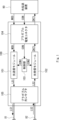
- FIG. 1 is a diagram schematically showing a configuration of a pluggable optical module according to Embodiment 1;
- FIG. 1 is a diagram schematically showing a configuration example of an optical transmission module according to a first embodiment;
- FIG. 1 is a diagram schematically showing the configuration of a light source unit according to Embodiment 1;
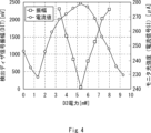
- FIG. 10 is a diagram showing changes in the intensity and wavelength of monitor light when the power supplied to the heater is changed by a driving signal superimposed with a dither signal;
- FIG. 1 schematically shows the configuration of a pluggable optical module 100 according to the first embodiment.
- the pluggable optical module 100 is controlled based on the control signal CON input from the optical transmission device 90, which is the communication host.
- the pluggable optical module 100 can receive the modulated signal MOD, which is a data signal, from the optical transmission device 90 together with the control signal CON, and output the optical signal LS1 modulated based on the modulated signal MOD to the optical fiber 81 .
- the pluggable optical module 100 can also receive the optical signal LS2 input from the optical fiber 82 and output the data signal DAT obtained by demodulating the optical signal LS2 to the optical transmission device 90 .
- the optical transmission device 90 performs communication data processing such as frame processing of a communication data signal from the pluggable optical module 100 or a communication data signal input to the pluggable optical module 100, for example.
- the pluggable optical module 100 has an optical transmission module 101 , an optical reception module 102 , a control section 103 , a pluggable electrical connector 104 and a pluggable optical receptor 105 .
- the pluggable electrical connector 104 is configured to be removable from the optical transmission device 90 .
- the pluggable electrical connector 104 receives the control signal CON, which is an electrical signal output from the optical transmission device 90 , and transfers it to the control unit 103 .
- the pluggable electrical connector 104 also receives the modulated signal MOD, which is an electrical signal output from the optical transmission device 90 , and transfers it to the optical transmission module 101 .
- the pluggable electrical connector 104 may transfer electrical signals output from the control section 103 to the optical transmission device 90 .
- the pluggable optical receptor 105 is configured such that a connector portion of an optical fiber 81 with a connector for transmission and a connector of an optical fiber 82 with a connector for reception can be inserted and removed.
- As connectors for the optical fibers 82 and 82 with connectors for example, LC type connectors or MU type connectors can be used.
- the pluggable optical receptor 105 transmits the optical signal LS1 output from the optical transmission module 101 to the optical fiber 81 and transmits the optical signal LS2 input from the optical fiber 82 to the optical reception module 102 .
- control unit 103 Based on the control signal CON input from the optical transmission device 90 via the pluggable electrical connector 104, the control unit 103 controls the operation of the optical transmission module 101 with the control signal CON1, and controls the operation of the optical reception module 102 with the control signal CON2. control behavior.
- the optical receiving module 102 demodulates the optical signal LS2 received via the pluggable optical receptor 105 into a data signal DAT, which is an electrical signal, and outputs the data signal DAT to the optical transmission device 90 via the pluggable electrical connector 104 .
- the optical receiver module 102 is configured to be able to demodulate the optical signal LS2 modulated by various modulation schemes.
- the optical transmission module 101 modulates the laser light output from the light source according to the modulation signal MOD, and outputs the optical signal LS1.
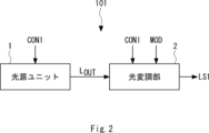
- FIG. 2 schematically shows a configuration example of the optical transmission module 101 according to the first embodiment.
- the optical transmission module 101 has a light source unit 1 and an optical modulation section 2 .
- the light source unit 1 is configured as a wavelength tunable optical module including a semiconductor optical device and a ring resonator, and outputs laser light L OUT of a predetermined wavelength to the optical modulator 2 .
- the optical modulation unit 2 is configured to have, for example, a Mach-Zehnder optical modulator and a drive circuit for driving it.
- the optical modulator 2 modulates the laser light L OUT according to the modulation signal MOD and outputs an optical signal LS1.
- the optical modulator 2 can modulate the optical signal LS1 by various modulation methods such as phase modulation, amplitude modulation, and polarization modulation, or by combining various modulation methods.
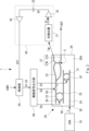
- FIG. 3 schematically shows the configuration of the light source unit 1 according to the first embodiment.
- the light source unit 1 has a semiconductor optical amplifier (hereinafter referred to as SOA) 10 , an external resonator 20 , an optical monitor section 30 , a drive signal output section 40 and a control section 50 .
- SOA semiconductor optical amplifier
- the SOA 10 is an active optical element that outputs light, and is configured as a semiconductor laser diode, for example.
- the SOA 10 is provided with an optical waveguide having a gain, for example, and emits laser light from the facet by laser oscillation by current injection or the like.
- the end surface 10A on the side of the external resonator 20 is coated with a low reflectance coating
- the opposite end surface 10B is coated with a high reflectance coating.
- the SOA 10 and the external resonator 20 are arranged with their waveguides aligned with each other, and the output light L, which is the laser beam of the SOA 10 , enters the external resonator 20 .
- the output light L has a certain spectral width, but its wavelength and phase can be adjusted by the external resonator 20, as will be described later.
- the external resonator 20 is configured as a resonator capable of resonating the output light L of the SOA 10 for laser oscillation and adjusting the wavelength and phase of the oscillated laser light L OUT .
- the external resonator 20 is a semiconductor device manufactured by silicon (Si) photonics technology, and is an external resonator having a wavelength tuning function.
- the external resonator 20 can be manufactured by a known Si process such as a CMOS (Complementary Metal Oxide Semiconductor) process.
- the configuration of the external resonator 20 will be described.
- the external resonator 20 has ring resonators 21 and 22, a loop mirror 23, silicon optical waveguides 24 to 26, an output optical waveguide 27, and heaters H1 to H3 formed on a substrate 20A.
- Ring resonators 21 and 22 are also referred to as first and second ring resonators, respectively.
- the substrate 20A is composed of, for example, a silicon substrate or an SOI (Silicon on Insulator) substrate.
- the silicon optical waveguides 24 to 26 are composed of thin wire waveguides or rib waveguides.
- the silicon optical waveguide 24 optically connects the incident end surface 28 and the ring resonator 21 .
- a silicon optical waveguide 25 optically connects between the ring resonator 21 and the ring resonator 22 .
- a silicon optical waveguide 26 optically connects between the ring resonator 22 and the loop mirror 23 .
- an anti-reflection coating (not shown) is formed on the end of the silicon optical waveguide 24 on the incident end face 28 side.
- the ring resonators 21 and 22 function as filters in which the wavelength of the transmitted light is variable, and the light resonates between the ring resonators 21 and 22 to cause laser oscillation.
- the ring resonators 21 and 22 are provided with heaters H1 and H2, respectively. By heating the silicon optical waveguide constituting the ring resonator 21 with the heater H1, the optical path length (in other words, the phase of propagating light) is changed, thereby controlling the wavelength of the light reflected by the ring resonator 21. be done.
- the optical path length (in other words, the phase of the propagating light) is changed, whereby the light reflected by the ring resonator 22 is changed.
- Wavelength is controlled.
- a heater H3 is provided in the silicon optical waveguide 26 between the loop mirror 23 and the ring resonator 22 .
- the optical path length of the silicon optical waveguide is changed. ) changes. Thereby, the phase of the laser light output from the resonator can be controlled.
- the heater H3 adjusts the phase of the laser reciprocating in the resonator formed between the end face 10B of the SOA 10 and the loop mirror so that the phase is in a positive feedback state, thereby continuing the laser oscillation. Moreover, the amplification of laser light can be maximized. In addition, the ring resonators 21 and 22 transmit only the laser light of the desired wavelength to the loop mirror 23, so that the laser light of the desired wavelength can be output as the laser light LOUT and the monitor light LM .
- the heaters H1-H3 are controlled by drive signals D1-D3 output from the drive signal output section 40, respectively.
- the curved portion of the loop mirror 23 is optically connected to the curved portion of the output optical waveguide 27 .
- the two silicon optical waveguides on both sides of the curved portion of the output optical waveguide 27 extend to the output end face 29, and most of the laser light incident on the loop mirror 23 is transferred to the output optical waveguide 27 by the coupling portion (coupler C).
- a portion of the laser beams other than the laser beams coupled to the laser beam output waveguide 27A are coupled to the monitor beam output waveguide 27B by the coupler C, and output as monitor beams LM . It is output to the monitor section 30 .
- the light monitor unit 30 is configured to monitor the intensity of the monitor light LM and output a detection dither signal DIT indicating the monitor result.
- the optical monitor section 30 has a photodetector 31 , a current-voltage converter 32 , a capacitor 33 and an amplifier 34 .
- the photodetector 31 detects the monitor light LM output from the external resonator 20 and outputs a signal indicating the intensity of the detected monitor light LM .
- the photodetector 31 is composed of, for example, a photodiode, and outputs a detection signal SI, which is a current signal indicating the intensity of the monitor light LM .
- the current-voltage converter 32 is composed of, for example, a TIA (Transimpedance Amplifier), converts the detection signal SI, which is a current signal, into a voltage signal SV and outputs the voltage signal SV.
- TIA Transimpedance Amplifier
- the voltage signal SV is input to the amplifier 34 via the capacitor 33 .
- a signal obtained by cutting the DC component from the voltage signal SV by the capacitor 33 is amplified by the amplifier 34 and then output to the control unit 50 as the detected dither signal DIT.
- the drive signal output unit 40 outputs drive signals D1 to D3 to the heaters H1 to H3, respectively, according to the control by the control unit 50.
- the configuration and operation of the light source unit 1 will be described below, focusing on the drive signal D3 applied to the heater H3.
- the drive signal output unit 40 can superimpose the applied dither signal on the drive signal D3 and output it.
- the dither signal superimposed on the driving signal is referred to as an applied dither signal for distinction, and is output from the optical monitor section 30 to detect the intensity amplitude generated in the laser light by the applied dither signal. This signal is referred to as the detection dither signal.
- the control unit 50 controls the drive signal output unit 40 with the signal S3 so that the drive signal D3 superimposed with the predetermined applied dither signal is output to the heater H3.
- the controller 50 can also control the drive signals D1 and D2 output to the heaters H1 and H2 by the signals S1 and 2.
- the control unit 50 controls heating by the heater H3 step by step in order to search for the optimum phase.
- the control unit 50 periodically changes the current of the drive signal D3 to be applied to the heater H3 within a range that does not affect the wavelength accuracy, thereby forming the applied dither signal.
- the applied dither signal is given as a rectangular wave with a predetermined cycle, and the amplitude of this rectangular wave changes stepwise.
- FIG. 4 shows changes in the intensity and wavelength of the monitor light when the power supplied to the heater H3 is changed by the drive signal D3 on which the applied dither signal is superimposed.
- the power applied to the heater H3 is changed from 0 [mW] to 9+4/3 [mW] in approximately 2/3 [mW] increments, and accordingly the detection dither signal DIT output by the optical monitor unit 30 is changed.
- Monitor amplitude changes.
- the current signal SI output by the photodetector 31 changes in conjunction with the cycle of the applied dither signal.
- the power of the drive signal D3 is approximately 1 to 5 [mW] and 6 to 9 [mW], and in the region where the current signal varies greatly with respect to the power change, that is, in the region where the differential value of the current signal is large, the drive signal Variations in the current signal that accompany changes in the applied dither signal superimposed on D3 also increase.
- the amplitude of the detection dither signal DIT output from the optical monitor section 30 also increases.
- the power of the drive signal D3 is in the range of about 5 to 6 [mW], the region where the current signal changes little with respect to the power change near the top of the curve showing the current, that is, the differential value of the current signal In a small region, the variation of the current signal caused by the variation of the applied dither signal superimposed on the drive signal D3 is also small. As a result, the amplitude of the detection dither signal DIT output by the optical monitor section 30 also decreases.
- the phase of the laser light is optimal, that is, the maximum oscillation intensity of the external resonator 20. becomes.
- the control unit 50 searches for the power value when the amplitude of the detected dither signal DIT becomes the minimum, and sets the searched power value as the power of the drive signal D3, thereby maximizing the oscillation intensity of the external resonator 20.
- a point can be determined.
- the amplitude of the detected dither signal DIT is minimum when the power of the drive signal D3 is approximately 5.33 mW, so in this case the power of the drive signal D3 is set to approximately 5.33 mW.
- the Rukoto This makes it possible to keep the phase of the laser light L OUT output from the light source unit 1 in an optimum state thereafter.
- the execution of setting the drive signal D3 is not limited to this example, and may be performed when calibrating the phase of the laser light L OUT after starting the operation of the pluggable optical module, or in other cases. You can do it at any time.
- the drive signal output unit 40 may be configured as an analog-digital converter (hereinafter referred to as DAC).
- DAC analog-digital converter
- the control unit 50 outputs the analog signal on which the applied dither signal component is superimposed to the drive signal output unit 40 as the signal S3.
- the drive signal output unit 40 converts the signal S3 into a digital signal and outputs it as a drive signal D3, and the heater H3 is directly driven by the drive signal D3 which is a digital signal.
- Patent Documents 1 and 3 a heater is used to control the phase of light in the modulator, but the driving signal is given to the heater as an analog signal.
- a driver (the controller in Patent Document 1 and the setting unit in Patent Document 3) is provided for controlling the current supplied to the heater.
- a driver has a relatively large circuit scale, resulting in an increase in the size of the light source unit.
- the present invention is not limited to the above-described embodiments, and can be modified as appropriate without departing from the scope of the invention.
- the configuration of the above-described pluggable optical module (optical transceiver) is simplified for the purpose of describing the optical transceiver according to the above-described embodiments, and various other components may be included. Needless to say.
Abstract
Un résonateur externe (20) émet un faisceau laser (LOUT) soumis à une oscillation laser par un résonateur optique constitué du résonateur externe (20) et d'un SOA (10). Un dispositif de chauffage (H3) commande la phase du faisceau laser (LOUT). Une unité de sortie de signal d'attaque (40) délivre en sortie un signal d'attaque (D3) au dispositif de chauffage (H3). Une unité de commande (50) commande le signal d'attaque (D3) fourni au dispositif de chauffage (H3) par l'unité de sortie de signal d'attaque (40). Une unité de surveillance optique (30) surveille l'intensité du faisceau laser (LOUT). L'unité de commande (50) superpose un signal de vibration appliqué à onde carrée sur le signal d'attaque (D3). L'unité de surveillance optique (30) détecte l'amplitude des fluctuations dans le faisceau laser (LOUT) dues au signal de vibration appliqué, et délivre en sortie le résultat de détection. L'unité de commande (50) modifie la puissance du signal d'attaque (D3), surveille le résultat de détection, trouve la puissance à l'amplitude minimale de la fluctuation dans le faisceau laser (LOUT), et établit la puissance du signal d'attaque (D3) à la puissance trouvée.
Priority Applications (1)
| Application Number | Priority Date | Filing Date | Title |
|---|---|---|---|
| PCT/JP2021/035996 WO2023053303A1 (fr) | 2021-09-29 | 2021-09-29 | Unité de source de lumière, module de transmission optique et module optique enfichable |
Applications Claiming Priority (1)
| Application Number | Priority Date | Filing Date | Title |
|---|---|---|---|
| PCT/JP2021/035996 WO2023053303A1 (fr) | 2021-09-29 | 2021-09-29 | Unité de source de lumière, module de transmission optique et module optique enfichable |
Publications (1)
| Publication Number | Publication Date |
|---|---|
| WO2023053303A1 true WO2023053303A1 (fr) | 2023-04-06 |
Family
ID=85780489
Family Applications (1)
| Application Number | Title | Priority Date | Filing Date |
|---|---|---|---|
| PCT/JP2021/035996 WO2023053303A1 (fr) | 2021-09-29 | 2021-09-29 | Unité de source de lumière, module de transmission optique et module optique enfichable |
Country Status (1)
| Country | Link |
|---|---|
| WO (1) | WO2023053303A1 (fr) |
Citations (7)
| Publication number | Priority date | Publication date | Assignee | Title |
|---|---|---|---|---|
| JP2008227418A (ja) * | 2007-03-15 | 2008-09-25 | Nec Corp | 制御装置、制御回路、制御方法及び制御プログラム |
| US20150323818A1 (en) * | 2013-01-25 | 2015-11-12 | The Trustees Of Columbia University In The City Of New York | Applications of wavelength-locking using dithering signals for microring resonators |
| WO2017006515A1 (fr) * | 2015-07-09 | 2017-01-12 | 日本電気株式会社 | Module optique enfichable, et système de communication optique |
| JP2017147622A (ja) * | 2016-02-17 | 2017-08-24 | 富士通オプティカルコンポーネンツ株式会社 | 光送信機、及び制御方法 |
| WO2018012054A1 (fr) * | 2016-07-15 | 2018-01-18 | 日本電気株式会社 | Émetteur et procédé d'ajustement de polarisation |
| WO2018146749A1 (fr) * | 2017-02-08 | 2018-08-16 | 古河電気工業株式会社 | Dispositif laser à longueur d'onde variable |
| US20190027898A1 (en) * | 2017-07-19 | 2019-01-24 | Axalume, Inc. | Single-Pass Ring-Modulated Laser |
-
2021
- 2021-09-29 WO PCT/JP2021/035996 patent/WO2023053303A1/fr active Application Filing
Patent Citations (7)
| Publication number | Priority date | Publication date | Assignee | Title |
|---|---|---|---|---|
| JP2008227418A (ja) * | 2007-03-15 | 2008-09-25 | Nec Corp | 制御装置、制御回路、制御方法及び制御プログラム |
| US20150323818A1 (en) * | 2013-01-25 | 2015-11-12 | The Trustees Of Columbia University In The City Of New York | Applications of wavelength-locking using dithering signals for microring resonators |
| WO2017006515A1 (fr) * | 2015-07-09 | 2017-01-12 | 日本電気株式会社 | Module optique enfichable, et système de communication optique |
| JP2017147622A (ja) * | 2016-02-17 | 2017-08-24 | 富士通オプティカルコンポーネンツ株式会社 | 光送信機、及び制御方法 |
| WO2018012054A1 (fr) * | 2016-07-15 | 2018-01-18 | 日本電気株式会社 | Émetteur et procédé d'ajustement de polarisation |
| WO2018146749A1 (fr) * | 2017-02-08 | 2018-08-16 | 古河電気工業株式会社 | Dispositif laser à longueur d'onde variable |
| US20190027898A1 (en) * | 2017-07-19 | 2019-01-24 | Axalume, Inc. | Single-Pass Ring-Modulated Laser |
Similar Documents
| Publication | Publication Date | Title |
|---|---|---|
| JP7342922B2 (ja) | プラガブル光トランシーバ及び光通信システム | |
| JP5835359B2 (ja) | 光送信器および光送信器の制御方法 | |
| US9583913B1 (en) | Tunable laser with integrated wavelength reference | |
| US7937000B2 (en) | Optical receiver and optical transceiver using the same | |
| US8145017B2 (en) | Optical module | |
| JP6733912B2 (ja) | プラガブル光モジュール及び光通信システム | |
| JP2009212494A (ja) | 光−マイクロ波発振器及びパルス発生装置 | |
| US8902937B2 (en) | Compact external cavity tunable laser apparatus | |
| US7639910B2 (en) | Optical module and method of packaging the same | |
| US11705692B2 (en) | Laser side mode suppression ratio control | |
| WO2023053303A1 (fr) | Unité de source de lumière, module de transmission optique et module optique enfichable | |
| JP2010245122A (ja) | 波長可変光源および狭線幅化方法 | |
| JPH0277630A (ja) | 半導体レーザの発振周波数安定化方法及び装置 | |
| JP2003307533A (ja) | 電界センシング・光伝送システム | |
| CN108886235A (zh) | 光源装置 | |
| JP3351212B2 (ja) | パルス光源 | |
| CN115037375B (zh) | 基于超高q封装微腔的超窄带宽微波光子可调谐滤波器 | |
| JP3104715B2 (ja) | 可変波長フィルタ装置 | |
| CN117791289A (zh) | 一种基于光纤f-p腔的pdh稳频全光纤化激光器系统 | |
| JP2000068581A (ja) | 光源モジュール | |
| CN116826512A (zh) | 一种基于对接耦合的混合集成多波长锁模激光器 | |
| JPH03241882A (ja) | レーザ発振波長安定化装置 | |
| JPH06125115A (ja) | 光送受信モジュール | |
| JPS60145737A (ja) | 光信号送信装置 |
Legal Events
| Date | Code | Title | Description |
|---|---|---|---|
| 121 | Ep: the epo has been informed by wipo that ep was designated in this application |
Ref document number: 21959345 Country of ref document: EP Kind code of ref document: A1 |
|
| WWE | Wipo information: entry into national phase |
Ref document number: 2023550871 Country of ref document: JP |