WO2023053248A1 - 電動車両の制御装置及び電動車両並びにコンピュータプログラムを記録した記録媒体 - Google Patents
電動車両の制御装置及び電動車両並びにコンピュータプログラムを記録した記録媒体 Download PDFInfo
- Publication number
- WO2023053248A1 WO2023053248A1 PCT/JP2021/035777 JP2021035777W WO2023053248A1 WO 2023053248 A1 WO2023053248 A1 WO 2023053248A1 JP 2021035777 W JP2021035777 W JP 2021035777W WO 2023053248 A1 WO2023053248 A1 WO 2023053248A1
- Authority
- WO
- WIPO (PCT)
- Prior art keywords
- torque
- current
- electric vehicle
- drive
- detected
- Prior art date
- Legal status (The legal status is an assumption and is not a legal conclusion. Google has not performed a legal analysis and makes no representation as to the accuracy of the status listed.)
- Ceased
Links
Images


Classifications
-
- B—PERFORMING OPERATIONS; TRANSPORTING
- B60—VEHICLES IN GENERAL
- B60L—PROPULSION OF ELECTRICALLY-PROPELLED VEHICLES; SUPPLYING ELECTRIC POWER FOR AUXILIARY EQUIPMENT OF ELECTRICALLY-PROPELLED VEHICLES; ELECTRODYNAMIC BRAKE SYSTEMS FOR VEHICLES IN GENERAL; MAGNETIC SUSPENSION OR LEVITATION FOR VEHICLES; MONITORING OPERATING VARIABLES OF ELECTRICALLY-PROPELLED VEHICLES; ELECTRIC SAFETY DEVICES FOR ELECTRICALLY-PROPELLED VEHICLES
- B60L15/00—Methods, circuits, or devices for controlling the traction-motor speed of electrically-propelled vehicles
- B60L15/20—Methods, circuits, or devices for controlling the traction-motor speed of electrically-propelled vehicles for control of the vehicle or its driving motor to achieve a desired performance, e.g. speed, torque, programmed variation of speed
-
- B—PERFORMING OPERATIONS; TRANSPORTING
- B60—VEHICLES IN GENERAL
- B60L—PROPULSION OF ELECTRICALLY-PROPELLED VEHICLES; SUPPLYING ELECTRIC POWER FOR AUXILIARY EQUIPMENT OF ELECTRICALLY-PROPELLED VEHICLES; ELECTRODYNAMIC BRAKE SYSTEMS FOR VEHICLES IN GENERAL; MAGNETIC SUSPENSION OR LEVITATION FOR VEHICLES; MONITORING OPERATING VARIABLES OF ELECTRICALLY-PROPELLED VEHICLES; ELECTRIC SAFETY DEVICES FOR ELECTRICALLY-PROPELLED VEHICLES
- B60L3/00—Electric devices on electrically-propelled vehicles for safety purposes; Monitoring operating variables, e.g. speed, deceleration or energy consumption
-
- B—PERFORMING OPERATIONS; TRANSPORTING
- B60—VEHICLES IN GENERAL
- B60L—PROPULSION OF ELECTRICALLY-PROPELLED VEHICLES; SUPPLYING ELECTRIC POWER FOR AUXILIARY EQUIPMENT OF ELECTRICALLY-PROPELLED VEHICLES; ELECTRODYNAMIC BRAKE SYSTEMS FOR VEHICLES IN GENERAL; MAGNETIC SUSPENSION OR LEVITATION FOR VEHICLES; MONITORING OPERATING VARIABLES OF ELECTRICALLY-PROPELLED VEHICLES; ELECTRIC SAFETY DEVICES FOR ELECTRICALLY-PROPELLED VEHICLES
- B60L3/00—Electric devices on electrically-propelled vehicles for safety purposes; Monitoring operating variables, e.g. speed, deceleration or energy consumption
- B60L3/0023—Detecting, eliminating, remedying or compensating for drive train abnormalities, e.g. failures within the drive train
- B60L3/0061—Detecting, eliminating, remedying or compensating for drive train abnormalities, e.g. failures within the drive train relating to electrical machines
-
- B—PERFORMING OPERATIONS; TRANSPORTING
- B60—VEHICLES IN GENERAL
- B60L—PROPULSION OF ELECTRICALLY-PROPELLED VEHICLES; SUPPLYING ELECTRIC POWER FOR AUXILIARY EQUIPMENT OF ELECTRICALLY-PROPELLED VEHICLES; ELECTRODYNAMIC BRAKE SYSTEMS FOR VEHICLES IN GENERAL; MAGNETIC SUSPENSION OR LEVITATION FOR VEHICLES; MONITORING OPERATING VARIABLES OF ELECTRICALLY-PROPELLED VEHICLES; ELECTRIC SAFETY DEVICES FOR ELECTRICALLY-PROPELLED VEHICLES
- B60L3/00—Electric devices on electrically-propelled vehicles for safety purposes; Monitoring operating variables, e.g. speed, deceleration or energy consumption
- B60L3/0023—Detecting, eliminating, remedying or compensating for drive train abnormalities, e.g. failures within the drive train
- B60L3/0084—Detecting, eliminating, remedying or compensating for drive train abnormalities, e.g. failures within the drive train relating to control modules
-
- B—PERFORMING OPERATIONS; TRANSPORTING
- B60—VEHICLES IN GENERAL
- B60L—PROPULSION OF ELECTRICALLY-PROPELLED VEHICLES; SUPPLYING ELECTRIC POWER FOR AUXILIARY EQUIPMENT OF ELECTRICALLY-PROPELLED VEHICLES; ELECTRODYNAMIC BRAKE SYSTEMS FOR VEHICLES IN GENERAL; MAGNETIC SUSPENSION OR LEVITATION FOR VEHICLES; MONITORING OPERATING VARIABLES OF ELECTRICALLY-PROPELLED VEHICLES; ELECTRIC SAFETY DEVICES FOR ELECTRICALLY-PROPELLED VEHICLES
- B60L50/00—Electric propulsion with power supplied within the vehicle
- B60L50/50—Electric propulsion with power supplied within the vehicle using propulsion power supplied by batteries or fuel cells
- B60L50/60—Electric propulsion with power supplied within the vehicle using propulsion power supplied by batteries or fuel cells using power supplied by batteries
-
- B—PERFORMING OPERATIONS; TRANSPORTING
- B60—VEHICLES IN GENERAL
- B60L—PROPULSION OF ELECTRICALLY-PROPELLED VEHICLES; SUPPLYING ELECTRIC POWER FOR AUXILIARY EQUIPMENT OF ELECTRICALLY-PROPELLED VEHICLES; ELECTRODYNAMIC BRAKE SYSTEMS FOR VEHICLES IN GENERAL; MAGNETIC SUSPENSION OR LEVITATION FOR VEHICLES; MONITORING OPERATING VARIABLES OF ELECTRICALLY-PROPELLED VEHICLES; ELECTRIC SAFETY DEVICES FOR ELECTRICALLY-PROPELLED VEHICLES
- B60L58/00—Methods or circuit arrangements for monitoring or controlling batteries or fuel cells, specially adapted for electric vehicles
- B60L58/10—Methods or circuit arrangements for monitoring or controlling batteries or fuel cells, specially adapted for electric vehicles for monitoring or controlling batteries
-
- B—PERFORMING OPERATIONS; TRANSPORTING
- B60—VEHICLES IN GENERAL
- B60L—PROPULSION OF ELECTRICALLY-PROPELLED VEHICLES; SUPPLYING ELECTRIC POWER FOR AUXILIARY EQUIPMENT OF ELECTRICALLY-PROPELLED VEHICLES; ELECTRODYNAMIC BRAKE SYSTEMS FOR VEHICLES IN GENERAL; MAGNETIC SUSPENSION OR LEVITATION FOR VEHICLES; MONITORING OPERATING VARIABLES OF ELECTRICALLY-PROPELLED VEHICLES; ELECTRIC SAFETY DEVICES FOR ELECTRICALLY-PROPELLED VEHICLES
- B60L9/00—Electric propulsion with power supply external to the vehicle
- B60L9/16—Electric propulsion with power supply external to the vehicle using AC induction motors
- B60L9/18—Electric propulsion with power supply external to the vehicle using AC induction motors fed from DC supply lines
-
- B—PERFORMING OPERATIONS; TRANSPORTING
- B60—VEHICLES IN GENERAL
- B60W—CONJOINT CONTROL OF VEHICLE SUB-UNITS OF DIFFERENT TYPE OR DIFFERENT FUNCTION; CONTROL SYSTEMS SPECIALLY ADAPTED FOR HYBRID VEHICLES; ROAD VEHICLE DRIVE CONTROL SYSTEMS FOR PURPOSES NOT RELATED TO THE CONTROL OF A PARTICULAR SUB-UNIT
- B60W10/00—Conjoint control of vehicle sub-units of different type or different function
- B60W10/04—Conjoint control of vehicle sub-units of different type or different function including control of propulsion units
- B60W10/08—Conjoint control of vehicle sub-units of different type or different function including control of propulsion units including control of electric propulsion units, e.g. motors or generators
-
- H—ELECTRICITY
- H02—GENERATION; CONVERSION OR DISTRIBUTION OF ELECTRIC POWER
- H02P—CONTROL OR REGULATION OF ELECTRIC MOTORS, ELECTRIC GENERATORS OR DYNAMO-ELECTRIC CONVERTERS; CONTROLLING TRANSFORMERS, REACTORS OR CHOKE COILS
- H02P5/00—Arrangements specially adapted for regulating or controlling the speed or torque of two or more electric motors
- H02P5/46—Arrangements specially adapted for regulating or controlling the speed or torque of two or more electric motors for speed regulation of two or more dynamo-electric motors in relation to one another
-
- Y—GENERAL TAGGING OF NEW TECHNOLOGICAL DEVELOPMENTS; GENERAL TAGGING OF CROSS-SECTIONAL TECHNOLOGIES SPANNING OVER SEVERAL SECTIONS OF THE IPC; TECHNICAL SUBJECTS COVERED BY FORMER USPC CROSS-REFERENCE ART COLLECTIONS [XRACs] AND DIGESTS
- Y02—TECHNOLOGIES OR APPLICATIONS FOR MITIGATION OR ADAPTATION AGAINST CLIMATE CHANGE
- Y02T—CLIMATE CHANGE MITIGATION TECHNOLOGIES RELATED TO TRANSPORTATION
- Y02T10/00—Road transport of goods or passengers
- Y02T10/60—Other road transportation technologies with climate change mitigation effect
- Y02T10/72—Electric energy management in electromobility
Definitions
- the present disclosure relates to an electric vehicle control device, an electric vehicle, and a recording medium recording a computer program.
- An electric vehicle includes a driving motor that outputs driving force and an inverter that drives the driving motor.
- Such electric vehicles require a system for detecting errors in drive motors, inverters, or peripheral devices thereof.
- Patent Document 1 discloses a control device for a hybrid vehicle having a motor/generator as a drive source, which includes a motor current feedback control circuit that controls the motor current supplied to the motor/generator based on the motor command torque,
- a control device is disclosed that is provided with a motor control system failure detection circuit that detects a failure of the motor control system based on the divergence torque between the motor command torque and the motor torque.
- the control device of Patent Literature 1 is configured to determine a motor torque divergence failure based on a failure determination value of torque divergence and a failure determination time during which the state exceeding the failure determination value continues.
- the failure detection function by the control device described in Patent Document 1 is the difference between the torque instruction value required for the drive motor and the output torque of the drive motor obtained from the motor current supplied to the drive motor from the inverter.
- the deviation torque which is the absolute value of , is used to detect the failure of the control system of the driving motor. That is, the failure detection function determines whether a current corresponding to the torque command value is appropriately supplied to the driving motor.
- the present disclosure has been made in view of the above problems, and an object of the present disclosure is to record an electric vehicle control device, an electric vehicle, and a computer program capable of determining an abnormality in a control parameter of a driving motor. It is to provide a recording medium.
- the present invention is applied to an electric vehicle control system including at least one driving motor that outputs driving torque and an inverter circuit that drives the driving motor.
- a control device for an electric vehicle comprising: one or more processors; and one or more memories communicatively connected to the processors, wherein the processors detect battery output detected by a first sensor Acquiring the detected value of the current and the detected value of the driving torque transmitted to the wheels detected by the second sensor, and obtaining the actual torque indicating the relationship between the current supplied to the inverter circuit and the driving torque transmitted to the wheels - Calculate the current characteristics, and determine the difference between the reference torque-current characteristics, which is the relationship between the torque command value of the drive motor and the target supply current to the drive motor, and the calculated actual torque-current characteristics.
- a control device for an electric vehicle is provided.
- a control system for an electric vehicle including at least one driving motor that outputs driving torque and an inverter circuit that drives the driving motor
- a control device for an electric vehicle applied to a vehicle which obtains a detection value of the output current of the battery detected by a first sensor and a detection value of the driving torque transmitted to the wheels detected by the second sensor an acquisition unit, a torque-current characteristic calculation unit that calculates a torque-current characteristic indicating the relationship between the output current of the battery and the drive torque transmitted to the wheels, and preset reference torque-current characteristics and torque-current characteristics. and a determination unit that determines a deviation from the electric vehicle control device.
- At least one drive motor that outputs a drive torque, an inverter circuit that drives the drive motor, and force acting on the wheels are detected.
- an electric vehicle that calculates a torque-current characteristic that indicates the relationship between the output current of the battery and the drive torque transmitted to the wheels, and determines the deviation between the preset reference torque-current characteristic and the torque-current characteristic. be done.
- control of an electric vehicle including at least one drive motor that outputs drive torque and an inverter circuit that drives the drive motor
- a recording medium recording a computer program applied to the system, which transmits to one or more processors the detection value of the battery output current detected by the first sensor and the wheel detected by the second sensor calculating the actual torque-current characteristic indicating the relationship between the current supplied to the inverter circuit and the driving torque transmitted to the wheels;
- a computer program for executing a process including determining a difference between a reference torque-current characteristic that sets a relationship between a torque instruction value and a target supply current to a drive motor and a calculated actual torque-current characteristic.
- FIG. 1 is a schematic diagram showing a configuration example of an electric vehicle including a control system including an electric vehicle control device according to an embodiment of the present disclosure
- FIG. 4 is a diagnostic table for determining an abnormality based on a torque instruction value and a battery output current value in a control system that does not have a force sensor
- 2 is a block diagram showing a configuration example of an electric vehicle control device according to the same embodiment
- FIG. 4 is a flowchart showing diagnostic processing executed by the control device for an electric vehicle according to the embodiment
- 6 is a flow chart showing a process of determining deviation in torque-current characteristics by the control device for an electric vehicle according to the embodiment
- FIG. 4 is an explanatory diagram showing a deviation in torque-current characteristics
- 4 is a diagnostic table for determining an abnormality by the control device for an electric vehicle according to the same embodiment
- 4 is a flowchart of an example of target supply current correction processing by the electric vehicle control device according to the embodiment
- FIG. 10 is an explanatory diagram showing an example in which an abnormality has occurred in one drive motor
- FIG. 1 is a schematic diagram showing a configuration example of an electric vehicle 1 equipped with a control system 10.
- FIG. An electric vehicle 1 shown in FIG. 1 is a four-wheeled vehicle having four wheels 3 .
- the electric vehicle 1 is not limited to a four-wheeled vehicle, and may be other vehicles including commercial vehicles such as two-wheeled vehicles, buses, and trucks.
- the four wheels 3 and the drive motors 7 and force sensors 11 provided for the respective wheels 3 are indicated by the suffixes LF (left front), RF (right front), LR ( left rear) and RR (right rear). Also, in the following description, the suffixes LF, RF, LR, and RR are omitted as appropriate, unless otherwise required.
- the control system 10 of the electric vehicle 1 includes a force sensor 11, a drive motor 7, an inverter unit 30, a battery unit 20 and a control device 50.
- the control system 10 supplies electric power accumulated in the battery 21 in the battery unit 20 to the driving motor 7, and transmits the driving torque output from the driving motor 7 to the wheels 3, thereby causing the electric vehicle 1 to run. .
- the battery unit 20 includes a battery 21 , a battery management device 23 and a current sensor 25 .
- the battery 21 is a rechargeable secondary battery.
- the battery 21 may be a lithium-ion battery with a rated output of 200V, but the type and rated output of the battery 21 are not particularly limited.
- the battery 21 is connected to the driving motor 7 via the inverter unit 30 and accumulates power supplied to the driving motor 7 .
- Current sensor 25 detects the output current of battery 21 .
- the current sensor 25 corresponds to the first sensor in the technique of the present disclosure.
- the battery unit 20 is provided with a voltage sensor that detects the output voltage of the battery 21 and a temperature sensor that detects the temperature of the battery 21 .
- the battery management device 23 acquires the open-circuit voltage, output voltage, output current, battery temperature, and the like of the battery 21 and transmits this information to the control device 50 .
- the drive motor 7 is connected to the wheels 3 via the axle 5 and outputs drive torque to be transmitted to the wheels 3 .
- the driving motor 7 may be, for example, a three-phase AC radial motor or an axial gap motor, but the number of phases and the type of motor are not particularly limited.
- the driving motor 7 has a function of receiving rotational torque from the wheel 3 side during deceleration of the electric vehicle 1 and performing regenerative power generation to generate braking force.
- one drive motor 7 is connected to one wheel 3.
- a front wheel drive motor that transmits drive torque to the left front wheel 3LF and the right front wheel 3RF
- the electric vehicle 1 may be provided with two drive motors, a rear wheel drive motor that transmits drive torque to the left rear wheel 3LR and the right rear wheel 3RR.
- the electric vehicle 1 may include one drive motor that transmits drive torque to the four wheels 3 .
- a differential mechanism may be provided between the left and right axles or between the front and rear drive shafts.
- Each wheel 3 is provided with a force sensor 11 that detects force acting on the wheel 3 .
- the force sensor 11 is configured to detect at least the driving torque (rotational torque) output from the driving motor 7 and transmitted to the wheels 3 or the driving force (driving force) in the longitudinal direction of the vehicle.
- the force sensor 11 corresponds to the second sensor in the technique of the present disclosure.
- the force sensor 11 detects the force acting on the axle 5 that supports the wheels 3 in the x direction (the axial direction of the axle and the direction perpendicular to the vehicle height direction), the y direction (the axial direction of the axle), and the z direction (the vehicle height direction).
- It may be a sensor that detects component forces and moments about axes in the x-, y-, and z-directions.
- the moment about the axis in the y direction corresponds to the drive torque output from the drive motor 7 .
- the component force in the x direction corresponds to the driving force of the wheels 3 .
- the type of force sensor 11 is not limited.
- the force sensor 11 may be a sensor that detects rotational torque acting on the wheels of the wheels 3 .
- a sensor signal output from the force sensor 11 is input to the control device 50 .
- the inverter unit 30 includes inverter circuits 31LF, 31RF, 31LR, and 31RR that supply power to the respective drive motors 7LF, 7RF, 7LR, and 7RR.
- Each inverter circuit 31 converts DC power swept from the battery 21 into three-phase AC power and supplies it to the driving motor 7 .
- the inverter circuit 31 also converts the three-phase AC power regenerated by the drive motor 7 into DC power and supplies the DC power to the battery 21 .
- the inverter unit 30 may include a step-up/step-down circuit. Driving of the inverter unit 30 is controlled by the control device 50 .
- the control device 50 functions as a device that diagnoses the control system 10 by one or more processors executing a computer program. Further, the control device 50 of the present embodiment has a function of acquiring a sensor signal of the force sensor 11 and performing signal processing, acquiring an operation amount of the accelerator pedal 8 and a steering angle of the steering wheel 6, and calculating a torque instruction value. function, a function of acquiring information such as the output voltage and output current of the battery 21 from the battery management device 23 to manage the power of the control system 10, and a function of controlling the driving of the inverter unit 30 based on the torque instruction value. .
- the control device 50 may be unitized as one device capable of realizing these multiple functions, or may be configured by a plurality of devices communicably connected to each other.
- the computer program is a computer program for causing a processor such as a CPU (Central Processing Unit) to execute operations to be executed by the control device 50, which will be described later.
- the computer program executed by the processor may be recorded in a recording medium functioning as a storage unit (memory) 53 provided in the control device 50, or may be stored in a recording medium built in the control device 50 or external to the control device 50. may be recorded on any recording medium that can be attached.
- Recording media for recording computer programs include magnetic media such as hard disks, floppy disks and magnetic tapes, optical media such as CD-ROMs (Compact Disk Read Only Memory), DVDs (Digital Versatile Disks) and Blu-ray (registered trademark). Recording media, magneto-optical media such as floptical disks, storage elements such as ROM (Read Only Memory) and RAM (Random Access Memory), and flash memory such as SSD (Solid State Drive) and USB (Universal Serial Bus) memory , and other programs.
- magnetic media such as hard disks, floppy disks and magnetic tapes
- optical media such as CD-ROMs (Compact Disk Read Only Memory), DVDs (Digital Versatile Disks) and Blu-ray (registered trademark).
- Recording media magneto-optical media such as floptical disks, storage elements such as ROM (Read Only Memory) and RAM (Random Access Memory), and flash memory such as SSD (Solid State Drive) and USB (Universal Serial Bus) memory ,
- Control device So far, configuration examples of the electric vehicle 1 and the control system 10 have been described.
- the control device 50 will be described in detail below.
- control device 50 In general, a vehicle is equipped with a large number of control devices, and each control device has a self-diagnostic function that detects an abnormality in a module controlled by each control device based on output current, output voltage, and the like. In the electric vehicle control system, the control device that controls the inverter unit and the drive motor is equipped with an abnormality diagnosis function for these modules. Duplication is required so that the abnormality can be detected by other control devices.
- a torque instruction value representing an acceleration request for an electric vehicle is an input to the control system, and a driving torque transmitted to the wheels is an output from the control system.
- the elements intervening between the input and output of the control system are "communication”, “inverter unit 30", “drive motor 7" and “battery 21".
- a control device that controls the inverter unit and the driving motor can read “no abnormality”, “abnormality of the inverter unit", “abnormality of the driving motor”, and " Monitor the number of revolutions of the drive motor. Also, the battery management device that controls the battery unit monitors “battery abnormality” and “battery output current”. Further, the control device that manages the calculation of the torque instruction value of the electric vehicle monitors the "torque instruction value”.
- the output of the driving motor in response to the input of the torque instruction value is Monitoring the number of revolutions is not appropriate. Therefore, it is not possible to determine an appropriate battery output current value for the torque instruction value. Therefore, in order to double the abnormality diagnosis of the inverter unit and the drive motor, it is only possible to determine whether the output current value of the battery is zero when the torque instruction value is not zero. In this case, even if the torque command value is not zero and the output current value of the battery is not zero, it is impossible to detect an abnormality in the inverter unit and the drive motor regardless of whether the drive motor is rotating. Needless to say, an abnormality in the control parameters of the inverter unit cannot be detected either.
- FIG. 2 shows a control system that does not have a force sensor and can detect only the torque instruction value and the battery output current value, and the control device that controls each module does not detect an abnormality by self-diagnosis. , shows a diagnostic table for determining anomalies. If the drive torque transmitted to the wheels, which is the output of the control system, cannot be detected, and if the output current of the battery is zero even though the torque indication value is not zero, each self-diagnosis Since no abnormality has been detected by the controller, it can be determined that there is an abnormality in the communication system between the control devices (No. 2).
- the control system 10 of the electric vehicle 1 includes a force sensor (second sensor) 11 capable of detecting the drive torque transmitted to the wheels 3, which is the output of the control system. .
- the control device 50 doubles abnormality diagnosis of the control system 10 by using the information of the drive torque detected by the force sensor 11 .
- the control device 50 can detect an abnormality in a control parameter for controlling driving of the drive motor 7 .
- FIG. 3 is a block diagram showing an example of the configuration of the control device 50.
- the control device 50 includes one or more processors and one or more memories such as RAM or ROM communicably connected to the processors.
- a part or all of the control device 50 may be composed of firmware or the like that can be updated, or may be a program module or the like that is executed by instructions from a processor.
- a force sensor 11 provided on each wheel 3 is connected to the control device 50 .
- An accelerator pedal sensor 8a for detecting the amount of operation of the accelerator pedal 8 and a steering angle sensor 6a for detecting the steering angle of the steering wheel 6 are connected to the control device 50 .
- the battery management device 23 and the inverter unit 30 are connected to the control device 50 .
- the control device 50 and each device are connected via a communication bus such as a dedicated line or a CAN (Controller Area Network).
- the control device 50 includes a processing unit 51 and a storage unit 53.
- the processing unit 51 includes an instruction torque calculation unit 61 , a battery information acquisition unit 63 , a force sensor output detection unit 65 , a torque output control unit 67 and a diagnosis unit 69 .
- the processing unit 51 is one or a plurality of processors such as a CPU. It is a function realized by executing a computer program by However, part of the command torque calculation unit 61, the battery information acquisition unit 63, the force sensor output detection unit 65, the torque output control unit 67, and the diagnosis unit 69 may be configured by analog circuits.
- the storage unit 53 includes one or more storage elements such as RAM or ROM, or a recording medium such as a hard disk or SSD.
- the storage unit 53 stores a computer program executed by the processing unit 51, various parameters used for executing the computer program, acquired data, calculation result data, and the like.
- the instruction torque calculation unit 61 calculates the torque instruction value Tq_req based on the operation amount of the accelerator pedal 8 indicated by the sensor signal output from the accelerator pedal sensor 8a.
- the command torque calculation unit 61 refers to a command torque map that indicates the relationship between the accelerator pedal operation amount and the torque command value, and obtains the torque command value Tq_req corresponding to the accelerator pedal 8 operation amount.
- the torque command value Tq_req obtained here is the sum of the torque command values Tq_req_LF, Tq_req_RF, Tq_req_LR and Tq_req_RR output from the four drive motors 7LF, 7RF, 7LR and 7RR.
- the instruction torque calculation unit 61 distributes the torque instruction value Tq_req to each of the drive motors 7LF, 7RF, 7LR, and 7RR, and the torque instruction values Tq_req_LF, Tq_req_LF, and Calculate Tq_req_RF, Tq_req_LR, and Tq_req_RR.
- the electric vehicle 1 of this embodiment is provided with one driving motor 7 for each wheel 3 . Therefore, the instruction torque calculation unit 61 calculates the torque instruction values Tq_req_LF, Tq_req_RF, Calculate Tq_req_LR and Tq_req_RR.
- the command torque calculation unit 61 calculates torque command values Tq_req_LF and Calculate Tq_req_RF, Tq_req_LR, and Tq_req_RR.
- the battery information acquisition unit 63 acquires information on the battery 21 transmitted from the battery management device 23 .
- the information on the battery 21 includes information on the open circuit voltage, output voltage, output current and temperature of the battery 21 .
- the battery information acquisition unit 63 acquires at least information on the detected value I_b of the output current of the battery 21 detected by the current sensor (first sensor) 25 .
- the force sensor output detection section 65 detects the force acting on each wheel 3 based on the sensor signal output from the force sensor (second sensor) 11 .
- the force sensor 11 is a sensor that detects the six component forces described above
- the force sensor output detection unit 65 detects the component force in each of the xyz directions output from the force sensor 11 and the moment acting around each axis in the xyz direction. Acquire a sensor signal (voltage value) indicating
- the force sensor output detection section 65 may be configured to acquire a signal output from an amplifier circuit that amplifies the sensor signal.
- the force sensor output detection unit 65 detects at least a moment acting around the axis in the y direction corresponding to the drive torque Tq_det output from the drive motor 7 . Further, in the present embodiment, the force sensor output detection unit 65 detects an x-direction force component corresponding to the driving force F_det of the wheels 3 .
- the torque output control unit 67 controls driving of the inverter circuits 31LF, 31RF, 31LR and 31RR, and controls driving (powering) and regeneration of the driving motors 7LF, 7RF, 7LR and 7RR.
- the torque output control unit 67 refers to the information of the reference torque-current characteristic map that indicates the relationship between the torque command value and the supply current, and the command torque calculation unit 61 obtains Based on the torque command values Tq_req_LF, Tq_req_RF, Tq_req_LR, Tq_req_RR obtained, the target supply currents I_tgt_LF, I_tgt_RF, I_tgt_LR, I_tgt_RR of the drive motors 7LF, 7RF, 7LR, 7RR are set, and the inverter circuits 31LF, 31RF, 31LR, It controls the driving of 31RR.
- a three-phase alternating current is supplied to each of the drive motors 7 , and drive torque is output to each of the wheels 3 by driving the drive motors 7 .
- the torque output control unit 67 causes the diagnosis unit 69 to determine the relationship between the preset reference torque-current characteristics map and the actual torque-current characteristics obtained by obtaining the relationship between the supply current and the drive torque.
- the target supply currents I_tgt_LF, I_tgt_RF, I_tgt_LR and I_tgt_RR of the drive motors 7LF, 7RF, 7LR and 7RR may be corrected using the deviation information.
- the drive of the inverter circuit 31 is controlled such that drive torque corresponding to the torque command values Tq_req_LF, Tq_req_RF, Tq_req_LR and Tq_req_RR are output from the respective drive motors 7LF, 7RF, 7LR and 7RR.
- the diagnosis unit 69 executes processing for diagnosing the control system 10 .
- the diagnostic unit 69 is configured to determine an abnormality of the control system 10 using information on the drive torque Tq_det output from the drive motor 7 detected by the force sensor (second sensor) 11. ing. Specifically, based on the detection result of the force sensor 11, the detection result of the accelerator pedal sensor 8a, and the detection result of the current sensor 25, the diagnosis unit 69 detects an abnormality in the drive system, the communication system, or the mechanical/mechanical system. determine. Abnormalities in the drive system are abnormalities occurring in the inverter unit 30 and the drive motor 7 .
- An abnormality in the communication system occurs in communication and transmission circuits between various sensors and the control device 50, and in communication and transmission circuits between control devices when the control device 50 is composed of a plurality of control devices. This is an anomaly.
- the mechanical/mechanical system abnormality is an abnormality in which the electric vehicle 1 cannot be driven even if the drive torque is transmitted to the wheels 3, such as when the wheels 3 are stuck.
- the diagnostic unit 69 detects the output current I_b of the battery 21 detected by the current sensor (first sensor) 25 and the output current from the drive motor 7 detected by the force sensor (second sensor) 11.
- the actual torque-current characteristic indicating the relationship with the driving torque Tq_det is calculated, and the deviation between the preset reference torque-current characteristic and the calculated actual torque-current characteristic is determined.
- the diagnosis unit 69 is configured to be able to determine whether there is an abnormality in the control parameters for controlling the driving of the drive motor 7 .
- Abnormalities in the control parameters may occur in each inverter circuit based on the torque command value Tq_req, such as a state in which the output efficiency of the drive torque with respect to the current supplied to the inverter circuit 31 is reduced, or a state in which the electrical resistance is increased due to heat generation.
- the reference torque-current characteristics used when setting the supply current to 31 and the characteristics of the drive torque of each drive motor 7 with respect to the current actually supplied to each inverter circuit do not match (shift). state.
- FIG. 4 is a flow chart showing diagnostic processing executed by the control device 50 .
- diagnosis processing described below may be always executed while the control system 10 is activated, and may be executed at appropriate timing such as when the control system 10 is activated, every predetermined travel distance, or every predetermined travel time. may be set to be
- the diagnosis unit 69 of the processing unit 51 acquires the torque instruction value Tq_req calculated by the instruction torque calculation unit 61 (step S11). Next, the diagnosis unit 69 determines whether or not the acquired torque command value Tq_req is a positive value (step S13). If the torque command value Tq_req is zero, that is, if the torque command value Tq_req is not a positive value (S13/No), the diagnostic unit 69 terminates the processing of this routine.
- Detected values Tq_det_LF, Tq_det_RF, Tq_det_LR, and Tq_det_LR of the drive torque transmitted to the wheels 3LF, 3RF, 3LR, and 3RR are detected as moments about the y-direction axes output from the force sensors 11LF, 11RF, 11LR, and 11RR. be.
- the diagnosis unit 69 determines whether or not the obtained detection value I_b of the output current of the battery 21 is a positive value (step S17).
- the diagnostic unit 69 sets the abnormality flag of the communication and transmission circuit. is set (step S19), and the processing of this routine ends.
- the diagnosis unit 69 determines that there is an abnormality in the communication system, and The processing of this routine ends because it is in a state where diagnostic processing cannot be performed.
- the diagnosis unit 69 determines that the sum Tq_det_tl of the acquired drive torque detection values Tq_det_LF, Tq_det_RF, Tq_det_LR, and Tq_det_LR is a positive value. (step S21).
- the diagnosis unit 69 sets an abnormality flag for the driving system including the inverter unit 30 and the driving motor 7 (step S23), and ends the processing of this routine.
- the torque command value Tq_req is input to the control system 10 as a whole, and the drive torque is not output even though there is an output current from the battery 21. Since it is determined that an abnormality has occurred somewhere in the drive motor 7 and the subsequent abnormality diagnosis processing cannot be performed, the processing of this routine ends.
- the diagnostic unit 69 detects the torque ⁇ A deviation of current characteristics is determined (step S25).
- FIG. 5 is a flow chart showing the process of determining the deviation of the torque-current characteristics.
- the diagnosis unit 69 determines the values of the inverter circuits 31LF, 31RF, 31LR, and 31RR.
- Supply currents I_inv_LF, I_inv_RF, I_inv_LR, and I_inv_RR are calculated (step S51).
- the diagnosis unit 69 refers to the torque command values Tq_req_LF, Tq_req_RF, Tq_req_LR, and Tq_req_RR of the four drive motors 7LF, 7RF, 7LR, and 7RR calculated by the command torque calculator 61, and distributes the torque command values. Find the ratio.
- the diagnosis unit 69 also multiplies the detection value I_b of the output current of the battery 21 by the distribution ratio to calculate supply currents I_inv_LF, I_inv_RF, I_inv_LR, and I_inv_RR of the inverter circuits 31LF, 31RF, 31LR, and 31RR.
- the diagnosis unit 69 obtains the actual torque-current characteristics for each driving motor 7 based on the calculated supply current I_inv and the driving torque Tq_det obtained in step S15 (step S53). Specifically, the diagnosis unit 69 refers to at least one data of the supply current I_inv and the driving torque Tq_det recorded in the storage unit 53, and determines the actual torque-current characteristic indicating the relationship between the supply current I_inv and the driving torque Tq_det. Calculate When there are many data on the supply current I_inv and the drive torque Tq_det, the diagnosis unit 69 may obtain an approximate line representing the characteristics of the drive torque Tq_det with respect to the supply current I_inv. However, in the present embodiment, at least one point of data is also referred to as the actual torque-current characteristic.
- the diagnostic unit 69 refers to the reference torque-current characteristic map recorded in the storage unit 53, and obtains the deviation between the reference torque-current characteristic and the calculated actual torque-current characteristic (step S55).
- the reference torque-current characteristic map is a map for setting the target supply current I_tgt from the torque instruction value Tq_req of each driving motor 7, and is obtained and stored in advance according to the specifications of the driving motor 7.
- FIG. 6 when the approximation line C_act of the actual torque-current characteristic is obtained in step S53, the diagnosis unit 69 detects the deviation from the characteristic line C0 set in the reference torque-current characteristic map. ask for D.
- the characteristic deviation D is the drive torque Tq_det and the torque instruction value Tq_req for the same supply current I_inv on the reference torque-current characteristic map. may be the difference (Tq_det-Tq_req).
- the deviation D of the characteristic is the torque instruction for the same supply current I_inv on the respective drive torque Tq_det and the reference torque-current characteristic map. It may be the average value of the difference (Tq_det ⁇ Tq_req) from the value Tq_req.
- the characteristic deviation D is the difference (Tq_det- Tq_req) may be the average value.
- the characteristic deviation D is not limited to the above example, and may be obtained according to any criteria.
- the diagnostic unit 69 determines whether or not the calculated actual torque-current characteristics are appropriate for each of the drive motors 7LF, 7RF, 7LR, and 7RR (step S27). For example, the diagnosis unit 69 may determine that the actual torque-current characteristic is appropriate when the characteristic deviation D obtained in step S55 is less than a predetermined threshold.
- the method of determining whether or not the actual torque-current characteristics are appropriate is not particularly limited. For example, when there are a plurality of stored data of supply current I_inv and drive torque Tq_det, actual torque - It may be determined that the current characteristics are not suitable.
- the diagnosis unit 69 displays the abnormality flags of the control parameters of the drive motor 7 and the inverter circuit 31 that have determined that the actual torque-current characteristics are not appropriate. is set (step S29), and the processing of this routine ends.
- the diagnosis unit 69 determines whether the electric vehicle 1 is running (step S31). In the present embodiment, the diagnostic unit 69 detects when the driving force, which is the force component in the x direction output from the force sensor 11, has a value representing the forward movement of the vehicle 1 based on a preset coordinate system. It is determined that the electric vehicle 1 is running.
- the diagnosis unit 69 may determine whether or not the electric vehicle 1 is running based on information on the number of revolutions of the wheels 3 or the vehicle speed. may be determined based on the detection data of a sensor that monitors . In this case, the behavior of the vehicle 1 can be judged more comprehensively, and a judgment criterion for the vehicle 1 as a whole can be provided instead of the judgment criterion for only one wheel.
- the diagnostic unit 69 sets a mechanical/mechanical system abnormality flag (step S33), and ends this routine.
- the diagnosis unit 69 refers to the diagnosis table and various flag states recorded in the storage unit 53 (step S35).
- the diagnostic table is data for judging abnormality by comparing the presence or absence of a torque instruction, the detection value of the current sensor 25, and the presence or absence of the detection value of the force sensor 11.
- the diagnosis unit 69 Based on the torque command value Tq_req acquired so far, the driving torque Tq_det and the driving force F_det detected by the force sensor 11, and the output current detection value I_b detected by the current sensor 25, the diagnosis unit 69 creates a diagnosis table is used to determine the presence or absence of an abnormality.
- FIG. 7 shows an example of a diagnosis table.
- a control system that does not have a force sensor, if both the torque command value and the battery output current are not zero or both are zero, even if there is an abnormality somewhere in the system as a whole, the wheels Since it was unclear whether the transmitted drive torque was appropriate, no abnormality could be detected (Nos. 1 and 3 in FIG. 2).
- the detected value of the force sensor 11 can be used. Abnormality can be detected even in the case of
- the diagnosis unit 69 detects the driving torque Tq_det detected by the force sensor 11 and the driving force It is determined as follows according to F_det. If the driving torque Tq_det and the driving force F_det detected by the force sensor 11 represent forward movement of the vehicle 1 based on a preset coordinate system (No. 1-a), the diagnostic unit 69 determines that the driving force is normal. When the drive torque Tq_det detected by the force sensor 11 is a positive value while the drive force F_det is zero (No.
- the diagnostic unit 69 determines that there is an abnormality in the mechanical/mechanical system.
- the drive torque Tq_det detected by the force sensor 11 is zero (No. 1-c, d)
- the diagnostic unit 69 determines that there is an abnormality in the drive system.
- the diagnostic unit 69 detects an abnormality in the communication system as in the example of FIG. I judge.
- the diagnosis unit 69 detects Determine as follows. If both the driving torque Tq_det and the driving force F_det detected by the force sensor 11 are positive values, or if either one of them is a positive value (No. 3-a, b), there is no torque instruction to the control system 10. Since the driving torque Tq_det or the driving force F_det is positive even though power is not supplied to the inverter unit 30, the diagnostic unit 69 determines that there is an abnormality in the communication system. However, in this case, the battery unit 20, the inverter unit 30, or the drive motor 7 may be abnormal. When the driving torque Tq_det and the driving force F_det detected by the force sensor 11 are both zero (No. 3-c), there is no input to the control system 10 and no output. are judged to be normal.
- the number on the diagnosis table Case 1-b corresponds to a case in which a mechanical/mechanical system abnormality flag is set in step S33.
- the No. of the diagnosis table Case 2 corresponds to the case where the communication system abnormality flag is set in step S19.
- the No. of the diagnosis table Cases 1-c and 1-d correspond to cases in which the drive system abnormality flag is set in step S23.
- the control parameter abnormality flag set in step S29 is No. in the diagnosis table. This case corresponds to case 1-a, and indicates a control parameter abnormality that cannot be determined by comparing the torque command value Tq_req, the detection value of the force sensor 11, and the detection value of the current sensor 25.
- the diagnosis unit 69 sets the corresponding flag if the corresponding flag is not set (step S37), and ends the processing of this routine. If the flag has already been set in steps S19, S23, S29 and S33, the state of the flag is maintained.
- the diagnosis unit 69 executes the abnormality diagnosis processing of the control system 10 as described above.
- the diagnosis section 69 notifies the driver of the occurrence of the abnormality.
- the diagnosis unit 69 notifies the occurrence of an abnormality by one or a plurality of means such as warning sound, voice, image display, and warning lamp.
- the location of the abnormality may also be notified.
- a record of the abnormal location may be kept so that the dealer or repair shop can find the abnormal location.
- the diagnosis unit 69 may limit the torque command value Tq_req or the output driving torque so that the electric vehicle 1 does not fall into a dangerous state.
- the torque output control unit 67 determines the difference between the reference torque-current characteristics and the actual torque-current characteristics based on the information.
- the target supply currents I_tgt_LF, I_tgt_RF, I_tgt_LR and I_tgt_RR of the driving motors 7LF, 7RF, 7LR and 7RR may be corrected.
- FIG. 8 is an explanatory diagram showing the target supply current correction process.
- the torque output control unit 67 determines whether or not the abnormality flag of the control parameter is set as a result of the abnormality diagnosis processing executed by the diagnosis unit 69 (step S61). If the control parameter abnormality flag is not set (S61/No), the torque output control unit 67 ends the processing of this routine without correcting the target supply currents I_tgt_LF, I_tgt_RF, I_tgt_LR, and I_tgt_RR.
- the torque output control unit 67 calculates the torque output from each of the driving motors 7LF, 7RF, 7LR, and 7RR calculated by the command torque calculation unit 61. Instruction values Tq_req_LF, Tq_req_RF, Tq_req_LR, and Tq_req_RR are acquired (step S63). Next, the torque output control unit 67 refers to the information on the difference D between the reference torque-current characteristics calculated in step S55 and the actual torque-current characteristics for each of the driving motors 7LF, 7RF, 7LR, and 7RR (step S65).
- the torque output control unit 67 obtains the target supply current I_tgt based on the approximation line Cact.
- the torque output control unit 67 may obtain a correction amount by multiplying the target supply current I_tgt by the ratio of the deviation D to the torque command value T_req when the characteristic deviation D is calculated, and add the result to the target supply current I_tgt.
- the method of correcting the target supply current I_tgt is not particularly limited.
- the control system 10 since the control system 10 according to the present embodiment includes the force sensor 11, by comparing the torque command value Tq_req, the detection value of the force sensor 11, and the detection value of the current sensor 25, the Abnormalities in the system, abnormalities in the communication system, and abnormalities in the drive system can be discriminated. As a result, when there is an abnormality in the control system 10, the location of the abnormality can be determined with high accuracy. Therefore, in the control system 10 having a plurality of drive motors 7, it is possible to determine which drive motor 7 has an abnormality. Consequently, it is possible to determine whether an abnormality has occurred in any of the drive motors 7 or whether the control system 10 as a whole has an abnormality.
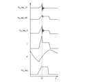
- FIG. 9 shows a torque command value Tq_req input to the control system, the vehicle speed V of the electric vehicle 1, the detected value I_b of the output current of the battery 21, and the Detected value Tq_det_LF of drive torque transmitted to the left front wheel, detected value Tq_det_RF of drive torque transmitted to the right front wheel, and sum Tq_det_tl of the left and right drive torques are shown.
- the horizontal axis indicates time t.
- control system 10 since the control system 10 according to the present embodiment includes the force sensor 11, an abnormality in the control parameters that cannot be detected by simply comparing the torque command value Tq_req, the detection value of the force sensor 11, and the detection value of the current sensor 25 can be determined. Therefore, it is possible to detect not only an abnormality occurring in each component of the control system 10 but also an abnormality in the control parameters for controlling the drive motor 7 .
- control device 50 can correct the target supply current I_tgt to the drive motor 7 according to the deviation between the reference torque-current characteristics and the actual torque-current characteristics. As a result, even when there is an abnormality in the control parameter, it is possible to output the drive torque according to the torque command value Tq_req, thereby reducing the discomfort felt by the driver.
Landscapes
- Engineering & Computer Science (AREA)
- Transportation (AREA)
- Mechanical Engineering (AREA)
- Power Engineering (AREA)
- Life Sciences & Earth Sciences (AREA)
- Sustainable Development (AREA)
- Sustainable Energy (AREA)
- Chemical & Material Sciences (AREA)
- Combustion & Propulsion (AREA)
- Electric Propulsion And Braking For Vehicles (AREA)
Priority Applications (5)
| Application Number | Priority Date | Filing Date | Title |
|---|---|---|---|
| PCT/JP2021/035777 WO2023053248A1 (ja) | 2021-09-29 | 2021-09-29 | 電動車両の制御装置及び電動車両並びにコンピュータプログラムを記録した記録媒体 |
| CN202180031689.2A CN116194321A (zh) | 2021-09-29 | 2021-09-29 | 电动车辆的控制装置、电动车辆以及记录有计算机程序的记录介质 |
| US17/925,797 US12508916B2 (en) | 2021-09-29 | 2021-09-29 | Control apparatus for electric vehicle, electric vehicle, and recording medium in which computer program is recorded |
| JP2023550827A JP7502573B2 (ja) | 2021-09-29 | 2021-09-29 | 電動車両の制御装置及び電動車両並びにコンピュータプログラムを記録した記録媒体 |
| DE112021008288.4T DE112021008288T5 (de) | 2021-09-29 | 2021-09-29 | Steuervorrichtung für ein elektrofahrzeug, elektrofahrzeug und aufzeichnungsmedium, in dem ein computerprogramm aufgezeichnet ist |
Applications Claiming Priority (1)
| Application Number | Priority Date | Filing Date | Title |
|---|---|---|---|
| PCT/JP2021/035777 WO2023053248A1 (ja) | 2021-09-29 | 2021-09-29 | 電動車両の制御装置及び電動車両並びにコンピュータプログラムを記録した記録媒体 |
Publications (1)
| Publication Number | Publication Date |
|---|---|
| WO2023053248A1 true WO2023053248A1 (ja) | 2023-04-06 |
Family
ID=85781544
Family Applications (1)
| Application Number | Title | Priority Date | Filing Date |
|---|---|---|---|
| PCT/JP2021/035777 Ceased WO2023053248A1 (ja) | 2021-09-29 | 2021-09-29 | 電動車両の制御装置及び電動車両並びにコンピュータプログラムを記録した記録媒体 |
Country Status (5)
| Country | Link |
|---|---|
| US (1) | US12508916B2 (https=) |
| JP (1) | JP7502573B2 (https=) |
| CN (1) | CN116194321A (https=) |
| DE (1) | DE112021008288T5 (https=) |
| WO (1) | WO2023053248A1 (https=) |
Families Citing this family (1)
| Publication number | Priority date | Publication date | Assignee | Title |
|---|---|---|---|---|
| KR20240042910A (ko) * | 2022-09-26 | 2024-04-02 | 현대자동차주식회사 | Hev 차량의 obd 제어기 시스템의 고장 진단 방법 |
Citations (3)
| Publication number | Priority date | Publication date | Assignee | Title |
|---|---|---|---|---|
| JP2017153358A (ja) * | 2017-04-14 | 2017-08-31 | Ntn株式会社 | モータ制御装置用外部接続装置 |
| WO2019130563A1 (ja) * | 2017-12-28 | 2019-07-04 | 三菱電機株式会社 | 電気車制御装置 |
| JP2021114866A (ja) * | 2020-01-21 | 2021-08-05 | 株式会社デンソー | 車両の駆動制御システム |
Family Cites Families (7)
| Publication number | Priority date | Publication date | Assignee | Title |
|---|---|---|---|---|
| JP5705585B2 (ja) * | 2011-02-25 | 2015-04-22 | Ntn株式会社 | 電気自動車 |
| US9448135B2 (en) * | 2014-07-16 | 2016-09-20 | Ford Global Technologies, Llc | Torque error detection and torque estimation system |
| JP2016043892A (ja) | 2014-08-26 | 2016-04-04 | 日産自動車株式会社 | 電動車両の制御装置 |
| US20200148064A1 (en) * | 2018-11-13 | 2020-05-14 | Ford Global Technologies, Llc | Power supply device |
| JP7201492B2 (ja) * | 2019-03-19 | 2023-01-10 | 株式会社Subaru | 車両の電力システム、車両の電力制御装置、車両の電力制御方法、およびプログラム |
| US11833713B2 (en) * | 2020-03-06 | 2023-12-05 | Oshkosh Corporation | Axle pressure setting systems and methods |
| JP7226376B2 (ja) * | 2020-03-10 | 2023-02-21 | 株式会社デンソー | 異常診断システム |
-
2021
- 2021-09-29 CN CN202180031689.2A patent/CN116194321A/zh active Pending
- 2021-09-29 DE DE112021008288.4T patent/DE112021008288T5/de active Pending
- 2021-09-29 JP JP2023550827A patent/JP7502573B2/ja active Active
- 2021-09-29 US US17/925,797 patent/US12508916B2/en active Active
- 2021-09-29 WO PCT/JP2021/035777 patent/WO2023053248A1/ja not_active Ceased
Patent Citations (3)
| Publication number | Priority date | Publication date | Assignee | Title |
|---|---|---|---|---|
| JP2017153358A (ja) * | 2017-04-14 | 2017-08-31 | Ntn株式会社 | モータ制御装置用外部接続装置 |
| WO2019130563A1 (ja) * | 2017-12-28 | 2019-07-04 | 三菱電機株式会社 | 電気車制御装置 |
| JP2021114866A (ja) * | 2020-01-21 | 2021-08-05 | 株式会社デンソー | 車両の駆動制御システム |
Also Published As
| Publication number | Publication date |
|---|---|
| US12508916B2 (en) | 2025-12-30 |
| DE112021008288T5 (de) | 2024-07-25 |
| US20240217344A1 (en) | 2024-07-04 |
| CN116194321A (zh) | 2023-05-30 |
| JP7502573B2 (ja) | 2024-06-18 |
| JPWO2023053248A1 (https=) | 2023-04-06 |
Similar Documents
| Publication | Publication Date | Title |
|---|---|---|
| CN106080206B (zh) | 一种电动汽车控制系统及方法 | |
| CN103118894B (zh) | 电动车辆的无认可蓄电池更换时对策装置 | |
| CN106427601B (zh) | 基于四轮驱动的电动汽车的制动系统及方法及电动汽车 | |
| EP2444293B1 (en) | Vehicle creep control device | |
| JP4835528B2 (ja) | 異常監視装置および異常監視方法 | |
| US10388973B2 (en) | Fuel cell stack diagnostic system and diagnostic method thereof | |
| CN105083257A (zh) | 用于使用偏航率检测制动系统的故障的方法 | |
| WO2018133630A1 (zh) | 一种分布式驱动城市客车多电机故障控制方法 | |
| US6318819B1 (en) | Method for handling errors in an electronic brake system and corresponding device | |
| JP7502573B2 (ja) | 電動車両の制御装置及び電動車両並びにコンピュータプログラムを記録した記録媒体 | |
| CN120382880A (zh) | 多致动器车辆系统的扭矩监控 | |
| CN118625784A (zh) | 一种车辆故障诊断方法及装置 | |
| JP6050089B2 (ja) | 電気自動車の制御装置およびその電気自動車 | |
| JP2008203962A (ja) | アラーム診断装置および診断方法 | |
| JP5531730B2 (ja) | 車両の制御装置 | |
| JP5245679B2 (ja) | 4wd車用シャシーダイナモメータ | |
| CN118182424A (zh) | 一种具有容错能力的分布式电动汽车线控制动系统 | |
| KR20220000428A (ko) | 차량의 전기장치 출력 제어 방법 | |
| CN114714915A (zh) | 电动汽车的能量回收监控方法、装置、车辆及存储介质 | |
| CN116901730A (zh) | 一种电动汽车驱动系统和电动汽车 | |
| CN212556207U (zh) | 一种刹车检测装置及刹车检测系统 | |
| CN120287858A (zh) | 电机扭矩控制方法、装置、电机控制器及车辆 | |
| JP2012191751A (ja) | 電動機のフェールセーフ装置 | |
| JP2016127713A (ja) | 四輪独立駆動車における一輪失陥時車両制御装置 | |
| JPWO2023053248A5 (https=) |
Legal Events
| Date | Code | Title | Description |
|---|---|---|---|
| WWE | Wipo information: entry into national phase |
Ref document number: 17925797 Country of ref document: US |
|
| 121 | Ep: the epo has been informed by wipo that ep was designated in this application |
Ref document number: 21959296 Country of ref document: EP Kind code of ref document: A1 |
|
| WWE | Wipo information: entry into national phase |
Ref document number: 2023550827 Country of ref document: JP |
|
| WWE | Wipo information: entry into national phase |
Ref document number: 112021008288 Country of ref document: DE |
|
| 122 | Ep: pct application non-entry in european phase |
Ref document number: 21959296 Country of ref document: EP Kind code of ref document: A1 |
|
| WWG | Wipo information: grant in national office |
Ref document number: 17925797 Country of ref document: US |