WO2023053248A1 - Control device for electric vehicle, electric vehicle, and recording medium on which computer program is recorded - Google Patents
Control device for electric vehicle, electric vehicle, and recording medium on which computer program is recorded Download PDFInfo
- Publication number
- WO2023053248A1 WO2023053248A1 PCT/JP2021/035777 JP2021035777W WO2023053248A1 WO 2023053248 A1 WO2023053248 A1 WO 2023053248A1 JP 2021035777 W JP2021035777 W JP 2021035777W WO 2023053248 A1 WO2023053248 A1 WO 2023053248A1
- Authority
- WO
- WIPO (PCT)
- Prior art keywords
- torque
- current
- electric vehicle
- drive
- detected
- Prior art date
Links
- 238000004590 computer program Methods 0.000 title claims abstract description 16
- 230000005856 abnormality Effects 0.000 claims abstract description 85
- 238000003745 diagnosis Methods 0.000 claims description 53
- 238000001514 detection method Methods 0.000 claims description 39
- 238000012545 processing Methods 0.000 claims description 31
- 238000004364 calculation method Methods 0.000 claims description 15
- 230000006870 function Effects 0.000 claims description 15
- 230000015654 memory Effects 0.000 claims description 10
- 238000004891 communication Methods 0.000 description 13
- 238000000034 method Methods 0.000 description 8
- 238000010586 diagram Methods 0.000 description 7
- 230000002159 abnormal effect Effects 0.000 description 4
- 230000008569 process Effects 0.000 description 4
- 230000005540 biological transmission Effects 0.000 description 3
- 238000012937 correction Methods 0.000 description 3
- 238000012544 monitoring process Methods 0.000 description 3
- 101150071661 SLC25A20 gene Proteins 0.000 description 2
- 101150102633 cact gene Proteins 0.000 description 2
- 230000007246 mechanism Effects 0.000 description 2
- 238000012986 modification Methods 0.000 description 2
- 230000004048 modification Effects 0.000 description 2
- 238000004092 self-diagnosis Methods 0.000 description 2
- HBBGRARXTFLTSG-UHFFFAOYSA-N Lithium ion Chemical compound [Li+] HBBGRARXTFLTSG-UHFFFAOYSA-N 0.000 description 1
- 230000001133 acceleration Effects 0.000 description 1
- 230000006399 behavior Effects 0.000 description 1
- 239000000470 constituent Substances 0.000 description 1
- 230000020169 heat generation Effects 0.000 description 1
- 229910001416 lithium ion Inorganic materials 0.000 description 1
- 230000003287 optical effect Effects 0.000 description 1
- 230000002093 peripheral effect Effects 0.000 description 1
- 238000010248 power generation Methods 0.000 description 1
- 230000002250 progressing effect Effects 0.000 description 1
- 230000001172 regenerating effect Effects 0.000 description 1
- 230000008929 regeneration Effects 0.000 description 1
- 238000011069 regeneration method Methods 0.000 description 1
- 230000008439 repair process Effects 0.000 description 1
- 230000004044 response Effects 0.000 description 1
- 239000007787 solid Substances 0.000 description 1
Images


Classifications
-
- B—PERFORMING OPERATIONS; TRANSPORTING
- B60—VEHICLES IN GENERAL
- B60L—PROPULSION OF ELECTRICALLY-PROPELLED VEHICLES; SUPPLYING ELECTRIC POWER FOR AUXILIARY EQUIPMENT OF ELECTRICALLY-PROPELLED VEHICLES; ELECTRODYNAMIC BRAKE SYSTEMS FOR VEHICLES IN GENERAL; MAGNETIC SUSPENSION OR LEVITATION FOR VEHICLES; MONITORING OPERATING VARIABLES OF ELECTRICALLY-PROPELLED VEHICLES; ELECTRIC SAFETY DEVICES FOR ELECTRICALLY-PROPELLED VEHICLES
- B60L15/00—Methods, circuits, or devices for controlling the traction-motor speed of electrically-propelled vehicles
- B60L15/20—Methods, circuits, or devices for controlling the traction-motor speed of electrically-propelled vehicles for control of the vehicle or its driving motor to achieve a desired performance, e.g. speed, torque, programmed variation of speed
-
- B—PERFORMING OPERATIONS; TRANSPORTING
- B60—VEHICLES IN GENERAL
- B60L—PROPULSION OF ELECTRICALLY-PROPELLED VEHICLES; SUPPLYING ELECTRIC POWER FOR AUXILIARY EQUIPMENT OF ELECTRICALLY-PROPELLED VEHICLES; ELECTRODYNAMIC BRAKE SYSTEMS FOR VEHICLES IN GENERAL; MAGNETIC SUSPENSION OR LEVITATION FOR VEHICLES; MONITORING OPERATING VARIABLES OF ELECTRICALLY-PROPELLED VEHICLES; ELECTRIC SAFETY DEVICES FOR ELECTRICALLY-PROPELLED VEHICLES
- B60L3/00—Electric devices on electrically-propelled vehicles for safety purposes; Monitoring operating variables, e.g. speed, deceleration or energy consumption
-
- B—PERFORMING OPERATIONS; TRANSPORTING
- B60—VEHICLES IN GENERAL
- B60L—PROPULSION OF ELECTRICALLY-PROPELLED VEHICLES; SUPPLYING ELECTRIC POWER FOR AUXILIARY EQUIPMENT OF ELECTRICALLY-PROPELLED VEHICLES; ELECTRODYNAMIC BRAKE SYSTEMS FOR VEHICLES IN GENERAL; MAGNETIC SUSPENSION OR LEVITATION FOR VEHICLES; MONITORING OPERATING VARIABLES OF ELECTRICALLY-PROPELLED VEHICLES; ELECTRIC SAFETY DEVICES FOR ELECTRICALLY-PROPELLED VEHICLES
- B60L9/00—Electric propulsion with power supply external to the vehicle
- B60L9/16—Electric propulsion with power supply external to the vehicle using ac induction motors
- B60L9/18—Electric propulsion with power supply external to the vehicle using ac induction motors fed from dc supply lines
-
- Y—GENERAL TAGGING OF NEW TECHNOLOGICAL DEVELOPMENTS; GENERAL TAGGING OF CROSS-SECTIONAL TECHNOLOGIES SPANNING OVER SEVERAL SECTIONS OF THE IPC; TECHNICAL SUBJECTS COVERED BY FORMER USPC CROSS-REFERENCE ART COLLECTIONS [XRACs] AND DIGESTS
- Y02—TECHNOLOGIES OR APPLICATIONS FOR MITIGATION OR ADAPTATION AGAINST CLIMATE CHANGE
- Y02T—CLIMATE CHANGE MITIGATION TECHNOLOGIES RELATED TO TRANSPORTATION
- Y02T10/00—Road transport of goods or passengers
- Y02T10/60—Other road transportation technologies with climate change mitigation effect
- Y02T10/72—Electric energy management in electromobility
Definitions
- the present disclosure relates to an electric vehicle control device, an electric vehicle, and a recording medium recording a computer program.
- An electric vehicle includes a driving motor that outputs driving force and an inverter that drives the driving motor.
- Such electric vehicles require a system for detecting errors in drive motors, inverters, or peripheral devices thereof.
- Patent Document 1 discloses a control device for a hybrid vehicle having a motor/generator as a drive source, which includes a motor current feedback control circuit that controls the motor current supplied to the motor/generator based on the motor command torque,
- a control device is disclosed that is provided with a motor control system failure detection circuit that detects a failure of the motor control system based on the divergence torque between the motor command torque and the motor torque.
- the control device of Patent Literature 1 is configured to determine a motor torque divergence failure based on a failure determination value of torque divergence and a failure determination time during which the state exceeding the failure determination value continues.
- the failure detection function by the control device described in Patent Document 1 is the difference between the torque instruction value required for the drive motor and the output torque of the drive motor obtained from the motor current supplied to the drive motor from the inverter.
- the deviation torque which is the absolute value of , is used to detect the failure of the control system of the driving motor. That is, the failure detection function determines whether a current corresponding to the torque command value is appropriately supplied to the driving motor.
- the present disclosure has been made in view of the above problems, and an object of the present disclosure is to record an electric vehicle control device, an electric vehicle, and a computer program capable of determining an abnormality in a control parameter of a driving motor. It is to provide a recording medium.
- the present invention is applied to an electric vehicle control system including at least one driving motor that outputs driving torque and an inverter circuit that drives the driving motor.
- a control device for an electric vehicle comprising: one or more processors; and one or more memories communicatively connected to the processors, wherein the processors detect battery output detected by a first sensor Acquiring the detected value of the current and the detected value of the driving torque transmitted to the wheels detected by the second sensor, and obtaining the actual torque indicating the relationship between the current supplied to the inverter circuit and the driving torque transmitted to the wheels - Calculate the current characteristics, and determine the difference between the reference torque-current characteristics, which is the relationship between the torque command value of the drive motor and the target supply current to the drive motor, and the calculated actual torque-current characteristics.
- a control device for an electric vehicle is provided.
- a control system for an electric vehicle including at least one driving motor that outputs driving torque and an inverter circuit that drives the driving motor
- a control device for an electric vehicle applied to a vehicle which obtains a detection value of the output current of the battery detected by a first sensor and a detection value of the driving torque transmitted to the wheels detected by the second sensor an acquisition unit, a torque-current characteristic calculation unit that calculates a torque-current characteristic indicating the relationship between the output current of the battery and the drive torque transmitted to the wheels, and preset reference torque-current characteristics and torque-current characteristics. and a determination unit that determines a deviation from the electric vehicle control device.
- At least one drive motor that outputs a drive torque, an inverter circuit that drives the drive motor, and force acting on the wheels are detected.
- an electric vehicle that calculates a torque-current characteristic that indicates the relationship between the output current of the battery and the drive torque transmitted to the wheels, and determines the deviation between the preset reference torque-current characteristic and the torque-current characteristic. be done.
- control of an electric vehicle including at least one drive motor that outputs drive torque and an inverter circuit that drives the drive motor
- a recording medium recording a computer program applied to the system, which transmits to one or more processors the detection value of the battery output current detected by the first sensor and the wheel detected by the second sensor calculating the actual torque-current characteristic indicating the relationship between the current supplied to the inverter circuit and the driving torque transmitted to the wheels;
- a computer program for executing a process including determining a difference between a reference torque-current characteristic that sets a relationship between a torque instruction value and a target supply current to a drive motor and a calculated actual torque-current characteristic.
- FIG. 1 is a schematic diagram showing a configuration example of an electric vehicle including a control system including an electric vehicle control device according to an embodiment of the present disclosure
- FIG. 4 is a diagnostic table for determining an abnormality based on a torque instruction value and a battery output current value in a control system that does not have a force sensor
- 2 is a block diagram showing a configuration example of an electric vehicle control device according to the same embodiment
- FIG. 4 is a flowchart showing diagnostic processing executed by the control device for an electric vehicle according to the embodiment
- 6 is a flow chart showing a process of determining deviation in torque-current characteristics by the control device for an electric vehicle according to the embodiment
- FIG. 4 is an explanatory diagram showing a deviation in torque-current characteristics
- 4 is a diagnostic table for determining an abnormality by the control device for an electric vehicle according to the same embodiment
- 4 is a flowchart of an example of target supply current correction processing by the electric vehicle control device according to the embodiment
- FIG. 10 is an explanatory diagram showing an example in which an abnormality has occurred in one drive motor
- FIG. 1 is a schematic diagram showing a configuration example of an electric vehicle 1 equipped with a control system 10.
- FIG. An electric vehicle 1 shown in FIG. 1 is a four-wheeled vehicle having four wheels 3 .
- the electric vehicle 1 is not limited to a four-wheeled vehicle, and may be other vehicles including commercial vehicles such as two-wheeled vehicles, buses, and trucks.
- the four wheels 3 and the drive motors 7 and force sensors 11 provided for the respective wheels 3 are indicated by the suffixes LF (left front), RF (right front), LR ( left rear) and RR (right rear). Also, in the following description, the suffixes LF, RF, LR, and RR are omitted as appropriate, unless otherwise required.
- the control system 10 of the electric vehicle 1 includes a force sensor 11, a drive motor 7, an inverter unit 30, a battery unit 20 and a control device 50.
- the control system 10 supplies electric power accumulated in the battery 21 in the battery unit 20 to the driving motor 7, and transmits the driving torque output from the driving motor 7 to the wheels 3, thereby causing the electric vehicle 1 to run. .
- the battery unit 20 includes a battery 21 , a battery management device 23 and a current sensor 25 .
- the battery 21 is a rechargeable secondary battery.
- the battery 21 may be a lithium-ion battery with a rated output of 200V, but the type and rated output of the battery 21 are not particularly limited.
- the battery 21 is connected to the driving motor 7 via the inverter unit 30 and accumulates power supplied to the driving motor 7 .
- Current sensor 25 detects the output current of battery 21 .
- the current sensor 25 corresponds to the first sensor in the technique of the present disclosure.
- the battery unit 20 is provided with a voltage sensor that detects the output voltage of the battery 21 and a temperature sensor that detects the temperature of the battery 21 .
- the battery management device 23 acquires the open-circuit voltage, output voltage, output current, battery temperature, and the like of the battery 21 and transmits this information to the control device 50 .
- the drive motor 7 is connected to the wheels 3 via the axle 5 and outputs drive torque to be transmitted to the wheels 3 .
- the driving motor 7 may be, for example, a three-phase AC radial motor or an axial gap motor, but the number of phases and the type of motor are not particularly limited.
- the driving motor 7 has a function of receiving rotational torque from the wheel 3 side during deceleration of the electric vehicle 1 and performing regenerative power generation to generate braking force.
- one drive motor 7 is connected to one wheel 3.
- a front wheel drive motor that transmits drive torque to the left front wheel 3LF and the right front wheel 3RF
- the electric vehicle 1 may be provided with two drive motors, a rear wheel drive motor that transmits drive torque to the left rear wheel 3LR and the right rear wheel 3RR.
- the electric vehicle 1 may include one drive motor that transmits drive torque to the four wheels 3 .
- a differential mechanism may be provided between the left and right axles or between the front and rear drive shafts.
- Each wheel 3 is provided with a force sensor 11 that detects force acting on the wheel 3 .
- the force sensor 11 is configured to detect at least the driving torque (rotational torque) output from the driving motor 7 and transmitted to the wheels 3 or the driving force (driving force) in the longitudinal direction of the vehicle.
- the force sensor 11 corresponds to the second sensor in the technique of the present disclosure.
- the force sensor 11 detects the force acting on the axle 5 that supports the wheels 3 in the x direction (the axial direction of the axle and the direction perpendicular to the vehicle height direction), the y direction (the axial direction of the axle), and the z direction (the vehicle height direction).
- It may be a sensor that detects component forces and moments about axes in the x-, y-, and z-directions.
- the moment about the axis in the y direction corresponds to the drive torque output from the drive motor 7 .
- the component force in the x direction corresponds to the driving force of the wheels 3 .
- the type of force sensor 11 is not limited.
- the force sensor 11 may be a sensor that detects rotational torque acting on the wheels of the wheels 3 .
- a sensor signal output from the force sensor 11 is input to the control device 50 .
- the inverter unit 30 includes inverter circuits 31LF, 31RF, 31LR, and 31RR that supply power to the respective drive motors 7LF, 7RF, 7LR, and 7RR.
- Each inverter circuit 31 converts DC power swept from the battery 21 into three-phase AC power and supplies it to the driving motor 7 .
- the inverter circuit 31 also converts the three-phase AC power regenerated by the drive motor 7 into DC power and supplies the DC power to the battery 21 .
- the inverter unit 30 may include a step-up/step-down circuit. Driving of the inverter unit 30 is controlled by the control device 50 .
- the control device 50 functions as a device that diagnoses the control system 10 by one or more processors executing a computer program. Further, the control device 50 of the present embodiment has a function of acquiring a sensor signal of the force sensor 11 and performing signal processing, acquiring an operation amount of the accelerator pedal 8 and a steering angle of the steering wheel 6, and calculating a torque instruction value. function, a function of acquiring information such as the output voltage and output current of the battery 21 from the battery management device 23 to manage the power of the control system 10, and a function of controlling the driving of the inverter unit 30 based on the torque instruction value. .
- the control device 50 may be unitized as one device capable of realizing these multiple functions, or may be configured by a plurality of devices communicably connected to each other.
- the computer program is a computer program for causing a processor such as a CPU (Central Processing Unit) to execute operations to be executed by the control device 50, which will be described later.
- the computer program executed by the processor may be recorded in a recording medium functioning as a storage unit (memory) 53 provided in the control device 50, or may be stored in a recording medium built in the control device 50 or external to the control device 50. may be recorded on any recording medium that can be attached.
- Recording media for recording computer programs include magnetic media such as hard disks, floppy disks and magnetic tapes, optical media such as CD-ROMs (Compact Disk Read Only Memory), DVDs (Digital Versatile Disks) and Blu-ray (registered trademark). Recording media, magneto-optical media such as floptical disks, storage elements such as ROM (Read Only Memory) and RAM (Random Access Memory), and flash memory such as SSD (Solid State Drive) and USB (Universal Serial Bus) memory , and other programs.
- magnetic media such as hard disks, floppy disks and magnetic tapes
- optical media such as CD-ROMs (Compact Disk Read Only Memory), DVDs (Digital Versatile Disks) and Blu-ray (registered trademark).
- Recording media magneto-optical media such as floptical disks, storage elements such as ROM (Read Only Memory) and RAM (Random Access Memory), and flash memory such as SSD (Solid State Drive) and USB (Universal Serial Bus) memory ,
- Control device So far, configuration examples of the electric vehicle 1 and the control system 10 have been described.
- the control device 50 will be described in detail below.
- control device 50 In general, a vehicle is equipped with a large number of control devices, and each control device has a self-diagnostic function that detects an abnormality in a module controlled by each control device based on output current, output voltage, and the like. In the electric vehicle control system, the control device that controls the inverter unit and the drive motor is equipped with an abnormality diagnosis function for these modules. Duplication is required so that the abnormality can be detected by other control devices.
- a torque instruction value representing an acceleration request for an electric vehicle is an input to the control system, and a driving torque transmitted to the wheels is an output from the control system.
- the elements intervening between the input and output of the control system are "communication”, “inverter unit 30", “drive motor 7" and “battery 21".
- a control device that controls the inverter unit and the driving motor can read “no abnormality”, “abnormality of the inverter unit", “abnormality of the driving motor”, and " Monitor the number of revolutions of the drive motor. Also, the battery management device that controls the battery unit monitors “battery abnormality” and “battery output current”. Further, the control device that manages the calculation of the torque instruction value of the electric vehicle monitors the "torque instruction value”.
- the output of the driving motor in response to the input of the torque instruction value is Monitoring the number of revolutions is not appropriate. Therefore, it is not possible to determine an appropriate battery output current value for the torque instruction value. Therefore, in order to double the abnormality diagnosis of the inverter unit and the drive motor, it is only possible to determine whether the output current value of the battery is zero when the torque instruction value is not zero. In this case, even if the torque command value is not zero and the output current value of the battery is not zero, it is impossible to detect an abnormality in the inverter unit and the drive motor regardless of whether the drive motor is rotating. Needless to say, an abnormality in the control parameters of the inverter unit cannot be detected either.
- FIG. 2 shows a control system that does not have a force sensor and can detect only the torque instruction value and the battery output current value, and the control device that controls each module does not detect an abnormality by self-diagnosis. , shows a diagnostic table for determining anomalies. If the drive torque transmitted to the wheels, which is the output of the control system, cannot be detected, and if the output current of the battery is zero even though the torque indication value is not zero, each self-diagnosis Since no abnormality has been detected by the controller, it can be determined that there is an abnormality in the communication system between the control devices (No. 2).
- the control system 10 of the electric vehicle 1 includes a force sensor (second sensor) 11 capable of detecting the drive torque transmitted to the wheels 3, which is the output of the control system. .
- the control device 50 doubles abnormality diagnosis of the control system 10 by using the information of the drive torque detected by the force sensor 11 .
- the control device 50 can detect an abnormality in a control parameter for controlling driving of the drive motor 7 .
- FIG. 3 is a block diagram showing an example of the configuration of the control device 50.
- the control device 50 includes one or more processors and one or more memories such as RAM or ROM communicably connected to the processors.
- a part or all of the control device 50 may be composed of firmware or the like that can be updated, or may be a program module or the like that is executed by instructions from a processor.
- a force sensor 11 provided on each wheel 3 is connected to the control device 50 .
- An accelerator pedal sensor 8a for detecting the amount of operation of the accelerator pedal 8 and a steering angle sensor 6a for detecting the steering angle of the steering wheel 6 are connected to the control device 50 .
- the battery management device 23 and the inverter unit 30 are connected to the control device 50 .
- the control device 50 and each device are connected via a communication bus such as a dedicated line or a CAN (Controller Area Network).
- the control device 50 includes a processing unit 51 and a storage unit 53.
- the processing unit 51 includes an instruction torque calculation unit 61 , a battery information acquisition unit 63 , a force sensor output detection unit 65 , a torque output control unit 67 and a diagnosis unit 69 .
- the processing unit 51 is one or a plurality of processors such as a CPU. It is a function realized by executing a computer program by However, part of the command torque calculation unit 61, the battery information acquisition unit 63, the force sensor output detection unit 65, the torque output control unit 67, and the diagnosis unit 69 may be configured by analog circuits.
- the storage unit 53 includes one or more storage elements such as RAM or ROM, or a recording medium such as a hard disk or SSD.
- the storage unit 53 stores a computer program executed by the processing unit 51, various parameters used for executing the computer program, acquired data, calculation result data, and the like.
- the instruction torque calculation unit 61 calculates the torque instruction value Tq_req based on the operation amount of the accelerator pedal 8 indicated by the sensor signal output from the accelerator pedal sensor 8a.
- the command torque calculation unit 61 refers to a command torque map that indicates the relationship between the accelerator pedal operation amount and the torque command value, and obtains the torque command value Tq_req corresponding to the accelerator pedal 8 operation amount.
- the torque command value Tq_req obtained here is the sum of the torque command values Tq_req_LF, Tq_req_RF, Tq_req_LR and Tq_req_RR output from the four drive motors 7LF, 7RF, 7LR and 7RR.
- the instruction torque calculation unit 61 distributes the torque instruction value Tq_req to each of the drive motors 7LF, 7RF, 7LR, and 7RR, and the torque instruction values Tq_req_LF, Tq_req_LF, and Calculate Tq_req_RF, Tq_req_LR, and Tq_req_RR.
- the electric vehicle 1 of this embodiment is provided with one driving motor 7 for each wheel 3 . Therefore, the instruction torque calculation unit 61 calculates the torque instruction values Tq_req_LF, Tq_req_RF, Calculate Tq_req_LR and Tq_req_RR.
- the command torque calculation unit 61 calculates torque command values Tq_req_LF and Calculate Tq_req_RF, Tq_req_LR, and Tq_req_RR.
- the battery information acquisition unit 63 acquires information on the battery 21 transmitted from the battery management device 23 .
- the information on the battery 21 includes information on the open circuit voltage, output voltage, output current and temperature of the battery 21 .
- the battery information acquisition unit 63 acquires at least information on the detected value I_b of the output current of the battery 21 detected by the current sensor (first sensor) 25 .
- the force sensor output detection section 65 detects the force acting on each wheel 3 based on the sensor signal output from the force sensor (second sensor) 11 .
- the force sensor 11 is a sensor that detects the six component forces described above
- the force sensor output detection unit 65 detects the component force in each of the xyz directions output from the force sensor 11 and the moment acting around each axis in the xyz direction. Acquire a sensor signal (voltage value) indicating
- the force sensor output detection section 65 may be configured to acquire a signal output from an amplifier circuit that amplifies the sensor signal.
- the force sensor output detection unit 65 detects at least a moment acting around the axis in the y direction corresponding to the drive torque Tq_det output from the drive motor 7 . Further, in the present embodiment, the force sensor output detection unit 65 detects an x-direction force component corresponding to the driving force F_det of the wheels 3 .
- the torque output control unit 67 controls driving of the inverter circuits 31LF, 31RF, 31LR and 31RR, and controls driving (powering) and regeneration of the driving motors 7LF, 7RF, 7LR and 7RR.
- the torque output control unit 67 refers to the information of the reference torque-current characteristic map that indicates the relationship between the torque command value and the supply current, and the command torque calculation unit 61 obtains Based on the torque command values Tq_req_LF, Tq_req_RF, Tq_req_LR, Tq_req_RR obtained, the target supply currents I_tgt_LF, I_tgt_RF, I_tgt_LR, I_tgt_RR of the drive motors 7LF, 7RF, 7LR, 7RR are set, and the inverter circuits 31LF, 31RF, 31LR, It controls the driving of 31RR.
- a three-phase alternating current is supplied to each of the drive motors 7 , and drive torque is output to each of the wheels 3 by driving the drive motors 7 .
- the torque output control unit 67 causes the diagnosis unit 69 to determine the relationship between the preset reference torque-current characteristics map and the actual torque-current characteristics obtained by obtaining the relationship between the supply current and the drive torque.
- the target supply currents I_tgt_LF, I_tgt_RF, I_tgt_LR and I_tgt_RR of the drive motors 7LF, 7RF, 7LR and 7RR may be corrected using the deviation information.
- the drive of the inverter circuit 31 is controlled such that drive torque corresponding to the torque command values Tq_req_LF, Tq_req_RF, Tq_req_LR and Tq_req_RR are output from the respective drive motors 7LF, 7RF, 7LR and 7RR.
- the diagnosis unit 69 executes processing for diagnosing the control system 10 .
- the diagnostic unit 69 is configured to determine an abnormality of the control system 10 using information on the drive torque Tq_det output from the drive motor 7 detected by the force sensor (second sensor) 11. ing. Specifically, based on the detection result of the force sensor 11, the detection result of the accelerator pedal sensor 8a, and the detection result of the current sensor 25, the diagnosis unit 69 detects an abnormality in the drive system, the communication system, or the mechanical/mechanical system. determine. Abnormalities in the drive system are abnormalities occurring in the inverter unit 30 and the drive motor 7 .
- An abnormality in the communication system occurs in communication and transmission circuits between various sensors and the control device 50, and in communication and transmission circuits between control devices when the control device 50 is composed of a plurality of control devices. This is an anomaly.
- the mechanical/mechanical system abnormality is an abnormality in which the electric vehicle 1 cannot be driven even if the drive torque is transmitted to the wheels 3, such as when the wheels 3 are stuck.
- the diagnostic unit 69 detects the output current I_b of the battery 21 detected by the current sensor (first sensor) 25 and the output current from the drive motor 7 detected by the force sensor (second sensor) 11.
- the actual torque-current characteristic indicating the relationship with the driving torque Tq_det is calculated, and the deviation between the preset reference torque-current characteristic and the calculated actual torque-current characteristic is determined.
- the diagnosis unit 69 is configured to be able to determine whether there is an abnormality in the control parameters for controlling the driving of the drive motor 7 .
- Abnormalities in the control parameters may occur in each inverter circuit based on the torque command value Tq_req, such as a state in which the output efficiency of the drive torque with respect to the current supplied to the inverter circuit 31 is reduced, or a state in which the electrical resistance is increased due to heat generation.
- the reference torque-current characteristics used when setting the supply current to 31 and the characteristics of the drive torque of each drive motor 7 with respect to the current actually supplied to each inverter circuit do not match (shift). state.
- FIG. 4 is a flow chart showing diagnostic processing executed by the control device 50 .
- diagnosis processing described below may be always executed while the control system 10 is activated, and may be executed at appropriate timing such as when the control system 10 is activated, every predetermined travel distance, or every predetermined travel time. may be set to be
- the diagnosis unit 69 of the processing unit 51 acquires the torque instruction value Tq_req calculated by the instruction torque calculation unit 61 (step S11). Next, the diagnosis unit 69 determines whether or not the acquired torque command value Tq_req is a positive value (step S13). If the torque command value Tq_req is zero, that is, if the torque command value Tq_req is not a positive value (S13/No), the diagnostic unit 69 terminates the processing of this routine.
- Detected values Tq_det_LF, Tq_det_RF, Tq_det_LR, and Tq_det_LR of the drive torque transmitted to the wheels 3LF, 3RF, 3LR, and 3RR are detected as moments about the y-direction axes output from the force sensors 11LF, 11RF, 11LR, and 11RR. be.
- the diagnosis unit 69 determines whether or not the obtained detection value I_b of the output current of the battery 21 is a positive value (step S17).
- the diagnostic unit 69 sets the abnormality flag of the communication and transmission circuit. is set (step S19), and the processing of this routine ends.
- the diagnosis unit 69 determines that there is an abnormality in the communication system, and The processing of this routine ends because it is in a state where diagnostic processing cannot be performed.
- the diagnosis unit 69 determines that the sum Tq_det_tl of the acquired drive torque detection values Tq_det_LF, Tq_det_RF, Tq_det_LR, and Tq_det_LR is a positive value. (step S21).
- the diagnosis unit 69 sets an abnormality flag for the driving system including the inverter unit 30 and the driving motor 7 (step S23), and ends the processing of this routine.
- the torque command value Tq_req is input to the control system 10 as a whole, and the drive torque is not output even though there is an output current from the battery 21. Since it is determined that an abnormality has occurred somewhere in the drive motor 7 and the subsequent abnormality diagnosis processing cannot be performed, the processing of this routine ends.
- the diagnostic unit 69 detects the torque ⁇ A deviation of current characteristics is determined (step S25).
- FIG. 5 is a flow chart showing the process of determining the deviation of the torque-current characteristics.
- the diagnosis unit 69 determines the values of the inverter circuits 31LF, 31RF, 31LR, and 31RR.
- Supply currents I_inv_LF, I_inv_RF, I_inv_LR, and I_inv_RR are calculated (step S51).
- the diagnosis unit 69 refers to the torque command values Tq_req_LF, Tq_req_RF, Tq_req_LR, and Tq_req_RR of the four drive motors 7LF, 7RF, 7LR, and 7RR calculated by the command torque calculator 61, and distributes the torque command values. Find the ratio.
- the diagnosis unit 69 also multiplies the detection value I_b of the output current of the battery 21 by the distribution ratio to calculate supply currents I_inv_LF, I_inv_RF, I_inv_LR, and I_inv_RR of the inverter circuits 31LF, 31RF, 31LR, and 31RR.
- the diagnosis unit 69 obtains the actual torque-current characteristics for each driving motor 7 based on the calculated supply current I_inv and the driving torque Tq_det obtained in step S15 (step S53). Specifically, the diagnosis unit 69 refers to at least one data of the supply current I_inv and the driving torque Tq_det recorded in the storage unit 53, and determines the actual torque-current characteristic indicating the relationship between the supply current I_inv and the driving torque Tq_det. Calculate When there are many data on the supply current I_inv and the drive torque Tq_det, the diagnosis unit 69 may obtain an approximate line representing the characteristics of the drive torque Tq_det with respect to the supply current I_inv. However, in the present embodiment, at least one point of data is also referred to as the actual torque-current characteristic.
- the diagnostic unit 69 refers to the reference torque-current characteristic map recorded in the storage unit 53, and obtains the deviation between the reference torque-current characteristic and the calculated actual torque-current characteristic (step S55).
- the reference torque-current characteristic map is a map for setting the target supply current I_tgt from the torque instruction value Tq_req of each driving motor 7, and is obtained and stored in advance according to the specifications of the driving motor 7.
- FIG. 6 when the approximation line C_act of the actual torque-current characteristic is obtained in step S53, the diagnosis unit 69 detects the deviation from the characteristic line C0 set in the reference torque-current characteristic map. ask for D.
- the characteristic deviation D is the drive torque Tq_det and the torque instruction value Tq_req for the same supply current I_inv on the reference torque-current characteristic map. may be the difference (Tq_det-Tq_req).
- the deviation D of the characteristic is the torque instruction for the same supply current I_inv on the respective drive torque Tq_det and the reference torque-current characteristic map. It may be the average value of the difference (Tq_det ⁇ Tq_req) from the value Tq_req.
- the characteristic deviation D is the difference (Tq_det- Tq_req) may be the average value.
- the characteristic deviation D is not limited to the above example, and may be obtained according to any criteria.
- the diagnostic unit 69 determines whether or not the calculated actual torque-current characteristics are appropriate for each of the drive motors 7LF, 7RF, 7LR, and 7RR (step S27). For example, the diagnosis unit 69 may determine that the actual torque-current characteristic is appropriate when the characteristic deviation D obtained in step S55 is less than a predetermined threshold.
- the method of determining whether or not the actual torque-current characteristics are appropriate is not particularly limited. For example, when there are a plurality of stored data of supply current I_inv and drive torque Tq_det, actual torque - It may be determined that the current characteristics are not suitable.
- the diagnosis unit 69 displays the abnormality flags of the control parameters of the drive motor 7 and the inverter circuit 31 that have determined that the actual torque-current characteristics are not appropriate. is set (step S29), and the processing of this routine ends.
- the diagnosis unit 69 determines whether the electric vehicle 1 is running (step S31). In the present embodiment, the diagnostic unit 69 detects when the driving force, which is the force component in the x direction output from the force sensor 11, has a value representing the forward movement of the vehicle 1 based on a preset coordinate system. It is determined that the electric vehicle 1 is running.
- the diagnosis unit 69 may determine whether or not the electric vehicle 1 is running based on information on the number of revolutions of the wheels 3 or the vehicle speed. may be determined based on the detection data of a sensor that monitors . In this case, the behavior of the vehicle 1 can be judged more comprehensively, and a judgment criterion for the vehicle 1 as a whole can be provided instead of the judgment criterion for only one wheel.
- the diagnostic unit 69 sets a mechanical/mechanical system abnormality flag (step S33), and ends this routine.
- the diagnosis unit 69 refers to the diagnosis table and various flag states recorded in the storage unit 53 (step S35).
- the diagnostic table is data for judging abnormality by comparing the presence or absence of a torque instruction, the detection value of the current sensor 25, and the presence or absence of the detection value of the force sensor 11.
- the diagnosis unit 69 Based on the torque command value Tq_req acquired so far, the driving torque Tq_det and the driving force F_det detected by the force sensor 11, and the output current detection value I_b detected by the current sensor 25, the diagnosis unit 69 creates a diagnosis table is used to determine the presence or absence of an abnormality.
- FIG. 7 shows an example of a diagnosis table.
- a control system that does not have a force sensor, if both the torque command value and the battery output current are not zero or both are zero, even if there is an abnormality somewhere in the system as a whole, the wheels Since it was unclear whether the transmitted drive torque was appropriate, no abnormality could be detected (Nos. 1 and 3 in FIG. 2).
- the detected value of the force sensor 11 can be used. Abnormality can be detected even in the case of
- the diagnosis unit 69 detects the driving torque Tq_det detected by the force sensor 11 and the driving force It is determined as follows according to F_det. If the driving torque Tq_det and the driving force F_det detected by the force sensor 11 represent forward movement of the vehicle 1 based on a preset coordinate system (No. 1-a), the diagnostic unit 69 determines that the driving force is normal. When the drive torque Tq_det detected by the force sensor 11 is a positive value while the drive force F_det is zero (No.
- the diagnostic unit 69 determines that there is an abnormality in the mechanical/mechanical system.
- the drive torque Tq_det detected by the force sensor 11 is zero (No. 1-c, d)
- the diagnostic unit 69 determines that there is an abnormality in the drive system.
- the diagnostic unit 69 detects an abnormality in the communication system as in the example of FIG. I judge.
- the diagnosis unit 69 detects Determine as follows. If both the driving torque Tq_det and the driving force F_det detected by the force sensor 11 are positive values, or if either one of them is a positive value (No. 3-a, b), there is no torque instruction to the control system 10. Since the driving torque Tq_det or the driving force F_det is positive even though power is not supplied to the inverter unit 30, the diagnostic unit 69 determines that there is an abnormality in the communication system. However, in this case, the battery unit 20, the inverter unit 30, or the drive motor 7 may be abnormal. When the driving torque Tq_det and the driving force F_det detected by the force sensor 11 are both zero (No. 3-c), there is no input to the control system 10 and no output. are judged to be normal.
- the number on the diagnosis table Case 1-b corresponds to a case in which a mechanical/mechanical system abnormality flag is set in step S33.
- the No. of the diagnosis table Case 2 corresponds to the case where the communication system abnormality flag is set in step S19.
- the No. of the diagnosis table Cases 1-c and 1-d correspond to cases in which the drive system abnormality flag is set in step S23.
- the control parameter abnormality flag set in step S29 is No. in the diagnosis table. This case corresponds to case 1-a, and indicates a control parameter abnormality that cannot be determined by comparing the torque command value Tq_req, the detection value of the force sensor 11, and the detection value of the current sensor 25.
- the diagnosis unit 69 sets the corresponding flag if the corresponding flag is not set (step S37), and ends the processing of this routine. If the flag has already been set in steps S19, S23, S29 and S33, the state of the flag is maintained.
- the diagnosis unit 69 executes the abnormality diagnosis processing of the control system 10 as described above.
- the diagnosis section 69 notifies the driver of the occurrence of the abnormality.
- the diagnosis unit 69 notifies the occurrence of an abnormality by one or a plurality of means such as warning sound, voice, image display, and warning lamp.
- the location of the abnormality may also be notified.
- a record of the abnormal location may be kept so that the dealer or repair shop can find the abnormal location.
- the diagnosis unit 69 may limit the torque command value Tq_req or the output driving torque so that the electric vehicle 1 does not fall into a dangerous state.
- the torque output control unit 67 determines the difference between the reference torque-current characteristics and the actual torque-current characteristics based on the information.
- the target supply currents I_tgt_LF, I_tgt_RF, I_tgt_LR and I_tgt_RR of the driving motors 7LF, 7RF, 7LR and 7RR may be corrected.
- FIG. 8 is an explanatory diagram showing the target supply current correction process.
- the torque output control unit 67 determines whether or not the abnormality flag of the control parameter is set as a result of the abnormality diagnosis processing executed by the diagnosis unit 69 (step S61). If the control parameter abnormality flag is not set (S61/No), the torque output control unit 67 ends the processing of this routine without correcting the target supply currents I_tgt_LF, I_tgt_RF, I_tgt_LR, and I_tgt_RR.
- the torque output control unit 67 calculates the torque output from each of the driving motors 7LF, 7RF, 7LR, and 7RR calculated by the command torque calculation unit 61. Instruction values Tq_req_LF, Tq_req_RF, Tq_req_LR, and Tq_req_RR are acquired (step S63). Next, the torque output control unit 67 refers to the information on the difference D between the reference torque-current characteristics calculated in step S55 and the actual torque-current characteristics for each of the driving motors 7LF, 7RF, 7LR, and 7RR (step S65).
- the torque output control unit 67 obtains the target supply current I_tgt based on the approximation line Cact.
- the torque output control unit 67 may obtain a correction amount by multiplying the target supply current I_tgt by the ratio of the deviation D to the torque command value T_req when the characteristic deviation D is calculated, and add the result to the target supply current I_tgt.
- the method of correcting the target supply current I_tgt is not particularly limited.
- the control system 10 since the control system 10 according to the present embodiment includes the force sensor 11, by comparing the torque command value Tq_req, the detection value of the force sensor 11, and the detection value of the current sensor 25, the Abnormalities in the system, abnormalities in the communication system, and abnormalities in the drive system can be discriminated. As a result, when there is an abnormality in the control system 10, the location of the abnormality can be determined with high accuracy. Therefore, in the control system 10 having a plurality of drive motors 7, it is possible to determine which drive motor 7 has an abnormality. Consequently, it is possible to determine whether an abnormality has occurred in any of the drive motors 7 or whether the control system 10 as a whole has an abnormality.
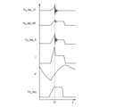
- FIG. 9 shows a torque command value Tq_req input to the control system, the vehicle speed V of the electric vehicle 1, the detected value I_b of the output current of the battery 21, and the Detected value Tq_det_LF of drive torque transmitted to the left front wheel, detected value Tq_det_RF of drive torque transmitted to the right front wheel, and sum Tq_det_tl of the left and right drive torques are shown.
- the horizontal axis indicates time t.
- control system 10 since the control system 10 according to the present embodiment includes the force sensor 11, an abnormality in the control parameters that cannot be detected by simply comparing the torque command value Tq_req, the detection value of the force sensor 11, and the detection value of the current sensor 25 can be determined. Therefore, it is possible to detect not only an abnormality occurring in each component of the control system 10 but also an abnormality in the control parameters for controlling the drive motor 7 .
- control device 50 can correct the target supply current I_tgt to the drive motor 7 according to the deviation between the reference torque-current characteristics and the actual torque-current characteristics. As a result, even when there is an abnormality in the control parameter, it is possible to output the drive torque according to the torque command value Tq_req, thereby reducing the discomfort felt by the driver.
Abstract
Provided are: a control device for an electric vehicle, the device being capable of determining any abnormalities in control parameters for a drive motor; an electric vehicle; and a recording medium on which a computer program is recorded. The control device for an electric vehicle acquires a detected value of battery output current detected by first sensor and a detected value of drive torque transmitted to vehicle wheels detected by second sensor, calculates an actual torque-current characteristic indicating the relationship between a current supplied to an inverter circuit and the drive torque transmitted to the vehicle wheels, and determines deviation between the calculated actual torque-current characteristic and a reference torque-current characteristic obtained by setting the relationship between a torque command value for the drive motor and a target supply current for the drive motor in advance.
Description
本開示は、電動車両の制御装置及び電動車両並びにコンピュータプログラムを記録した記録媒体に関する。
The present disclosure relates to an electric vehicle control device, an electric vehicle, and a recording medium recording a computer program.
近年、ハイブリッド電気自動車や純電気自動車に見られるように自動車の電動化が進んでいる。電動車両は、駆動力を出力する駆動用モータ及び当該駆動用モータを駆動するインバータを備えている。このような電動車両では、駆動用モータやインバータ、あるいはこれらの周辺機器のエラーを検知するシステムが必要である。
In recent years, the electrification of automobiles is progressing, as seen in hybrid electric vehicles and pure electric vehicles. An electric vehicle includes a driving motor that outputs driving force and an inverter that drives the driving motor. Such electric vehicles require a system for detecting errors in drive motors, inverters, or peripheral devices thereof.
例えば特許文献1には、駆動源にモータ/ジェネレータを備えたハイブリッド車両の制御装置であって、モータ/ジェネレータに供給するモータ電流の制御をモータ指令トルクに基づいて行うモータ電流フィードバック制御回路と、モータ指令トルクとモータトルクの乖離トルクに基づいてモータ制御系の故障を検知するモータ制御系故障検知回路とを設けた制御装置が開示されている。特許文献1の制御装置は、乖離トルクの故障判定値と、故障判定値を超えた状態を継続する故障判定時間とに基づいてモータトルク乖離故障を判定するように構成されている。
For example, Patent Document 1 discloses a control device for a hybrid vehicle having a motor/generator as a drive source, which includes a motor current feedback control circuit that controls the motor current supplied to the motor/generator based on the motor command torque, A control device is disclosed that is provided with a motor control system failure detection circuit that detects a failure of the motor control system based on the divergence torque between the motor command torque and the motor torque. The control device of Patent Literature 1 is configured to determine a motor torque divergence failure based on a failure determination value of torque divergence and a failure determination time during which the state exceeding the failure determination value continues.
上記特許文献1に記載の制御装置による故障検知機能は、駆動用モータに要求されるトルク指示値と、インバータから駆動用モータに供給されたモータ電流から求められる駆動用モータの出力トルクとの差の絶対値である乖離トルクを用いて駆動用モータの制御系の故障を検知するものである。つまり、当該故障検知機能は、駆動用モータに対して、トルク指令値に対応する電流が適切に供給されているかを判定している。
The failure detection function by the control device described in Patent Document 1 is the difference between the torque instruction value required for the drive motor and the output torque of the drive motor obtained from the motor current supplied to the drive motor from the inverter. The deviation torque, which is the absolute value of , is used to detect the failure of the control system of the driving motor. That is, the failure detection function determines whether a current corresponding to the torque command value is appropriately supplied to the driving motor.
しかしながら、駆動用モータの制御系の異常は、部品の異常あるいは制御パラメータの異常等様々な要因により発生し得るため、駆動用モータに対して適切な電流が供給されていたとしても、駆動用モータから出力される駆動トルクがトルク指令値に対応する適切なトルクとならないことがある。特許文献1の制御装置による故障検知機能では、駆動用モータからトルク指令値に対応する適切な駆動トルクが出力されているかを判断することができない。一方、トルク指令値と、駆動用モータから出力される駆動トルクを比較するだけでは、駆動用モータの制御に用いられている制御パラメータと駆動用モータから適切な駆動トルクを出力させ得る制御パラメータとのずれを把握することができない。
However, since an abnormality in the control system of the drive motor can occur due to various factors such as an abnormality in parts or an abnormality in control parameters, even if an appropriate current is supplied to the drive motor, the drive motor The drive torque output from may not be an appropriate torque corresponding to the torque command value. With the failure detection function of the control device of Patent Document 1, it cannot be determined whether or not the drive motor is outputting an appropriate drive torque corresponding to the torque command value. On the other hand, only by comparing the torque command value and the drive torque output from the drive motor, it is difficult to determine which control parameter is used to control the drive motor and which allows the drive motor to output an appropriate drive torque. It is not possible to grasp the deviation of
本開示は、上記問題に鑑みてなされたものであり、本開示の目的とするところは、駆動用モータの制御パラメータの異常を判定可能な電動車両の制御装置及び電動車両並びにコンピュータプログラムを記録した記録媒体を提供することにある。
The present disclosure has been made in view of the above problems, and an object of the present disclosure is to record an electric vehicle control device, an electric vehicle, and a computer program capable of determining an abnormality in a control parameter of a driving motor. It is to provide a recording medium.
上記課題を解決するために、本開示のある観点によれば、駆動トルクを出力する少なくとも一つの駆動用モータ、及び、駆動用モータを駆動するインバータ回路を備えた電動車両の制御システムに適用される電動車両の制御装置であって、一つ又は複数のプロセッサと、プロセッサと通信可能に接続された一つ又は複数のメモリと、を備え、プロセッサは、第1センサにより検出されるバッテリの出力電流の検出値と、第2センサにより検出される車輪に伝達される駆動トルクの検出値と、を取得し、インバータ回路への供給電流と車輪に伝達される駆動トルクとの関係を示す実トルク-電流特性を算出し、あらかじめ駆動用モータのトルク指示値と駆動用モータへの目標供給電流との関係を設定した基準トルク-電流特性と、算出した実トルク-電流特性と、のずれを判定する電動車両の制御装置が提供される。
In order to solve the above problems, according to one aspect of the present disclosure, the present invention is applied to an electric vehicle control system including at least one driving motor that outputs driving torque and an inverter circuit that drives the driving motor. A control device for an electric vehicle, comprising: one or more processors; and one or more memories communicatively connected to the processors, wherein the processors detect battery output detected by a first sensor Acquiring the detected value of the current and the detected value of the driving torque transmitted to the wheels detected by the second sensor, and obtaining the actual torque indicating the relationship between the current supplied to the inverter circuit and the driving torque transmitted to the wheels - Calculate the current characteristics, and determine the difference between the reference torque-current characteristics, which is the relationship between the torque command value of the drive motor and the target supply current to the drive motor, and the calculated actual torque-current characteristics. A control device for an electric vehicle is provided.
また、上記課題を解決するために、本開示の別の観点によれば、駆動トルクを出力する少なくとも一つの駆動用モータ、及び、駆動用モータを駆動するインバータ回路を備えた電動車両の制御システムに適用される電動車両の制御装置であって、第1センサにより検出されるバッテリの出力電流の検出値、及び、第2センサにより検出される車輪に伝達される駆動トルクの検出値を取得する取得部と、バッテリの出力電流と車輪に伝達される駆動トルクとの関係を示すトルク-電流特性を算出するトルク-電流特性算出部と、あらかじめ設定された基準トルク-電流特性とトルク-電流特性とのずれを判定する判定部と、を備えた電動車両の制御装置が提供される。
Further, in order to solve the above problems, according to another aspect of the present disclosure, a control system for an electric vehicle including at least one driving motor that outputs driving torque and an inverter circuit that drives the driving motor A control device for an electric vehicle applied to a vehicle, which obtains a detection value of the output current of the battery detected by a first sensor and a detection value of the driving torque transmitted to the wheels detected by the second sensor an acquisition unit, a torque-current characteristic calculation unit that calculates a torque-current characteristic indicating the relationship between the output current of the battery and the drive torque transmitted to the wheels, and preset reference torque-current characteristics and torque-current characteristics. and a determination unit that determines a deviation from the electric vehicle control device.
また、上記課題を解決するために、本開示のさらに別の観点によれば、駆動トルクを出力する少なくとも一つの駆動用モータ、駆動用モータを駆動するインバータ回路、及び車輪に作用する力を検出する力センサを備えた電動車両の制御システムを搭載した電動車両であって、電動車両の制御システムを制御する制御装置は、一つ又は複数のプロセッサと、プロセッサと通信可能に接続された一つ又は複数のメモリと、を備え、プロセッサは、第1センサにより検出されるバッテリの出力電流の検出値と、第2センサにより検出される車輪に伝達される駆動トルクの検出値と、を取得し、バッテリの出力電流と車輪に伝達される駆動トルクとの関係を示すトルク-電流特性を算出し、あらかじめ設定された基準トルク-電流特性とトルク-電流特性とのずれを判定する電動車両が提供される。
In order to solve the above problems, according to still another aspect of the present disclosure, at least one drive motor that outputs a drive torque, an inverter circuit that drives the drive motor, and force acting on the wheels are detected. An electric vehicle equipped with an electric vehicle control system having a force sensor, wherein a control device for controlling the electric vehicle control system comprises one or more processors and one processor communicably connected to the processor or a plurality of memories, wherein the processor acquires the detected value of the battery output current detected by the first sensor and the detected value of the drive torque transmitted to the wheel detected by the second sensor. , an electric vehicle that calculates a torque-current characteristic that indicates the relationship between the output current of the battery and the drive torque transmitted to the wheels, and determines the deviation between the preset reference torque-current characteristic and the torque-current characteristic. be done.
また、上記課題を解決するために、本開示のさらに別の観点によれば、駆動トルクを出力する少なくとも一つの駆動用モータ、及び、駆動用モータを駆動するインバータ回路を備えた電動車両の制御システムに適用されるコンピュータプログラムを記録した記録媒体であって、一つ又は複数のプロセッサに、第1センサにより検出されるバッテリの出力電流の検出値と、第2センサにより検出される車輪に伝達される駆動トルクの検出値と、を取得することと、インバータ回路への供給電流と車輪に伝達される駆動トルクとの関係を示す実トルク-電流特性を算出することと、あらかじめ駆動用モータのトルク指示値と駆動用モータへの目標供給電流との関係を設定した基準トルク-電流特性と、算出した実トルク-電流特性と、のずれを判定することと、を含む処理を実行させるコンピュータプログラムを記録した記録媒体が提供される。
Further, in order to solve the above problems, according to still another aspect of the present disclosure, control of an electric vehicle including at least one drive motor that outputs drive torque and an inverter circuit that drives the drive motor A recording medium recording a computer program applied to the system, which transmits to one or more processors the detection value of the battery output current detected by the first sensor and the wheel detected by the second sensor calculating the actual torque-current characteristic indicating the relationship between the current supplied to the inverter circuit and the driving torque transmitted to the wheels; A computer program for executing a process including determining a difference between a reference torque-current characteristic that sets a relationship between a torque instruction value and a target supply current to a drive motor and a calculated actual torque-current characteristic. is provided.
以上説明したように本開示によれば、駆動用モータの制御パラメータの異常を判定することができる。
As described above, according to the present disclosure, it is possible to determine whether the control parameters of the drive motor are abnormal.
以下、添付図面を参照しながら、本開示の好適な実施の形態について詳細に説明する。なお、本明細書及び図面において、実質的に同一の機能構成を有する構成要素については、同一の符号を付することにより重複説明を省略する。
Hereinafter, preferred embodiments of the present disclosure will be described in detail with reference to the accompanying drawings. In the present specification and drawings, constituent elements having substantially the same functional configuration are denoted by the same reference numerals, thereby omitting redundant description.
<1.電動車両の構成>
まず、本開示の実施の形態に係る電動車両の診断装置を含む制御システムを備えた電動車両の構成の一例を説明する。 <1. Configuration of electric vehicle>
First, an example configuration of an electric vehicle including a control system including an electric vehicle diagnostic apparatus according to an embodiment of the present disclosure will be described.
まず、本開示の実施の形態に係る電動車両の診断装置を含む制御システムを備えた電動車両の構成の一例を説明する。 <1. Configuration of electric vehicle>
First, an example configuration of an electric vehicle including a control system including an electric vehicle diagnostic apparatus according to an embodiment of the present disclosure will be described.
図1は、制御システム10を備えた電動車両1の構成例を示す模式図である。図1に示した電動車両1は、四つの車輪3を備えた四輪自動車である。電動車両1は、四輪自動車に限られるものではなく、二輪自動車やバス、トラック等の商用車をはじめとする他の車両であってもよい。
FIG. 1 is a schematic diagram showing a configuration example of an electric vehicle 1 equipped with a control system 10. FIG. An electric vehicle 1 shown in FIG. 1 is a four-wheeled vehicle having four wheels 3 . The electric vehicle 1 is not limited to a four-wheeled vehicle, and may be other vehicles including commercial vehicles such as two-wheeled vehicles, buses, and trucks.
なお、図1では、4つの車輪3やそれぞれの車輪3に対して設けられた駆動用モータ7及び力センサ11等については、符号の末尾に添字LF(左前)、RF(右前)、LR(左後)及びRR(右後)が付されている。また、以下の説明において、特に区別を要する場合以外には、適宜添字LF,RF,LR及びRRを省略する。
In FIG. 1, the four wheels 3 and the drive motors 7 and force sensors 11 provided for the respective wheels 3 are indicated by the suffixes LF (left front), RF (right front), LR ( left rear) and RR (right rear). Also, in the following description, the suffixes LF, RF, LR, and RR are omitted as appropriate, unless otherwise required.
電動車両1の制御システム10は、力センサ11、駆動用モータ7、インバータユニット30、バッテリユニット20及び制御装置50を備えている。制御システム10は、バッテリユニット20内のバッテリ21に蓄積された電力を駆動用モータ7へ供給し、駆動用モータ7から出力される駆動トルクを車輪3に伝達することで電動車両1を走行させる。
The control system 10 of the electric vehicle 1 includes a force sensor 11, a drive motor 7, an inverter unit 30, a battery unit 20 and a control device 50. The control system 10 supplies electric power accumulated in the battery 21 in the battery unit 20 to the driving motor 7, and transmits the driving torque output from the driving motor 7 to the wheels 3, thereby causing the electric vehicle 1 to run. .
バッテリユニット20は、バッテリ21、バッテリ管理装置23及び電流センサ25を備えている。バッテリ21は、充放電可能な二次電池である。例えばバッテリ21は、定格出力が200Vのリチウムイオンバッテリであってよいが、バッテリ21の種類や定格出力は特に限定されない。バッテリ21は、インバータユニット30を介して駆動用モータ7に接続され、駆動用モータ7に供給される電力を蓄積する。電流センサ25は、バッテリ21の出力電流を検出する。電流センサ25は、本開示の技術における第1センサに相当する。この他、バッテリユニット20には、バッテリ21の出力電圧を検出する電圧センサ及びバッテリ21の温度を検出する温度センサが設けられている。バッテリ管理装置23は、バッテリ21の開放電圧、出力電圧、出力電流及びバッテリ温度等を取得し、これらの情報を制御装置50へ送信する。
The battery unit 20 includes a battery 21 , a battery management device 23 and a current sensor 25 . The battery 21 is a rechargeable secondary battery. For example, the battery 21 may be a lithium-ion battery with a rated output of 200V, but the type and rated output of the battery 21 are not particularly limited. The battery 21 is connected to the driving motor 7 via the inverter unit 30 and accumulates power supplied to the driving motor 7 . Current sensor 25 detects the output current of battery 21 . The current sensor 25 corresponds to the first sensor in the technique of the present disclosure. In addition, the battery unit 20 is provided with a voltage sensor that detects the output voltage of the battery 21 and a temperature sensor that detects the temperature of the battery 21 . The battery management device 23 acquires the open-circuit voltage, output voltage, output current, battery temperature, and the like of the battery 21 and transmits this information to the control device 50 .
駆動用モータ7は、車軸5を介して車輪3に接続され、車輪3に伝達する駆動トルクを出力する。駆動用モータ7は、例えば三相交流式のラジアルモータあるいはアキシャルギャップモータであってよいが、相数やモータの種類は特に限定されない。駆動用モータ7は、電動車両1の減速時に車輪3側からの回転トルクを受けて回生発電を行い、制動力を発生させる機能を有する。
The drive motor 7 is connected to the wheels 3 via the axle 5 and outputs drive torque to be transmitted to the wheels 3 . The driving motor 7 may be, for example, a three-phase AC radial motor or an axial gap motor, but the number of phases and the type of motor are not particularly limited. The driving motor 7 has a function of receiving rotational torque from the wheel 3 side during deceleration of the electric vehicle 1 and performing regenerative power generation to generate braking force.
本実施形態に係る電動車両1では、一つの車輪3に対して一つの駆動用モータ7が接続されているが、左前輪3LF及び右前輪3RFに駆動トルクを伝達する前輪駆動用モータ、及び、左後輪3LR及び右後輪3RRに駆動トルクを伝達する後輪駆動用モータの二つの駆動用モータを備えた電動車両1であってもよい。また、四つの車輪3に駆動トルクを伝達する一つの駆動用モータを備えた電動車両1であってもよい。一つの駆動用モータから複数の車輪3に対して駆動トルクを伝達する構成の場合、左右の車軸の間、あるいは、前後の駆動軸の間に差動機構が設けられていてもよい。
In the electric vehicle 1 according to the present embodiment, one drive motor 7 is connected to one wheel 3. A front wheel drive motor that transmits drive torque to the left front wheel 3LF and the right front wheel 3RF, and The electric vehicle 1 may be provided with two drive motors, a rear wheel drive motor that transmits drive torque to the left rear wheel 3LR and the right rear wheel 3RR. Alternatively, the electric vehicle 1 may include one drive motor that transmits drive torque to the four wheels 3 . In the case of a configuration in which drive torque is transmitted from one drive motor to a plurality of wheels 3, a differential mechanism may be provided between the left and right axles or between the front and rear drive shafts.
各車輪3には、車輪3に対して作用する力を検出する力センサ11が設けられている。力センサ11は、少なくとも駆動用モータ7から出力されて車輪3に伝達される駆動トルク(回転トルク)又は車両前後方向の駆動力(駆動力)を検出可能に構成されている。力センサ11は、本開示の技術における第2センサに相当する。例えば力センサ11は、車輪3を支持する車軸5に作用するx方向(車軸の軸方向及び車高方向に直交する方向)、y方向(車軸の軸方向)及びz方向(車高方向)の分力、並びに、x方向、y方向及びz方向それぞれの軸回りのモーメントを検出するセンサであってよい。この場合、y方向の軸回りのモーメントが、駆動用モータ7から出力される駆動トルクに相当する。また、x方向の分力が、車輪3の駆動力に相当する。ただし、力センサ11の種類は限定されない。例えば力センサ11は、車輪3のホイールに作用する回転トルクを検出するセンサであってもよい。力センサ11から出力されるセンサ信号は、制御装置50に入力される。
Each wheel 3 is provided with a force sensor 11 that detects force acting on the wheel 3 . The force sensor 11 is configured to detect at least the driving torque (rotational torque) output from the driving motor 7 and transmitted to the wheels 3 or the driving force (driving force) in the longitudinal direction of the vehicle. The force sensor 11 corresponds to the second sensor in the technique of the present disclosure. For example, the force sensor 11 detects the force acting on the axle 5 that supports the wheels 3 in the x direction (the axial direction of the axle and the direction perpendicular to the vehicle height direction), the y direction (the axial direction of the axle), and the z direction (the vehicle height direction). It may be a sensor that detects component forces and moments about axes in the x-, y-, and z-directions. In this case, the moment about the axis in the y direction corresponds to the drive torque output from the drive motor 7 . Further, the component force in the x direction corresponds to the driving force of the wheels 3 . However, the type of force sensor 11 is not limited. For example, the force sensor 11 may be a sensor that detects rotational torque acting on the wheels of the wheels 3 . A sensor signal output from the force sensor 11 is input to the control device 50 .
インバータユニット30は、それぞれの駆動用モータ7LF,7RF,7LR,7RRへ電力を供給するインバータ回路31LF,31RF,31LR,31RRを含んで構成される。それぞれのインバータ回路31は、バッテリ21から掃引される直流電力を三相交流の電力に変換して駆動用モータ7に供給する。また、インバータ回路31は、駆動用モータ7により回生発電される三相交流の電力を直流電力に変換し、バッテリ21へ供給する。インバータユニット30は、昇降圧回路を含んでいてもよい。インバータユニット30の駆動は、制御装置50により制御される。
The inverter unit 30 includes inverter circuits 31LF, 31RF, 31LR, and 31RR that supply power to the respective drive motors 7LF, 7RF, 7LR, and 7RR. Each inverter circuit 31 converts DC power swept from the battery 21 into three-phase AC power and supplies it to the driving motor 7 . The inverter circuit 31 also converts the three-phase AC power regenerated by the drive motor 7 into DC power and supplies the DC power to the battery 21 . The inverter unit 30 may include a step-up/step-down circuit. Driving of the inverter unit 30 is controlled by the control device 50 .
制御装置50は、一つ又は複数のプロセッサがコンピュータプログラムを実行することで制御システム10を診断する装置として機能する。また、本実施形態の制御装置50は、力センサ11のセンサ信号を取得して信号処理を行う機能、アクセルペダル8の操作量及びステアリングホイール6の操舵角を取得してトルク指示値を計算する機能、バッテリ管理装置23からバッテリ21の出力電圧及び出力電流等の情報を取得し制御システム10の電力を管理する機能、及び、トルク指示値に基づいてインバータユニット30の駆動を制御する機能を有する。制御装置50は、これらの複数の機能を実現な一つの装置としてユニット化されていてもよく、互いに通信可能に接続された複数の装置により構成されていてもよい。
The control device 50 functions as a device that diagnoses the control system 10 by one or more processors executing a computer program. Further, the control device 50 of the present embodiment has a function of acquiring a sensor signal of the force sensor 11 and performing signal processing, acquiring an operation amount of the accelerator pedal 8 and a steering angle of the steering wheel 6, and calculating a torque instruction value. function, a function of acquiring information such as the output voltage and output current of the battery 21 from the battery management device 23 to manage the power of the control system 10, and a function of controlling the driving of the inverter unit 30 based on the torque instruction value. . The control device 50 may be unitized as one device capable of realizing these multiple functions, or may be configured by a plurality of devices communicably connected to each other.
コンピュータプログラムは、制御装置50が実行すべき後述する動作をCPU(Central Processing Unit)等のプロセッサに実行させるためのコンピュータプログラムである。プロセッサにより実行されるコンピュータプログラムは、制御装置50に備えられた記憶部(メモリ)53として機能する記録媒体に記録されていてもよく、制御装置50に内蔵された記録媒体又は制御装置50に外付け可能な任意の記録媒体に記録されていてもよい。
The computer program is a computer program for causing a processor such as a CPU (Central Processing Unit) to execute operations to be executed by the control device 50, which will be described later. The computer program executed by the processor may be recorded in a recording medium functioning as a storage unit (memory) 53 provided in the control device 50, or may be stored in a recording medium built in the control device 50 or external to the control device 50. may be recorded on any recording medium that can be attached.
コンピュータプログラムを記録する記録媒体としては、ハードディスク、フロッピーディスク及び磁気テープ等の磁気媒体、CD-ROM(Compact Disk Read Only Memory)、DVD(Digital Versatile Disk)及びBlu-ray(登録商標)等の光記録媒体、フロプティカルディスク等の磁気光媒体、ROM(Read Only Memory)及びRAM(Random Access Memory)等の記憶素子、並びにSSD(Solid State Drive)及びUSB(Universal Serial Bus)メモリ等のフラッシュメモリ、その他のプログラムを格納可能な媒体であってよい。
Recording media for recording computer programs include magnetic media such as hard disks, floppy disks and magnetic tapes, optical media such as CD-ROMs (Compact Disk Read Only Memory), DVDs (Digital Versatile Disks) and Blu-ray (registered trademark). Recording media, magneto-optical media such as floptical disks, storage elements such as ROM (Read Only Memory) and RAM (Random Access Memory), and flash memory such as SSD (Solid State Drive) and USB (Universal Serial Bus) memory , and other programs.
<2.制御装置>
ここまで、電動車両1及び制御システム10の構成例を説明した。以下、制御装置50について詳しく説明する。 <2. Control device>
So far, configuration examples of theelectric vehicle 1 and the control system 10 have been described. The control device 50 will be described in detail below.
ここまで、電動車両1及び制御システム10の構成例を説明した。以下、制御装置50について詳しく説明する。 <2. Control device>
So far, configuration examples of the
(2-1.概略)
まず、制御装置50が実行する処理の概略を説明する。
一般に、車両には多数の制御装置が搭載され、それぞれの制御装置は、各制御装置が司るモジュールの異常を出力電流や出力電圧等に基づいて検知する自己診断機能を備えている。電動車両の制御システムでは、インバータユニット及び駆動用モータの制御を司る制御装置がこれらのモジュールの異常診断機能を備えている、当該異常診断機能に不具合がある場合には、少なくとも安全性能に直結する異常を他の制御装置によっても検知できるように二重化することが必要になる。 (2-1. Overview)
First, an outline of the processing executed by thecontrol device 50 will be described.
In general, a vehicle is equipped with a large number of control devices, and each control device has a self-diagnostic function that detects an abnormality in a module controlled by each control device based on output current, output voltage, and the like. In the electric vehicle control system, the control device that controls the inverter unit and the drive motor is equipped with an abnormality diagnosis function for these modules. Duplication is required so that the abnormality can be detected by other control devices.
まず、制御装置50が実行する処理の概略を説明する。
一般に、車両には多数の制御装置が搭載され、それぞれの制御装置は、各制御装置が司るモジュールの異常を出力電流や出力電圧等に基づいて検知する自己診断機能を備えている。電動車両の制御システムでは、インバータユニット及び駆動用モータの制御を司る制御装置がこれらのモジュールの異常診断機能を備えている、当該異常診断機能に不具合がある場合には、少なくとも安全性能に直結する異常を他の制御装置によっても検知できるように二重化することが必要になる。 (2-1. Overview)
First, an outline of the processing executed by the
In general, a vehicle is equipped with a large number of control devices, and each control device has a self-diagnostic function that detects an abnormality in a module controlled by each control device based on output current, output voltage, and the like. In the electric vehicle control system, the control device that controls the inverter unit and the drive motor is equipped with an abnormality diagnosis function for these modules. Duplication is required so that the abnormality can be detected by other control devices.
電動車両の制御システムでは、電動車両に対する加速要求を表すトルク指示値が制御系への入力であり、車輪に対して伝達される駆動トルクが制御系からの出力である。制御システムにおいて、制御系の入力と出力との間に介在する要素は「通信」、「インバータユニット30」、「駆動用モータ7」及び「バッテリ21」であり、これらのどこかに発生した異常を検知可能な確度の高い機能が求められる。
In an electric vehicle control system, a torque instruction value representing an acceleration request for an electric vehicle is an input to the control system, and a driving torque transmitted to the wheels is an output from the control system. In the control system, the elements intervening between the input and output of the control system are "communication", "inverter unit 30", "drive motor 7" and "battery 21". A highly accurate function that can detect
例えば電動車両に力センサが備えられていない制御システムにおいて、インバータユニット及び駆動用モータの制御を司る制御装置は、「異常無し」、「インバータユニットの異常」、「駆動用モータの異常」及び「駆動用モータの回転数」をモニタする。また、バッテリユニットの制御を司るバッテリ管理装置は、「バッテリの異常」及び「バッテリの出力電流」をモニタする。また、電動車両のトルク指示値の演算を司る制御装置は、「トルク指示値」をモニタする。
For example, in a control system in which an electric vehicle is not equipped with a force sensor, a control device that controls the inverter unit and the driving motor can read "no abnormality", "abnormality of the inverter unit", "abnormality of the driving motor", and " Monitor the number of revolutions of the drive motor. Also, the battery management device that controls the battery unit monitors "battery abnormality" and "battery output current". Further, the control device that manages the calculation of the torque instruction value of the electric vehicle monitors the "torque instruction value".
ここで、それぞれの制御装置において異常が検知されていない状況で、トルク指示値に対するバッテリの出力電流及び駆動用モータの回転数をモニタしたとしても、トルク指示値の入力に対する出力として駆動用モータの回転数をモニタすることは適切ではない。このため、トルク指示値に対して適切なバッテリの出力電流値を判定することができない。したがって、インバータユニット及び駆動用モータの異常診断を二重化するには、トルク指示値がゼロでない場合にバッテリの出力電流値がゼロになっていないかという基準で判定するしかできないことになる。これではトルク指示値がゼロではなく、バッテリの出力電流値がゼロでないとしても、駆動用モータが回転しているか否かにかかわらず、インバータユニット及び駆動用モータの異常を検知することができない。言うまでもなく、インバータユニットの制御パラメータの異常を検知することもできない。
Here, even if the output current of the battery and the number of rotations of the driving motor are monitored with respect to the torque instruction value in a situation where no abnormality is detected in each control device, the output of the driving motor in response to the input of the torque instruction value is Monitoring the number of revolutions is not appropriate. Therefore, it is not possible to determine an appropriate battery output current value for the torque instruction value. Therefore, in order to double the abnormality diagnosis of the inverter unit and the drive motor, it is only possible to determine whether the output current value of the battery is zero when the torque instruction value is not zero. In this case, even if the torque command value is not zero and the output current value of the battery is not zero, it is impossible to detect an abnormality in the inverter unit and the drive motor regardless of whether the drive motor is rotating. Needless to say, an abnormality in the control parameters of the inverter unit cannot be detected either.
図2は、力センサを備えていない制御システムにおいて、トルク指示値とバッテリの出力電流値しか検出できない場合であって、それぞれのモジュールを司る制御装置が自己診断による異常を検知していない場合における、異常を判別するための診断表を示す。制御系の出力である車輪に伝達される駆動トルクを検出することができない場合、トルク指示値がゼロではないにもかかわらずバッテリの出力電流がゼロになっているのであれば、それぞれの自己診断による異常が検知されていないことから、制御装置間の通信系の異常と判定することができる(No.2)。一方、トルク指示値及びバッテリの出力電流がともにゼロでない場合あるいはともにゼロである場合、システム全体としていずれかの箇所に異常があるとしても、車輪に伝達される駆動トルクが適切であるか不明であることから異常を検知することができない(No.1及び3)。この場合、簡易診断結果は「異常無し」となる。
FIG. 2 shows a control system that does not have a force sensor and can detect only the torque instruction value and the battery output current value, and the control device that controls each module does not detect an abnormality by self-diagnosis. , shows a diagnostic table for determining anomalies. If the drive torque transmitted to the wheels, which is the output of the control system, cannot be detected, and if the output current of the battery is zero even though the torque indication value is not zero, each self-diagnosis Since no abnormality has been detected by the controller, it can be determined that there is an abnormality in the communication system between the control devices (No. 2). On the other hand, if both the torque instruction value and the battery output current are not zero or both are zero, even if there is an abnormality in some part of the system as a whole, it is unclear whether the drive torque transmitted to the wheels is appropriate. Therefore, an abnormality cannot be detected (Nos. 1 and 3). In this case, the simple diagnosis result is "no abnormality".
これに対して、本実施形態に係る電動車両1の制御システム10は、制御系の出力である、車輪3に伝達される駆動トルクを検出可能な力センサ(第2センサ)11を備えている。制御装置50は、当該力センサ11により検出される駆動トルクの情報を用いることにより、制御システム10の異常診断が二重化される。特に、制御装置50は、駆動用モータ7の駆動を制御するための制御パラメータの異常を検知することが可能となる。
On the other hand, the control system 10 of the electric vehicle 1 according to the present embodiment includes a force sensor (second sensor) 11 capable of detecting the drive torque transmitted to the wheels 3, which is the output of the control system. . The control device 50 doubles abnormality diagnosis of the control system 10 by using the information of the drive torque detected by the force sensor 11 . In particular, the control device 50 can detect an abnormality in a control parameter for controlling driving of the drive motor 7 .
(2-2.制御装置の構成)
図3は、制御装置50の構成の一例を示すブロック図である。制御装置50は、一つ又は複数のプロセッサと、当該プロセッサと通信可能に接続されたRAM又はROM等の一つ又は複数のメモリを備えて構成される。制御装置50の一部又は全部は、ファームウェア等の更新可能なもので構成されてもよく、また、プロセッサからの指令によって実行されるプログラムモジュール等であってもよい。 (2-2. Configuration of control device)
FIG. 3 is a block diagram showing an example of the configuration of thecontrol device 50. As shown in FIG. The control device 50 includes one or more processors and one or more memories such as RAM or ROM communicably connected to the processors. A part or all of the control device 50 may be composed of firmware or the like that can be updated, or may be a program module or the like that is executed by instructions from a processor.
図3は、制御装置50の構成の一例を示すブロック図である。制御装置50は、一つ又は複数のプロセッサと、当該プロセッサと通信可能に接続されたRAM又はROM等の一つ又は複数のメモリを備えて構成される。制御装置50の一部又は全部は、ファームウェア等の更新可能なもので構成されてもよく、また、プロセッサからの指令によって実行されるプログラムモジュール等であってもよい。 (2-2. Configuration of control device)
FIG. 3 is a block diagram showing an example of the configuration of the
制御装置50には、各車輪3に設けられた力センサ11が接続されている。また、制御装置50には、アクセルペダル8の操作量を検出するアクセルペダルセンサ8a及びステアリングホイール6の操舵角を検出する舵角センサ6aが接続されている。さらに、制御装置50には、バッテリ管理装置23及びインバータユニット30が接続されている。制御装置50とそれぞれの機器は、専用線又はCAN(Controller Area Network)等の通信バスを介して接続される。
A force sensor 11 provided on each wheel 3 is connected to the control device 50 . An accelerator pedal sensor 8a for detecting the amount of operation of the accelerator pedal 8 and a steering angle sensor 6a for detecting the steering angle of the steering wheel 6 are connected to the control device 50 . Furthermore, the battery management device 23 and the inverter unit 30 are connected to the control device 50 . The control device 50 and each device are connected via a communication bus such as a dedicated line or a CAN (Controller Area Network).
制御装置50は、処理部51及び記憶部53を備える。処理部51は、指示トルク算出部61、バッテリ情報取得部63、力センサ出力検出部65、トルク出力制御部67及び診断部69を備えている。処理部51は、CPU等の一つ又は複数のプロセッサであり、指示トルク算出部61、バッテリ情報取得部63、力センサ出力検出部65、トルク出力制御部67及び診断部69の各部は、プロセッサによるコンピュータプログラムの実行により実現される機能である。ただし、指示トルク算出部61、バッテリ情報取得部63、力センサ出力検出部65、トルク出力制御部67及び診断部69の一部が、アナログ回路により構成されていてもよい。
The control device 50 includes a processing unit 51 and a storage unit 53. The processing unit 51 includes an instruction torque calculation unit 61 , a battery information acquisition unit 63 , a force sensor output detection unit 65 , a torque output control unit 67 and a diagnosis unit 69 . The processing unit 51 is one or a plurality of processors such as a CPU. It is a function realized by executing a computer program by However, part of the command torque calculation unit 61, the battery information acquisition unit 63, the force sensor output detection unit 65, the torque output control unit 67, and the diagnosis unit 69 may be configured by analog circuits.
記憶部53は、RAM又はROM等の一つ又は複数の記憶素子、あるいは、ハードディスク又はSSD等の記録媒体を含んで構成される。記憶部53は、処理部51により実行されるコンピュータプログラムやコンピュータプログラムの実行に用いられる種々のパラメータの他、取得されたデータ、演算結果のデータ等を記憶する。
The storage unit 53 includes one or more storage elements such as RAM or ROM, or a recording medium such as a hard disk or SSD. The storage unit 53 stores a computer program executed by the processing unit 51, various parameters used for executing the computer program, acquired data, calculation result data, and the like.
(2-2-1.指示トルク算出部)
指示トルク算出部61は、アクセルペダルセンサ8aから出力されるセンサ信号が示すアクセルペダル8の操作量に基づいてトルク指示値Tq_reqを算出する。例えば指示トルク算出部61は、アクセルペダルの操作量とトルク指示値との関係を示す指示トルクマップを参照して、アクセルペダル8の操作量に対応するトルク指示値Tq_reqを求める。ここで求められるトルク指示値Tq_reqは、四つの駆動用モータ7LF,7RF,7LR,7RRから出力させるトルク指示値Tq_req_LF,Tq_req_RF,Tq_req_LR,Tq_req_RRの和である。 (2-2-1. Instruction torque calculator)
The instructiontorque calculation unit 61 calculates the torque instruction value Tq_req based on the operation amount of the accelerator pedal 8 indicated by the sensor signal output from the accelerator pedal sensor 8a. For example, the command torque calculation unit 61 refers to a command torque map that indicates the relationship between the accelerator pedal operation amount and the torque command value, and obtains the torque command value Tq_req corresponding to the accelerator pedal 8 operation amount. The torque command value Tq_req obtained here is the sum of the torque command values Tq_req_LF, Tq_req_RF, Tq_req_LR and Tq_req_RR output from the four drive motors 7LF, 7RF, 7LR and 7RR.
指示トルク算出部61は、アクセルペダルセンサ8aから出力されるセンサ信号が示すアクセルペダル8の操作量に基づいてトルク指示値Tq_reqを算出する。例えば指示トルク算出部61は、アクセルペダルの操作量とトルク指示値との関係を示す指示トルクマップを参照して、アクセルペダル8の操作量に対応するトルク指示値Tq_reqを求める。ここで求められるトルク指示値Tq_reqは、四つの駆動用モータ7LF,7RF,7LR,7RRから出力させるトルク指示値Tq_req_LF,Tq_req_RF,Tq_req_LR,Tq_req_RRの和である。 (2-2-1. Instruction torque calculator)
The instruction
また、指示トルク算出部61は、各駆動用モータ7LF,7RF,7LR,7RRに対してトルク指示値Tq_reqを配分し、各駆動用モータ7LF,7RF,7LR,7RRから出力させるトルク指示値Tq_req_LF,Tq_req_RF,Tq_req_LR,Tq_req_RRを算出する。本実施形態の電動車両1は、各車輪3に対して一つの駆動用モータ7が設けられている。このため、指示トルク算出部61は、旋回走行時に発生する内輪差あるいは外輪差の影響、さらにはオーバーステアあるいはアンダーステアの影響が小さくなるように、駆動用モータ7ごとにトルク指示値Tq_req_LF,Tq_req_RF,Tq_req_LR,Tq_req_RRを算出する。
In addition, the instruction torque calculation unit 61 distributes the torque instruction value Tq_req to each of the drive motors 7LF, 7RF, 7LR, and 7RR, and the torque instruction values Tq_req_LF, Tq_req_LF, and Calculate Tq_req_RF, Tq_req_LR, and Tq_req_RR. The electric vehicle 1 of this embodiment is provided with one driving motor 7 for each wheel 3 . Therefore, the instruction torque calculation unit 61 calculates the torque instruction values Tq_req_LF, Tq_req_RF, Calculate Tq_req_LR and Tq_req_RR.
ただし、一つの前輪駆動用モータで左前輪3LF及び右前輪3RFを駆動する場合、一つの後輪駆動用モータで左後輪3LR及び右後輪3RRを駆動する場合、あるいは一つの駆動用モータで四つの車輪3を駆動する場合等、左右の車軸あるいは前後の駆動軸の間に差動機構が設けられている場合には、各駆動用モータに均等に駆動トルクを配分してもよい。また、電動車両1が自動運転可能な車両である場合、指示トルク算出部61は、自動運転を制御する制御装置が算出したトルク指示値Tq_reqに基づいて各駆動用モータ7のトルク指示値Tq_req_LF,Tq_req_RF,Tq_req_LR,Tq_req_RRを算出する。
However, when one front wheel drive motor drives the left front wheel 3LF and right front wheel 3RF, when one rear wheel drive motor drives the left rear wheel 3LR and right rear wheel 3RR, or when one drive motor drives When a differential mechanism is provided between the left and right axles or the front and rear drive shafts, such as when four wheels 3 are driven, the drive torque may be equally distributed to each drive motor. Further, when the electric vehicle 1 is a vehicle capable of automatic operation, the command torque calculation unit 61 calculates torque command values Tq_req_LF and Calculate Tq_req_RF, Tq_req_LR, and Tq_req_RR.
(2-2-2.バッテリ情報取得部)
バッテリ情報取得部63は、バッテリ管理装置23から送信されるバッテリ21の情報を取得する。バッテリ21の情報は、バッテリ21の開放電圧、出力電圧、出力電流及び温度の情報を含む。本実施形態では、バッテリ情報取得部63は、少なくとも電流センサ(第1センサ)25により検出されるバッテリ21の出力電流の検出値I_bの情報を取得する。 (2-2-2. Battery information acquisition unit)
The batteryinformation acquisition unit 63 acquires information on the battery 21 transmitted from the battery management device 23 . The information on the battery 21 includes information on the open circuit voltage, output voltage, output current and temperature of the battery 21 . In the present embodiment, the battery information acquisition unit 63 acquires at least information on the detected value I_b of the output current of the battery 21 detected by the current sensor (first sensor) 25 .
バッテリ情報取得部63は、バッテリ管理装置23から送信されるバッテリ21の情報を取得する。バッテリ21の情報は、バッテリ21の開放電圧、出力電圧、出力電流及び温度の情報を含む。本実施形態では、バッテリ情報取得部63は、少なくとも電流センサ(第1センサ)25により検出されるバッテリ21の出力電流の検出値I_bの情報を取得する。 (2-2-2. Battery information acquisition unit)
The battery
(2-2-3.力センサ出力検出部)
力センサ出力検出部65は、力センサ(第2センサ)11から出力されるセンサ信号に基づいて各車輪3に作用する力を検出する。例えば力センサ11が上述した6分力を検出するセンサである場合、力センサ出力検出部65は、力センサ11から出力されるxyz方向それぞれの分力及びxyz方向それぞれの軸回りに作用するモーメントを示すセンサ信号(電圧値)を取得する。力センサ出力検出部65は、センサ信号を増幅する増幅回路から出力される信号を取得するように構成されていてもよい。力センサ出力検出部65は、少なくとも駆動用モータ7から出力された駆動トルクTq_detに相当するy方向の軸回りに作用するモーメントを検出する。また、本実施形態では、力センサ出力検出部65は、車輪3の駆動力F_detに相当するx方向の分力を検出する。 (2-2-3. Force sensor output detector)
The force sensoroutput detection section 65 detects the force acting on each wheel 3 based on the sensor signal output from the force sensor (second sensor) 11 . For example, when the force sensor 11 is a sensor that detects the six component forces described above, the force sensor output detection unit 65 detects the component force in each of the xyz directions output from the force sensor 11 and the moment acting around each axis in the xyz direction. Acquire a sensor signal (voltage value) indicating The force sensor output detection section 65 may be configured to acquire a signal output from an amplifier circuit that amplifies the sensor signal. The force sensor output detection unit 65 detects at least a moment acting around the axis in the y direction corresponding to the drive torque Tq_det output from the drive motor 7 . Further, in the present embodiment, the force sensor output detection unit 65 detects an x-direction force component corresponding to the driving force F_det of the wheels 3 .
力センサ出力検出部65は、力センサ(第2センサ)11から出力されるセンサ信号に基づいて各車輪3に作用する力を検出する。例えば力センサ11が上述した6分力を検出するセンサである場合、力センサ出力検出部65は、力センサ11から出力されるxyz方向それぞれの分力及びxyz方向それぞれの軸回りに作用するモーメントを示すセンサ信号(電圧値)を取得する。力センサ出力検出部65は、センサ信号を増幅する増幅回路から出力される信号を取得するように構成されていてもよい。力センサ出力検出部65は、少なくとも駆動用モータ7から出力された駆動トルクTq_detに相当するy方向の軸回りに作用するモーメントを検出する。また、本実施形態では、力センサ出力検出部65は、車輪3の駆動力F_detに相当するx方向の分力を検出する。 (2-2-3. Force sensor output detector)
The force sensor
(2-2-4.トルク出力制御部)
トルク出力制御部67は、各インバータ回路31LF,31RF,31LR,31RRの駆動を制御し、各駆動用モータ7LF,7RF,7LR,7RRの駆動(力行)及び回生を制御する。駆動用モータ7から駆動トルクを出力させる場合、トルク出力制御部67は、トルク指示値と供給電流との関係を示す基準トルク-電流特性マップの情報を参照して、指示トルク算出部61により求められたトルク指示値Tq_req_LF,Tq_req_RF,Tq_req_LR,Tq_req_RRに基づいて各駆動用モータ7LF,7RF,7LR,7RRの目標供給電流I_tgt_LF,I_tgt_RF,I_tgt_LR,I_tgt_RRを設定し、各インバータ回路31LF,31RF,31LR,31RRの駆動を制御する。これにより、それぞれの駆動用モータ7に対して三相交流電流が供給され、駆動用モータ7が駆動することによりそれぞれの車輪3に対して駆動トルクが出力される。 (2-2-4. Torque output control section)
The torqueoutput control unit 67 controls driving of the inverter circuits 31LF, 31RF, 31LR and 31RR, and controls driving (powering) and regeneration of the driving motors 7LF, 7RF, 7LR and 7RR. When driving torque is output from the drive motor 7, the torque output control unit 67 refers to the information of the reference torque-current characteristic map that indicates the relationship between the torque command value and the supply current, and the command torque calculation unit 61 obtains Based on the torque command values Tq_req_LF, Tq_req_RF, Tq_req_LR, Tq_req_RR obtained, the target supply currents I_tgt_LF, I_tgt_RF, I_tgt_LR, I_tgt_RR of the drive motors 7LF, 7RF, 7LR, 7RR are set, and the inverter circuits 31LF, 31RF, 31LR, It controls the driving of 31RR. As a result, a three-phase alternating current is supplied to each of the drive motors 7 , and drive torque is output to each of the wheels 3 by driving the drive motors 7 .
トルク出力制御部67は、各インバータ回路31LF,31RF,31LR,31RRの駆動を制御し、各駆動用モータ7LF,7RF,7LR,7RRの駆動(力行)及び回生を制御する。駆動用モータ7から駆動トルクを出力させる場合、トルク出力制御部67は、トルク指示値と供給電流との関係を示す基準トルク-電流特性マップの情報を参照して、指示トルク算出部61により求められたトルク指示値Tq_req_LF,Tq_req_RF,Tq_req_LR,Tq_req_RRに基づいて各駆動用モータ7LF,7RF,7LR,7RRの目標供給電流I_tgt_LF,I_tgt_RF,I_tgt_LR,I_tgt_RRを設定し、各インバータ回路31LF,31RF,31LR,31RRの駆動を制御する。これにより、それぞれの駆動用モータ7に対して三相交流電流が供給され、駆動用モータ7が駆動することによりそれぞれの車輪3に対して駆動トルクが出力される。 (2-2-4. Torque output control section)
The torque
また、本実施形態では、トルク出力制御部67は、診断部69により、あらかじめ設定されている基準トルク-電流特性マップと、供給電流と駆動トルクとの関係を求めた実トルク-電流特性とのずれが求められると、当該ずれの情報を用いて各駆動用モータ7LF,7RF,7LR,7RRの目標供給電流I_tgt_LF,I_tgt_RF,I_tgt_LR,I_tgt_RRを補正してもよい。これにより、それぞれの駆動用モータ7LF,7RF,7LR,7RRから、トルク指示値Tq_req_LF,Tq_req_RF,Tq_req_LR,Tq_req_RRに応じた駆動トルクが出力されるようにインバータ回路31の駆動が制御される。
Further, in the present embodiment, the torque output control unit 67 causes the diagnosis unit 69 to determine the relationship between the preset reference torque-current characteristics map and the actual torque-current characteristics obtained by obtaining the relationship between the supply current and the drive torque. When the deviation is obtained, the target supply currents I_tgt_LF, I_tgt_RF, I_tgt_LR and I_tgt_RR of the drive motors 7LF, 7RF, 7LR and 7RR may be corrected using the deviation information. As a result, the drive of the inverter circuit 31 is controlled such that drive torque corresponding to the torque command values Tq_req_LF, Tq_req_RF, Tq_req_LR and Tq_req_RR are output from the respective drive motors 7LF, 7RF, 7LR and 7RR.
(2-2-5.診断部)
診断部69は、制御システム10を診断する処理を実行する。本実施形態では、診断部69は、力センサ(第2センサ)11により検出される駆動用モータ7から出力される駆動トルクTq_detの情報を用いて制御システム10の異常を判定するように構成されている。具体的に、診断部69は、力センサ11の検出結果、アクセルペダルセンサ8aの検出結果及び電流センサ25の検出結果に基づいて、駆動系の異常、通信系の異常又は機械/機構系の異常を判別する。駆動系の異常は、インバータユニット30及び駆動用モータ7に発生している異常である。通信系の異常は、各種センサと制御装置50との間の通信及び伝送回路、及び、制御装置50が複数の制御装置により構成される場合の制御装置間の通信及び伝送回路等に発生している異常である。機械/機構系の異常は、車輪3のスタック等、駆動トルクが車輪3に伝達されても電動車両1を走行させることができない異常である。 (2-2-5. Diagnosis section)
Thediagnosis unit 69 executes processing for diagnosing the control system 10 . In the present embodiment, the diagnostic unit 69 is configured to determine an abnormality of the control system 10 using information on the drive torque Tq_det output from the drive motor 7 detected by the force sensor (second sensor) 11. ing. Specifically, based on the detection result of the force sensor 11, the detection result of the accelerator pedal sensor 8a, and the detection result of the current sensor 25, the diagnosis unit 69 detects an abnormality in the drive system, the communication system, or the mechanical/mechanical system. determine. Abnormalities in the drive system are abnormalities occurring in the inverter unit 30 and the drive motor 7 . An abnormality in the communication system occurs in communication and transmission circuits between various sensors and the control device 50, and in communication and transmission circuits between control devices when the control device 50 is composed of a plurality of control devices. This is an anomaly. The mechanical/mechanical system abnormality is an abnormality in which the electric vehicle 1 cannot be driven even if the drive torque is transmitted to the wheels 3, such as when the wheels 3 are stuck.
診断部69は、制御システム10を診断する処理を実行する。本実施形態では、診断部69は、力センサ(第2センサ)11により検出される駆動用モータ7から出力される駆動トルクTq_detの情報を用いて制御システム10の異常を判定するように構成されている。具体的に、診断部69は、力センサ11の検出結果、アクセルペダルセンサ8aの検出結果及び電流センサ25の検出結果に基づいて、駆動系の異常、通信系の異常又は機械/機構系の異常を判別する。駆動系の異常は、インバータユニット30及び駆動用モータ7に発生している異常である。通信系の異常は、各種センサと制御装置50との間の通信及び伝送回路、及び、制御装置50が複数の制御装置により構成される場合の制御装置間の通信及び伝送回路等に発生している異常である。機械/機構系の異常は、車輪3のスタック等、駆動トルクが車輪3に伝達されても電動車両1を走行させることができない異常である。 (2-2-5. Diagnosis section)
The
なかでも、診断部69は、電流センサ(第1センサ)25により検出されるバッテリ21の出力電流の検出値I_bと、力センサ(第2センサ)11により検出される駆動用モータ7から出力される駆動トルクTq_detとの関係を示す実トルク-電流特性を算出し、あらかじめ設定されている基準トルク-電流特性と算出した実トルク-電流特性とのずれを判定する。これにより、診断部69は、駆動用モータ7の駆動を制御するための制御パラメータの異常を判定可能に構成されている。
Among others, the diagnostic unit 69 detects the output current I_b of the battery 21 detected by the current sensor (first sensor) 25 and the output current from the drive motor 7 detected by the force sensor (second sensor) 11. The actual torque-current characteristic indicating the relationship with the driving torque Tq_det is calculated, and the deviation between the preset reference torque-current characteristic and the calculated actual torque-current characteristic is determined. Thereby, the diagnosis unit 69 is configured to be able to determine whether there is an abnormality in the control parameters for controlling the driving of the drive motor 7 .
制御パラメータの異常は、例えばインバータ回路31への供給電流に対する駆動トルクの出力効率が低下している状態や、発熱により電気抵抗が上昇している状態等、トルク指示値Tq_reqに基づいて各インバータ回路31への供給電流を設定する場合に用いる基準トルク-電流特性と、実際に各インバータ回路へ供給される電流に対する各駆動用モータ7の駆動トルクの特性とが一致していない(ずれている)状態である。
Abnormalities in the control parameters may occur in each inverter circuit based on the torque command value Tq_req, such as a state in which the output efficiency of the drive torque with respect to the current supplied to the inverter circuit 31 is reduced, or a state in which the electrical resistance is increased due to heat generation. The reference torque-current characteristics used when setting the supply current to 31 and the characteristics of the drive torque of each drive motor 7 with respect to the current actually supplied to each inverter circuit do not match (shift). state.
以下、診断部69による制御システム10の診断処理動作を詳しく説明する。
The diagnostic processing operation of the control system 10 by the diagnostic unit 69 will be described in detail below.
(2-3.診断処理動作)
続いて、本実施形態に係る電動車両1の制御装置50による具体的な処理動作の一例をフローチャートに沿って説明する。図4は、制御装置50により実行される診断処理を示すフローチャートである。なお、以下に説明する診断処理は、制御システム10の起動中に常時実行されてもよく、制御システム10の起動時や、所定の走行距離ごとあるいは所定の走行時間ごと等、適宜のタイミングで実行されるように設定されていてもよい。 (2-3. Diagnostic processing operation)
Next, an example of specific processing operations by thecontrol device 50 of the electric vehicle 1 according to the present embodiment will be described with reference to a flowchart. FIG. 4 is a flow chart showing diagnostic processing executed by the control device 50 . Note that the diagnosis processing described below may be always executed while the control system 10 is activated, and may be executed at appropriate timing such as when the control system 10 is activated, every predetermined travel distance, or every predetermined travel time. may be set to be
続いて、本実施形態に係る電動車両1の制御装置50による具体的な処理動作の一例をフローチャートに沿って説明する。図4は、制御装置50により実行される診断処理を示すフローチャートである。なお、以下に説明する診断処理は、制御システム10の起動中に常時実行されてもよく、制御システム10の起動時や、所定の走行距離ごとあるいは所定の走行時間ごと等、適宜のタイミングで実行されるように設定されていてもよい。 (2-3. Diagnostic processing operation)
Next, an example of specific processing operations by the
まず、処理部51の診断部69は、指示トルク算出部61により算出されたトルク指示値Tq_reqを取得する(ステップS11)。次いで、診断部69は、取得したトルク指示値Tq_reqが正の値であるか否かを判定する(ステップS13)。トルク指示値Tq_reqがゼロである場合、つまり、トルク指示値Tq_reqが正の値でない場合(S13/No)、診断部69は、本ルーチンの処理を終了する。
First, the diagnosis unit 69 of the processing unit 51 acquires the torque instruction value Tq_req calculated by the instruction torque calculation unit 61 (step S11). Next, the diagnosis unit 69 determines whether or not the acquired torque command value Tq_req is a positive value (step S13). If the torque command value Tq_req is zero, that is, if the torque command value Tq_req is not a positive value (S13/No), the diagnostic unit 69 terminates the processing of this routine.
一方、トルク指示値Tq_reqが正の値である場合(S13/Yes)、バッテリ情報取得部63が取得したバッテリ21の出力電流の検出値I_bと、力センサ出力検出部65により検出された各車輪3LF,3RF,3LR,3RRに伝達された駆動トルクの検出値Tq_det_LF,Tq_det_RF,Tq_det_LR,Tq_det_LRを取得する(ステップS15)。各車輪3LF,3RF,3LR,3RRに伝達された駆動トルクの検出値Tq_det_LF,Tq_det_RF,Tq_det_LR,Tq_det_LRは、力センサ11LF,11RF,11LR,11RRから出力されるy方向の軸回りのモーメントとして検出される。
On the other hand, when the torque command value Tq_req is a positive value (S13/Yes), the detection value I_b of the output current of the battery 21 acquired by the battery information acquisition unit 63 and each wheel detected by the force sensor output detection unit 65 Detected values Tq_det_LF, Tq_det_RF, Tq_det_LR and Tq_det_LR of the drive torque transmitted to 3LF, 3RF, 3LR and 3RR are obtained (step S15). Detected values Tq_det_LF, Tq_det_RF, Tq_det_LR, and Tq_det_LR of the drive torque transmitted to the wheels 3LF, 3RF, 3LR, and 3RR are detected as moments about the y-direction axes output from the force sensors 11LF, 11RF, 11LR, and 11RR. be.
次いで、診断部69は、取得したバッテリ21の出力電流の検出値I_bが正の値であるか否かを判定する(ステップS17)。バッテリ21の出力電流の検出値I_bがゼロである場合、つまり、バッテリ21の出力電流の検出値I_bが正の値でない場合(S17/No)、診断部69は、通信及び伝送回路の異常フラグを立て(ステップS19)、本ルーチンの処理を終了する。この場合、制御システム10全体としてトルク指示値Tq_reqの入力があるにもかかわらずバッテリ21からの出力電流がない状態であるため、診断部69は、通信系の異常と判定するとともに、以降の異常診断処理ができない状態であるために本ルーチンの処理を終了する。
Next, the diagnosis unit 69 determines whether or not the obtained detection value I_b of the output current of the battery 21 is a positive value (step S17). When the detected value I_b of the output current of the battery 21 is zero, that is, when the detected value I_b of the output current of the battery 21 is not a positive value (S17/No), the diagnostic unit 69 sets the abnormality flag of the communication and transmission circuit. is set (step S19), and the processing of this routine ends. In this case, even though there is an input of the torque command value Tq_req for the control system 10 as a whole, there is no output current from the battery 21. Therefore, the diagnosis unit 69 determines that there is an abnormality in the communication system, and The processing of this routine ends because it is in a state where diagnostic processing cannot be performed.
一方、バッテリ21の出力電流の検出値I_bが正の値である場合(S17/Yes)、診断部69は、取得した駆動トルクの検出値Tq_det_LF,Tq_det_RF,Tq_det_LR,Tq_det_LRの和Tq_det_tlが正の値であるか否かを判定する(ステップS21)。駆動トルクの検出値Tq_det_LF,Tq_det_RF,Tq_det_LR,Tq_det_LRの和Tq_det_tlがゼロである場合、つまり、駆動トルクの検出値Tq_det_LF,Tq_det_RF,Tq_det_LR,Tq_det_LRの和Tq_det_tlが正の値でない場合(S21/No)、診断部69は、インバータユニット30及び駆動用モータ7を含む駆動系の異常フラグを立て(ステップS23)、本ルーチンの処理を終了する。この場合、制御システム10全体としてトルク指示値Tq_reqの入力があり、バッテリ21からの出力電流があるにもかかわらず駆動トルクが出力されていない状態であるため、診断部69は、インバータユニット30及び駆動用モータ7のどこかに異常が発生していると判定するとともに、以降の異常診断処理ができない状態であるために本ルーチンの処理を終了する。
On the other hand, when the detection value I_b of the output current of the battery 21 is a positive value (S17/Yes), the diagnosis unit 69 determines that the sum Tq_det_tl of the acquired drive torque detection values Tq_det_LF, Tq_det_RF, Tq_det_LR, and Tq_det_LR is a positive value. (step S21). If the sum Tq_det_tl of the drive torque detection values Tq_det_LF, Tq_det_RF, Tq_det_LR and Tq_det_LR is zero, that is, if the sum Tq_det_tl of the drive torque detection values Tq_det_LF, Tq_det_RF, Tq_det_LR and Tq_det_LR is not a positive value (S21/No), The diagnosis unit 69 sets an abnormality flag for the driving system including the inverter unit 30 and the driving motor 7 (step S23), and ends the processing of this routine. In this case, the torque command value Tq_req is input to the control system 10 as a whole, and the drive torque is not output even though there is an output current from the battery 21. Since it is determined that an abnormality has occurred somewhere in the drive motor 7 and the subsequent abnormality diagnosis processing cannot be performed, the processing of this routine ends.
一方、駆動トルクの検出値Tq_det_LF,Tq_det_RF,Tq_det_LR,Tq_det_LRの和Tq_det_tlが正の値である場合(S21/Yes)、診断部69は、各駆動用モータ7LF,7RF,7LR,7RRについて、トルク-電流特性のずれを判定する(ステップS25)。
On the other hand, when the sum Tq_det_tl of the drive torque detection values Tq_det_LF, Tq_det_RF, Tq_det_LR, and Tq_det_LR is a positive value (S21/Yes), the diagnostic unit 69 detects the torque − A deviation of current characteristics is determined (step S25).
図5は、トルク-電流特性のずれを判定する処理を示すフローチャートである。
まず、診断部69は、ステップS15で取得したバッテリ21の出力電流の検出値I_b及び各駆動用モータ7のトルク指示値Tq_reqの配分比に基づいて、各インバータ回路31LF,31RF,31LR,31RRの供給電流I_inv_LF,I_inv_RF,I_inv_LR,I_inv_RRを算出する(ステップS51)。具体的に、診断部69は、指示トルク算出部61で算出された四つの駆動用モータ7LF,7RF,7LR,7RRのトルク指示値Tq_req_LF,Tq_req_RF,Tq_req_LR,Tq_req_RRを参照してトルク指示値の配分比を求める。また、診断部69は、バッテリ21の出力電流の検出値I_bにそれぞれ配分比を掛けて、各インバータ回路31LF,31RF,31LR,31RRの供給電流I_inv_LF,I_inv_RF,I_inv_LR,I_inv_RRを算出する。 FIG. 5 is a flow chart showing the process of determining the deviation of the torque-current characteristics.
First, based on the distribution ratio of the detected value I_b of the output current of thebattery 21 and the torque command value Tq_req of the drive motors 7 obtained in step S15, the diagnosis unit 69 determines the values of the inverter circuits 31LF, 31RF, 31LR, and 31RR. Supply currents I_inv_LF, I_inv_RF, I_inv_LR, and I_inv_RR are calculated (step S51). Specifically, the diagnosis unit 69 refers to the torque command values Tq_req_LF, Tq_req_RF, Tq_req_LR, and Tq_req_RR of the four drive motors 7LF, 7RF, 7LR, and 7RR calculated by the command torque calculator 61, and distributes the torque command values. Find the ratio. The diagnosis unit 69 also multiplies the detection value I_b of the output current of the battery 21 by the distribution ratio to calculate supply currents I_inv_LF, I_inv_RF, I_inv_LR, and I_inv_RR of the inverter circuits 31LF, 31RF, 31LR, and 31RR.
まず、診断部69は、ステップS15で取得したバッテリ21の出力電流の検出値I_b及び各駆動用モータ7のトルク指示値Tq_reqの配分比に基づいて、各インバータ回路31LF,31RF,31LR,31RRの供給電流I_inv_LF,I_inv_RF,I_inv_LR,I_inv_RRを算出する(ステップS51)。具体的に、診断部69は、指示トルク算出部61で算出された四つの駆動用モータ7LF,7RF,7LR,7RRのトルク指示値Tq_req_LF,Tq_req_RF,Tq_req_LR,Tq_req_RRを参照してトルク指示値の配分比を求める。また、診断部69は、バッテリ21の出力電流の検出値I_bにそれぞれ配分比を掛けて、各インバータ回路31LF,31RF,31LR,31RRの供給電流I_inv_LF,I_inv_RF,I_inv_LR,I_inv_RRを算出する。 FIG. 5 is a flow chart showing the process of determining the deviation of the torque-current characteristics.
First, based on the distribution ratio of the detected value I_b of the output current of the
次いで、診断部69は、各駆動用モータ7について、算出した供給電流I_invとステップS15で取得した駆動トルクTq_detとに基づいて実トルク-電流特性を求める(ステップS53)。具体的に、診断部69は、記憶部53に記録されている少なくとも一つの供給電流I_inv及び駆動トルクTq_detのデータを参照し、供給電流I_invと駆動トルクTq_detとの関係を示す実トルク-電流特性を算出する。供給電流I_inv及び駆動トルクTq_detのデータが多く存在する場合、診断部69は、供給電流I_invに対する駆動トルクTq_detの特性を示す近似線を求めてもよい。ただし、本実施形態では、少なくとも一点のデータについても実トルク-電流特性と呼ぶものとする。
Next, the diagnosis unit 69 obtains the actual torque-current characteristics for each driving motor 7 based on the calculated supply current I_inv and the driving torque Tq_det obtained in step S15 (step S53). Specifically, the diagnosis unit 69 refers to at least one data of the supply current I_inv and the driving torque Tq_det recorded in the storage unit 53, and determines the actual torque-current characteristic indicating the relationship between the supply current I_inv and the driving torque Tq_det. Calculate When there are many data on the supply current I_inv and the drive torque Tq_det, the diagnosis unit 69 may obtain an approximate line representing the characteristics of the drive torque Tq_det with respect to the supply current I_inv. However, in the present embodiment, at least one point of data is also referred to as the actual torque-current characteristic.
次いで、診断部69は、記憶部53に記録されている基準トルク-電流特性マップを参照し、基準トルク-電流特性と、算出した実トルク-電流特性とのずれを求める(ステップS55)。基準トルク-電流特性マップは、各駆動用モータ7のトルク指示値Tq_reqから目標供給電流I_tgtを設定するためのマップであり、あらかじめ駆動用モータ7の仕様に応じて求められ記憶されている。例えば、図6に示すように、ステップS53において実トルク-電流特性の近似線C_actが求められている場合、診断部69は、基準トルク-電流特性マップで設定されている特性線C0とのずれDを求める。
Next, the diagnostic unit 69 refers to the reference torque-current characteristic map recorded in the storage unit 53, and obtains the deviation between the reference torque-current characteristic and the calculated actual torque-current characteristic (step S55). The reference torque-current characteristic map is a map for setting the target supply current I_tgt from the torque instruction value Tq_req of each driving motor 7, and is obtained and stored in advance according to the specifications of the driving motor 7. FIG. For example, as shown in FIG. 6, when the approximation line C_act of the actual torque-current characteristic is obtained in step S53, the diagnosis unit 69 detects the deviation from the characteristic line C0 set in the reference torque-current characteristic map. ask for D.
記録されている供給電流I_inv及び駆動トルクTq_detのデータが一点のみの場合、特性のずれDは、当該駆動トルクTq_detと、基準トルク-電流特性マップでの同一の供給電流I_invに対するトルク指示値Tq_reqとの差分(Tq_det-Tq_req)であってよい。また、記録されている供給電流I_inv及び駆動トルクTq_detのデータが複数点の場合、特性のずれDは、それぞれの駆動トルクTq_detと、基準トルク-電流特性マップでの同一の供給電流I_invに対するトルク指示値Tq_reqとの差分(Tq_det-Tq_req)の平均値であってもよい。また、実トルク-電流特性の近似線が求められている場合、特性のずれDは、あらかじめ設定された一つ又は複数の供給電流I_invにおける駆動トルクTq_detとトルク指示値Tq_reqとの差分(Tq_det-Tq_req)の平均値であってもよい。ただし、特性のずれDは上記の例に限定されるものではなく、任意の基準にしたがって求められてよい。
If there is only one recorded data for the supply current I_inv and drive torque Tq_det, the characteristic deviation D is the drive torque Tq_det and the torque instruction value Tq_req for the same supply current I_inv on the reference torque-current characteristic map. may be the difference (Tq_det-Tq_req). In addition, when the data of the recorded supply current I_inv and the drive torque Tq_det are plural points, the deviation D of the characteristic is the torque instruction for the same supply current I_inv on the respective drive torque Tq_det and the reference torque-current characteristic map. It may be the average value of the difference (Tq_det−Tq_req) from the value Tq_req. Further, when an approximation line of the actual torque-current characteristics is obtained, the characteristic deviation D is the difference (Tq_det- Tq_req) may be the average value. However, the characteristic deviation D is not limited to the above example, and may be obtained according to any criteria.
図4に戻り、診断部69は、各駆動用モータ7LF,7RF,7LR,7RRについて、算出した実トルク-電流特性が適切であるか否かを判定する(ステップS27)。例えば診断部69は、ステップS55で求めた特性のずれDが所定の閾値未満である場合に実トルク-電流特性が適切であると判定してもよい。ただし、実トルク-電流特性が適切であるか否かの判定方法は特に限定されるものではない。例えば記憶されている供給電流I_inv及び駆動トルクTq_detのデータが複数存在する場合、すべてのデータのうち、特性のずれDが所定の閾値以上であるデータの数が所定の閾値以上の場合に実トルク-電流特性が適切でないと判定してもよい。
Returning to FIG. 4, the diagnostic unit 69 determines whether or not the calculated actual torque-current characteristics are appropriate for each of the drive motors 7LF, 7RF, 7LR, and 7RR (step S27). For example, the diagnosis unit 69 may determine that the actual torque-current characteristic is appropriate when the characteristic deviation D obtained in step S55 is less than a predetermined threshold. However, the method of determining whether or not the actual torque-current characteristics are appropriate is not particularly limited. For example, when there are a plurality of stored data of supply current I_inv and drive torque Tq_det, actual torque - It may be determined that the current characteristics are not suitable.
算出した実トルク-電流特性が適切でないと判定した場合(S27/No)、診断部69は、実トルク-電流特性が適切でないと判定した駆動用モータ7及びインバータ回路31の制御パラメータの異常フラグを立て(ステップS29)、本ルーチンの処理を終了する。一方、算出した実トルク-電流特性が適切であると判定した場合(S27/Yes)、診断部69は、電動車両1が走行しているか否かを判定する(ステップS31)。本実施形態では、診断部69は、力センサ11から出力されるx方向の分力である駆動力が、あらかじめ設定された座標系に基づいて車両1の前進を表す値になっている場合に電動車両1が走行していると判定する。ただし、診断部69は、電動車両1が走行しているか否かを、車輪3の回転数又は車速の情報に基づいて判定してもよく、カメラやLiDAR、レーダセンサ等の電動車両1の周囲を監視するセンサの検出データに基づいて判定してもよい。この場合、車両1の挙動をより総合的に判定することができ、一つの車輪のみによる判定基準ではなく車両1全体としての判定基準を設けることもできる。
When it is determined that the calculated actual torque-current characteristics are not appropriate (S27/No), the diagnosis unit 69 displays the abnormality flags of the control parameters of the drive motor 7 and the inverter circuit 31 that have determined that the actual torque-current characteristics are not appropriate. is set (step S29), and the processing of this routine ends. On the other hand, if it is determined that the calculated actual torque-current characteristics are appropriate (S27/Yes), the diagnosis unit 69 determines whether the electric vehicle 1 is running (step S31). In the present embodiment, the diagnostic unit 69 detects when the driving force, which is the force component in the x direction output from the force sensor 11, has a value representing the forward movement of the vehicle 1 based on a preset coordinate system. It is determined that the electric vehicle 1 is running. However, the diagnosis unit 69 may determine whether or not the electric vehicle 1 is running based on information on the number of revolutions of the wheels 3 or the vehicle speed. may be determined based on the detection data of a sensor that monitors . In this case, the behavior of the vehicle 1 can be judged more comprehensively, and a judgment criterion for the vehicle 1 as a whole can be provided instead of the judgment criterion for only one wheel.
電動車両1が走行していない場合(S31/No)、診断部69は、機械/機構系の異常フラグを立て(ステップS33)、本ルーチンを終了する。一方、電動車両1が走行している場合(S31/Yes)、診断部69は、記憶部53に記録されている診断表及び各種フラグの状態を参照する(ステップS35)。診断表は、トルク指示の有無、電流センサ25の検出値、及び力センサ11の検出値の有無を比較することにより異常を判定するためのデータである。診断部69は、ここまでに取得したトルク指示値Tq_req、力センサ11により検出された駆動トルクTq_det及び駆動力F_det、並びに電流センサ25により検出された出力電流の検出値I_bに基づいて、診断表を用いて異常の有無を判定する。
If the electric vehicle 1 is not running (S31/No), the diagnostic unit 69 sets a mechanical/mechanical system abnormality flag (step S33), and ends this routine. On the other hand, if the electric vehicle 1 is running (S31/Yes), the diagnosis unit 69 refers to the diagnosis table and various flag states recorded in the storage unit 53 (step S35). The diagnostic table is data for judging abnormality by comparing the presence or absence of a torque instruction, the detection value of the current sensor 25, and the presence or absence of the detection value of the force sensor 11. FIG. Based on the torque command value Tq_req acquired so far, the driving torque Tq_det and the driving force F_det detected by the force sensor 11, and the output current detection value I_b detected by the current sensor 25, the diagnosis unit 69 creates a diagnosis table is used to determine the presence or absence of an abnormality.
図7は、診断表の一例を示している。
上述した力センサを備えていない制御システムの例では、トルク指示値及びバッテリの出力電流がともにゼロでない場合あるいはともにゼロである場合、システム全体としていずれかの箇所に異常があるとしても、車輪に伝達される駆動トルクが適切であるか不明であることから異常を検知することができなかった(図2のNo.1及び3)。これに対して、本実施形態に係る制御システム10では、力センサ11の検出値を用いることができることから、トルク指示値Tq_req及びバッテリ21の出力電流の検出値I_bがともにゼロでない場合あるいはともにゼロである場合であっても、異常を検知することができる。 FIG. 7 shows an example of a diagnosis table.
In the above example of a control system that does not have a force sensor, if both the torque command value and the battery output current are not zero or both are zero, even if there is an abnormality somewhere in the system as a whole, the wheels Since it was unclear whether the transmitted drive torque was appropriate, no abnormality could be detected (Nos. 1 and 3 in FIG. 2). On the other hand, in thecontrol system 10 according to the present embodiment, the detected value of the force sensor 11 can be used. Abnormality can be detected even in the case of
上述した力センサを備えていない制御システムの例では、トルク指示値及びバッテリの出力電流がともにゼロでない場合あるいはともにゼロである場合、システム全体としていずれかの箇所に異常があるとしても、車輪に伝達される駆動トルクが適切であるか不明であることから異常を検知することができなかった(図2のNo.1及び3)。これに対して、本実施形態に係る制御システム10では、力センサ11の検出値を用いることができることから、トルク指示値Tq_req及びバッテリ21の出力電流の検出値I_bがともにゼロでない場合あるいはともにゼロである場合であっても、異常を検知することができる。 FIG. 7 shows an example of a diagnosis table.
In the above example of a control system that does not have a force sensor, if both the torque command value and the battery output current are not zero or both are zero, even if there is an abnormality somewhere in the system as a whole, the wheels Since it was unclear whether the transmitted drive torque was appropriate, no abnormality could be detected (Nos. 1 and 3 in FIG. 2). On the other hand, in the
具体的に、トルク指示値Tq_req及びバッテリ21の出力電流の検出値I_bがともに正の値である場合(No.1)、診断部69は、力センサ11により検出される駆動トルクTq_det及び駆動力F_detに応じて以下のように判別する。力センサ11により検出される駆動トルクTq_det及び駆動力F_detが、あらかじめ設定された座標系に基づいて車両1の前進を表す場合(No.1-a)、診断部69は、正常と判定する。力センサ11により検出される駆動トルクTq_detが正の値である一方駆動力F_detがゼロの場合(No.1-b)、制御システム10への入力から出力までは正常に行われているにもかかわらず電動車両1が走行していない状態であるため、診断部69は、機械/機構系の異常と判定する。力センサ11により検出される駆動トルクTq_detがゼロの場合(No.1-c,d)、制御システム10への入力に伴ってインバータユニット30への電力供給が行われているにもかかわらず駆動トルクTq_detが出力されていない状態であるため、診断部69は、駆動系の異常と判定する。
Specifically, when both the torque instruction value Tq_req and the detected value I_b of the output current of the battery 21 are positive values (No. 1), the diagnosis unit 69 detects the driving torque Tq_det detected by the force sensor 11 and the driving force It is determined as follows according to F_det. If the driving torque Tq_det and the driving force F_det detected by the force sensor 11 represent forward movement of the vehicle 1 based on a preset coordinate system (No. 1-a), the diagnostic unit 69 determines that the driving force is normal. When the drive torque Tq_det detected by the force sensor 11 is a positive value while the drive force F_det is zero (No. 1-b), even though the control system 10 is normally operated from input to output, Regardless, the electric vehicle 1 is not running, so the diagnostic unit 69 determines that there is an abnormality in the mechanical/mechanical system. When the drive torque Tq_det detected by the force sensor 11 is zero (No. 1-c, d), even though power is being supplied to the inverter unit 30 along with the input to the control system 10, the drive Since the torque Tq_det is not output, the diagnostic unit 69 determines that there is an abnormality in the drive system.
また、トルク指示値Tq_reqが正の値である一方バッテリ21の出力電流の検出値I_bがゼロである場合(No.2)、診断部69は、図2の例と同様に、通信系の異常と判定する。
Further, when the torque command value Tq_req is a positive value and the detected value I_b of the output current of the battery 21 is zero (No. 2), the diagnostic unit 69 detects an abnormality in the communication system as in the example of FIG. I judge.
また、トルク指示値Tq_req及びバッテリ21の出力電流の検出値I_bがともにゼロである場合(No.3)、診断部69は、力センサ11により検出される駆動トルクTq_det及び駆動力F_detに応じて以下のように判別する。力センサ11により検出される駆動トルクTq_det及び駆動力F_detがともに正の値、あるいは、いずれかが正の値である場合(No.3-a,b)、制御システム10へのトルク指示がなくインバータユニット30への電力供給もされていないにもかかわらず駆動トルクTq_det又は駆動力F_detが正の値になっている状態であるため、診断部69は、通信系の異常と判定する。ただし、この場合、バッテリユニット20、インバータユニット30又は駆動用モータ7の異常の可能性も考えられる。力センサ11により検出される駆動トルクTq_det及び駆動力F_detがともにゼロの場合(No.3-c)、制御システム10への入力がないことに伴って出力もない状態であるため、診断部69は、正常と判定する。
Further, when both the torque instruction value Tq_req and the detected value I_b of the output current of the battery 21 are zero (No. 3), the diagnosis unit 69 detects Determine as follows. If both the driving torque Tq_det and the driving force F_det detected by the force sensor 11 are positive values, or if either one of them is a positive value (No. 3-a, b), there is no torque instruction to the control system 10. Since the driving torque Tq_det or the driving force F_det is positive even though power is not supplied to the inverter unit 30, the diagnostic unit 69 determines that there is an abnormality in the communication system. However, in this case, the battery unit 20, the inverter unit 30, or the drive motor 7 may be abnormal. When the driving torque Tq_det and the driving force F_det detected by the force sensor 11 are both zero (No. 3-c), there is no input to the control system 10 and no output. are judged to be normal.
なお、診断表のNo.1-bのケースは、ステップS33で機械/機構系の異常フラグが立てられるケースに相当する。また、診断表のNo.2のケースは、ステップS19で通信系の異常フラグが立てられるケースに相当する。また、診断表のNo.1-c,dのケースは、ステップS23で駆動系の異常フラグが立てられるケースに相当する。一方、ステップS29で立てられる制御パラメータ異常フラグは、診断表ではNo.1-aのケースに該当し、トルク指示値Tq_req、力センサ11の検出値及び電流センサ25の検出値の有無の比較によっては判別できない制御パラメータの異常を示す。
In addition, the number on the diagnosis table Case 1-b corresponds to a case in which a mechanical/mechanical system abnormality flag is set in step S33. In addition, the No. of the diagnosis table Case 2 corresponds to the case where the communication system abnormality flag is set in step S19. In addition, the No. of the diagnosis table Cases 1-c and 1-d correspond to cases in which the drive system abnormality flag is set in step S23. On the other hand, the control parameter abnormality flag set in step S29 is No. in the diagnosis table. This case corresponds to case 1-a, and indicates a control parameter abnormality that cannot be determined by comparing the torque command value Tq_req, the detection value of the force sensor 11, and the detection value of the current sensor 25.
診断部69は、診断表に基づき異常があると判定される場合に、該当するフラグが立てられていない場合には該当するフラグを立て(ステップS37)、本ルーチンの処理を終了する。ステップS19,S23,S29,S33においてすでにフラグが立てられている場合、当該フラグの状態が保持される。
When it is determined that there is an abnormality based on the diagnosis table, the diagnosis unit 69 sets the corresponding flag if the corresponding flag is not set (step S37), and ends the processing of this routine. If the flag has already been set in steps S19, S23, S29 and S33, the state of the flag is maintained.
以上のようにして診断部69は、制御システム10の異常診断処理を実行する。各種異常が判別されると、診断部69は、ドライバに対して異常の発生を通知する。診断部69は、警告音、音声、画像表示、警告ランプ等のいずれか一つ又は複数の手段により異常の発生を通知する。その際に、併せて異常個所が通知されてもよい。あるいは、ディーラーや修理工場において異常個所が分かるように、異常個所の記録を残しておいてもよい。また、診断部69は、制御システム10の異常が検知された場合、トルク指示値Tq_req又は出力される駆動トルクに制限をかけて電動車両1が危険な状態に陥らないようにしてもよい。
The diagnosis unit 69 executes the abnormality diagnosis processing of the control system 10 as described above. When various kinds of abnormalities are determined, the diagnosis section 69 notifies the driver of the occurrence of the abnormality. The diagnosis unit 69 notifies the occurrence of an abnormality by one or a plurality of means such as warning sound, voice, image display, and warning lamp. At that time, the location of the abnormality may also be notified. Alternatively, a record of the abnormal location may be kept so that the dealer or repair shop can find the abnormal location. Further, when an abnormality in the control system 10 is detected, the diagnosis unit 69 may limit the torque command value Tq_req or the output driving torque so that the electric vehicle 1 does not fall into a dangerous state.
また、診断部69により、各駆動用モータ7の実トルク-電流特性が求められた場合、トルク出力制御部67は、基準トルク-電流特性と実トルク-電流特性とのずれの情報に基づいて各駆動用モータ7LF,7RF,7LR,7RRの目標供給電流I_tgt_LF,I_tgt_RF,I_tgt_LR,I_tgt_RRを補正してもよい。
Further, when the diagnosis unit 69 obtains the actual torque-current characteristics of each driving motor 7, the torque output control unit 67 determines the difference between the reference torque-current characteristics and the actual torque-current characteristics based on the information. The target supply currents I_tgt_LF, I_tgt_RF, I_tgt_LR and I_tgt_RR of the driving motors 7LF, 7RF, 7LR and 7RR may be corrected.
図8は、目標供給電流補正処理を示す説明図である。
トルク出力制御部67は、診断部69により実行された異常診断処理の結果、制御パラメータの異常フラグが立てられているか否かを判定する(ステップS61)。制御パラメータの異常フラグが立てられていない場合(S61/No)、トルク出力制御部67は、目標供給電流I_tgt_LF,I_tgt_RF,I_tgt_LR,I_tgt_RRの補正を実行せずに本ルーチンの処理を終了する。 FIG. 8 is an explanatory diagram showing the target supply current correction process.
The torqueoutput control unit 67 determines whether or not the abnormality flag of the control parameter is set as a result of the abnormality diagnosis processing executed by the diagnosis unit 69 (step S61). If the control parameter abnormality flag is not set (S61/No), the torque output control unit 67 ends the processing of this routine without correcting the target supply currents I_tgt_LF, I_tgt_RF, I_tgt_LR, and I_tgt_RR.
トルク出力制御部67は、診断部69により実行された異常診断処理の結果、制御パラメータの異常フラグが立てられているか否かを判定する(ステップS61)。制御パラメータの異常フラグが立てられていない場合(S61/No)、トルク出力制御部67は、目標供給電流I_tgt_LF,I_tgt_RF,I_tgt_LR,I_tgt_RRの補正を実行せずに本ルーチンの処理を終了する。 FIG. 8 is an explanatory diagram showing the target supply current correction process.
The torque
一方、制御パラメータの異常フラグが立てられている場合(S61/Yes)、トルク出力制御部67は、指示トルク算出部61で算出された各駆動用モータ7LF,7RF,7LR,7RRから出力させるトルク指示値Tq_req_LF,Tq_req_RF,Tq_req_LR,Tq_req_RRを取得する(ステップS63)。次いで、トルク出力制御部67は、各駆動用モータ7LF,7RF,7LR,7RRについて、ステップS55で算出された基準トルク-電流特性と実トルク-電流特性とのずれDの情報を参照する(ステップS65)。
On the other hand, if the control parameter abnormality flag is set (S61/Yes), the torque output control unit 67 calculates the torque output from each of the driving motors 7LF, 7RF, 7LR, and 7RR calculated by the command torque calculation unit 61. Instruction values Tq_req_LF, Tq_req_RF, Tq_req_LR, and Tq_req_RR are acquired (step S63). Next, the torque output control unit 67 refers to the information on the difference D between the reference torque-current characteristics calculated in step S55 and the actual torque-current characteristics for each of the driving motors 7LF, 7RF, 7LR, and 7RR (step S65).
そして、トルク出力制御部67は、各駆動用モータ7LF,7RF,7LR,7RRについて、特性のずれDに応じて目標供給電流I_tgt_LF,I_tgt_RF,I_tgt_LR,I_tgt_RRを補正する(ステップS67)。具体的に、図6に示すように、ある駆動用モータ7のトルク指示値Tq_req=Tq_req_aである場合、基準トルク-電流特性マップの特性線C0により得られる目標供給電流I_tgtに基づいてインバータ回路31を駆動した場合、駆動用モータ7から出力される駆動トルクTq_det=Tq_det_bとなって駆動トルクが不足する。したがって、トルク出力制御部67は、駆動用モータ7から出力される駆動トルクTq_detがトルク指示値Tq_req_aとなるように目標供給電流I_tgt’を補正する。
Then, the torque output control unit 67 corrects the target supply currents I_tgt_LF, I_tgt_RF, I_tgt_LR, I_tgt_RR for each of the drive motors 7LF, 7RF, 7LR, 7RR according to the characteristic deviation D (step S67). Specifically, as shown in FIG. 6, when the torque instruction value Tq_req=Tq_req_a of a driving motor 7, the inverter circuit 31 is driven, the driving torque Tq_det output from the driving motor 7 becomes Tq_det_b, and the driving torque is insufficient. Therefore, the torque output control unit 67 corrects the target supply current I_tgt' so that the drive torque Tq_det output from the drive motor 7 becomes the torque instruction value Tq_req_a.
例えば実トルク-電流特性の近似線Cactが求められている場合、トルク出力制御部67は、当該近似線Cactに基づいて目標供給電流I_tgtを求める。あるいは、トルク出力制御部67は、特性のずれDを算出したときのトルク指示値T_reqに対するずれDの比率を目標供給電流I_tgtにかけた補正分を求め、目標供給電流I_tgtに加算してもよい。ただし、目標供給電流I_tgtの補正方法は特に限定されるものではない。
For example, when an approximation line Cact of the actual torque-current characteristic is obtained, the torque output control unit 67 obtains the target supply current I_tgt based on the approximation line Cact. Alternatively, the torque output control unit 67 may obtain a correction amount by multiplying the target supply current I_tgt by the ratio of the deviation D to the torque command value T_req when the characteristic deviation D is calculated, and add the result to the target supply current I_tgt. However, the method of correcting the target supply current I_tgt is not particularly limited.
以上説明したように、本実施形態に係る制御システム10は、力センサ11を備えているため、トルク指示値Tq_req、力センサ11の検出値及び電流センサ25の検出値の比較により、機械/機構系の異常、通信系の異常及び駆動系の異常を判別することができる。これにより、制御システム10に異常がある場合に、高い確度で異常個所を判別することができる。したがって、複数の駆動用モータ7を備える制御システム10において、どの駆動用モータ7に異常が発生しているかを判別することができる。ひいては、いずれかの駆動用モータ7に異常が発生しているのか、又は、制御システム10全体として異常が発生しているのかを判別することができる。
As described above, since the control system 10 according to the present embodiment includes the force sensor 11, by comparing the torque command value Tq_req, the detection value of the force sensor 11, and the detection value of the current sensor 25, the Abnormalities in the system, abnormalities in the communication system, and abnormalities in the drive system can be discriminated. As a result, when there is an abnormality in the control system 10, the location of the abnormality can be determined with high accuracy. Therefore, in the control system 10 having a plurality of drive motors 7, it is possible to determine which drive motor 7 has an abnormality. Consequently, it is possible to determine whether an abnormality has occurred in any of the drive motors 7 or whether the control system 10 as a whole has an abnormality.
図9を参照して、どの駆動用モータ7に異常が発生しているかを判別することができることを説明する。図9は、左右の前輪にそれぞれ駆動用モータが設けられた電動車両において、制御システムに対して入力されるトルク指示値Tq_req、電動車両1の車速V、バッテリ21の出力電流の検出値I_b、左前輪に伝達される駆動トルクの検出値Tq_det_LF、右前輪に伝達される駆動トルクの検出値Tq_det_RF、及び左右の駆動トルクの和Tq_det_tlを示している。横軸は時間tを示す。
With reference to FIG. 9, it will be explained that it is possible to determine which driving motor 7 has an abnormality. FIG. 9 shows a torque command value Tq_req input to the control system, the vehicle speed V of the electric vehicle 1, the detected value I_b of the output current of the battery 21, and the Detected value Tq_det_LF of drive torque transmitted to the left front wheel, detected value Tq_det_RF of drive torque transmitted to the right front wheel, and sum Tq_det_tl of the left and right drive torques are shown. The horizontal axis indicates time t.
図9に示すように、トルク指示値Tq_req及びバッテリ21の出力電流の検出値I_bをモニタするだけでは、時刻t1におけるバッテリ21の出力電流の急激な低下が、トルク指示値Tq_reqに対して始動トルクの突入電流が落ち着いたことによる事象であるのか、異常によるものであるのかを判別することができない。しかしながら、各駆動用モータ7LF,7RFから出力されて車輪3LF,3RFに伝達される駆動トルクの検出値Tq_det_LF,Tq_det_RFをモニタすることにより、トルク指示値Tq_reqに対して左前輪3LFの駆動用モータ7LFが停止していることが検知される。
As shown in FIG. 9, only by monitoring the torque command value Tq_req and the detected value I_b of the output current of the battery 21, a rapid drop in the output current of the battery 21 at time t1 causes the starting torque to increase with respect to the torque command value Tq_req. It is not possible to determine whether the inrush current is an event that has settled down or is due to an abnormality. However, by monitoring the detected values Tq_det_LF and Tq_det_RF of the drive torque output from the respective drive motors 7LF and 7RF and transmitted to the wheels 3LF and 3RF, the drive motor 7LF of the left front wheel 3LF can detect the torque instruction value Tq_req. is detected to have stopped.
また、本実施形態に係る制御システム10は、力センサ11を備えているため、トルク指示値Tq_req、力センサ11の検出値及び電流センサ25の検出値を比較するだけでは検知できない制御パラメータの異常を判定することができる。したがって、制御システム10の各構成要素に生じている異常だけでなく、駆動用モータ7を制御するための制御パラメータの異常を検知することができる。
In addition, since the control system 10 according to the present embodiment includes the force sensor 11, an abnormality in the control parameters that cannot be detected by simply comparing the torque command value Tq_req, the detection value of the force sensor 11, and the detection value of the current sensor 25 can be determined. Therefore, it is possible to detect not only an abnormality occurring in each component of the control system 10 but also an abnormality in the control parameters for controlling the drive motor 7 .
さらに、本実施形態に係る制御装置50は、基準トルク-電流特性と実トルク-電流特性とのずれに応じて、駆動用モータ7への目標供給電流I_tgtを補正することができる。これにより、制御パラメータの異常が生じている場合であっても、トルク指示値Tq_reqに応じた駆動トルクを出力させることができ、ドライバの違和感を低減することができる。
Furthermore, the control device 50 according to the present embodiment can correct the target supply current I_tgt to the drive motor 7 according to the deviation between the reference torque-current characteristics and the actual torque-current characteristics. As a result, even when there is an abnormality in the control parameter, it is possible to output the drive torque according to the torque command value Tq_req, thereby reducing the discomfort felt by the driver.
以上、添付図面を参照しながら本開示の好適な実施形態について詳細に説明したが、本開示はかかる例に限定されない。本開示の属する技術の分野における通常の知識を有する者であれば、特許請求の範囲に記載された技術的思想の範疇内において、各種の変更例又は修正例に想到し得ることは明らかであり、これらについても、当然に本開示の技術的範囲に属するものと了解される。
Although the preferred embodiments of the present disclosure have been described in detail above with reference to the accompanying drawings, the present disclosure is not limited to such examples. It is obvious that a person having ordinary knowledge in the technical field to which the present disclosure belongs can conceive of various modifications or modifications within the scope of the technical idea described in the claims. , are also understood to belong to the technical scope of the present disclosure.
1:電動車両、3:車輪、5:車軸、7:駆動用モータ、8a:アクセルペダルセンサ、10:制御システム、11:力センサ、20:バッテリユニット、21:バッテリ、23:バッテリ管理装置、25:電流センサ、30:インバータユニット、31:インバータ回路、50:制御装置、51:処理部、53:記憶部、61:指示トルク算出部、63:バッテリ情報取得部、65:力センサ出力検出部、67:トルク出力制御部、69:診断部
1: electric vehicle, 3: wheel, 5: axle, 7: drive motor, 8a: accelerator pedal sensor, 10: control system, 11: force sensor, 20: battery unit, 21: battery, 23: battery management device, 25: Current sensor, 30: Inverter unit, 31: Inverter circuit, 50: Control device, 51: Processing unit, 53: Storage unit, 61: Instruction torque calculation unit, 63: Battery information acquisition unit, 65: Force sensor output detection Section 67: Torque Output Control Section 69: Diagnosis Section
1: electric vehicle, 3: wheel, 5: axle, 7: drive motor, 8a: accelerator pedal sensor, 10: control system, 11: force sensor, 20: battery unit, 21: battery, 23: battery management device, 25: Current sensor, 30: Inverter unit, 31: Inverter circuit, 50: Control device, 51: Processing unit, 53: Storage unit, 61: Instruction torque calculation unit, 63: Battery information acquisition unit, 65: Force sensor output detection Section 67: Torque Output Control Section 69: Diagnosis Section
Claims (7)
- 駆動トルクを出力する少なくとも一つの駆動用モータ、及び、前記駆動用モータを駆動するインバータ回路を備えた電動車両の制御システムに適用される電動車両の制御装置であって、
一つ又は複数のプロセッサと、前記プロセッサと通信可能に接続された一つ又は複数のメモリと、を備え、
前記プロセッサは、
第1センサにより検出される前記バッテリの出力電流の検出値と、第2センサにより検出される車輪に伝達される駆動トルクの検出値と、を取得し、
前記インバータ回路への供給電流と前記車輪に伝達される駆動トルクとの関係を示す実トルク-電流特性を算出し、
あらかじめ前記駆動用モータのトルク指示値と前記駆動用モータへの目標供給電流との関係を設定した基準トルク-電流特性と、算出した前記実トルク-電流特性と、のずれを判定する、電動車両の制御装置。 An electric vehicle control device applied to an electric vehicle control system including at least one drive motor that outputs drive torque and an inverter circuit that drives the drive motor,
comprising one or more processors and one or more memories communicatively connected to the processors,
The processor
obtaining a detected value of the output current of the battery detected by a first sensor and a detected value of the drive torque transmitted to the wheels detected by a second sensor;
calculating an actual torque-current characteristic indicating the relationship between the current supplied to the inverter circuit and the driving torque transmitted to the wheels;
An electric vehicle for determining a deviation between a reference torque-current characteristic in which a relationship between a torque instruction value of the driving motor and a target supply current to the driving motor is set in advance and the calculated actual torque-current characteristic. controller. - 前記制御装置は、前記電動車両の制御システムの異常診断処理を実行する機能を備え、
前記プロセッサは、
前記トルク指示値、前記バッテリの出力電流の検出値、前記車輪に伝達される駆動トルクの検出値、及び、前記基準トルク-電流特性と前記トルク-電流特性とのずれの情報、に基づいて、前記駆動用モータの制御パラメータの異常を判定する、請求項1に記載の電動車両の制御装置。 The control device has a function of executing abnormality diagnosis processing of the control system of the electric vehicle,
The processor
Based on the torque command value, the detected value of the output current of the battery, the detected value of the drive torque transmitted to the wheels, and information on the deviation between the reference torque-current characteristic and the torque-current characteristic, 2. The control device for an electric vehicle according to claim 1, which determines an abnormality in a control parameter of said driving motor. - 前記少なくとも一つの駆動用モータは、前輪側又は後輪側のいずれか一方又は両方に左右独立した複数の駆動用モータを含み、
前記インバータ回路は、前記複数の駆動用モータをそれぞれ駆動させる複数のインバータ回路を含み、
前記プロセッサは、
それぞれの前記駆動用モータごとに前記トルク-電流特性を算出するとともに、前記基準トルク-電流特性と前記トルク-電流特性とのずれに基づいてそれぞれの前記駆動用モータの制御パラメータの異常を判定する、請求項2に記載の電動車両の制御装置。 The at least one drive motor includes a plurality of left and right independent drive motors for either one or both of the front wheel side and the rear wheel side,
The inverter circuit includes a plurality of inverter circuits that respectively drive the plurality of drive motors,
The processor
The torque-current characteristics are calculated for each of the driving motors, and an abnormality in the control parameters of each of the driving motors is determined based on the difference between the reference torque-current characteristics and the torque-current characteristics. 3. The control device for an electric vehicle according to claim 2. - 前記プロセッサは、
前記基準トルク-電流特性と前記トルク-電流特性とのずれに基づいて前記駆動用モータへの目標供給電流を補正する、請求項1に記載の電動車両の制御装置。 The processor
2. The control device for an electric vehicle according to claim 1, wherein the target supply current to said drive motor is corrected based on a deviation between said reference torque-current characteristic and said torque-current characteristic. - 駆動トルクを出力する少なくとも一つの駆動用モータ、及び、前記駆動用モータを駆動するインバータ回路を備えた電動車両の制御システムに適用される電動車両の制御装置であって、
第1センサにより検出される前記バッテリの出力電流の検出値、及び、第2センサにより検出される車輪に伝達される駆動トルクの検出値を取得する取得部と、
前記バッテリの出力電流と前記車輪に伝達される駆動トルクとの関係を示すトルク-電流特性を算出するトルク-電流特性算出部と、
あらかじめ設定された基準トルク-電流特性と前記トルク-電流特性とのずれを判定する判定部と、
を備えた、電動車両の制御装置。 An electric vehicle control device applied to an electric vehicle control system including at least one drive motor that outputs drive torque and an inverter circuit that drives the drive motor,
an acquisition unit that acquires the detected value of the output current of the battery detected by a first sensor and the detected value of the drive torque transmitted to the wheel detected by a second sensor;
a torque-current characteristic calculation unit that calculates a torque-current characteristic indicating the relationship between the output current of the battery and the driving torque transmitted to the wheel;
a judgment unit for judging a deviation between a preset reference torque-current characteristic and the torque-current characteristic;
A control device for an electric vehicle, comprising: - 駆動トルクを出力する少なくとも一つの駆動用モータ、前記駆動用モータを駆動するインバータ回路、及び車輪に作用する力を検出する力センサを備えた電動車両の制御システムを搭載した電動車両であって、
前記電動車両の制御システムを制御する制御装置は、一つ又は複数のプロセッサと、前記プロセッサと通信可能に接続された一つ又は複数のメモリと、を備え、
前記プロセッサは、
第1センサにより検出される前記バッテリの出力電流の検出値と、第2センサにより検出される車輪に伝達される駆動トルクの検出値と、を取得し、
前記バッテリの出力電流と前記車輪に伝達される駆動トルクとの関係を示すトルク-電流特性を算出し、
あらかじめ設定された基準トルク-電流特性と前記トルク-電流特性とのずれを判定する、電動車両。 An electric vehicle equipped with an electric vehicle control system comprising at least one drive motor that outputs drive torque, an inverter circuit that drives the drive motor, and a force sensor that detects a force acting on a wheel,
A control device that controls the control system of the electric vehicle includes one or more processors and one or more memories communicably connected to the processors,
The processor
obtaining a detected value of the output current of the battery detected by a first sensor and a detected value of the drive torque transmitted to the wheels detected by a second sensor;
calculating a torque-current characteristic indicating the relationship between the output current of the battery and the drive torque transmitted to the wheel;
An electric vehicle that determines a deviation between a preset reference torque-current characteristic and the torque-current characteristic. - 駆動トルクを出力する少なくとも一つの駆動用モータ、及び、前記駆動用モータを駆動するインバータ回路を備えた電動車両の制御システムに適用されるコンピュータプログラムを記録した記録媒体であって、
一つ又は複数のプロセッサに、
第1センサにより検出される前記バッテリの出力電流の検出値と、第2センサにより検出される車輪に伝達される駆動トルクの検出値と、を取得することと、
前記インバータ回路への供給電流と前記車輪に伝達される駆動トルクとの関係を示す実トルク-電流特性を算出することと、
あらかじめ前記駆動用モータのトルク指示値と前記駆動用モータへの目標供給電流との関係を設定した基準トルク-電流特性と、算出した前記実トルク-電流特性と、のずれを判定することと、
を含む処理を実行させるコンピュータプログラムを記録した記録媒体。
A recording medium recording a computer program applied to a control system for an electric vehicle including at least one drive motor that outputs drive torque and an inverter circuit that drives the drive motor,
to one or more processors,
Acquiring a detection value of the output current of the battery detected by a first sensor and a detection value of the driving torque transmitted to the wheels detected by a second sensor;
calculating an actual torque-current characteristic indicating the relationship between the current supplied to the inverter circuit and the driving torque transmitted to the wheels;
Determining a deviation between a reference torque-current characteristic in which a relationship between a torque command value of the drive motor and a target supply current to the drive motor is set in advance and the calculated actual torque-current characteristic;
A recording medium recording a computer program that executes processing including
Priority Applications (3)
| Application Number | Priority Date | Filing Date | Title |
|---|---|---|---|
| PCT/JP2021/035777 WO2023053248A1 (en) | 2021-09-29 | 2021-09-29 | Control device for electric vehicle, electric vehicle, and recording medium on which computer program is recorded |
| CN202180031689.2A CN116194321A (en) | 2021-09-29 | 2021-09-29 | Control device for electric vehicle, and recording medium on which computer program is recorded |
| JP2023550827A JPWO2023053248A1 (en) | 2021-09-29 | 2021-09-29 |
Applications Claiming Priority (1)
| Application Number | Priority Date | Filing Date | Title |
|---|---|---|---|
| PCT/JP2021/035777 WO2023053248A1 (en) | 2021-09-29 | 2021-09-29 | Control device for electric vehicle, electric vehicle, and recording medium on which computer program is recorded |
Publications (1)
| Publication Number | Publication Date |
|---|---|
| WO2023053248A1 true WO2023053248A1 (en) | 2023-04-06 |
Family
ID=85781544
Family Applications (1)
| Application Number | Title | Priority Date | Filing Date |
|---|---|---|---|
| PCT/JP2021/035777 WO2023053248A1 (en) | 2021-09-29 | 2021-09-29 | Control device for electric vehicle, electric vehicle, and recording medium on which computer program is recorded |
Country Status (3)
| Country | Link |
|---|---|
| JP (1) | JPWO2023053248A1 (en) |
| CN (1) | CN116194321A (en) |
| WO (1) | WO2023053248A1 (en) |
Citations (3)
| Publication number | Priority date | Publication date | Assignee | Title |
|---|---|---|---|---|
| JP2017153358A (en) * | 2017-04-14 | 2017-08-31 | Ntn株式会社 | External connection device for motor control device |
| WO2019130563A1 (en) * | 2017-12-28 | 2019-07-04 | 三菱電機株式会社 | Electric vehicle control device |
| JP2021114866A (en) * | 2020-01-21 | 2021-08-05 | 株式会社デンソー | Drive control system for vehicle |
-
2021
- 2021-09-29 JP JP2023550827A patent/JPWO2023053248A1/ja active Pending
- 2021-09-29 CN CN202180031689.2A patent/CN116194321A/en active Pending
- 2021-09-29 WO PCT/JP2021/035777 patent/WO2023053248A1/en active Application Filing
Patent Citations (3)
| Publication number | Priority date | Publication date | Assignee | Title |
|---|---|---|---|---|
| JP2017153358A (en) * | 2017-04-14 | 2017-08-31 | Ntn株式会社 | External connection device for motor control device |
| WO2019130563A1 (en) * | 2017-12-28 | 2019-07-04 | 三菱電機株式会社 | Electric vehicle control device |
| JP2021114866A (en) * | 2020-01-21 | 2021-08-05 | 株式会社デンソー | Drive control system for vehicle |
Also Published As
| Publication number | Publication date |
|---|---|
| CN116194321A (en) | 2023-05-30 |
| JPWO2023053248A1 (en) | 2023-04-06 |
Similar Documents
| Publication | Publication Date | Title |
|---|---|---|
| US6377880B1 (en) | Cooling fan failure detection apparatus for hybrid vehicle | |
| CN106427601B (en) | The braking system and method and electric car of electric car based on four-wheel drive | |
| EP2444293B1 (en) | Vehicle creep control device | |
| US10272942B2 (en) | Auxiliary steering system and auxiliary steering method for electric vehicle and electric vehicle | |
| CN103661383B (en) | Control strategy for the motor in vehicle | |
| US7617895B2 (en) | Method of determination of driving mode of hybrid vehicle | |
| CN113071326A (en) | Method and system for distributing regenerated energy recovery torque of four-wheel drive new energy automobile | |
| JP4835528B2 (en) | Anomaly monitoring apparatus and anomaly monitoring method | |
| US20170115370A1 (en) | Apparatus and method of diagnosing current sensor of eco-friendly vehicle | |
| EP3103702A1 (en) | Vehicle control device of four-wheel independent drive vehicle for when one wheel is lost | |
| CN112677768B (en) | Method and system for determining connection reliability of vehicle high-voltage circuit | |
| WO2018133630A1 (en) | Multi-motor failure control method for distributed drive city bus | |
| US20100070212A1 (en) | Method and apparatus for determining state of inverter capacitor in an electric drive | |
| CN111422249B (en) | Rear wheel steering control method, rear wheel steering control device and computer storage medium | |
| US6318819B1 (en) | Method for handling errors in an electronic brake system and corresponding device | |
| WO2023053248A1 (en) | Control device for electric vehicle, electric vehicle, and recording medium on which computer program is recorded | |
| US10388973B2 (en) | Fuel cell stack diagnostic system and diagnostic method thereof | |
| JP2014093849A (en) | Electric car control device and electric car | |
| JP2008203962A (en) | Alarm diagnostic device and diagnostic method | |
| JP2009521195A (en) | Pulse width modulation inverter with emergency generator mode | |
| JP5531730B2 (en) | Vehicle control device | |
| JP3440729B2 (en) | Electric bicycle | |
| JP5245679B2 (en) | Chassis dynamometer for 4WD vehicles | |
| JPH07137612A (en) | Battery diagnostic device | |
| CN115597888A (en) | Real vehicle simulation test method for brake belt drive assembly by adopting inertia rack |
Legal Events
| Date | Code | Title | Description |
|---|---|---|---|
| WWE | Wipo information: entry into national phase |
Ref document number: 17925797 Country of ref document: US |
|
| 121 | Ep: the epo has been informed by wipo that ep was designated in this application |
Ref document number: 21959296 Country of ref document: EP Kind code of ref document: A1 |
|
| WWE | Wipo information: entry into national phase |
Ref document number: 2023550827 Country of ref document: JP |