WO2023048167A1 - ナノシリコンの製造方法と、リチウムイオン電池用負極活物質、リチウムイオン電池用負極、及びリチウムイオン電池 - Google Patents
ナノシリコンの製造方法と、リチウムイオン電池用負極活物質、リチウムイオン電池用負極、及びリチウムイオン電池 Download PDFInfo
- Publication number
- WO2023048167A1 WO2023048167A1 PCT/JP2022/035121 JP2022035121W WO2023048167A1 WO 2023048167 A1 WO2023048167 A1 WO 2023048167A1 JP 2022035121 W JP2022035121 W JP 2022035121W WO 2023048167 A1 WO2023048167 A1 WO 2023048167A1
- Authority
- WO
- WIPO (PCT)
- Prior art keywords
- aluminosilicate
- negative electrode
- ion battery
- treatment
- acid treatment
- Prior art date
- Legal status (The legal status is an assumption and is not a legal conclusion. Google has not performed a legal analysis and makes no representation as to the accuracy of the status listed.)
- Ceased
Links
Images


Classifications
-
- C—CHEMISTRY; METALLURGY
- C01—INORGANIC CHEMISTRY
- C01B—NON-METALLIC ELEMENTS; COMPOUNDS THEREOF; METALLOIDS OR COMPOUNDS THEREOF NOT COVERED BY SUBCLASS C01C
- C01B33/00—Silicon; Compounds thereof
- C01B33/02—Silicon
- C01B33/021—Preparation
-
- C—CHEMISTRY; METALLURGY
- C01—INORGANIC CHEMISTRY
- C01B—NON-METALLIC ELEMENTS; COMPOUNDS THEREOF; METALLOIDS OR COMPOUNDS THEREOF NOT COVERED BY SUBCLASS C01C
- C01B33/00—Silicon; Compounds thereof
- C01B33/02—Silicon
- C01B33/021—Preparation
- C01B33/023—Preparation by reduction of silica or free silica-containing material
-
- C—CHEMISTRY; METALLURGY
- C01—INORGANIC CHEMISTRY
- C01B—NON-METALLIC ELEMENTS; COMPOUNDS THEREOF; METALLOIDS OR COMPOUNDS THEREOF NOT COVERED BY SUBCLASS C01C
- C01B33/00—Silicon; Compounds thereof
- C01B33/113—Silicon oxides; Hydrates thereof
- C01B33/12—Silica; Hydrates thereof, e.g. lepidoic silicic acid
- C01B33/18—Preparation of finely divided silica neither in sol nor in gel form; After-treatment thereof
-
- C—CHEMISTRY; METALLURGY
- C01—INORGANIC CHEMISTRY
- C01B—NON-METALLIC ELEMENTS; COMPOUNDS THEREOF; METALLOIDS OR COMPOUNDS THEREOF NOT COVERED BY SUBCLASS C01C
- C01B33/00—Silicon; Compounds thereof
- C01B33/20—Silicates
- C01B33/26—Aluminium-containing silicates, i.e. silico-aluminates
-
- H—ELECTRICITY
- H01—ELECTRIC ELEMENTS
- H01M—PROCESSES OR MEANS, e.g. BATTERIES, FOR THE DIRECT CONVERSION OF CHEMICAL ENERGY INTO ELECTRICAL ENERGY
- H01M10/00—Secondary cells; Manufacture thereof
- H01M10/05—Accumulators with non-aqueous electrolyte
- H01M10/052—Li-accumulators
- H01M10/0525—Rocking-chair batteries, i.e. batteries with lithium insertion or intercalation in both electrodes; Lithium-ion batteries
-
- H—ELECTRICITY
- H01—ELECTRIC ELEMENTS
- H01M—PROCESSES OR MEANS, e.g. BATTERIES, FOR THE DIRECT CONVERSION OF CHEMICAL ENERGY INTO ELECTRICAL ENERGY
- H01M4/00—Electrodes
- H01M4/02—Electrodes composed of, or comprising, active material
- H01M4/36—Selection of substances as active materials, active masses, active liquids
- H01M4/38—Selection of substances as active materials, active masses, active liquids of elements or alloys
-
- H—ELECTRICITY
- H01—ELECTRIC ELEMENTS
- H01M—PROCESSES OR MEANS, e.g. BATTERIES, FOR THE DIRECT CONVERSION OF CHEMICAL ENERGY INTO ELECTRICAL ENERGY
- H01M4/00—Electrodes
- H01M4/02—Electrodes composed of, or comprising, active material
- H01M4/36—Selection of substances as active materials, active masses, active liquids
- H01M4/38—Selection of substances as active materials, active masses, active liquids of elements or alloys
- H01M4/386—Silicon or alloys based on silicon
-
- C—CHEMISTRY; METALLURGY
- C01—INORGANIC CHEMISTRY
- C01P—INDEXING SCHEME RELATING TO STRUCTURAL AND PHYSICAL ASPECTS OF SOLID INORGANIC COMPOUNDS
- C01P2002/00—Crystal-structural characteristics
- C01P2002/70—Crystal-structural characteristics defined by measured X-ray, neutron or electron diffraction data
-
- C—CHEMISTRY; METALLURGY
- C01—INORGANIC CHEMISTRY
- C01P—INDEXING SCHEME RELATING TO STRUCTURAL AND PHYSICAL ASPECTS OF SOLID INORGANIC COMPOUNDS
- C01P2002/00—Crystal-structural characteristics
- C01P2002/70—Crystal-structural characteristics defined by measured X-ray, neutron or electron diffraction data
- C01P2002/74—Crystal-structural characteristics defined by measured X-ray, neutron or electron diffraction data by peak-intensities or a ratio thereof only
-
- C—CHEMISTRY; METALLURGY
- C01—INORGANIC CHEMISTRY
- C01P—INDEXING SCHEME RELATING TO STRUCTURAL AND PHYSICAL ASPECTS OF SOLID INORGANIC COMPOUNDS
- C01P2004/00—Particle morphology
- C01P2004/60—Particles characterised by their size
- C01P2004/64—Nanometer sized, i.e. from 1-100 nanometer
-
- C—CHEMISTRY; METALLURGY
- C01—INORGANIC CHEMISTRY
- C01P—INDEXING SCHEME RELATING TO STRUCTURAL AND PHYSICAL ASPECTS OF SOLID INORGANIC COMPOUNDS
- C01P2006/00—Physical properties of inorganic compounds
- C01P2006/40—Electric properties
-
- H—ELECTRICITY
- H01—ELECTRIC ELEMENTS
- H01M—PROCESSES OR MEANS, e.g. BATTERIES, FOR THE DIRECT CONVERSION OF CHEMICAL ENERGY INTO ELECTRICAL ENERGY
- H01M4/00—Electrodes
- H01M4/02—Electrodes composed of, or comprising, active material
- H01M2004/026—Electrodes composed of, or comprising, active material characterised by the polarity
- H01M2004/027—Negative electrodes
-
- Y—GENERAL TAGGING OF NEW TECHNOLOGICAL DEVELOPMENTS; GENERAL TAGGING OF CROSS-SECTIONAL TECHNOLOGIES SPANNING OVER SEVERAL SECTIONS OF THE IPC; TECHNICAL SUBJECTS COVERED BY FORMER USPC CROSS-REFERENCE ART COLLECTIONS [XRACs] AND DIGESTS
- Y02—TECHNOLOGIES OR APPLICATIONS FOR MITIGATION OR ADAPTATION AGAINST CLIMATE CHANGE
- Y02E—REDUCTION OF GREENHOUSE GAS [GHG] EMISSIONS, RELATED TO ENERGY GENERATION, TRANSMISSION OR DISTRIBUTION
- Y02E60/00—Enabling technologies; Technologies with a potential or indirect contribution to GHG emissions mitigation
- Y02E60/10—Energy storage using batteries
Definitions
- the present invention relates to a method for producing nanosilicon. Specifically, the present invention allows a certain amount of alumina (Al 2 O 3 ) in an aluminosilicate mineral to remain, and determines the number of atoms of aluminum contained in the aluminosilicate and the number of atoms of magnesium used as a reducing agent in the reduction treatment step.
- the present invention relates to a method for efficiently producing purified nanosilicon by adjusting the ratio to an appropriate range for reduction.
- nanosilicon there are various methods for producing nanosilicon, but as a production method using halloysite (alumina mineral), which is a nanotube mineral product, as a raw material, halloysite of a specific size is subjected to thermal acid treatment to flow out alumina, resulting in nanosilica. Then, NaCl or other alkali metal chlorides and/or alkaline earth metal chlorides as an endothermic agent and magnesium powder as a reducing agent are mixed, and the temperature is raised to 600 to 1000 ° C. at a specific heating rate under an argon atmosphere.
- a known method is to obtain nanosilicon by reducing with dilute acid and then treating with hydrofluoric acid (Patent Document 1).
- the above existing technology has an alumina content of 0% by mass after thermal acid treatment, and even when the alumina content is 2% by mass, the efficiency of reducing SiO2 to Si In light of the fact that the SiO 2 was low and a large amount of amorphous SiO 2 was present, it is presumed that a large amount of amorphous SiO 2 is also present in the silicon obtained by the above-mentioned existing technology. Moreover, the need for treatment with hydrofluoric acid is highly disadvantageous in terms of safety and cost.
- the problem to be solved by the present invention is to suppress the formation of amorphous silica and leave alumina, so that spinel, etc., which is a compound of aluminum, magnesium, etc. that may be synthesized during the reduction reaction
- a method for producing high-purity nanosilicon that does not require a hydrofluoric acid treatment step by suppressing the generation of by-products of, a negative electrode active material containing nanosilicon produced by the method, and the negative electrode active material and a lithium ion battery comprising the negative electrode.
- the inventors of the present invention did not make all of the Al 2 O 3 outflow from the raw material aluminosilicate mineral to make nanosilicon, but intended to use part or all of the Al 2 O 3
- the fact that the reduction process is efficient and nano-silicon can be stably purified by leaving it as a solid residue, and that the number of aluminum atoms contained in the aluminosilicate and the magnesium used as a reducing agent in the reduction treatment process By adjusting the ratio of the number of atoms to an appropriate range, the inventors have found that the generation of impurities, which are compounds of aluminum, magnesium, etc., can be suppressed, and have completed the present invention. That is, the present application provides the following inventions. 1.
- step (a) Aluminosilicate having an Al 2 O 3 content of 3 to 40% by mass, wherein the ratio of the number of aluminum atoms contained in the aluminosilicate to the number of magnesium atoms used as a reducing agent in the reduction treatment step is 1:3.
- aluminosilicate used in step (a) is halloysite or obtained by dealumination of halloysite. 5. 5. The production method according to any one of 1 to 4 above, wherein the aluminosilicate used in step (a) has an Al 2 O 3 content adjusted to 3 to 40% by mass by dealumination. 6. 6. The production method according to 5 above, wherein the dealumination treatment includes acid treatment selected from the group consisting of hot sulfuric acid treatment, sulfuric acid treatment, hydrochloric acid treatment, hot hydrochloric acid treatment, nitric acid treatment, hot nitric acid treatment, and combinations thereof. 7. 7.
- step (a) contains 6 to 39% by mass of Al 2 O 3 .
- the reduction treatment in step (a) is performed by mixing magnesium powder as a reducing agent, one or more selected from the group consisting of alkali metal chlorides and alkaline earth metal chlorides as an endothermic agent, and the aluminosilicate. and heat-reducing the resulting mixture in an argon gas or nitrogen gas atmosphere.
- the acid treatment in step (b) uses at least one acid selected from the group consisting of hydrochloric acid, sulfuric acid and nitric acid. 10.
- step (b) is hydrochloric acid and its concentration is 0.5 to 2.0 mol/liter.
- step (b) is hydrochloric acid and its concentration is 0.5 to 2.0 mol/liter.
- step (b) is hydrochloric acid and its concentration is 0.5 to 2.0 mol/liter.
- step (b) is hydrochloric acid and its concentration is 0.5 to 2.0 mol/liter.
- step (b) is hydrochloric acid and its concentration is 0.5 to 2.0 mol/liter.
- a method of making nanosilicon comprising: 12.
- a negative electrode active material for a lithium ion battery containing nanosilicon obtained by the production method according to any one of 1 to 11 above. 13.
- a negative electrode active material for a lithium ion battery comprising nanosilicon having a particle size of 10 to 15 nm. 14. 14. A negative electrode for a lithium ion battery, comprising the negative electrode active material according to 12 or 13 above. 15. 15. A lithium ion battery comprising the negative electrode for a lithium ion battery according to 14 above.
- the present invention involves contacting a conventional reducing agent such as Mg not only with the SiO present in the aluminosilicate, but also with intentionally left alumina to It is reduced to Al, and the obtained aluminum is also used for the reduction of silica. (Route using two types of reducing agents) to make the reduction process more efficient and to stably purify silicon without oxidizing Si produced by the reduction to SiO 2 again. It is. Further, when alumina is excessive relative to magnesium of the reducing agent, impurities such as spinel, which is a compound containing aluminum and magnesium, which cannot be removed by acid, are produced.
- a conventional reducing agent such as Mg not only with the SiO present in the aluminosilicate, but also with intentionally left alumina to It is reduced to Al, and the obtained aluminum is also used for the reduction of silica.
- the aluminosilicate is reduced with an appropriate ratio of aluminum and magnesium to increase the efficiency of reduction of SiO2 to Si, thereby producing compounds of aluminum and magnesium such as amorphous silica and spinel.
- nanosilicon can be obtained without performing a hydrofluoric acid treatment step.
- the obtained nanosilicon has a high purity and a small particle size, so it can be used as a negative electrode material for a lithium ion battery with excellent cycle characteristics and a lithium ion battery containing the same.
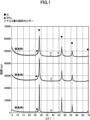
- FIG. 1 is an X-ray diffraction pattern of solids obtained in Examples 1 to 3.
- FIG. 1 is an X-ray diffraction pattern of solids obtained in Comparative Examples 1 to 3.
- FIG. 1 is a field emission scanning electron microscope observation photograph of the solid obtained in Example 1.
- Aluminosilicate is a salt formed by substituting a portion of Si in silicate with Al, and xM I 2 O.yAl 2 O 3.zSiO 2.nH 2 O (however, the metal is M II in some cases). , n may be 0).
- Aluminosilicates are abundant in nature as minerals such as micas, feldspars, zeolites, and clays. Among them, halloysite, which is a clay mineral, is characterized by being non-toxic and highly safe.
- the raw material aluminosilicate used in the present invention is not particularly limited, but halloysite, which has a small primary particle size in its natural state and a high specific surface area, is preferable. Due to the high specific surface area, reduction treatment can be performed effectively.
- Aluminosilicates have various structures such as chain, layer, network, and cylinder.
- the average particle size of the aluminosilicate powder is not particularly limited, but is preferably 1 to 20 ⁇ m, more preferably 2 to 5 ⁇ m, from the viewpoints of ease of reduction treatment and cost.
- the average particle size of the aluminosilicate is the particle size of the agglomerated particles, and a laser diffraction particle size distribution analyzer (e.g., , Mastersizer 3000).
- the raw material aluminosilicate of the present invention is an aluminosilicate having an Al 2 O 3 content of 3 to 40% by mass.
- an aluminosilicate containing Al 2 O 3 in such an amount, the efficiency of subsequent reduction can be increased and residual SiO 2 can be reduced. Then, oxidation of Si in the subsequent acid treatment step (b) can be prevented.
- the alumina content is preferably 5-40% by mass, more preferably 6-39% by mass, even more preferably 6-20% by mass.
- the content of Al 2 O 3 originally contained in halloysite is said to be about 35 to 40% by mass, regardless of the place of production of halloysite. Therefore, when halloysite is used as the raw material aluminosilicate, it can be used as it is, or it can be used after adjusting the Al 2 O 3 content within the above preferred range by appropriate means.
- Methods for adjusting the Al 2 O 3 content in the aluminosilicate include, for example, dealumination treatment, specifically hot sulfuric acid treatment.
- the amount of Al 2 O 3 can be controlled by adjusting the concentration of sulfuric acid, the mass ratio of sulfuric acid and aluminosilicate, the reaction temperature, the reaction time, and the like. For example, by treating 100 g of halloysite with 1200 g of 25% by weight sulfuric acid at 90° C. for 4 hours, halloysite with an Al 2 O 3 content of 18% can be obtained. Under the same conditions, the Al 2 O 3 content can be reduced to 15% when the treatment time is 5 hours, 6% when the treatment time is 7 hours, and 2% when the treatment time is 14 hours.
- Example 1 of Chinese Patent Publication No. 105905908 when 500 g of sulfuric acid having a concentration of 2 mol/L (17.2% by mass) was used to treat 5 g of halloysite at 100°C for 10 hours, Al 2 The O3 content was 0%.
- the dealumination treatment can be performed not only by hot sulfuric acid treatment but also by sulfuric acid treatment, hydrochloric acid treatment, hot hydrochloric acid treatment, nitric acid treatment, and hot nitric acid treatment.
- the reduction treatment can use magnesium as a reducing agent.
- the reducing agent is generally SiO 2 except for Al 2 O 3 in the raw material aluminosilicate
- the ratio of the number of aluminum atoms contained in the aluminosilicate to the number of magnesium atoms used as a reducing agent in the reduction treatment step is preferably 1:3.5 to 1:65, preferably 1:3.7 to 1. :45 is more preferred, and 1:3.7 to 1:30 is even more preferred.
- Alkali metal chlorides and alkaline earth metal chlorides act as endothermic agents. That is, since the reaction between SiO 2 in aluminosilicate and a reducing agent such as Mg is an exothermic reaction, Si obtained after reduction melts and agglomerates due to the heat of reaction.
- a reducing agent such as Mg
- Alkali metal chlorides include NaCl, KCl and the like. NaCl is preferred from the standpoint of availability and cost.
- Alkaline earth metal chlorides include CaCl 2 and MgCl 2 . CaCl2 is preferred because of its availability and cost.
- alkali metal chlorides are preferable from the viewpoint of availability and cost, and NaCl is particularly preferable.
- a sufficient amount of the endothermic agent so that it does not reach the melting point of silicon due to the heat of reaction. It is preferable to use
- the upper limit is preferably 12 or less in terms of mass ratio, because an increase in the amount makes it difficult for the reduction reaction to proceed.
- magnesium powder or aluminum powder with a molar ratio of 1 to 3 and NaCl with a mass ratio of 8 to 12 with respect to the aluminosilicate are used with respect to SiO 2 present in the raw material aluminosilicate, the effect of the reduction treatment and the cost will be reduced. is preferred.
- the reduction treatment can be performed by heating the aluminosilicate in which a specific amount of alumina remains in the presence of the reducing agent and the endothermic agent in an argon gas or nitrogen gas atmosphere.
- Reduction conditions can be appropriately set by those skilled in the art.
- the heating is carried out in a temperature range of, for example, 500 to 1000°C, preferably 500 to 800°C.
- the heating time is, for example, 1 to 24 hours, preferably 2 to 6 hours. Heating in an argon gas atmosphere at 500 to 800° C. for a heating time of 6 hours or less, for example, about 3 hours is preferable from the viewpoint of reduction treatment effect and cost.
- the present invention can be regarded as a method for extracting silicon by reducing an aluminosilicate mineral, so it can also be called a method for producing refined or smelted nano-silicon.
- it is typically preferred to wash with water by a conventional method to remove the endothermic agent.
- the washing water may be replaced with ethanol, and then heated to drive off the ethanol. Thereby, water can be removed more sufficiently.
- the acid used in this step is not particularly limited as long as it can achieve the above purpose, and for example, at least one acid selected from the group consisting of hydrochloric acid, sulfuric acid and nitric acid can be used. Among these, hydrochloric acid is preferable because it is relatively safe and the neutralized salt can be easily removed by washing with water.
- the acid concentration is preferably 0.3 to 8 mol/liter, more preferably 0.5 to 2.0 mol/liter, from the viewpoint of efficacy and safety.
- the amount of acid is not particularly limited, and it is preferable to use an amount capable of sufficiently dissolving by-products such as alumina and magnesia in the reduction step.
- the nanosilicon of the present invention can be suitably used as a negative electrode material for a lithium ion battery as a negative electrode active material, and can be suitably used for a lithium ion battery containing the negative electrode material.
- a lithium-ion battery has a configuration in which a secondary battery separator and an electrolyte are interposed between a positive electrode in which a positive electrode active material is laminated on a positive electrode current collector and a negative electrode in which a negative electrode active material layer is laminated on a negative electrode current collector. ing.
- the negative electrode for a lithium ion battery of the present invention preferably comprises a negative electrode active material layer containing a negative electrode active material, an electrolytic solution containing an electrolyte and a solvent, and a negative electrode current collector.
- the negative electrode active material layer can be made of only the negative electrode active material of the present invention, or can be made of a combination of the negative electrode active material of the present invention and a known negative electrode active material. , conductive materials, and electrolytes.
- Known negative electrode active materials that can be used in combination with the negative electrode active material of the present invention include carbon-based materials such as graphite and hard carbon soft carbon.
- the ratio of the negative electrode active material of the present invention is too low.
- the ratio is too high, repeated charging and discharging causes a decrease in the capacity of the negative electrode (decrease in cycle characteristics).
- the negative electrode active material of the present invention is carbon-coated using sucrose or the like as a raw material, the capacity of the negative electrode active material of the present invention can be efficiently obtained.
- the mass ratio represents the ratio between the total mass of the net mass of the negative electrode active material of the present invention and the mass of the carbon coat, and the mass of the known negative electrode active material.
- binders include known solvent-drying binders for lithium ion batteries such as carboxymethyl cellulose, styrene-butadiene rubber latex, starch, polyvinylidene fluoride, polyvinyl alcohol, polyvinylpyrrolidone, tetrafluoroethylene, polyethylene and polypropylene. can give.
- a binder When a binder is used, it is preferably used in an amount of 1/100 to 1/5 of the total amount of the negative electrode active material.
- conductive materials include acetylene black, graphite, ketjen black, and carbon black. When the conductive material is used, it is preferably used in an amount of 1/100 to 1/3 of the total amount of the negative electrode active material.
- electrolytes examples include lithium salts of inorganic anions such as LiPF 6 , LiBF 4 , LiSbF 6 , LiAsF 6 , LiClO 4 and LiN(FSO 2 ) 2 , LiN(CF 3 SO 2 ) 2 , LiN(C 2 F 5 Lithium salts of organic anions such as SO2 ) 2 and LiC( CF3SO2 ) 3 .
- inorganic anions such as LiPF 6 , LiBF 4 , LiSbF 6 , LiAsF 6 , LiClO 4 and LiN(FSO 2 ) 2 , LiN(CF 3 SO 2 ) 2 , LiN(C 2 F 5 Lithium salts of organic anions such as SO2 ) 2 and LiC( CF3SO2 ) 3 .
- Solvents include propylene carbonate, ethylene carbonate, 1,2-dimethoxyethane, ⁇ -butyrolactone, tetrahydrofuran, 2-methyltetrahydrofuran, 1,3-dioxolane, sulfolane, acetonitrile, diethyl carbonate, dimethyl carbonate, methylethyl carbonate, dipropyl Carbonate etc. are mentioned.
- the solvent may be used alone or in combination of two or more.
- Additives to solvents include vinylene carbonate, fluorovinylene carbonate, methyl vinylene carbonate, fluoromethyl vinylene carbonate, ethyl vinylene carbonate, propyl vinylene carbonate, butyl vinylene carbonate, dimethyl vinylene carbonate, diethyl vinylene carbonate, dipropyl vinylene carbonate, and vinylene acetate. , vinylene butyrate, vinylene hexanate, vinylene crotonate, catechol carbonate, propane sultone, butane sultone and the like. Additives may be used alone or in combination of two or more.
- the nanosilicon obtained by the production method of the present invention can be used for various purposes, and is preferably used as a negative electrode material for lithium ion batteries.
- the nano-silicon obtained by the production method of the present invention usually has a small primary particle diameter of about 10 to 15 nm, and is uniform in particle size as shown in FIG.
- the nanosilicon obtained by the production method of the present invention also does not have amorphous SiO 2 halos confirmed by diffraction X-ray analysis, nor does it have spinel peaks confirmed by diffraction X-ray analysis. That is, according to the present invention, highly pure nanosilicon can be obtained.
- Si When Si is used as a negative electrode material for lithium-ion batteries, the problem is that it pulverizes due to volumetric changes caused by the intercalation and deintercalation of lithium ions, resulting in a decrease in capacity. However, if the silicon particles are small, pulverization is less likely to proceed due to volume change, and a negative electrode for a lithium ion battery with excellent cycle characteristics can be obtained. When the particle size is uniform, the voids between particles become large, which is advantageous in terms of cycle characteristics. In addition, in this specification, “%” represents “% by mass” unless otherwise specified.
- Pretreatment 1-thermal sulfuric acid treatment 1200 g of a 25% sulfuric acid aqueous solution was heated to 90° C., and 100 g of dry-pulverized halloysite powder (trade name: DRAGONITE-HP, manufactured by Applied Minerals, average particle size: 12 ⁇ m) was added while stirring. A lid was placed so that the concentration of sulfuric acid would not change significantly due to evaporation of water, and the reaction was allowed to proceed for 5 hours while maintaining the temperature at 90° C. while stirring. After that, the remaining solid matter was collected on filter paper by suction filtration.
- dry-pulverized halloysite powder trade name: DRAGONITE-HP, manufactured by Applied Minerals, average particle size: 12 ⁇ m
- Distilled water was further added to the collected solid matter, suction filtration was continued, and the solid matter was washed with water until the ionic conductivity of the filtrate became 30 ⁇ S/cm or less. This removed sulfuric acid and water-soluble reaction products from the solid. After drying the solid at 120° C. for 24 hours, it was pulverized with a pneumatic pulverizer (SJ-100CB manufactured by Nisshin Engineering Co., Ltd.) to obtain a white aluminosilicate powder having an average particle size of about 3 ⁇ m.
- a pneumatic pulverizer SJ-100CB manufactured by Nisshin Engineering Co., Ltd.
- Pretreatment 2-thermal sulfuric acid treatment> A white powder of aluminosilicate was obtained by the same treatment as pretreatment 1 except that the reaction time was 14 hours. This aluminosilicate was measured in the same manner as in pretreatment 1 and confirmed to contain 2% Al 2 O 3 .
- Pretreatment 3 Thermal sulfuric acid treatment> A white powder of aluminosilicate was obtained by the same treatment as pretreatment 1 except that the reaction time was 7 hours. This aluminosilicate was measured in the same manner as in pretreatment 1 and confirmed to contain 6% Al 2 O 3 .
- Example 1 (Mixed with NaCl and dried) 4.88 g of the aluminosilicate prepared in pretreatment 1 was mixed with 41.48 g of NaCl and 137 mL of distilled water, and the mixture was stirred at room temperature for 1 hour. After that, the solvent was evaporated under reduced pressure using a rotary evaporator, and further dried at 120° C. for 12 hours.
- the starting material is the aluminosilicate obtained in pretreatment 3
- the amount of NaCl is 46.07 g
- the amount of distilled water is 148 mL
- the amount of powder mixed with NaCl and dried and pulverized in the mixing step with Mg. is 8.85 g
- the ratio of the number of aluminum atoms contained in the aluminosilicate to the number of magnesium atoms used as a reducing agent in the reduction treatment step is 1: 29.7).
- a brown solid was obtained by the same operation as in Example 1. When the obtained brown solid matter was analyzed by diffraction X-rays, a clear silicon peak was observed (Fig. 1).
- Example 3 The starting material is the aluminosilicate obtained in pretreatment 4, NaCl is 29.96 g, distilled water is 103 mL, and in the mixing step with Mg, the amount of powder mixed with NaCl and dried and pulverized is 9.30 g, and the amount of Mg powder is 0.94 g [SiO 2 : Mg ⁇ 1:2.90 (molar ratio)] (calculated as SiO 2 except for Al 2 O 3 ) (at this time, The ratio of the number of aluminum atoms contained in the aluminosilicate to the number of magnesium atoms used as a reducing agent in the reduction treatment step is 1:3.9), the amount of 1M hydrochloric acid solution used in the HCl treatment step A brown solid was obtained in the same manner as in Example 1, except that the was 160 mL.
- Example 4 10.4 g of the brown solid matter (nano-silicon) obtained in Example 1, 5.2 g of sucrose, 59.1 g of methanol, and 25.3 g of distilled water were crushed in a mortar and suspended. created a liquid. The suspension was dried at an inlet temperature of 100° C. using a micro-mist spray dryer (manufactured by GF Co., Ltd.) to obtain a powder. After the powder was dried under reduced pressure at 60° C. for 2 hours, it was heated at 800° C. for 2 hours in an Ar atmosphere to carbon-coat a brown solid (nano-silicon).
- a micro-mist spray dryer manufactured by GF Co., Ltd.
- the starting material is the aluminosilicate obtained in pretreatment 2, 48.06 g of NaCl, 154 mL of distilled water, and in the mixing step with Mg, the amount of powder mixed with NaCl, dried and pulverized is 8 .81 g (At this time, after mixing with Mg, the ratio of the number of aluminum atoms contained in the aluminosilicate to the number of magnesium atoms used as a reducing agent in the reduction treatment step is 1:93.0) A brown solid was obtained in the same manner as in Example 1, except that When the obtained brown solid matter was analyzed by diffraction X-rays, a clear silicon peak was observed (Fig. 2).
- Example 4 A basic evaluation cell (half cell) was prepared under the same conditions as in Example 4 except that the silicon used for the working electrode was commercially available carbon-coated 100-nanometer silicon. Polar properties were measured. Tables 3 and 4 show unipolar characteristics.
- Example 1 When the ratio of the number of atoms of magnesium was adjusted to 1:29.7, 1:10.7, and 1:3.9 and was subjected to reduction treatment (Examples 1 to 3), amorphous No SiO 2 halo or spinel (MgAl 2 O 4 ) peak was observed (Fig. 1). Furthermore, the primary particle size of the silicon of Example 1 was 10 to 15 nm, which was smaller than that of Comparative Example 2. When trying to obtain high-purity silicon, in Comparative Examples 1 and 2, an amorphous SiO 2 halo is present to the extent that it can be confirmed by diffraction X-ray analysis. A step of removing amorphous SiO 2 with hydrofluoric acid is required.
- the ratio of the number of aluminum atoms contained in the aluminosilicate to the number of magnesium atoms used as a reducing agent in the reduction treatment step was 1:3.0, and the amount of aluminum was magnesium If the amount becomes excessive with respect to the amount of , spinel (MgAl 2 O 4 ) that cannot be removed by acid treatment is formed.
- spinel MgAl 2 O 4
- an appropriate amount of alumina is left, and the ratio of the number of aluminum atoms contained in the aluminosilicate and the number of magnesium atoms used as a reducing agent in the reduction treatment step is within an appropriate range.
- High-purity silicon having no amorphous SiO 2 halo and no spinel peak was obtained by diffraction X-ray analysis.
- the mass % of oxygen is calculated from the atomic number concentrations of O, Al and Si in Example 1, it is 13.49 mass %.
- the density of silicon is 2.33
- the density of SiO 2 is 2.3
- the primary particle diameter of nanosilicon is 10 nm
- the thickness of the SiO 2 film present on the primary nanosilicon particles of Example 1 is about 0.5 nm.
- this SiO 2 thickness does not hinder the entry and exit of lithium ions and electrons into and out of the nanosilicon.
- the present invention can be used as a negative electrode material for lithium ion batteries, for example, without performing the step of removing amorphous SiO 2 with hydrofluoric acid, which is very dangerous and costly.
- High-purity nanosilicon is obtained.
- a basic evaluation cell (half cell) was actually prepared, and a charge-discharge cycle test was performed.
- the silicon obtained by the present invention was carbon-coated and the working electrode (negative electrode) was blended into a lithium ion battery (Example 4).
- Example 4 Compared to the lithium ion battery (Comparative Example 4) in which the working electrode was mixed with commercially available 100-nanometer silicon after carbon coating, the amount of silicon carbon coating was larger in Example 4, and the initial capacity was smaller than that of Comparative Example 4, but the capacity retention rate was excellent in the cycle test. The battery capacity also increased in the example after the 5th cycle.
- silicon is used as a negative electrode material for a lithium ion battery, there is a problem that it pulverizes due to a volume change due to the intercalation and deintercalation of lithium ions, resulting in a decrease in capacity.
- the size of the silicon particles obtained in the present invention is as small as 10 to 15 nanometers, and it is thought that pulverization is unlikely to progress due to volume change, and that the capacity retention ratio was excellent in the cycle test.
Landscapes
- Chemical & Material Sciences (AREA)
- Organic Chemistry (AREA)
- Engineering & Computer Science (AREA)
- Inorganic Chemistry (AREA)
- Chemical Kinetics & Catalysis (AREA)
- Electrochemistry (AREA)
- General Chemical & Material Sciences (AREA)
- Materials Engineering (AREA)
- Manufacturing & Machinery (AREA)
- Silicates, Zeolites, And Molecular Sieves (AREA)
- Silicon Compounds (AREA)
- Battery Electrode And Active Subsutance (AREA)
Priority Applications (4)
| Application Number | Priority Date | Filing Date | Title |
|---|---|---|---|
| KR1020237011251A KR20230058513A (ko) | 2021-09-21 | 2022-09-21 | 나노 실리콘의 제조 방법과, 리튬 이온 전지용 음극 활물질, 리튬 이온 전지용 음극, 및 리튬 이온 전지 |
| JP2023516581A JPWO2023048167A1 (https=) | 2021-09-21 | 2022-09-21 | |
| US18/247,305 US20230406715A1 (en) | 2021-09-21 | 2022-09-21 | Method for producing nano-silicon, negative electrode active material for lithium-ion batteries, negative electrode for lithium-ion batteries, and lithium-ion battery |
| CN202280006654.8A CN116508173B (zh) | 2021-09-21 | 2022-09-21 | 纳米硅的制造方法、锂离子电池用负极活性物质、锂离子电池用负极及锂离子电池 |
Applications Claiming Priority (2)
| Application Number | Priority Date | Filing Date | Title |
|---|---|---|---|
| JP2021-152868 | 2021-09-21 | ||
| JP2021152868A JP7191410B1 (ja) | 2021-09-21 | 2021-09-21 | ナノシリコンの製造方法 |
Publications (1)
| Publication Number | Publication Date |
|---|---|
| WO2023048167A1 true WO2023048167A1 (ja) | 2023-03-30 |
Family
ID=84546030
Family Applications (1)
| Application Number | Title | Priority Date | Filing Date |
|---|---|---|---|
| PCT/JP2022/035121 Ceased WO2023048167A1 (ja) | 2021-09-21 | 2022-09-21 | ナノシリコンの製造方法と、リチウムイオン電池用負極活物質、リチウムイオン電池用負極、及びリチウムイオン電池 |
Country Status (5)
| Country | Link |
|---|---|
| US (1) | US20230406715A1 (https=) |
| JP (2) | JP7191410B1 (https=) |
| KR (1) | KR20230058513A (https=) |
| CN (1) | CN116508173B (https=) |
| WO (1) | WO2023048167A1 (https=) |
Families Citing this family (3)
| Publication number | Priority date | Publication date | Assignee | Title |
|---|---|---|---|---|
| US20240018006A1 (en) * | 2022-07-13 | 2024-01-18 | Uchicago Argonne, Llc | Method For Producing Porous Nanocrystalline Silicon |
| JP7656761B1 (ja) * | 2024-08-20 | 2025-04-03 | Jfeミネラル株式会社 | 粉末および粉末の製造方法 |
| JP7656762B1 (ja) * | 2024-08-20 | 2025-04-03 | Jfeミネラル株式会社 | アルミノシリケート顆粒、粉末 |
Citations (4)
| Publication number | Priority date | Publication date | Assignee | Title |
|---|---|---|---|---|
| JP2007242630A (ja) * | 2007-05-14 | 2007-09-20 | Mitsubishi Chemicals Corp | 非水系二次電池 |
| WO2014102219A1 (en) * | 2012-12-24 | 2014-07-03 | Solvay Sa | Silicon nanosheet and preparing method of the same |
| JP2016506029A (ja) * | 2013-10-31 | 2016-02-25 | エルジー・ケム・リミテッド | リチウム二次電池用負極活物質及びその製造方法 |
| CN105905908A (zh) * | 2016-04-20 | 2016-08-31 | 中南大学 | 一种基于埃洛石原料制备纳米硅的方法 |
Family Cites Families (1)
| Publication number | Priority date | Publication date | Assignee | Title |
|---|---|---|---|---|
| DE112015002524T5 (de) * | 2014-05-29 | 2017-02-23 | Kabushiki Kaisha Toyota Jidoshokki | Nano-Silizium-Material, Verfahren zur Herstellung desselben und Negatvelektrode einer Sekundärbatterie |
-
2021
- 2021-09-21 JP JP2021152868A patent/JP7191410B1/ja active Active
-
2022
- 2022-09-21 WO PCT/JP2022/035121 patent/WO2023048167A1/ja not_active Ceased
- 2022-09-21 JP JP2023516581A patent/JPWO2023048167A1/ja active Pending
- 2022-09-21 KR KR1020237011251A patent/KR20230058513A/ko active Pending
- 2022-09-21 US US18/247,305 patent/US20230406715A1/en active Pending
- 2022-09-21 CN CN202280006654.8A patent/CN116508173B/zh active Active
Patent Citations (4)
| Publication number | Priority date | Publication date | Assignee | Title |
|---|---|---|---|---|
| JP2007242630A (ja) * | 2007-05-14 | 2007-09-20 | Mitsubishi Chemicals Corp | 非水系二次電池 |
| WO2014102219A1 (en) * | 2012-12-24 | 2014-07-03 | Solvay Sa | Silicon nanosheet and preparing method of the same |
| JP2016506029A (ja) * | 2013-10-31 | 2016-02-25 | エルジー・ケム・リミテッド | リチウム二次電池用負極活物質及びその製造方法 |
| CN105905908A (zh) * | 2016-04-20 | 2016-08-31 | 中南大学 | 一种基于埃洛石原料制备纳米硅的方法 |
Non-Patent Citations (1)
| Title |
|---|
| ZHOU XIANGYANG; WU LILI; YANG JUAN; TANG JINGJING; XI LIHUA; WANG BIAO: "Synthesis of nano-sized silicon from natural halloysite clay and its high performance as anode for lithium-ion batteries", JOURNAL OF POWER SOURCES, ELSEVIER, AMSTERDAM, NL, vol. 324, 21 May 2016 (2016-05-21), AMSTERDAM, NL, pages 33 - 40, XP029624592, ISSN: 0378-7753, DOI: 10.1016/j.jpowsour.2016.05.058 * |
Also Published As
| Publication number | Publication date |
|---|---|
| CN116508173B (zh) | 2024-12-24 |
| JP7191410B1 (ja) | 2022-12-19 |
| CN116508173A (zh) | 2023-07-28 |
| JPWO2023048167A1 (https=) | 2023-03-30 |
| US20230406715A1 (en) | 2023-12-21 |
| JP2023044813A (ja) | 2023-04-03 |
| KR20230058513A (ko) | 2023-05-03 |
Similar Documents
| Publication | Publication Date | Title |
|---|---|---|
| EP3158599B1 (en) | Porous silicon electrode and method | |
| JP7760605B2 (ja) | 負極材料、その調製方法およびリチウムイオン電池 | |
| WO2023048167A1 (ja) | ナノシリコンの製造方法と、リチウムイオン電池用負極活物質、リチウムイオン電池用負極、及びリチウムイオン電池 | |
| CN107735888B (zh) | 锂二次电池用负极活性材料及其制备方法 | |
| CN119943920A (zh) | 碳涂覆的硅氧化物/石墨复合颗粒及其制备方法和应用 | |
| KR101751787B1 (ko) | 리튬이차전지용 실리콘 복합재 음극활물질, 이의 제조방법 및 이를 포함하는 리튬이차전지 | |
| JP2023509810A (ja) | 負極材料及びその製造方法、リチウムイオン電池 | |
| WO2022199389A1 (zh) | 硅氧复合负极材料及其制备方法、锂离子电池 | |
| CN107710464B (zh) | 多孔硅颗粒及生产硅颗粒的方法 | |
| CA2752844A1 (en) | Method for preparing a particulate of si or siox-based anode material, and material thus obtained | |
| JP2010001214A (ja) | 結晶状のナノメーターLiFePO4 | |
| WO2017214882A1 (en) | Porous silicon particles and a method for producing silicon particles | |
| CN107636867A (zh) | 锂二次电池用负极活性材料及其制备方法 | |
| KR101604003B1 (ko) | 리튬이차전지용 실리콘 복합재 음극활물질, 이의 제조방법 및 이를 포함하는 리튬이차전지 | |
| JP5804427B2 (ja) | 二次電池用正極材活物質の製造方法 | |
| JP2013206869A (ja) | リチウムチタン複合酸化物、それを用いた電池用電極およびリチウムイオン二次電池 | |
| JP3894615B2 (ja) | チタン酸リチウムおよびその製造方法ならびにそれを用いてなるリチウム電池 | |
| JP5728515B2 (ja) | 二次電池用正極材料の製造方法 | |
| TW202115952A (zh) | 塗覆有熱解製造的含鋯氧化物之混合鋰過渡金屬氧化物 | |
| CN117174849A (zh) | 掺杂有锂的硅基负极活性物质、其制备方法、其后处理方法、包含其的负极和二次电池 | |
| CN116864653A (zh) | 预镁硅氧负极材料及其制备方法、及二次电池 | |
| CN111936419B (zh) | 硅锂离子电极材料 | |
| TW202125879A (zh) | 含有熱解生產的含鋯氧化物之混合鋰過渡金屬氧化物 | |
| CN115719799A (zh) | 一种非晶电池材料及其制备方法和应用 | |
| JP2025040217A (ja) | 炭素コートされた無機物粉体の製造方法と、炭素コートされたシリコン又はSiO、及びそれを負極材活物質として含むリチウムイオン二次電池 |
Legal Events
| Date | Code | Title | Description |
|---|---|---|---|
| WWE | Wipo information: entry into national phase |
Ref document number: 2023516581 Country of ref document: JP |
|
| WWE | Wipo information: entry into national phase |
Ref document number: 202280006654.8 Country of ref document: CN |
|
| ENP | Entry into the national phase |
Ref document number: 20237011251 Country of ref document: KR Kind code of ref document: A |
|
| 121 | Ep: the epo has been informed by wipo that ep was designated in this application |
Ref document number: 22872919 Country of ref document: EP Kind code of ref document: A1 |
|
| NENP | Non-entry into the national phase |
Ref country code: DE |
|
| 122 | Ep: pct application non-entry in european phase |
Ref document number: 22872919 Country of ref document: EP Kind code of ref document: A1 |