WO2023047797A1 - 医療装置 - Google Patents
医療装置 Download PDFInfo
- Publication number
- WO2023047797A1 WO2023047797A1 PCT/JP2022/029160 JP2022029160W WO2023047797A1 WO 2023047797 A1 WO2023047797 A1 WO 2023047797A1 JP 2022029160 W JP2022029160 W JP 2022029160W WO 2023047797 A1 WO2023047797 A1 WO 2023047797A1
- Authority
- WO
- WIPO (PCT)
- Prior art keywords
- gear
- unit
- catheter
- medical device
- wire
- Prior art date
Links
- 230000007246 mechanism Effects 0.000 claims abstract description 114
- 238000005452 bending Methods 0.000 claims abstract description 63
- 230000033001 locomotion Effects 0.000 claims abstract description 60
- 230000009467 reduction Effects 0.000 claims description 31
- 230000007704 transition Effects 0.000 claims description 4
- 238000010586 diagram Methods 0.000 description 29
- 238000003780 insertion Methods 0.000 description 24
- 230000037431 insertion Effects 0.000 description 24
- 230000008878 coupling Effects 0.000 description 11
- 238000010168 coupling process Methods 0.000 description 11
- 238000005859 coupling reaction Methods 0.000 description 11
- 238000006243 chemical reaction Methods 0.000 description 8
- 230000006870 function Effects 0.000 description 6
- 230000005540 biological transmission Effects 0.000 description 5
- 239000003638 chemical reducing agent Substances 0.000 description 5
- 238000000034 method Methods 0.000 description 5
- 230000004048 modification Effects 0.000 description 5
- 238000012986 modification Methods 0.000 description 5
- 230000002093 peripheral effect Effects 0.000 description 5
- 230000001105 regulatory effect Effects 0.000 description 5
- 230000009471 action Effects 0.000 description 4
- 230000008859 change Effects 0.000 description 4
- 239000000463 material Substances 0.000 description 4
- 239000002184 metal Substances 0.000 description 4
- 230000008569 process Effects 0.000 description 4
- 238000013459 approach Methods 0.000 description 3
- 239000011347 resin Substances 0.000 description 3
- 229920005989 resin Polymers 0.000 description 3
- 238000011144 upstream manufacturing Methods 0.000 description 3
- 230000008901 benefit Effects 0.000 description 2
- 238000002679 ablation Methods 0.000 description 1
- 230000002238 attenuated effect Effects 0.000 description 1
- 210000000621 bronchi Anatomy 0.000 description 1
- 230000006835 compression Effects 0.000 description 1
- 238000007906 compression Methods 0.000 description 1
- 230000001276 controlling effect Effects 0.000 description 1
- 239000000428 dust Substances 0.000 description 1
- 239000012530 fluid Substances 0.000 description 1
- 230000002452 interceptive effect Effects 0.000 description 1
- 230000009545 invasion Effects 0.000 description 1
- 210000004072 lung Anatomy 0.000 description 1
- 210000000214 mouth Anatomy 0.000 description 1
- 210000003928 nasal cavity Anatomy 0.000 description 1
- 238000012545 processing Methods 0.000 description 1
- 230000000717 retained effect Effects 0.000 description 1
Images


Classifications
-
- A—HUMAN NECESSITIES
- A61—MEDICAL OR VETERINARY SCIENCE; HYGIENE
- A61B—DIAGNOSIS; SURGERY; IDENTIFICATION
- A61B34/00—Computer-aided surgery; Manipulators or robots specially adapted for use in surgery
- A61B34/25—User interfaces for surgical systems
-
- A—HUMAN NECESSITIES
- A61—MEDICAL OR VETERINARY SCIENCE; HYGIENE
- A61B—DIAGNOSIS; SURGERY; IDENTIFICATION
- A61B1/00—Instruments for performing medical examinations of the interior of cavities or tubes of the body by visual or photographical inspection, e.g. endoscopes; Illuminating arrangements therefor
- A61B1/00002—Operational features of endoscopes
- A61B1/00004—Operational features of endoscopes characterised by electronic signal processing
- A61B1/00006—Operational features of endoscopes characterised by electronic signal processing of control signals
-
- A—HUMAN NECESSITIES
- A61—MEDICAL OR VETERINARY SCIENCE; HYGIENE
- A61B—DIAGNOSIS; SURGERY; IDENTIFICATION
- A61B1/00—Instruments for performing medical examinations of the interior of cavities or tubes of the body by visual or photographical inspection, e.g. endoscopes; Illuminating arrangements therefor
- A61B1/00002—Operational features of endoscopes
- A61B1/00039—Operational features of endoscopes provided with input arrangements for the user
- A61B1/00042—Operational features of endoscopes provided with input arrangements for the user for mechanical operation
-
- A—HUMAN NECESSITIES
- A61—MEDICAL OR VETERINARY SCIENCE; HYGIENE
- A61B—DIAGNOSIS; SURGERY; IDENTIFICATION
- A61B1/00—Instruments for performing medical examinations of the interior of cavities or tubes of the body by visual or photographical inspection, e.g. endoscopes; Illuminating arrangements therefor
- A61B1/00147—Holding or positioning arrangements
- A61B1/0016—Holding or positioning arrangements using motor drive units
-
- A—HUMAN NECESSITIES
- A61—MEDICAL OR VETERINARY SCIENCE; HYGIENE
- A61B—DIAGNOSIS; SURGERY; IDENTIFICATION
- A61B1/00—Instruments for performing medical examinations of the interior of cavities or tubes of the body by visual or photographical inspection, e.g. endoscopes; Illuminating arrangements therefor
- A61B1/005—Flexible endoscopes
- A61B1/0051—Flexible endoscopes with controlled bending of insertion part
- A61B1/0052—Constructional details of control elements, e.g. handles
-
- A—HUMAN NECESSITIES
- A61—MEDICAL OR VETERINARY SCIENCE; HYGIENE
- A61B—DIAGNOSIS; SURGERY; IDENTIFICATION
- A61B1/00—Instruments for performing medical examinations of the interior of cavities or tubes of the body by visual or photographical inspection, e.g. endoscopes; Illuminating arrangements therefor
- A61B1/005—Flexible endoscopes
- A61B1/0051—Flexible endoscopes with controlled bending of insertion part
- A61B1/0057—Constructional details of force transmission elements, e.g. control wires
-
- A—HUMAN NECESSITIES
- A61—MEDICAL OR VETERINARY SCIENCE; HYGIENE
- A61B—DIAGNOSIS; SURGERY; IDENTIFICATION
- A61B1/00—Instruments for performing medical examinations of the interior of cavities or tubes of the body by visual or photographical inspection, e.g. endoscopes; Illuminating arrangements therefor
- A61B1/005—Flexible endoscopes
- A61B1/008—Articulations
-
- A—HUMAN NECESSITIES
- A61—MEDICAL OR VETERINARY SCIENCE; HYGIENE
- A61B—DIAGNOSIS; SURGERY; IDENTIFICATION
- A61B1/00—Instruments for performing medical examinations of the interior of cavities or tubes of the body by visual or photographical inspection, e.g. endoscopes; Illuminating arrangements therefor
- A61B1/267—Instruments for performing medical examinations of the interior of cavities or tubes of the body by visual or photographical inspection, e.g. endoscopes; Illuminating arrangements therefor for the respiratory tract, e.g. laryngoscopes, bronchoscopes
- A61B1/2676—Bronchoscopes
-
- A—HUMAN NECESSITIES
- A61—MEDICAL OR VETERINARY SCIENCE; HYGIENE
- A61B—DIAGNOSIS; SURGERY; IDENTIFICATION
- A61B34/00—Computer-aided surgery; Manipulators or robots specially adapted for use in surgery
- A61B34/30—Surgical robots
-
- A—HUMAN NECESSITIES
- A61—MEDICAL OR VETERINARY SCIENCE; HYGIENE
- A61B—DIAGNOSIS; SURGERY; IDENTIFICATION
- A61B34/00—Computer-aided surgery; Manipulators or robots specially adapted for use in surgery
- A61B34/30—Surgical robots
- A61B34/32—Surgical robots operating autonomously
-
- A—HUMAN NECESSITIES
- A61—MEDICAL OR VETERINARY SCIENCE; HYGIENE
- A61M—DEVICES FOR INTRODUCING MEDIA INTO, OR ONTO, THE BODY; DEVICES FOR TRANSDUCING BODY MEDIA OR FOR TAKING MEDIA FROM THE BODY; DEVICES FOR PRODUCING OR ENDING SLEEP OR STUPOR
- A61M25/00—Catheters; Hollow probes
- A61M25/01—Introducing, guiding, advancing, emplacing or holding catheters
- A61M25/0105—Steering means as part of the catheter or advancing means; Markers for positioning
- A61M25/0116—Steering means as part of the catheter or advancing means; Markers for positioning self-propelled, e.g. autonomous robots
-
- A—HUMAN NECESSITIES
- A61—MEDICAL OR VETERINARY SCIENCE; HYGIENE
- A61B—DIAGNOSIS; SURGERY; IDENTIFICATION
- A61B34/00—Computer-aided surgery; Manipulators or robots specially adapted for use in surgery
- A61B34/25—User interfaces for surgical systems
- A61B2034/252—User interfaces for surgical systems indicating steps of a surgical procedure
-
- A—HUMAN NECESSITIES
- A61—MEDICAL OR VETERINARY SCIENCE; HYGIENE
- A61B—DIAGNOSIS; SURGERY; IDENTIFICATION
- A61B34/00—Computer-aided surgery; Manipulators or robots specially adapted for use in surgery
- A61B34/30—Surgical robots
- A61B2034/301—Surgical robots for introducing or steering flexible instruments inserted into the body, e.g. catheters or endoscopes
Definitions
- the present invention relates to a medical device having a bendable bending portion.
- Patent Literature 1 discloses a medical device that includes an operated portion having a deformable portion and an operating portion that deforms the deformable portion, the operated portion and the operating portion being detachable.
- the operated portion is provided with a wire for deforming the deformation portion, and the operated portion side magnet is fixed to the wire.
- a wire wound around a pulley is provided in the operating portion, and the operating portion-side magnet is fixed to the wire.
- a medical device includes a drive source, a base unit including a connecting portion connected to the drive source, and a bendable unit detachably attached to the base unit, the bendable device comprising: and a linear member configured to be connectable to the connecting portion and driven by the drive source via the connecting portion to bend the bending portion, and an operation portion. and a speed reduction mechanism including an output member driven by the force transmitted from the operating portion.
- the connecting portion can transition between a holding state in which the linear member is held while the bendable unit is attached to the base unit, and a release state in which the holding of the linear member is released. a holding portion; and a switching portion moved by the output member to switch the holding portion between the held state and the released state.
- the output member is configured to move by a second movement amount smaller than the first movement amount when the operation unit moves by a first movement amount.
- FIG. 1 is a perspective view showing a medical device and a support base; FIG. The whole perspective view which shows a catheter.
- FIG. 2 is an enlarged perspective view showing a catheter;
- FIG. 4 is a perspective view showing the catheter unit with the wire cover in the cover position;
- FIG. 4 is a perspective view showing the catheter unit with the wire cover in the exposed position;
- the side view which shows the internal structure of a base unit.
- the perspective view which shows a drive source, a connection part, and a drive wire.
- FIG. 1 is a perspective view showing a medical device and a support base
- FIG. 2 is an enlarged perspective view showing a catheter
- FIG. 4 is a perspective view showing the catheter unit with the wire cover in the cover position
- FIG. 4 is a perspective view showing the catheter unit with the
- FIG. 4 is an enlarged view showing a connecting part and a drive wire; The perspective view which shows a wire drive part, a coupling device, and a bending drive part.
- FIG. 4 is a cross-sectional view showing a state before the catheter unit is attached to the base unit;
- FIG. 4 is a cross-sectional view showing a state after the catheter unit is attached to the base unit;
- FIG. 3 is a perspective view showing a connecting portion of the base unit to the catheter unit;
- FIG. 3 is a perspective view showing a planetary gear mechanism built into the base unit;
- FIG. 3 is an exploded perspective view showing an operating portion and a planetary gear mechanism;
- FIG. 2 is an exploded perspective view showing a planetary gear mechanism;
- FIG. 4 is a cross-sectional view of the operation section and the base unit cut along the rotation axis of the operation section;
- FIG. 13 is a sectional view showing the 13A-13A section of FIG. 12;
- FIG. 4 is a cross-sectional view of the catheter unit and the base unit cut along the rotation axis of the operating section;
- Sectional drawing which cut
- FIG. 4 is a cross-sectional view showing a state in which the operating portion is at the removal position;
- FIG. 4 is a cross-sectional view showing a state in which the operation portion is at the release position;
- FIG. 4 is a cross-sectional view showing a state in which the operating portion is in a fixed position;
- 1 is a skeleton diagram showing a planetary type planetary gear mechanism according to a first embodiment;
- FIG. 4 is a skeleton diagram showing a solar-type planetary gear mechanism according to a modification of the first embodiment
- FIG. 8 is a skeleton diagram showing a star-shaped planetary gear mechanism according to another modification of the first embodiment
- FIG. 2 is an exploded perspective view showing a step gear mechanism;
- FIG. 1 is an overall view of a medical system 1A.
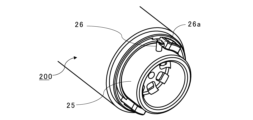
- FIG. 2 is a perspective view showing the medical device 1 and the support base 2.
- FIG. 1 is an overall view of a medical system 1A.
- FIG. 2 is a perspective view showing the medical device 1 and the support base 2.
- the medical system 1A includes a medical device 1, a support base 2 to which the medical device 1 is attached, and a controller (control device) 3 that controls the medical device 1.
- the medical system 1A includes a monitor 4 as a display device.
- the medical device 1 includes a catheter unit (bendable unit) 100 having a catheter 11 as a bendable body, and a base unit (driving unit, wearable unit) 200 .
- the catheter unit 100 is detachably attached to the base unit 200 .
- the user of the medical system 1A and the medical device 1 inserts the catheter 11 into the subject to observe the interior of the subject, collect various specimens from the interior of the subject, and treat the interior of the subject. etc. can be performed.
- the user can insert the catheter 11 into the subject patient. Specifically, by inserting the device into the bronchi through the patient's oral cavity or nasal cavity, operations such as observation, collection, and excision of lung tissue can be performed.
- the catheter 11 can be used as a guide (sheath) for guiding medical instruments for performing the above operations.
- medical instruments include endoscopes, forceps, ablation devices, and the like.
- the catheter 11 itself may have a function as the above-described medical device, and in that case, the catheter 11 is not limited to a cylindrical shape, and may be cylindrical, for example.
- control unit 3 includes an arithmetic device 3a and an input device 3b.
- the input device 3 b receives commands and inputs for operating the catheter 11 .
- the arithmetic unit 3a includes a storage for storing programs for controlling the catheter and various data, a random access memory, and a central processing unit for executing the programs.
- control unit 3 may include an output unit that outputs a signal for displaying an image on the monitor 4 .
- the medical device 1 is electrically connected to the control unit 3 via the support base 2 and the cable 5 connecting the base unit 200 of the medical device 1 and the support base 2. be done.
- the medical device 1 and the control unit 3 may be directly connected by a cable.
- the medical device 1 and the controller 3 may be wirelessly connected.
- the medical device 1 is detachably attached to the support base 2 via the base unit 200 . More specifically, in the medical device 1 , the attaching portion (connecting portion) 200 a of the base unit 200 is detachably attached to the moving stage (receiving portion) 2 a of the support base 2 .
- the connection between the medical device 1 and the controller 3 is maintained so that the medical device 1 can be controlled by the controller 3 even when the mounting portion 200a of the medical device 1 is removed from the moving stage 2a.
- the medical device 1 and the support base 2 are connected by the cable 5 even when the mounting portion 200a of the medical device 1 is removed from the moving stage 2a.
- the user manually moves the medical device 1 in a state in which the medical device 1 is removed from the support base 2 (a state in which the medical device 1 is removed from the moving stage 2a), and inserts the catheter 11 into the subject. be able to.
- the user can use the medical device 1 with the catheter 11 inserted into the target and the medical device 1 attached to the support base 2 .
- the medical apparatus 1 is moved by moving the movable stage 2a while the medical apparatus 1 is attached to the movable stage 2a. Then, an operation of moving the catheter 11 in the direction of inserting it into the object and an operation of moving the catheter 11 in the direction of pulling it out from the object are performed.
- the movement of the moving stage 2a is controlled by the controller 3.
- the mounting portion 200a of the base unit 200 has a release switch and a removal switch (not shown). With the mounting portion 200a attached to the moving stage 2a, the user can manually move the medical device 1 along the guide direction of the moving stage 2a while continuing to press the release switch. That is, the moving stage 2a has a guide structure that guides the movement of the medical device 1. As shown in FIG. When the user stops pressing the release switch, the medical device 1 is fixed to the moving stage 2a. On the other hand, when the detachment switch is pressed while the mounting portion 200a is attached to the moving stage 2a, the user can detach the medical device 1 from the moving stage 2a.
- one switch may have the function of the release switch and the function of the removal switch. Further, if the release switch is provided with a mechanism for switching the release switch between the pressed state and the non-pressed state, the user does not need to keep pressing the release switch when the medical device 1 is manually slid.
- the medical device 1 is fixed to the moving stage 2a and moved by the moving stage 2a driven by a motor (not shown). be.
- the medical device 1 includes a wire drive section (linear member drive section, line drive section, main body drive section) 300 for driving the catheter 11 .
- the medical device 1 is a robotic catheter device that drives the catheter 11 by means of a wire driving section 300 controlled by the control section 3 .
- the control unit 3 can control the wire driving unit 300 and bend the catheter 11 .
- the wire driving section 300 is built into the base unit 200 .
- the base unit 200 includes a base housing 200f that houses the wire driving section 300.
- the base unit 200 includes the wire driving section 300.
- the wire driving section 300 and the base unit 200 together can be called a catheter driving device (base device, main body).
- the end where the tip of the catheter 11 inserted into the object is arranged is called the distal end.
- the side opposite to the distal end with respect to the extending direction of the catheter 11 is called the proximal end.
- the catheter unit 100 has a proximal end cover 16 that covers the proximal end side of the catheter 11 .
- the proximal end cover 16 has a tool hole 16a. A medical instrument can be inserted into the catheter 11 through the tool hole 16a.
- the catheter 11 functions as a guide device for guiding the medical instrument to the desired position inside the subject.
- the catheter 11 is inserted to the target position inside the object.
- at least one of manual operation by the user, movement of the moving stage 2a, and driving of the catheter 11 by the wire driving section 300 is used.
- the endoscope is withdrawn from the catheter 11 through the tool hole 16a.
- a medical instrument is inserted through the tool hole 16a, and various specimens are collected from the inside of the target, and operations such as treatment for the inside of the target are performed.
- the catheter unit 100 is detachably attached to the catheter driving device (base device, main body), more specifically the base unit 200.
- the user can remove the catheter unit 100 from the base unit 200, attach a new catheter unit 100 to the base unit 200, and use the medical device 1 again. That is, catheter unit 100 can be used as a disposable unit.
- “disposable” means that the catheter unit 100 used in one operation is discarded after use. This prevents the catheter unit 100 from being reused and keeps the medical device 1 clean at all times.
- the medical device 1 has an operation section 400 .
- the operating section 400 is provided in the catheter unit 100 .
- the operating section 400 is operated by the user when fixing the catheter unit 100 to the base unit 200 and removing the catheter unit 100 from the base unit 200 .
- the image captured by the endoscope can be displayed on the monitor 4.
- the monitor 4 and the control unit 3 By connecting the monitor 4 and the control unit 3 , the status of the medical device 1 and information related to the control of the medical device 1 can be displayed on the monitor 4 .
- the position of the catheter 11 within the subject and information related to the navigation of the catheter 11 within the subject can be displayed on the monitor 4 .
- the monitor 4, the controller 3, and the endoscope may be wired or wirelessly connected. Also, the monitor 4 and the control unit 3 may be connected via the support base 2 .
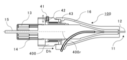
- FIGS. 3A and 3B are explanatory diagrams of the catheter 11.
- FIG. 3A is a diagram illustrating the entire catheter 11.
- FIG. 3B is an enlarged view of catheter 11.
- the catheter 11 includes a bending portion (bending body, catheter main body) 12 and a bending driving portion (catheter driving portion) 13 configured to bend the bending portion 12 .
- the bending driving portion 13 is configured to bend the bending portion 12 by receiving the driving force of the wire driving portion 300 via the connecting device 21 to be described later.
- the catheter 11 is stretched along the insertion direction of the catheter 11 with respect to the subject.
- the extending direction (longitudinal direction) of the catheter 11 is the same as the extending direction (longitudinal direction) of the bending portion 12 and the extending direction (longitudinal direction) of first to ninth drive wires (W11 to W33) described later.
- the bending drive section 13 includes a plurality of drive wires (drive lines, linear members, linear actuators) connected to the bending section 12 .
- the bending drive section 13 includes a first drive wire W11, a second drive wire W12, a third drive wire W13, a fourth drive wire W21, a fifth drive wire W22, a sixth drive wire W23, a seventh drive wire W23, and a seventh drive wire W23. It includes a wire W31, an eighth drive wire W32 and a ninth drive wire W33.
- Each of the first to ninth drive wires includes a held portion (held shaft, rod) Wa.
- the first drive wire W11 includes a first held portion Wa11.
- the second drive wire W12 includes a second held portion Wa12.
- the third drive wire W13 includes a third held portion Wa13.
- the fourth drive wire W21 includes a fourth held portion Wa21.
- the fifth drive wire W22 includes a fifth held portion Wa22.
- the sixth drive wire W23 includes a sixth held portion Wa23.
- the seventh drive wire W31 includes a seventh held portion Wa31.
- the eighth drive wire W32 includes an eighth held portion Wa32.
- the ninth drive wire W33 includes a ninth held portion Wa33.
- each of the first to ninth held portions (Wa11 to Wa33) has the same shape.
- Each of the first to ninth drive wires includes a flexible wire body (wire member, line body, linear body) Wb.
- the wire body Wb is a member that enables pushing and pulling of an object connected through the wire body Wb, and has a certain degree of rigidity. On the one hand, it is a member that can be deformed from a linear shape so that the bending portion 12 can be bent.
- the first drive wire W11 includes a first wire body Wb11.
- the second drive wire W12 includes a second wire body Wb12.
- the third drive wire W13 includes a third wire body Wb13.
- the fourth drive wire W21 includes a fourth wire body Wb21.
- the fifth drive wire W22 includes a fifth wire body Wb22.
- the sixth drive wire W23 includes a sixth wire body Wb23.
- the seventh drive wire W31 includes a seventh wire body Wb31.
- the eighth drive wire W32 includes an eighth wire body Wb32.
- the ninth drive wire W33 includes a ninth wire body Wb
- each of the first to third wire bodies has the same shape.
- Each of the fourth to sixth wire bodies has the same shape.
- Each of the seventh to ninth wire bodies has the same shape.
- the first to ninth wire bodies have the same shape except for the length.
- the first to ninth held parts (Wa11 to Wa33) are attached to the proximal ends of the first to ninth wire bodies (Wb11 to Wb33).
- the first to ninth drive wires (W11 to W33) are inserted into the bending section 12 through wire guides 17 and fixed.
- the material of each of the first to ninth wire bodies is metal.
- the material of each of the first to ninth wire bodies may be resin.
- the material of each of the first to ninth wire bodies may contain metal and resin.
- any one of the first to ninth drive wires (W11 to W33) can be called a drive wire W as a linear member.
- each of the first to ninth drive wires (W11 to W33) has the same shape except for the length of the first to ninth wire bodies (Wb11 to Wb33).
- the bending portion 12 is a tubular member having flexibility and having a passage Ht for inserting a medical instrument.
- a wall surface of the curved portion 12 is provided with a plurality of wire holes for passing the first to ninth drive wires (W11 to W33) respectively.
- the wall surface of the curved portion 12 is provided with a first wire hole Hw11, a second wire hole Hw12, and a third wire hole Hw13.
- the wall surface of the curved portion 12 is provided with a fourth wire hole Hw21, a fifth wire hole Hw22, and a sixth wire hole Hw23.
- the wall surface of the curved portion 12 is provided with a seventh wire hole Hw31, an eighth wire hole Hw32, and a ninth wire hole Hw33.
- the first to ninth wire holes Hw respectively correspond to the first to ninth drive wires (W11 to W33).
- the number after the symbol Hw indicates the number of the corresponding drive wire.
- the first drive wire W11 is inserted into the first wire hole Hw11.
- any one of the first to ninth wire holes can be called a wire hole Hw.
- each of the first to ninth wire holes has the same shape.
- the bending portion 12 has an intermediate region 12a and a bending region 12b.
- the bending region 12b is arranged at the distal end of the bending section 12, and the first guide ring J1, the second guide ring J2 and the third guide ring J3 are arranged in the bending region 12b.
- the bending area 12b is an area in which the bending magnitude and direction of the bending portion 12 can be controlled by moving the first guide ring J1, the second guide ring J2, and the third guide ring J3 by the bending drive section 13. say.
- FIG. 3B is drawn with part of the curved portion 12 covering the first to third guide rings (J1 to J3) omitted.
- the bending portion 12 includes a plurality of auxiliary rings (not shown).
- the first guide ring J1, the second guide ring J2, and the third guide ring J3 are fixed to the wall surface of the curved portion 12 in the curved region 12b.
- the plurality of auxiliary rings are arranged between the first guide ring J1 and the second guide ring J2 and between the second guide ring J2 and the third guide ring J3.
- the medical instrument is guided to the tip of the catheter 11 by the passageway Ht, first to third guide rings (J1 to J3), and multiple auxiliary rings.
- Each of the first to ninth drive wires is fixed to each of the first to third guide rings (J1 to J3) through the intermediate region 12a.
- the first drive wire W11, the second drive wire W12, and the third drive wire W13 are fixed to the first guide ring J1.
- a fourth drive wire W21, a fifth drive wire W22, and a sixth drive wire W23 pass through the first guide ring J1 and the plurality of auxiliary rings and are fixed to the second guide ring J2.
- a seventh drive wire W31, an eighth drive wire W32, and a ninth drive wire W33 pass through the first guide ring J1, the second guide ring J2, and the plurality of auxiliary rings, and are fixed to the third guide ring J3. .
- the medical device 1 can bend the bending portion 12 in a direction intersecting the extending direction of the catheter 11 by driving the bending driving portion 13 with the wire driving portion 300 . Specifically, by moving each of the first to ninth drive wires (W11 to W33) in the extending direction of the bending portion 12, the bending portion is moved through the first to third guide rings (J1 to J3).
- the twelve curved regions 12b can be curved in a direction transverse to the stretch direction.
- the user can insert the catheter 11 to the target portion inside the target by using at least one of moving the medical device 1 manually or by the moving stage 2a and bending the bending portion 12.
- the first to ninth drive wires move the first to third guide rings (J1 to J3) to bend the bending portion 12.
- Any one or two of the first to third guide rings (J1 to J3) and the drive wires fixed thereto may be omitted.
- the catheter 11 has seventh to ninth drive wires (W31 to W33) and a third guide ring J3, first to sixth drive wires (W11 to W23) and first to second guide rings ( J1 to J2) may be omitted. Further, the catheter 11 has fourth to ninth drive wires (W21 to W33) and second to third guide rings (J2 to J3), and has first to third drive wires (W11 to W13) and a 1 guide ring J1 may have the structure omitted.
- the catheter 11 may be configured to drive one guide ring with two drive wires. Also in this case, the number of guide rings may be one, or more than one.
- FIGS. 4A and 4B are explanatory diagrams of the catheter unit 100.
- FIG. FIG. 4A is an explanatory diagram of the catheter unit 100 in a state where the wire cover 14, which will be described later, is in the cover position.
- FIG. 4B is an explanatory diagram of the catheter unit 100 in which the wire cover 14, which will be described later, is in the exposed position.
- the catheter unit 100 has a bending portion 12 , a catheter 11 having a bending drive portion 13 , and a proximal end cover 16 that supports the proximal end of the catheter 11 .
- the catheter unit 100 includes a cover (wire cover) 14 for covering and protecting first to ninth drive wires (W11 to W33) as a plurality of drive wires.
- the catheter unit 100 is attachable/detachable with respect to the base unit 200 along the attachment/detachment direction DE.
- the direction in which the catheter unit 100 is attached to the base unit 200 and the direction in which the catheter unit 100 is removed from the base unit 200 are parallel to the attachment/detachment direction DE.
- the proximal end cover (frame body, bending portion housing, catheter housing) 16 is a cover that partially covers the catheter 11 .
- the proximal end cover 16 has a tool hole 16a for inserting medical instruments into the passageway Ht of the flexure 12 .
- the wire cover 14 is provided with a plurality of exposure holes (wire cover holes, cover holes) through which the first to ninth drive wires (W11 to W33) are passed.
- the wire cover 14 has a first exposure hole 14a11, a second exposure hole 14a12, a third exposure hole 14a13, a fourth exposure hole 14a21, a fifth exposure hole 14a22, a sixth exposure hole 14a23, a seventh exposure hole 14a31, and an eighth exposure hole.
- An exposure hole 14a32 and a ninth exposure hole 14a33 are provided.
- the first to ninth exposure holes (14a11 to 14a33) respectively correspond to the first to ninth drive wires (W11 to W33).
- the numbers after the reference numerals 14a indicate the numbers of the corresponding drive wires. For example, the first drive wire W11 is inserted into the first exposure hole 14a11.
- any one of the first to ninth exposure holes (14a11 to 14a33) can be called an exposure hole 14a.
- each of the first to ninth exposure holes (14a11 to 14a33) has the same shape.
- the wire cover 14 can move between a cover position (see FIG. 14A) covering the first to ninth drive wires (W11 to W33) and a cover retracted position (see FIG. 14B) retracted from the cover position.
- the cover retracted position can also be called an exposed position where the first to ninth drive wires (W11 to W33) are exposed.
- the wire cover 14 Before attaching the catheter unit 100 to the base unit 200, the wire cover 14 is positioned at the cover position. When the catheter unit 100 is attached to the base unit 200, the wire cover 14 moves from the cover position to the exposed position along the attachment/detachment direction DE.
- the wire cover 14 is retained at the exposed position after being moved from the covered position to the exposed position. Therefore, even if the catheter unit 100 is removed from the base unit 200 after attaching the catheter unit 100 to the base unit 200, the wire cover 14 is kept in the exposed position.
- the wire cover 14 may be configured to return to the cover position after being moved from the cover position to the exposed position.
- catheter unit 100 may include a biasing member that biases wire cover 14 from the exposed position toward the covered position. In this case, when the catheter unit 100 is removed from the base unit 200 after attaching the catheter unit 100 to the base unit 200, the wire cover 14 is moved from the exposed position to the covered position.
- the first to ninth held portions (Wa11 to Wa33) of the first to ninth drive wires (W11 to W33) are exposed.
- connection between the bending drive section 13 and a connecting device 21, which will be described later, is permitted.
- the first to ninth held portions (Wa11 to Wa33) of the first to ninth driving wires (W11 to W33) are exposed through the first to ninth exposure holes (14a11 to 14a33). protrude. More specifically, the first to ninth held portions (Wa11 to Wa33) protrude from the first to ninth exposure holes (14a11 to 14a33) in the mounting direction Da, which will be described later.
- the first to ninth drive wires (W11 to W33) are arranged along a circle (virtual circle) having a predetermined radius.
- the catheter unit 100 has a key shaft (key, catheter side key) 15 .
- the key shaft 15 extends in the attachment/detachment direction DE.
- the wire cover 14 is provided with a shaft hole 14b through which the key shaft 15 passes.
- the key shaft 15 can be engaged with a key receiving portion 22, which will be described later. By engaging the key shaft 15 with the key receiving portion 22, the movement of the catheter unit 100 with respect to the base unit 200 is achieved in the circumferential direction of the circle (virtual circle) in which the first to ninth drive wires (W11 to W33) are arranged. , is limited to a given range.
- the first to ninth drive wires (W11 to W33) are arranged outside the key shaft 15 so as to surround the key shaft 15 when viewed in the attachment/detachment direction DE.
- the key shaft 15 is arranged inside a circle (virtual circle) in which the first to ninth drive wires (W11 to W33) are arranged. Therefore, the key shaft 15 and the first to ninth drive wires (W11 to W33) can be arranged in a space-saving manner.
- the catheter unit 100 includes an operation section 400.
- the operation section 400 is configured to be movable (rotatable) with respect to the proximal end cover 16 and the bending drive section 13 .
- the operation unit 400 is rotatable around a rotation axis 400r.
- a rotating shaft 400r of the operation unit 400 extends in the attachment/detachment direction DE.
- the operation section 400 is configured to be movable (rotatable) with respect to the base unit 200 . More specifically, the operation unit 400 is configured to be movable (rotatable) with respect to the base housing 200f, the wire driving unit 300, and the connecting device 21, which will be described later.
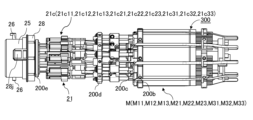
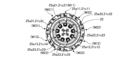
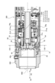
- FIGS. 5A to 5C are explanatory diagrams of the base unit 200 and the wire driving section 300.
- FIG. 5A is a perspective view showing the internal structure of the base unit 200.
- FIG. 5B is a side view showing the internal structure of base unit 200.
- FIG. FIG. 5C is a diagram of the base unit 200 viewed along the attachment/detachment direction DE.
- the medical device 1 has the base unit 200 and the wire driving section 300.
- the wire driving section 300 is accommodated in the base housing 200f and provided inside the base unit 200 .
- the base unit 200 has the wire drive section 300 .
- the wire drive unit 300 has a plurality of drive sources (motors, actuators).
- the wire driving section 300 includes a first driving source M11, a second driving source M12, a third driving source M13, a fourth driving source M21, a fifth driving source M22, a sixth driving source M23, a seventh driving source It has a source M31, an eighth drive source M32, and a ninth drive source M33.
- any one of the first to ninth drive sources (M11 to M33) can be called a drive source M.
- each of the first to ninth drive sources (M11 to M33) has the same configuration.
- the base unit 200 includes a coupling device 21.
- the coupling device 21 is housed in the base housing 200f.
- the coupling device 21 is connected to the wire driving section 300 .
- the connecting device 21 has a plurality of connecting parts.
- the connecting device 21 includes a first connecting portion 21c11, a second connecting portion 21c12, a third connecting portion 21c13, a fourth connecting portion 21c21, a fifth connecting portion 21c22, a sixth connecting portion 21c23, and a seventh connecting portion. 21c31, an eighth connecting portion 21c32, and a ninth connecting portion 21c33.
- any one of the first to ninth connecting portions (21c11 to 21c33) can be called the connecting portion 21c.
- each of the first to ninth connecting portions (21c11 to 21c33) has the same configuration.
- Each of the plurality of connecting parts is connected to each of the plurality of drive sources and driven by each of the plurality of drive sources.
- the first connecting portion 21c11 is connected to the first driving source M11 and driven by the first driving source M11.
- the second connecting portion 21c12 is connected to the second drive source M12 and driven by the second drive source M12.
- the third connecting portion 21c13 is connected to the third driving source M13 and driven by the third driving source M13.
- the fourth connecting portion 21c21 is connected to the fourth driving source M21 and driven by the fourth driving source M21.
- the fifth connecting portion 21c22 is connected to the fifth driving source M22 and driven by the fifth driving source M22.
- the sixth connecting portion 21c23 is connected to the sixth driving source M23 and driven by the sixth driving source M23.
- the seventh connecting portion 21c31 is connected to the seventh driving source M31 and driven by the seventh driving source M31.
- the eighth connecting portion 21c32 is connected to the eighth driving source M32 and driven by the eighth driving source M32.
- the ninth connecting portion 21c33 is connected to the ninth driving source M33 and driven by the ninth driving source M33.
- the connecting device 21 is connected with the bending driving section 13 including the first to ninth driving wires (W11 to W33).
- the bending driving portion 13 receives the driving force of the wire driving portion 300 via the connecting device 21 and bends the bending portion 12 .
- the drive wire W is connected to the connecting portion 21c via the held portion Wa.
- Each of the plurality of drive wires is connected to each of the plurality of connecting portions.
- the first held portion Wa11 of the first drive wire W11 is connected to the first connecting portion 21c11.
- the second held portion Wa12 of the second drive wire W12 is connected to the second connecting portion 21c12.
- the third held portion Wa13 of the third drive wire W13 is connected to the third connecting portion 21c13.
- the fourth held portion Wa21 of the fourth drive wire W21 is connected to the fourth connecting portion 21c21.
- the fifth held portion Wa22 of the fifth drive wire W22 is connected to the fifth connecting portion 21c22.
- the sixth held portion Wa23 of the sixth drive wire W23 is connected to the sixth connecting portion 21c23.
- the seventh held portion Wa31 of the seventh drive wire W31 is connected to the seventh connecting portion 21c31.
- the eighth held portion Wa32 of the eighth drive wire W32 is connected to the eighth connecting portion 21c32.
- the ninth held portion Wa33 of the ninth drive wire W33 is connected to the ninth connecting portion 21c33.
- the base unit 200 has a base frame 25.
- the base frame 25 is provided with a plurality of insertion holes through which the first to ninth drive wires (W11 to W33) are passed.
- the base frame 25 has a first insertion hole 25a11, a second insertion hole 25a12, a third insertion hole 25a13, a fourth insertion hole 25a21, a fifth insertion hole 25a22, a sixth insertion hole 25a23, a seventh insertion hole 25a31, and an eighth insertion hole 25a31.
- An insertion hole 25a32 and a ninth insertion hole 25a33 are provided.
- the first to ninth insertion holes (25a11 to 25a33) respectively correspond to the first to ninth drive wires (W11 to W33).
- the numbers after the reference numerals 25a indicate the numbers of the corresponding drive wires. For example, the first drive wire W11 is inserted into the first insertion hole 25a11.
- any one of the first to ninth insertion holes (25a11 to 25a33) can be called an insertion hole 25a.
- each of the first to ninth insertion holes (25a11 to 25a33) has the same shape.
- the base frame 25 is provided with a mounting opening 25b into which the wire cover 14 is inserted.
- First to ninth insertion holes (25a11 to 25a33) are arranged at the bottom of the mounting opening 25b.
- the base unit 200 includes a motor frame 200b, a first bearing frame 200c, a second bearing frame 200d, and a third bearing frame 200e.
- the motor frame 200b, the first bearing frame 200c, the second bearing frame 200d and the third bearing frame 200e are connected.
- the base frame 25 has a key receiving portion (key hole, base side key, body side key) 22 for receiving the key shaft 15 .
- the engagement between the key shaft 15 and the key receiving portion 22 prevents the catheter unit 100 from being attached to the base unit 200 out of phase.
- the catheter unit 100 By engaging the key shaft 15 and the key receiving portion 22, the catheter unit 100 is shifted with respect to the base unit 200 in the circumferential direction of the circle (virtual circle) in which the first to ninth drive wires (W11 to W33) are arranged. Movement is restricted within a predetermined range.
- each of the first to ninth drive wires (W11 to W33) is inserted into the corresponding first to ninth insertion holes (25a11 to 25a33) and the corresponding first to ninth connecting portions (21c11 to 21c33). , respectively.
- the drive wire W is prevented from engaging with the insertion hole 25a different from the corresponding insertion hole 25a and with the connecting portion 21c different from the corresponding connection portion 21c.
- the user By engaging the key shaft 15 and the key receiving portion 22, the user connects the first to ninth drive wires (W11 to W33) to the first to ninth connecting portions (21c11 to 21c33), respectively. can be correctly concatenated to Therefore, the user can easily attach the catheter unit 100 to the base unit 200 .
- the key shaft 15 has a convex portion that protrudes in a direction intersecting the attachment/detachment direction DE, and the key receiving portion 22 has a concave portion into which the convex portion is inserted.
- the position where the protrusion and the recess are engaged is the position where the drive wire W is engaged with the corresponding insertion hole 25a and the corresponding connecting part 21c.
- the key shaft 15 can be arranged on either one of the base unit 200 and the catheter unit 100, and the key receiving portion 22 can be arranged on the other.
- the key shaft 15 may be arranged on the base unit 200 side and the key receiving portion 22 may be arranged on the catheter unit 100 side.
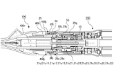
- FIGS. 6A to 6C are explanatory diagrams of the wire driving section 300, the connecting device 21, and the bending driving section 13.
- FIG. 6A is a perspective view of the drive source M, the connecting portion 21c, and the drive wire W.
- FIG. 6B is an enlarged view of the connecting portion 21c and the drive wire W.
- FIG. 6C is a perspective view showing the connection of the wire driving section 300, the connecting device 21, and the bending driving section 13.
- the configurations in which the first to ninth drive wires (W11 to W33) and the first to ninth connecting portions (21c11 to 21c33) are connected are the same. Also, the configuration in which each of the first to ninth connecting portions (21c11 to 21c33) and each of the first to ninth driving sources (M11 to M33) are connected is the same. Therefore, in the following description, one driving wire W, one connecting portion 21c, and one driving source M are used, and a configuration in which these are connected will be described.
- the drive source M has an output shaft Ma and a motor body Mb that rotates the output shaft Ma in the rotation direction Rm.
- a spiral groove is provided on the surface of the output shaft Ma.
- the output shaft Ma has a so-called screw shape.
- the motor main body Mb is fixed to the motor frame 200b.
- the connecting portion 21c has a tractor 21ct connected to the output shaft Ma and a tractor support shaft 21cs that supports the tractor 21ct.
- the tractor support shaft 21cs is connected to the connection base 21cb.
- the connecting portion 21c has a leaf spring 21ch as a holding portion for holding the held portion Wa of the driving wire W.
- the drive wire W passes through the insertion hole 25a and is engaged with the connecting portion 21c. More specifically, the held portion Wa engages with the plate spring 21ch.
- the leaf spring 21ch can take a state (fixed state) in which the held portion Wa is fixed while being held (fixed state) and a state in which the held portion Wa is released (released state).
- the connecting portion 21c has a pressing member 21cp as a switching portion.
- the pressing member 21cp includes a gear portion 21cg as a cam gear that meshes with a tooth portion 29g (see FIG. 10) of the planetary carrier 53, which will be described later, and a cam 21cc as a cam portion (pressing portion) for pressing the plate spring 21ch. have.
- the cam 21cc rotates integrally with the gear portion 21cg.
- the cam 21cc can move with respect to the plate spring 21ch.
- the leaf spring 21ch is switched between a fixed state (holding state) and a released state.
- the connecting portion 21c is supported by a first bearing B1, a second bearing B2 and a third bearing B3.
- the first bearing B1 is supported by the first bearing frame 200c of the base unit 200.
- the second bearing B2 is supported by the second bearing frame 200d of the base unit 200.
- the third bearing B3 is supported by the third bearing frame 200e of the base unit 200.
- the first bearing B1, the second bearing B2, and the third bearing B3 are provided for each of the first to ninth connecting portions (21c11 to 21c33).
- the connecting portion 21c Since the connecting portion 21c is restricted from rotating around the output shaft Ma, when the output shaft Ma rotates, the helical groove of the output shaft Ma causes the tractor 21ct to rotate along the rotation axis direction of the output shaft Ma. force acts. As a result, the connecting portion 21c moves along the rotation axis direction of the output shaft Ma (the Dc direction). As the connecting portion 21c moves, the drive wire W moves and the bending portion 12 bends. At this time, by switching the rotation direction of the drive source M, the connection part 21c can drive the drive wire W in both the direction of pushing the drive wire W and the direction of pulling the drive wire W.
- the output shaft Ma and the tractor 21ct constitute a so-called feed screw that converts rotary motion transmitted from the drive source M into linear motion by means of a screw.
- the output shaft Ma and the tractor 21ct are sliding screws, but they may be ball screws.
- each of the first to ninth drive wires (W11 to W33) and each of the first to ninth connecting portions (21c11 to 21c33) are connected. be done.
- the control unit 3 can control each of the first to ninth drive sources (M11 to M33) independently of each other. That is, any one of the first to ninth drive sources (M11 to M33) can operate or stop independently regardless of whether the other drive sources are in a stopped state. can be done. In other words, the controller 3 can control each of the first to ninth drive wires (W11 to W33) independently of each other. As a result, each of the first to third guide rings (J1 to J3) is controlled independently of each other, allowing the bending region 12b of the bending portion 12 to bend in any direction.
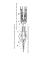
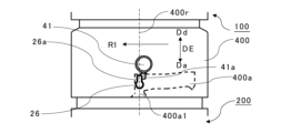
- FIGS. 7A and 7B are explanatory diagrams of mounting of the catheter unit 100.
- FIG. 7A is a view before the catheter unit 100 is attached to the base unit 200.
- FIG. 7B is a view after catheter unit 100 is attached to base unit 200.
- FIG. 7A is a view before the catheter unit 100 is attached to the base unit 200.
- the attachment/detachment direction DE of the catheter unit 100 is the same as the direction of the rotation shaft 400r of the operation section 400.
- the direction in which the catheter unit 100 is attached to the base unit 200 is referred to as the attachment direction Da.
- the direction in which the catheter unit 100 is removed from the base unit 200 is referred to as the removal direction Dd.
- the wire cover 14 is positioned at the cover position. At this time, the wire cover 14 is positioned so that the first to ninth drive wires are not projected from the first to ninth exposure holes (14a11 to 14a33) of the wire cover 14 so that the first to ninth held portions (Wa11 to Wa33) do not protrude from the first to ninth exposure holes (14a11 to 14a33). (W11 to W33) are covered. Therefore, before the catheter unit 100 is attached to the base unit 200, the first to ninth drive wires (W11 to W33) can be protected.
- the key shaft 15 is engaged with the key receiving portion 22.
- a key shaft 15 protrudes from the wire cover 14 .
- the wire cover 14 does not engage with the mounting opening 25b. That is, when the phase of the catheter unit 100 with respect to the base unit 200 is in a phase where the key shaft 15 and the key receiving portion 22 cannot be engaged, the wire cover 14 is not engaged with the mounting opening 25b and is positioned at the cover position. is preserved. Therefore, even when the catheter unit 100 is moved so that the key shaft 15 and the key receiving portion 22 are engaged, the first to ninth drive wires (W11 to W33) are protected.
- the catheter unit 100 is attached to the base unit 200 when the key shaft 15 and the key receiving portion 22 are engaged and the catheter unit 100 is moved with respect to the base unit 200 in the attachment direction Da. Attaching the catheter unit 100 to the base unit 200 moves the wire cover 14 to the exposed position. In this embodiment, the wire cover 14 contacts the base frame 25 to move from the cover position to the exposed position (see FIG. 7B).
- the wire cover 14 comes into contact with the base frame 25 and stops.
- the wire cover 14 in the catheter unit 100 moves relative to the portion other than the wire cover 14 .
- the wire cover 14 moves from the cover position to the exposed position.
- the held portion Wa of the drive wire W protrudes from the exposure hole 14a of the wire cover 14 and is inserted into the insertion hole 25a. Then, the held portion Wa engages with the leaf spring 21ch of the connecting portion 21c (see FIG. 6B).
- the catheter unit 100 can be removed by moving the catheter unit 100 relative to the base unit 200 in the removal direction Dd. Further, as will be described later, when the catheter unit 100 is simply attached to the base unit 200, the drive wire W and the connection portion 21c are unfixed.
- the catheter unit 100 is prevented from being removed from the base unit 200. Furthermore, by operating the operating portion 400 with the catheter unit 100 attached to the base unit 200, the bending driving portion 13 is fixed to the coupling device 21, and the bending driving portion 13 is connected to the wire driving portion via the coupling device 21. 300.
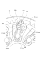
- FIG. 8 is a perspective view showing a connecting portion of the base unit 200 to the catheter unit 100.
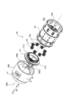
- FIG. 9 is a perspective view showing the planetary gear mechanism 50 built into the base unit 200.
- the base housing 200f is partially notched.
- FIG. 10 is an exploded perspective view showing the operating portion 400 and the planetary gear mechanism 50.
- FIG. 11 is an exploded perspective view showing the planetary gear mechanism 50.
- FIG. 12 is a cross-sectional view of the operating section 400 and the base unit 200 cut along the rotation axis 400r of the operating section 400.
- FIG. 13 is a cross-sectional view showing the 13A-13A section of FIG.
- the base unit 200 has a planetary gear mechanism 50 arranged near the base frame 25, as shown in FIGS.
- the planetary gear mechanism 50 has a sun gear 51 , an internal gear 52 , a planetary carrier 53 , and a plurality of (eight in this embodiment) planetary gears 54 .
- the sun gear 51 and the planetary carrier 53 are configured to be rotatable about the rotating shaft 400 r of the operating section 400 when the catheter unit 100 is attached to the base unit 200 .
- the sun gear 51 and the planetary carrier 53 are rotatably supported by the base frame 25 or the base housing 200f, for example, but are not limited to this, and may be supported by other members of the base unit 200.
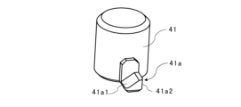
- the sun gear 51 has a gear portion 51a and a pair of projecting portions 51b, 51b that can be engaged with a pair of engaging portions 400j provided on the operating portion 400.
- the protrusions 51b, 51b extend along the attachment/detachment direction DE parallel to the axial direction of the rotating shaft 400r.
- most of the planetary gear mechanism 50 is covered with the base housing 200f, and only the projections 51b, 51b of the sun gear 51 are exposed to the outside. Therefore, it is possible to prevent the user from touching the gear portion of the planetary gear mechanism 50 and the invasion of dust and debris into the planetary gear mechanism 50 , thereby reducing damage to the planetary gear mechanism 50 . In addition, user safety can be improved.
- the internal gear 52 is provided integrally with the inner peripheral surface of the base housing 200f (see FIG. 11) and fixed to the base housing 200f.
- the planetary carrier 53 has a plurality of (eight in the present embodiment) shafts 53a that rotatably support the plurality of planetary gears 54, and a plurality of teeth 29g formed on the inner peripheral surface 53b. ing.
- the plurality of shaft portions 53a extend parallel to the rotation shaft 400r.
- a plurality of tooth portions 29g as output gears are arranged downstream of the sun gear 51, the internal gear 52, and the planetary gear 54 in the attachment direction Da within the attachment/detachment direction DE.
- the protruding portion 51b of the sun gear 51 engages with the engaging portion 400j of the operating portion 400. Accordingly, when the operating portion 400 rotates, the rotation of the operating portion 400 is transmitted to the sun gear 51 .
- the sun gear 51 rotates concentrically with the operating portion 400 .
- the gear portion 51a of the sun gear 51 meshes with each planetary gear 54, and each planetary gear 54 meshes with an internal gear 52 fixed to the base housing 200f. ing. Therefore, the rotation of the sun gear 51 is decelerated and output to the planetary carrier 53 via the planetary gear 54 . That is, the sun gear 51 is an input member (input portion) that rotates when the rotation of the operating portion 400 is input, the internal gear 52 is a fixed member, and the planetary carrier 53 is a member that presses the transmitted rotation. 21cp is an output member (output section).
- a force applied by the user to the operation unit 400 is received by the sun gear 51 and transmitted from the sun gear 51 to the planetary carrier 53 via the planetary gears 54 .
- the internal gear 52 is fixed with respect to the base unit 200 so that its position within the base unit 200 does not change. Further, in the present embodiment, since eight planetary gears 54 are provided, these eight planetary gears 54 share the load, and the planetary gear mechanism 50 can be configured compactly and have a long service life.
- the sun gear 51 when the operating unit 400 is rotated in the direction of arrow Q1 (see FIG. 10) by the user, the sun gear 51 also rotates in the direction of arrow Q2 as shown in FIG.
- the planetary gear 54 meshing with the sun gear 51 and the internal gear 52 rotates (revolves) in the direction of the arrow Q4 about the rotation axis 400r while rotating (revolving) about the shaft portion 53a in the direction of the arrow Q3.
- the planetary carrier 53 that supports the planetary gear 54 also rotates in the arrow Q4 direction about the rotation shaft 400r.
- the directions of arrows Q1, Q2, and Q4 are the same directions of rotation about the rotation shaft 400r.
- the direction of arrow Q3 is the direction of rotation opposite to the directions of arrows Q1, Q2, and Q4.
- the planetary carrier 53 rotates in conjunction with the operation unit 400, and the planetary gear mechanism 50 reduces the rotation of the operation unit 400 operated by the user and transmits it to the planetary carrier 53.
- the planetary gear mechanism 50 is transmitted from the operation unit 400 such that when the operation unit 400 rotates by the first rotation angle, the planet carrier 53 rotates by a second rotation angle that is smaller than the first rotation angle. slow down the rotation. More specifically, the rotation of the operation unit 400 is transmitted to the sun gear 51 in the same rotation, and the rotation of the sun gear 51 is transmitted to the planetary carrier 53 at a predetermined reduction ratio.
- This speed reduction ratio is calculated by (z1+z2)/z1, where z1 and z2 are the numbers of teeth of the gear portion 51a of the sun gear 51 and the internal gear 52, respectively.
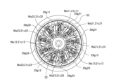
- FIG. 14A and 14B are diagrams for explaining the connection between the catheter unit 100 and the base unit 200.
- FIG. 14A is a cross-sectional view of catheter unit 100 and base unit 200 taken along rotation axis 400r.
- FIG. 14B is a cross-sectional view of the base unit 200 cut in a direction orthogonal to the rotating shaft 400r at the connecting portion 21c.
- 15, 16, 17, 18, and 19 are diagrams illustrating fixing of the drive wire W by the connecting portion 21c.
- the planetary gear mechanism 50 decelerates the rotation of the operating portion 400 operated by the user and transmits it to the planetary carrier 53 .
- a tooth portion 29g provided on the inner peripheral surface 53b of the planetary carrier 53 meshes with the gear portion 21cg of the pressing member 21cp.
- the cam 21cc of the pressing member 21cp presses the plate spring 21ch, and the plate spring 21ch (connecting portion 21c) is switched between a fixed state and a released state.
- each of the first to ninth connecting portions fixes each of the first to ninth drive wires (W11 to W33). and a state in which each of the first to ninth drive wires (W11 to W33) is released.
- Each of the plurality of tooth portions (action portion, switching gear portion) 29g provided on the planetary carrier 53 is engaged with the gear portion 21cg of the pressing member 21cp of each of the first to ninth connecting portions (21c11 to 21c33). match.
- the plurality of teeth provided on the planetary carrier 53 in this embodiment are a first tooth 29g11, a second tooth 29g12, a third tooth 29g13, a fourth tooth 29g21, and a fifth tooth. 29g22, a sixth tooth 29g23, a seventh tooth 29g31, an eighth tooth 29g32 and a ninth tooth 29g33.
- Each of the first to ninth tooth portions (29g11 to 29g33) is formed with a gap therebetween.
- the first tooth portion 29g11 meshes with the gear portion 21cg of the first connecting portion 21c11.
- the second tooth portion 29g12 meshes with the gear portion 21cg of the second connecting portion 21c12.
- the third tooth portion 29g13 meshes with the gear portion 21cg of the third connecting portion 21c13.
- the fourth tooth portion 29g21 meshes with the gear portion 21cg of the fourth connecting portion 21c21.
- the fifth tooth portion 29g22 meshes with the gear portion 21cg of the fifth connecting portion 21c22.
- the sixth tooth portion 29g23 meshes with the gear portion 21cg of the sixth connecting portion 21c23.
- the seventh tooth portion 29g31 meshes with the gear portion 21cg of the seventh connecting portion 21c31.
- the eighth tooth portion 29g32 meshes with the gear portion 21cg of the eighth connecting portion 21c32.
- the ninth tooth portion 29g33 meshes with the gear portion 21cg of the ninth connecting portion 21c33.
- any one of the first to ninth tooth portions (29g11 to 29g33) can be called a tooth portion 29g.
- each of the first to ninth tooth portions (29g11 to 29g33) has the same configuration.
- the configurations in which the first to ninth drive wires (W11 to W33) and the first to ninth connecting portions (21c11 to 21c33) are connected are the same. Also, the configuration in which each of the first to ninth connecting portions (21c11 to 21c33) and each of the first to ninth tooth portions (29g11 to 29g33) are connected is the same. Therefore, in the following description, one driving wire W, one connecting portion 21c, and one tooth portion 29g are used to connect them.
- the gear portion 21cg is moved by the tooth portion 29g, thereby rotating the pressing member 21cp and causing the cam 21cc to move between the pressing position and the retracted position. and move to.
- the planetary carrier 53 rotates via the sun gear 51 and the planetary gear 54 of the planetary gear mechanism 50 .
- the rotation of the planetary carrier 53 causes the first to ninth connecting portions (21c11 to 21c33) to operate. That is, the first to ninth connecting portions (21c11 to 21c33) can be operated by rotating one operating portion 400.
- the operation section 400 can move between a fixed position (locked position) and a removed position. Further, as will be described later, the operating section 400 can move to the release position while the catheter unit 100 is attached to the base unit 200 . With respect to the circumferential direction of the operating portion 400, the release position is positioned between the fixed position and the removal position. The catheter unit 100 is attached to the base unit 200 with the operating portion 400 positioned at the removal position.
- the drive wire W is unlocked from the connecting portion 21c.
- This state is called a released state of the connecting portion 21c.
- the state in which the drive wire W is fixed (locked) to the connecting portion 21c is referred to as the fixed state of the connecting portion 21c. That is, the state of the connecting portion 21c when the leaf spring 21ch is in the fixed state (holding state) is called the fixed state (holding state), and the state of the connecting portion 21c when the leaf spring 21ch is in the released state is called the released state.
- each tooth portion 29g of the planetary carrier 53 has three teeth Za1, Za2 and Za3, and the gear portion 21cg of each pressing member 21cp has four teeth Zb1, Zb2 and Zb3. , Zb4.
- the catheter unit 100 After attaching the catheter unit 100 to the base unit 200 and before operating the operation section 400, the catheter unit 100 can be removed from the base unit 200.
- a state in which the catheter unit 100 can be removed from the base unit 200 is hereinafter referred to as a detachable state.
- FIG. 15 is a diagram showing the state of the planetary carrier 53 and the connecting portion 21c in the detachable state.
- FIG. 15 is a diagram showing the planetary carrier 53 and the connecting portion 21c when the operation portion 400 is at the removal position.
- the leaf spring 21ch of the connecting portion 21c has a fixed portion 21cha fixed to the connecting base 21cb and a pressed portion 21chb that contacts the cam 21cc of the pressing member 21cp.
- the leaf spring 21ch has a first portion 21chd1 and a second portion 21chd2.
- the cam 21cc has a holding surface 21cca and a pressing surface 21ccb. With respect to the radial direction of rotation of the pressing member 21cp, the holding surface 21cca is arranged at a position closer to the center of rotation 21cpc of the pressing member 21cp than the pressing surface 21ccb.
- the plate spring 21ch is held at a position where the pressed portion 21chb contacts the holding surface 21cca. Further, the teeth Za1 of the planetary carrier 53 and the teeth Zb1 of the gear portion 21cg are stopped with a clearance La between them.
- the direction in which the operation unit 400 moves from the removal position to the release position and the fixing position is called the lock direction (fixing direction), and the direction in which the operation unit 400 moves from the fixing position to the release position and the removal position is called the release direction. called direction.
- the operation part 400 rotates in the release direction from the release position and moves to the removal position.
- the operating portion 400 rotates in the locking direction from the unlocked position and moves to the fixed position.
- the connecting part 21c When the catheter unit 100 is attached to the base unit 200 and the operation part 400 is at the removal position, the connecting part 21c is in a released state, and the fixing of the driving wire W by the connecting part 21c is released.
- the cam 21cc When the connecting portion 21c is in the released state, the cam 21cc is located at a retracted position retracted from the pressing position described later. At this time, the fixing of the held portion Wa by the leaf spring 21ch is released.
- the force with which the first portion 21chd1 and the second portion 21chd2 tighten the held portion Wa when the connecting portion 21c is in the released state is the same as that of the first portion 21chd1 and the second portion 21chd2 when the connecting portion 21c is in the fixed state. It is smaller than the force with which the holding part Wa is tightened.
- the held portion Wa can be pulled out from between the first portion 21chd1 and the second portion 21chd2.
- the first portion 21chd1 and the second portion 21chd2 do not generate a force to tighten the held portion Wa (a state in which the force is zero).
- a gap is preferably formed between at least one of the first portion 21chd1 and the second portion 21chd2 and the held portion Wa when the connecting portion 21c is in the released state.
- FIG. 16 is a diagram showing the state of the planetary carrier 53 and the connecting portion 21c when the operation portion 400 is rotated in the locking direction from the removal position.
- FIG. 16 is a diagram showing the state of the planetary carrier 53 and the connecting portion 21c when the operating portion 400 is at the release position.
- the entire catheter unit 100 (excluding the operating portion 400) remains in contact with the base unit 200 because the key shaft 15 and the key receiving portion 22 are engaged. rotation is restricted. That is, the operating portion 400 can rotate with respect to the entire catheter unit 100 (excluding the operating portion 400) and the base unit 200 in a stopped state.
- the tooth Zb2 of the gear portion 21cg is arranged at a position with a clearance Lz between it and the addendum circle (dotted line) of the tooth portion 29g of the planetary carrier 53 . Therefore, the planetary carrier 53 can rotate without interfering with the tooth Zb2.
- the connecting portion 21c is kept in the same state (released state) as shown in FIG.
- FIG. 17 shows the state of the planetary carrier 53 and the connecting portion 21c at that time.
- FIG. 17 is a diagram showing the state of the planetary carrier 53 and the connecting portion 21c when the operating portion 400 is rotated in the lock direction from the unlocked position.
- the tooth Za1 of the planetary carrier 53 and the tooth Zb1 of the gear portion 21cg come into contact with each other.
- the connecting portion 21c is in the same state as shown in FIGS. 15 and 16, and is kept in the released state.
- FIG. 18 is a diagram showing a state in which the pressing member 21cp is rotated by rotating the operating portion 400 in the locking direction. As shown in FIG. 18, when the operating portion 400 is further rotated in the locking direction from the state of FIG. 17, the planetary carrier 53 is further rotated clockwise.
- the reaction force of the leaf spring 21ch acting on the corner 21ccb1 acts on a position distant from the rotation center 21cpc of the pressing member 21cp, and the pressing member 21cp rotates clockwise. At this time, the pressing member 21cp rotates in the same direction as the direction rotated by the planetary carrier 53 rotating clockwise.
- FIG. 19 is a diagram showing the state of the planetary carrier 53 and the connecting portion 21c when the operation portion 400 is in the fixed position. As shown in FIG. 19, the pressing member 21cp is further rotated from the state shown in FIG. 18 by receiving the reaction force of the leaf spring 21ch.
- the pressing member 21cp stops when the pressing surface 21ccb of the cam 21cc and the pressed portion 21chb of the leaf spring 21ch are in surface contact. That is, the pressing surface 21ccb and the surface of the pressed portion 21chb are aligned on the same plane.
- the connecting portion 21c is in a fixed state.
- the cam 21cc of the pressing member 21cp is positioned at the pressing position, and the pressing surface 21ccb presses the pressed portion 21chb.
- the holding portion Wa is sandwiched between the first portion 21chd1 and the second portion 21chd2. That is, the leaf spring 21ch is pressed by the cam 21cc, and the held portion Wa is tightened by the leaf spring 21ch. As a result, the held portion Wa is fixed by the plate spring 21ch.
- the first portion 21chd1 and the second portion 21chd2 of the leaf spring 21ch press the held portion Wa at positions separated from each other. Further, a bent portion 21chc connecting the first portion 21chd1 and the second portion 21chd2 is arranged between the first portion 21chd1 and the second portion 21chd2. The bent portion 21chc is arranged with a gap G from the held portion Wa. By doing so, the held portion Wa can be stably fixed by the first portion 21chd1 and the second portion 21chd2.
- resin or metal As the material of the plate spring 21ch, resin or metal can be used, but it is preferable to use metal.
- the tooth Za3 of the planetary carrier 53 and the tooth Zb4 of the gear portion 21cg are stopped at a position where a clearance Lc is generated between them.
- the tip surface of the tooth Za3 is positioned downstream in the releasing direction with respect to the cylindrical surface that is in contact with the tip surfaces of the other teeth Za1 and Za2 about the rotational axis (rotational axis 400r) of the planetary carrier 53. It is slanted away from the axis of rotation. As a result, when the planetary carrier 53 is rotated in the release direction from the state shown in FIG. It is possible.
- the operation part 400 located at the fixed position is rotated in the release direction.
- the planetary carrier 53 rotates counterclockwise from the state shown in FIG.
- the teeth Za3 of the planetary carrier 53 come into contact with the teeth Zb4 of the gear portion 21cg, and the pressing member 21cp is rotated counterclockwise.
- the fixation of the drive wire W by the connecting portion 21c is released.
- the operations of the planetary carrier 53 and the pressing member 21cp at this time are operations opposite to those described above. That is, the fixation of the drive wire W by the connection portion 21c is released by the operation opposite to the operation when the drive wire W is fixed by the connection portion 21c described above.
- the above operations are performed in each of the first to ninth connecting portions (21c11 to 21c33). That is, in the process of moving the operation part 400 from the detachment position to the fixed position, the movement (rotation) of the operation part 400 changes the first to ninth connecting parts (21c11 to 21c33) from the released state to the fixed state. In the process of moving the operating portion 400 from the fixed position to the detaching position, the movement (rotation) of the operating portion 400 causes the first to ninth connecting portions (21c11 to 21c33) to change from the fixed state to the released state. In other words, the user can switch between the released state and the fixed state of the plurality of connecting portions by operating one operating portion 400 .
- the user can easily attach/detach the catheter unit 100 to/from the base unit 200 . Furthermore, the medical device 1 can be simplified.
- a state in which the first to ninth drive wires (W11 to W33) are respectively fixed by the first to ninth connecting portions (21c11 to 21c33) is called a first state.
- a state in which the first to ninth connecting portions (21c11 to 21c33) are released from the first to ninth driving wires (W11 to W33) is called a second state.
- the first state and the second state are switched. That is, the first state and the second state are switched in conjunction with the movement of the operation unit 400 between the removal position and the fixing position.
- the planetary carrier 53 of the planetary gear mechanism 50 is configured to interlock with the operating section 400 .
- the sun gear 51 , the internal gear 52 and the planetary gears 54 of the planetary gear mechanism 50 function as transmission members for interlocking the operating section 400 and the planetary carrier 53 .
- the planetary gear mechanism 50 functions as an interlocking section interlocking with the operating section 400 so that the first state and the second state are switched in conjunction with the movement of the operating section 400 .
- the planetary carrier 53 of the planetary gear mechanism 50 moves a part of the plate spring 21ch (pressed portion 21chb) in conjunction with the movement of the operation portion 400. ) is moved with respect to the held portion Wa.
- the connection portion 21c is switched between a fixed state and a released state.
- the operation section 400 is configured to be movable between the removal position, the release position, and the fixing position with the catheter unit 100 attached to the base unit 200 .
- the release position is located between the removal position and the locking position.
- the operation unit 400 is switched between the first state and the second state in conjunction with the movement of the operation unit 400 between the release position and the fixed position.
- the operation unit 400 can move between the removal position and the fixed position by moving in a direction different from the attachment/detachment direction DE.
- the operation part 400 moves in a direction intersecting (preferably orthogonal to) the attachment/detachment direction DE to move between the removal position and the fixing position.
- the operation unit 400 rotates around a rotation shaft 400r extending in the attachment/detachment direction DE to move between the removal position and the fixed position. Therefore, the operability when the user operates the operation unit 400 is excellent.
- FIG. 20A to 20C are explanatory diagrams of the catheter unit 100 and the base unit 200.
- FIG. 20A is a cross-sectional view of catheter unit 100.
- FIG. 20B is a perspective view of the button 41.
- FIG. 20C is a perspective view of the base unit 200.
- FIG. 20A is a cross-sectional view of catheter unit 100.
- FIG. 20B is a perspective view of the button 41.
- FIG. 20C is a perspective view of the base unit 200.
- FIG. 21A to 21C are diagrams for explaining the operation of the operation unit 400.
- FIG. FIG. 21A is a diagram showing a state in which the operation unit 400 is at the removal position.
- FIG. 21B is a diagram showing a state in which the operating section 400 is at the release position.
- FIG. 21C is a diagram showing a state where the operation unit 400 is in the fixed position.
- FIG. 22A to 22C are cross-sectional views explaining the operation of the operation unit 400.
- FIG. FIG. 22A is a cross-sectional view showing a state in which the operating section 400 is at the removal position.
- FIG. 22B is a cross-sectional view showing a state in which the operating portion 400 is at the release position.
- FIG. 22C is a cross-sectional view showing a state in which the operating section 400 is in the fixed position.
- the connecting portion 21c When the operating portion 400 is at the fixed position, the connecting portion 21c is in a fixed state, and the held portion Wa of the drive wire W is fixed to the corresponding connecting portion 21c (see FIG. 19).
- the coupling portion 21c When the operating portion 400 is at the released position, the coupling portion 21c is in the released state, and the held portion Wa of the driving wire W and the coupling portion 21c are unlocked (see FIG. 16). In this state, the connection between the drive wire W and the wire drive section 300 is cut off. Therefore, when the catheter 11 receives an external force, the bending portion 12 can be freely bent without receiving resistance from the wire driving portion 300 .
- the catheter unit 100 is allowed to be removed from the base unit 200 when the operation part 400 is at the removal position.
- the catheter unit 100 can be attached to the base unit 200 while the operation section 400 is at the removal position.
- the connecting portion 21c is in the released state, and the locked portion Wa of the drive wire W and the connecting portion 21c are unlocked (see FIG. 15).
- the catheter unit 100 has an operating section biasing spring 43 that biases the operating section 400 , a button 41 as a moving member, and a button spring 42 that biases the button 41 .
- the operating portion biasing spring 43 is a compression spring.
- the operating portion 400 is urged in a direction Dh to approach the proximal end cover 16 by an operating portion urging spring 43 .
- the button 41 and the button spring 42 are provided in the operation section 400.
- the button 41 and the button spring 42 move together with the operation unit 400 when the operation unit 400 moves to the removal position, the release position, and the fixing position.
- the button 41 is configured to be movable with respect to the operation unit 400 in a direction intersecting with the direction of the rotation axis 400r of the operation unit 400.
- the button 41 is urged by a button spring 42 toward the outside of the catheter unit 100 (in the direction away from the rotating shaft 400r).
- the button 41 restricts movement of the operation unit 400 from the release position to the removal position. Further, by moving the button 41 with respect to the operation portion 400, the operation portion 400 is allowed to move from the release position to the removal position.
- the button 41 has a button projection (restricted portion) 41a.
- the button protrusion 41a has an inclined surface 41a1 and a regulated surface 41a2.
- the base unit 200 includes a base frame 25.
- a lock shaft 26 is provided on the base frame 25 .
- the lock shaft 26 has a lock projection (restriction portion) 26a.
- a plurality of lock shafts 26 are provided. All of the lock shafts 26 may have the lock projections 26a, or some of the lock shafts 26 may have the lock projections 26a.
- a lock groove 400a that engages with the lock shaft 26 is provided inside the operating portion 400.
- the lock groove 400a extends in a direction different from the attachment/detachment direction DE. In this embodiment, it extends in the direction of rotation of the operation unit 400 . It can also be said that the lock groove 400a extends in a direction crossing (perpendicular to) the attachment/detachment direction DE.
- the lock grooves 400a are provided for each of the plurality of lock shafts 26 .
- the operating portion 400 is positioned at the removal position, and the connecting portion 21c is in the released state (see FIG. 15). Therefore, the first to ninth drive wires (W11 to W33) are released from the first to ninth connecting portions (21c11 to 21c33). Further, as shown in FIG. 22A, the button projection 41a faces the lock projection 26a.
- the slope 41a1 of the button projection 41a comes into contact with the slope 26a1 of the lock projection 26a.
- the button 41 moves toward the inner side of the operation unit 400 (in the direction toward the rotating shaft 400r). Then, the button projection 41a climbs over the lock projection 26a, and the operating portion 400 moves to the release position (see FIG. 22B).
- the connecting portion 21c is in the released state (see FIG. 16). Therefore, the first to ninth drive wires (W11 to W33) are released from the first to ninth connecting portions (21c11 to 21c33).
- the operation unit 400 it is allowed to move the operation unit 400 from the removal position to the release position without operating the button 41 .
- the user does not need to operate the button 41 when moving the operation unit 400 from the removal position to the release position.
- the positioning portion 400a2 of the lock groove 400a is located at a position corresponding to the lock shaft 26 when the operation portion 400 is in the fixed position.
- the operation portion 400 is urged in the direction Dh to approach the proximal end cover 16 by an operation portion urging spring 43 .
- the positioning portion 400 a 2 is engaged with the lock shaft 26 .
- the held part Wa of the driving wire W is fixed to the connecting part 21c as described above.
- the connecting part 21c When the operation part is positioned at the fixed position, the connecting part 21c is in the fixed state (see FIG. 14). Therefore, the first to ninth drive wires (W11 to W33) are respectively fixed to the first to ninth connecting portions (21c11 to 21c33). In this state, the driving force from the wire driving section 300 can be transmitted to the bending driving section 13 . That is, the driving force from each of the first to ninth driving sources (M11 to M33) is applied to the first to ninth driving wires (W11 to W33) through the first to ninth connecting portions (21c11 to 21c33). can be transmitted to each of the
- the wall 400a3 forming the lock groove 400a is located upstream of the lock shaft 26 in the removal direction Dd of the catheter unit 100.
- the positioning portion 400a2 is positioned upstream of the lock shaft 26 in the removal direction Dd.
- the entrance 400a1 of the lock groove 400a is positioned upstream of the lock shaft 26 in the removal direction Dd.
- the operation part 400 When the operation part 400 is rotated in the release direction R2 while the operation part 400 is at the fixed position, the operation part 400 is positioned at the release position. While the operating portion 400 moves from the fixed position to the released position, the held portion Wa of the drive wire W is released from the connecting portion 21c as described above.
- the regulated surface 41a2 of the button projection 41a contacts the regulating surface 26a2 of the lock projection 26a (see FIG. 22B). In this state, rotation of the operating portion 400 in the release direction R2 is restricted. Moreover, removal of the catheter unit 100 from the base unit 200 is restricted.
- the regulated surface 41a2 separates from the regulating surface 26a2, and the button projection 41a climbs over the lock projection 26a. .
- the operation portion 400 is allowed to rotate in the release direction R2, and the operation portion 400 can move from the release position to the removal position.
- the connecting portion 21c When the operating portion 400 is positioned at the removal position, the connecting portion 21c is in the released state. Therefore, when the catheter unit 100 is removed from and attached to the base unit 200, the load acting on the drive wire W (for example, the resistance received by the connecting portion 21c) can be reduced. Therefore, the user can easily attach and detach the catheter unit 100 .
- the catheter unit 100 When the operating portion 400 is positioned at the released position, the catheter unit 100 is restricted from being removed from the base unit 200, and the connecting portion 21c is placed in the released state. As described above, when the connecting portion 21c is in the released state, the connection between the driving wire W and the wire driving portion 300 is cut off, and the bending portion 12 can be freely bent without receiving resistance from the wire driving portion 300. can.
- the user can stop driving the catheter 11 by the wire driving section 300 by positioning the operation section 400 at the release position while the catheter 11 is inserted inside the target. Furthermore, since the removal of the catheter unit 100 from the base unit 200 is restricted, the user can hold the base unit 200 and pull out the catheter 11 from inside the subject.
- the operation section 400 when the button 41 is not operated, the operation section 400 is restricted from moving from the release position to the removal position. Therefore, when the user moves the operation unit 400 from the fixed position to the release position, it is possible to prevent the user from accidentally moving the operation unit 400 to the removal position.
- the numbers of the lock protrusion 26a and the number of the buttons 41 are one each.
- the medical device 1 may have a plurality of lock projections 26a and buttons 41. FIG.
- the planetary gear mechanism 50 reduces the speed of the rotation of the operating portion 400 and transmits it to the gear portion 21cg of the pressing member 21cp. That is, the planetary gear mechanism 50 is a deceleration mechanism that decelerates and transmits the rotation of the operation unit 400 .
- the rotation angle of the planetary carrier 53 is smaller than the rotation angles of the operation unit 400 and the sun gear 51 . Therefore, when operating the operation unit 400 from the detached position to the fixed position, it is necessary to rotate the operation unit 400 against the biasing force of the plate spring 21ch. It is possible to improve the operability.
- the sun gear 51 and the planetary carrier 53 of the planetary gear mechanism 50 are configured to rotate concentrically with the operating portion 400 . Therefore, the space efficiency is good, and even if the planetary gear mechanism 50 is provided, the size of the device can be suppressed.
- the reduction ratio of the planetary gear mechanism 50 is set to 1.5 to 3.0.
- the reduction ratio of the planetary gear mechanism 50 is set to 2.4 so that the planetary carrier 53 rotates about 50° when the operation part 400 rotates about 120° between the removal position and the fixed position. .
- Rotating the operation unit 400 by 120° is an appropriate operation range that can be performed by a single action for the user. does not require a large operating force to transition between
- FIG. 23A is a skeleton diagram showing the planetary type planetary gear mechanism 50 described in FIGS. 8-13.
- FIG. 23B is a skeleton diagram showing a solar-type planetary gear mechanism 150.
- FIG. 23C is a skeleton diagram showing a star-shaped planetary gear mechanism 250.
- a solar-type planetary gear mechanism 150 which is a modification of the first embodiment, includes a planetary carrier 153 that rotatably supports a sun gear 151, an internal gear 152, and a plurality of planetary gears 154. and have In the solar-type planetary gear mechanism 150 , the rotation of the operating portion 400 (see FIG. 2) is input to the internal gear 152 . Also, the sun gear 151 is fixed to the base unit 200 . The internal gear 152 meshes with a plurality of planetary gears 154 , and the planetary carrier 153 rotates in the same direction as the internal gear 152 .
- the internal gear 152 is an input member (input portion) that rotates when the rotation of the operating portion 400 is input
- the sun gear 151 is a fixed member
- the planetary carrier 153 is a member that presses the transmitted rotation.
- 21cp is an output member (output section).
- a force applied by the user to the operation unit 400 is received by the internal gear 152 and transmitted from the internal gear 152 to the planetary carrier 153 via the planetary gears 154 .
- the sun gear 151 is fixed with respect to the base unit 200 so that its position within the base unit 200 does not change.
- the rotation angle of the planetary carrier 153 is smaller than the rotation angles of the operation part 400 and the internal gear 152 .
- a star-shaped planetary gear mechanism 250 which is another modified example of the first embodiment, rotatably supports a sun gear 251, an internal gear 252, and a plurality of planetary gears 254, as shown in FIG. 23C. and a planet carrier 253 that In the star-type planetary gear mechanism 250 , the rotation of the operating portion 400 (see FIG. 2) is input to the sun gear 251 . Also, the planetary carrier 253 is fixed to the base unit 200 . The sun gear 251 meshes with a plurality of planetary gears 254 , and the internal gear 252 meshes with the plurality of planetary gears 254 to rotate in a direction opposite to the sun gear 251 .
- the sun gear 251 is an input member (input unit) that rotates when the rotation of the operation unit 400 is input
- the planetary carrier 253 is a fixed member
- the internal gear 252 is a member that presses the transmitted rotation.
- 21cp is an output member (output section).
- a force applied to the operation unit 400 by the user is received by the sun gear 251 and transmitted from the sun gear 251 to the internal gear 252 via the planetary gears 254 .
- Planet carrier 253 is fixed relative to base unit 200 so that its position within base unit 200 does not change. According to the star-shaped planetary gear mechanism 250 , the rotation angle of the internal gear 252 is smaller than the rotation angles of the operating section 400 and the sun gear 251 .
- the planetary type planetary gear mechanism 50 and the solar type planetary gear mechanism 150 output the rotation input from the operation unit 400 as rotation in the same direction
- the star type planetary gear mechanism 250 receives the input from the operation unit 400. output the rotation in the opposite direction.
- these planetary gear mechanisms 50, 150, and 250 as reduction mechanisms reduce the speed of rotation of the operating portion 400 and transmit it to the gear portion 21cg of the pressing member 21cp. can be done.
- the planetary type planetary gear mechanism is preferable because the largest reduction ratio can be obtained.
- FIG. This embodiment differs from the first embodiment in that a stepped gear mechanism 350 is applied instead of the planetary gear mechanism 50 .
- elements with common reference numerals as in the first embodiment have substantially the same configuration and action as those described in the first embodiment, and mainly differ from the first embodiment. do.
- FIG. 24 is a perspective view showing the step gear mechanism 350.
- FIG. 25 is an exploded perspective view showing the step gear mechanism 350.
- the base unit 200 (see FIG. 8) has a stepped gear mechanism 350 arranged near the base frame 25, as shown in FIGS.
- the step gear mechanism 350 has an input gear 351, a plurality of (two in this embodiment) step gears 354, 354, and an output gear 353 as an output member (output section).
- the input gear 351 and the output gear 353 are configured to be rotatable about the rotating shaft 400 r of the operating section 400 when the catheter unit 100 is attached to the base unit 200 .
- These input gear 351 and output gear 353 are rotatably supported, for example, by the base frame 25 or the base housing 200f, but are not limited to this, and may be supported by other members of the base unit 200. Also, the step gears 354 , 354 are rotatably supported by the base frame 25 .
- the input gear 351 has a gear portion 351a and a pair of projecting portions 351b, 351b that can be engaged with a pair of engaging portions 400j (see FIG. 10) provided on the operating portion 400.
- the protrusions 351b, 351b extend along the attachment/detachment direction DE parallel to the axial direction of the rotating shaft 400r.
- the output gear 353 has a gear portion 353a formed on an inner peripheral surface 353b and a plurality of tooth portions 29g (see FIG. 15). The plurality of tooth portions 29g are arranged downstream of the input gear 351 and the gear portion 353a in the attachment direction Da within the attachment/detachment direction DE.
- Each stage gear 354 has a first gear portion 354a that meshes with the gear portion 351a of the input gear 351, and a second gear portion 354b that meshes with the gear portion 353a of the output gear 353. These first gears The portion 354a and the second gear portion 354b rotate together.
- the first gear portion 354a has a first number of teeth and the second gear portion 354b has a second number of teeth less than the first number of teeth.
- the protrusion 351b of the input gear 351 engages with the engaging portion 400j of the operating portion 400. Accordingly, when the operating portion 400 rotates, the rotation of the operating portion 400 is transmitted to the input gear 351 as an input member (input portion). Since the gear portion 351 a as the input gear portion of the input gear 351 meshes with the first gear portion 354 a of the step gear 354 , the rotation of the input gear 351 is transmitted to the step gear 354 . Further, since the second gear portion 354 b of the step gear 354 meshes with the gear portion 353 a as the output gear portion of the output gear 353 , the rotation of the step gear 354 is transmitted to the output gear 353 .
- a force applied to the operation unit 400 by the user is received by the input gear 351 and transmitted from the input gear 351 to the output gear 353 via the step gear 354 .
- the rotation angle of the output gear 353 is smaller than the rotation angles of the operation unit 400 and the input gear 351 .
- the rotation of the operating portion 400 is reduced by the stepped gear mechanism 350 so that the state of the leaf spring 21ch can be switched between the fixed state and the released state. It is transmitted to the gear portion 21cg. That is, the stepped gear mechanism 350 is a deceleration mechanism that decelerates and transmits the rotation of the operation unit 400 . Therefore, when operating the operation unit 400 from the detached position to the fixed position, it is necessary to rotate the operation unit 400 against the biasing force of the plate spring 21ch. It is possible to improve the operability.
- the stepped gear mechanism 350 can be configured with a small number of parts, and can achieve cost reduction, miniaturization, and high durability.
- the numbers of teeth of the first gear portion 354a and the second gear portion 354b of the stage gear 354 are z3 and z4, respectively, the number of teeth (third number of teeth) of the gear portion 351a of the input gear 351 is z5, and the output gear 353 Let z6 be the number of teeth (fourth number of teeth) of the gear portion 353a.
- the speed reduction ratio of the stepped gear mechanism 350 is calculated by (z3/z5) ⁇ (z6/z4).
- the step gear mechanism 350 In order to increase the reduction ratio of the step gear mechanism 350, the number of teeth of the first gear portion 354a and the second gear portion 354b of the step gear 354 is small and the reduction ratio (z3/z4) of the step gear 354 is large. Gear selection is preferred. In the present embodiment, since the reduction ratio (z3/z4) of the stage gear 354 is 2, the gear ratio (z6/z5) between the gear portion 351a of the input gear 351 and the gear portion 353a of the output gear 353 is 0. 0.5 or more, the step gear mechanism 350 can decelerate the rotation of the operation unit 400 .
- the ratio of the number of teeth of the gear portion 353a to the number of teeth of the gear portion 351a is the ratio of the number of teeth of the second gear portion 354b to the number of teeth of the first gear portion 354a (z4/z3).
- the operation unit 400 is configured to be rotatable around the rotation shaft 400r, but the present invention is not limited to this.
- the operation unit 400 may be configured to move the connecting portion 21c between the fixed state and the released state by linearly moving in parallel with the rotating shaft 400r (the attachment/detachment direction DE).
- the pressing member 21cp that is interlocked with the linear motion (movement) of the operation unit 400 is also preferably configured to linearly move, and is provided between the operation unit 400 and the pressing member 21cp.
- the speed reduction mechanism is also preferably of a direct acting type.
- a motion conversion mechanism for converting rotation and linear motion may be appropriately provided when transmitting the movement such as rotation and linear motion of the operation portion 400 to the gear portion 21cg via the reduction mechanism.
- Motion conversion mechanisms that convert rotation to linear motion include, for example, ball screws, rack and pinions, and timing belts.
- Motion conversion mechanisms that convert linear motion into rotation include, for example, a slider crank and a rack and pinion.
- the speed reduction mechanisms such as the planetary gear mechanisms 50, 150, 250 and the step gear mechanism 350 decelerate the movement (including rotation and linear motion) input from the operation unit 400, and the pressure member 21cp introduce.
- the deceleration mechanism has an output member configured to be driven by force transmitted from the operating portion 400 to move the pressing member 21cpp.
- the output member can be said to be a transmission member that transmits the force transmitted from the operating section 400 toward the pressing member 21cp.
- the deceleration mechanism decelerates the movement of the operating portion 400 and transmits it to the pressing member 21cp so as to switch the connecting portion 21c between the holding state and the released state. More specifically, in the case of a configuration in which the operation unit 400 and the output member rotate, when the operation unit 400 rotates by a first rotation angle as the first movement amount, the output member rotates by the first rotation angle. is rotated by a second rotation angle as a second smaller movement amount. In the case of a configuration in which the operation unit 400 and the output member move linearly, when the operation unit 400 moves in the linear movement direction by the first movement amount, the output member moves by a second movement smaller than the first movement amount. move by an amount.
- the deceleration mechanism decelerates the movement of the operation unit 400 and transmits it to the output member.
- the moving speed of the output member becomes smaller than the moving speed of the operating unit 400, and conversely, the force output by the output member relative to the force received by the operating unit 400 from the user is growing.
- the torque output by the output member is greater than the torque for moving the operation unit 400 .
- the operating section 400 is provided in the catheter unit 100, but it is not limited to this.
- the operation section 400 may be provided on the base unit 200 .
- the operation unit 400 and the input member (input unit) are configured separately, but the present invention is not limited to this.
- the operation section 400 may be provided on the base unit 200 and the input member (input section) may be integrally formed with the operation section 400 .
- the pressing member 21cp is moved by the output member.
- the pressing member 21cp is directly moved by the output member in any of the above embodiments, the present invention is not limited to this. That is, a transmission member may be provided between the output member and the pressing member 21cp, and the output member may move the pressing member 21cp via the transmission member.
- planetary gear mechanisms 50, 150, and 250 are used in the first embodiment, and Although the step gear mechanism 350 has been mentioned and described, it is not limited to this.
- a parallel shaft gear reducer combining spur gears, a helical reducer combining helical gears, a bevel gear reducer combining bevel gears, a worm reducer combining worm gears and worm wheels, etc. may be used as the reduction mechanism. good.
- the reduction mechanism is not limited to a combination of gears, and a belt pulley may be used.
- a direct acting type speed reducer using a fluid and a piston or the like may be used instead of using a rotating member.
- the planetary gear mechanism 50 having the eight planetary gears 54 decelerates the rotation of the operation unit 400, but the present invention is not limited to this.
- the number of planetary gears 54 may be 1 to 7 or 9 or more.
- a double pinion planetary gear mechanism may be applied instead of the single pinion planetary gear mechanism.
- a planetary roller mechanism may be applied in which each gear of the planetary gear mechanism 50 is replaced with a roller, and the rotation of each roller is controlled by a frictional force.
- the step gear mechanism 350 having the pair of step gears 354 decelerates the rotation of the operation unit 400, but the present invention is not limited to this.
- the step gear mechanism 350 may combine a plurality of step gears in series to decelerate the rotation of the operation section 400 .
- the bendable catheter 11 is used as an example of the object to be operated.
- the object to be operated is not limited to this, and may include an articulated robot or the like.
- the articulated robot includes, for example, a medical robot arm having a surgical instrument (forceps, pointed blade, etc.) at its tip.
- configuration 1 a driving source; a base unit comprising a connecting portion connected to the drive source; A bendable unit detachably attached to the base unit, the bendable unit is configured to be connectable to a bendable bending portion and the connecting portion, and driven by the drive source via the connecting portion, the a bendable unit comprising a linear member that bends the bending portion; an operation unit; a speed reduction mechanism including an output member driven by force transmitted from the operation unit;
- the connecting portion can transition between a holding state in which the linear member is held while the bendable unit is attached to the base unit, and a release state in which the holding of the linear member is released.
- the output member is configured to move by a second movement amount that is smaller than the first movement amount when the operation unit moves by a first movement amount.
- medical device. (Configuration 2)
- the operation unit is configured to be rotatable, The output member rotates by a second rotation angle as the second movement amount that is smaller than the first rotation angle when the operating portion rotates by a first rotation angle as the first movement amount.
- the speed reduction mechanism is a planetary gear mechanism having an input portion rotated by input of rotation of the operation portion, the output member, a fixed member fixed to the base unit, and a plurality of planetary gears, The output member is configured to output the rotation transmitted from the input section to the switching section, A medical device according to configuration 2.
- the input unit is a sun gear
- the output member is a planetary carrier that rotatably and orbitally supports the plurality of planetary gears meshing with the sun gear
- the fixed member is an internal gear that meshes with the plurality of planetary gears, A medical device according to configuration 3.
- composition 5 the input unit is an internal gear
- the output member is a planetary carrier that rotatably and revolvingly supports the plurality of planetary gears meshing with the internal gear
- the fixed member is a sun gear that meshes with the plurality of planetary gears
- a medical device according to configuration 3. the input unit is a sun gear; the output member is an internal gear that meshes with the plurality of planetary gears;
- the fixed member is a planetary carrier that supports the plurality of planetary gears rotatably and revolvingly.
- the speed reduction mechanism includes an input section that rotates when rotation of the operation section is input, the output member, and step gears that mesh with the input section and the output member, respectively,
- the output member is configured to output the rotation transmitted from the input section to the switching section,
- the stage gear has a first gear portion having a first number of teeth and meshing with the input portion, and a second gear portion having a second number of teeth smaller than the first number of teeth and meshing with the output member. a second gear portion;
- Composition 8 The input section has a third number of teeth and includes an input gear section that meshes with the first gear section, the output member includes an output gear portion having a fourth number of teeth and meshing with the second gear portion; the ratio of the fourth number of teeth to the third number of teeth is greater than the ratio of the second number of teeth to the first number of teeth; 8.
- a medical device according to configuration 7. Composition 9) The input unit engages with the operation unit and rotates concentrically and integrally with the operation unit. 8. The medical device of any one of configurations 3-7.
- the switching portion includes a cam portion that rotates to switch the holding portion between the holding state and the released state, and a cam gear that rotates integrally with the cam portion,
- the output member includes an output gear meshing with the cam gear, 10.
- the medical device of any one of configurations 3-9. Composition 11
- the operation section is provided on the bendable unit,
- the deceleration mechanism is provided in the base unit, and is moved by the operation section while the bendable unit is attached to the base unit.
- the holding portion is a leaf spring that sandwiches and holds the linear member in the held state. 12.
- the present invention is applicable to medical devices including, for example, catheter units.
- medical devices including, for example, catheter units.
- it is applicable to a medical device in which the catheter unit is detachably attached to the base unit.
Landscapes
- Health & Medical Sciences (AREA)
- Life Sciences & Earth Sciences (AREA)
- Surgery (AREA)
- Engineering & Computer Science (AREA)
- Animal Behavior & Ethology (AREA)
- Public Health (AREA)
- General Health & Medical Sciences (AREA)
- Veterinary Medicine (AREA)
- Biomedical Technology (AREA)
- Heart & Thoracic Surgery (AREA)
- Nuclear Medicine, Radiotherapy & Molecular Imaging (AREA)
- Molecular Biology (AREA)
- Medical Informatics (AREA)
- Biophysics (AREA)
- Optics & Photonics (AREA)
- Pathology (AREA)
- Physics & Mathematics (AREA)
- Radiology & Medical Imaging (AREA)
- Robotics (AREA)
- Pulmonology (AREA)
- Human Computer Interaction (AREA)
- Physiology (AREA)
- Otolaryngology (AREA)
- Mechanical Engineering (AREA)
- Signal Processing (AREA)
- Rehabilitation Therapy (AREA)
- Anesthesiology (AREA)
- Hematology (AREA)
- Media Introduction/Drainage Providing Device (AREA)
- Endoscopes (AREA)
Abstract
医療装置(1)は、駆動源(M)と、前記駆動源(M)に接続された連結部(21c)を備えるベースユニット(200)と、湾曲部(12)と、前記連結部(21c)を介して前記駆動源(M)によって駆動されることで前記湾曲部(12)を湾曲させる線状部材(W)と、を備える湾曲可能ユニット(100)と、操作部(400)と、前記操作部(400)から伝達された力によって駆動される出力部材(252)を備える減速機構(350)と、を有する。前記連結部(21c)は、保持状態と、解除状態と、の間で遷移可能な保持部(21ch)と、前記出力部材(252)によって移動され、前記保持部(21ch)を前記保持状態と前記解除状態との間で切り換える切換え部(21cp)と、を備える。前記出力部材(252)は、前記操作部(400)が第1の移動量だけ移動した場合に前記第1の移動量よりも小さい第2の移動量だけ移動するように構成される。
Description
本発明は、湾曲可能な湾曲部を有する医療装置に関する。
特許文献1には、変形部を有する被操作部と、変形部を変形させる操作部と、を備え、被操作部と操作部とが着脱可能な医療器具が開示されている。被操作部には、変形部を変形させるためのワイヤが設けられており、ワイヤには、被操作部側磁石が固定されている。操作部には、プーリに巻き掛けられたワイヤが設けられており、該ワイヤには、操作部側磁石が固定されている。被操作部が操作部に連結されている際には、被操作部側磁石と操作部側磁石とが互いに引き合い、操作部と被操作部に設けられたワイヤが連動する。
しかしながら、上記特許文献1の構成では、被操作部を操作部から取り外す際には、互いに引き合う被操作部側磁石と操作部側磁石の引力に抗して、使用者が被操作部を引っ張らなければならない。
本発明の一態様によると、医療装置は、駆動源と、前記駆動源に接続された連結部を備えるベースユニットと、前記ベースユニットに取り外し可能に装着される湾曲可能ユニットであって、湾曲可能な湾曲部と、前記連結部に連結可能に構成され、前記連結部を介して前記駆動源によって駆動されることで前記湾曲部を湾曲させる線状部材と、を備える湾曲可能ユニットと、操作部と、前記操作部から伝達された力によって駆動される出力部材を備える減速機構と、を有する。前記連結部は、前記湾曲可能ユニットが前記ベースユニットに装着された状態で前記線状部材を保持する保持状態と、前記線状部材の保持が解除された解除状態と、の間で遷移可能な保持部と、前記出力部材によって移動され、前記保持部を前記保持状態と前記解除状態との間で切り換える切換え部と、を備える。前記出力部材は、前記操作部が第1の移動量だけ移動した場合に前記第1の移動量よりも小さい第2の移動量だけ移動するように構成される。
本発明によれば、操作部の操作力を低減することができる。
本発明のその他の特徴及び利点は、添付図面を参照とした以下の説明により明らかになるであろう。なお、添付図面においては、同じ若しくは同様の構成には、同じ参照番号を付す。
以下、本開示に係る実施形態について、図面を参照しながら説明する。
[第1実施形態]
<医療システム及び医療装置>
図1、図2を用いて、第1実施形態に係る医療システム1A及び医療装置1について説明する。図1は、医療システム1Aの全体図である。図2は医療装置1及び支持台2を示す斜視図である。
<医療システム及び医療装置>
図1、図2を用いて、第1実施形態に係る医療システム1A及び医療装置1について説明する。図1は、医療システム1Aの全体図である。図2は医療装置1及び支持台2を示す斜視図である。
医療システム1Aは、医療装置1と、医療装置1を取り付ける支持台2と、医療装置1を制御する制御部(制御装置)3を備える。本実施形態において、医療システム1Aは、表示装置としてのモニタ4を備える。
医療装置1は、湾曲可能体としてのカテーテル11を備えるカテーテルユニット(湾曲可能ユニット)100と、ベースユニット(駆動ユニット、被装着ユニット)200を備える。カテーテルユニット100は、ベースユニット200に対して着脱可能に構成されている。
本実施形態において、医療システム1A及び医療装置1の使用者は、対象の内部にカテーテル11を挿入することにより、対象の内部の観察、対象の内部からの各種検体の採取、対象の内部に対する処置などの作業を行うことができる。一つの実施形態として、使用者は、カテーテル11を対象としての患者の内部に挿入できる。具体的には、患者の口腔もしくは鼻腔を介して気管支に挿入することにより、肺組織の観察、採取、切除等の作業を行うことができる。
カテーテル11は、上記作業を行うための医療器具をガイドするガイド(シース)として用いることができる。医療器具(ツール)の例としては、内視鏡、鉗子、アブレーション装置などが挙げられる。また、カテーテル11自身が上記の医療器具としての機能を有していてもよく、その場合、カテーテル11は筒状に限らず例えば円柱状であってもよい。
本実施形態において、制御部3は、演算装置3a、入力装置3bを含む。入力装置3bは、カテーテル11を操作するための命令や入力を受ける。演算装置3aは、カテーテルを制御するためのプログラムや各種データを記憶するストレージ、ランダムアクセスメモリ、プログラムを実行するための中央処理装置を含む。また、制御部3は、モニタ4に画像を表示するための信号を出力する出力部を備えていてもよい。
図2に示すように、本実施形態では、医療装置1は、医療装置1のベースユニット200と支持台2を連結するケーブル5と支持台2とを介して、制御部3に電気的に接続される。なお、医療装置1と制御部3がケーブルで直接接続されていてもよい。医療装置1と制御部3が無線で接続されていてもよい。
医療装置1は、ベースユニット200を介して支持台2に取り外し可能に装着される。より具体的には、医療装置1は、ベースユニット200の取り付け部(接続部)200aが、支持台2の移動ステージ(受け部)2aに取り外し可能に装着される。医療装置1の取り付け部200aが移動ステージ2aから取り外された状態であっても、制御部3によって医療装置1を制御可能なように、医療装置1と制御部3の接続は維持される。本実施形態においては、医療装置1の取り付け部200aが移動ステージ2aから取り外された状態であっても、医療装置1と支持台2は、ケーブル5によって接続されている。
使用者は、医療装置1が支持台2から取り外された状態(医療装置1が、移動ステージ2aから取り外された状態)で医療装置1を手動で移動させ、対象の内部にカテーテル11を挿入することができる。
使用者は、カテーテル11が対象に挿入され、支持台2に医療装置1が取り付けられた状態で、医療装置1を使用することができる。具体的には、医療装置1が移動ステージ2aに取り付けられた状態で、移動ステージ2aが移動することにより、医療装置1が移動する。そして、カテーテル11を対象に挿入する方向に移動する動作、カテーテル11を対象から引き抜く方向に移動する動作が行われる。移動ステージ2aの移動は、制御部3によって制御される。
ベースユニット200の取り付け部200aは、不図示の解除スイッチと取り外しスイッチを備えている。取り付け部200aが移動ステージ2aに装着された状態で、使用者は、解除スイッチを押し続けながら、医療装置1を移動ステージ2aのガイド方向に沿って手動で移動できる。即ち、移動ステージ2aは、医療装置1の移動を案内するガイド構成を備える。使用者が解除スイッチを押すことを止めると、医療装置1は、移動ステージ2aに固定される。一方、取り付け部200aが移動ステージ2aに装着された状態で取り外しスイッチが押されると、使用者は医療装置1を移動ステージ2aから取り外すことができる。
なお、一つのスイッチが解除スイッチの機能と取り外しスイッチの機能を有していてもよい。また、解除スイッチが押下状態と非押下状態をスイッチングする機構を解除スイッチに設ければ、医療装置1の手動スライド移動時に、使用者は解除スイッチを押下し続ける必要がなくなる。
取り付け部200aが移動ステージ2aに装着され、解除スイッチ及び取り外しスイッチが押されていない状態では、医療装置1は、移動ステージ2aに固定され、不図示のモータによって駆動される移動ステージ2aによって移動される。
医療装置1は、カテーテル11を駆動するためのワイヤ駆動部(線状部材駆動部、ライン駆動部、本体駆動部)300を備える。本実施形態において、医療装置1は、制御部3によって制御されたワイヤ駆動部300によって、カテーテル11を駆動するロボットカテーテル装置である。
制御部3は、ワイヤ駆動部300を制御し、カテーテル11を屈曲する動作を行うことができる。本実施形態では、ワイヤ駆動部300は、ベースユニット200に内蔵されている。より具体的には、ベースユニット200は、ワイヤ駆動部300を収納するベース筐体200fを備える。つまり、ベースユニット200は、ワイヤ駆動部300を備えている。ワイヤ駆動部300とベースユニット200を合わせて、カテーテル駆動装置(ベース装置、本体)と呼ぶことができる。
カテーテル11の延伸方向について、対象に挿入されるカテーテル11の先端が配置される端部を、遠位端と呼ぶ。カテーテル11の延伸方向について、遠位端の反対側を近位端と呼ぶ。
カテーテルユニット100は、カテーテル11の近位端側をカバーする近位端カバー16を有する。近位端カバー16はツール穴16aを有する。カテーテル11には、ツール穴16aを介して、医療器具を挿入することができる。
上述したように、本実施形態において、カテーテル11は、医療器具を対象の内部の所望の位置にガイドするためのガイド装置としての機能を有する。
例えば、カテーテル11に内視鏡を挿入した状態で、対象の内部の目標の位置までカテーテル11を挿入する。このとき、使用者の手動操作、移動ステージ2aの移動、ワイヤ駆動部300によるカテーテル11の駆動の少なくともいずれか一つが用いられる。カテーテル11が目標の位置に到達した後、ツール穴16aを介してカテーテル11から内視鏡が引き抜かれる。そして、ツール穴16aから医療器具を挿入し、対象の内部からの各種検体の採取、対象の内部に対する処置などの作業が行われる。
後述するように、カテーテルユニット100は、カテーテル駆動装置(ベース装置、本体)、より具体的にはベースユニット200に対して取り外し可能に装着される。医療装置1が使用された後に、使用者は、ベースユニット200からカテーテルユニット100を取り外し、新たなカテーテルユニット100をベースユニット200に取り付けて、再び医療装置1を使用することができる。つまり、カテーテルユニット100は、ディスポーザブルなユニットとして使用することができる。ここで、ディスポーザブルとは一度の施術において使用されたカテーテルユニット100は、使用後に廃棄されるという意味である。これにより、カテーテルユニット100の再使用を防止し、常に医療装置1を清潔な状態に保つことができる。
図2に示すように、医療装置1は、操作部400を有する。本実施形態において、操作部400は、カテーテルユニット100に備えられる。操作部400は、ベースユニット200に対するカテーテルユニット100の固定、ベースユニット200からのカテーテルユニット100の取り外しが行われる際に、使用者によって操作される。
カテーテル11に挿入される内視鏡とモニタ4とを接続することにより、モニタ4に内視鏡によって撮影された画像を表示させることができる。また、モニタ4と制御部3を接続することにより、医療装置1の状態、医療装置1の制御に関連する情報をモニタ4に表示させることができる。例えば、対象の内部におけるカテーテル11の位置や、対象の内部におけるカテーテル11のナビゲーションに関連する情報を、モニタ4に表示させることができる。モニタ4と制御部3及び内視鏡は、有線接続されていてもよく、無線接続されていてもよい。また、モニタ4と制御部3は、支持台2を介して接続されていてもよい。
<カテーテル>
図3A及び図3Bを用いて、湾曲可能体としてのカテーテル11について説明する。図3A及び図3Bはカテーテル11の説明図である。図3Aはカテーテル11の全体を説明する図である。図3Bはカテーテル11の拡大図である。
図3A及び図3Bを用いて、湾曲可能体としてのカテーテル11について説明する。図3A及び図3Bはカテーテル11の説明図である。図3Aはカテーテル11の全体を説明する図である。図3Bはカテーテル11の拡大図である。
カテーテル11は、湾曲部(湾曲体、カテーテル本体)12と、湾曲部12を湾曲するように構成された湾曲駆動部(カテーテル駆動部)13を備える。湾曲駆動部13は、後述する連結装置21を介してワイヤ駆動部300の駆動力を受けて、湾曲部12を湾曲させるように構成される。
カテーテル11は、対象に対するカテーテル11の挿入方向に沿って延伸されている。カテーテル11の延伸方向(長手方向)は、湾曲部12の延伸方向(長手方向)、後述する第1~第9駆動ワイヤ(W11~W33)の延伸方向(長手方向)と同じである。
湾曲駆動部13は、湾曲部12に接続された複数の駆動ワイヤ(駆動ライン、線状部材、線状アクチュエータ)を含む。具体的には、湾曲駆動部13は、第1駆動ワイヤW11、第2駆動ワイヤW12、第3駆動ワイヤW13、第4駆動ワイヤW21、第5駆動ワイヤW22、第6駆動ワイヤW23、第7駆動ワイヤW31、第8駆動ワイヤW32、第9駆動ワイヤW33を含む。
第1~第9駆動ワイヤ(W11~W33)のそれぞれは、被保持部(被保持軸、ロッド)Waを含む。具体的には、第1駆動ワイヤW11は第1被保持部Wa11を含む。第2駆動ワイヤW12は第2被保持部Wa12を含む。第3駆動ワイヤW13は第3被保持部Wa13を含む。第4駆動ワイヤW21は第4被保持部Wa21を含む。第5駆動ワイヤW22は第5被保持部Wa22を含む。第6駆動ワイヤW23は第6被保持部Wa23を含む。第7駆動ワイヤW31は第7被保持部Wa31を含む。第8駆動ワイヤW32は第8被保持部Wa32を含む。第9駆動ワイヤW33は第9被保持部Wa33を含む。
本実施形態において、第1~第9被保持部(Wa11~Wa33)のそれぞれは、同一形状である。
第1~第9駆動ワイヤ(W11~W33)のそれぞれは、可撓性を有するワイヤ体(ワイヤ部材、ライン体、線状体)Wbを含む。ここでワイヤ体Wbとは、これを介して接続されている物体の押し引きが可能となる部材であって、ある程度の剛性をもっている。一方で、湾曲部12を湾曲させることができるように、直線形状から変形可能な部材である。第1駆動ワイヤW11は第1ワイヤ体Wb11を含む。第2駆動ワイヤW12は第2ワイヤ体Wb12を含む。第3駆動ワイヤW13は第3ワイヤ体Wb13を含む。第4駆動ワイヤW21は第4ワイヤ体Wb21を含む。第5駆動ワイヤW22は第5ワイヤ体Wb22を含む。第6駆動ワイヤW23は第6ワイヤ体Wb23を含む。第7駆動ワイヤW31は第7ワイヤ体Wb31を含む。第8駆動ワイヤW32は第8ワイヤ体Wb32を含む。第9駆動ワイヤW33は第9ワイヤ体Wb33を含む。
本実施形態において、第1~第3ワイヤ体(Wb11~Wb13)のそれぞれは、同一形状である。第4~第6ワイヤ体(Wb21~Wb23)のそれぞれは、同一形状である。第7~第9ワイヤ体(Wb31~Wb33)のそれぞれは、同一形状である。本実施形態では、第1~第9ワイヤ体(Wb11~Wb33)は、長さを除き、同一形状である。
第1~第9被保持部(Wa11~Wa33)は、第1~第9ワイヤ体(Wb11~Wb33)の近位端に取り付けられている。第1~第9駆動ワイヤ(W11~W33)は、ワイヤガイド17を介して、湾曲部12に挿入され、固定されている。
本実施形態において、第1~第9ワイヤ体(Wb11~Wb33)のそれぞれの材質は金属である。ただし、第1~第9ワイヤ体(Wb11~Wb33)のそれぞれの材質は樹脂でもよい。また、第1~第9ワイヤ体(Wb11~Wb33)のそれぞれの材質が、金属及び樹脂を含んでいてもよい。
第1~第9駆動ワイヤ(W11~W33)のうち、任意の一つを、線状部材としての駆動ワイヤWと呼ぶことができる。本実施形態において、第1~第9駆動ワイヤ(W11~W33)のそれぞれは、第1~第9ワイヤ体(Wb11~Wb33)の長さを除き、同一形状である。
本実施形態において、湾曲部12は、可撓性を有し、医療器具を挿入するための通路Htを備える管状の部材である。
湾曲部12の壁面には、第1~第9駆動ワイヤ(W11~W33)のそれぞれを通すための複数のワイヤ穴が備えられる。具体的には、湾曲部12の壁面には、第1ワイヤ穴Hw11、第2ワイヤ穴Hw12、第3ワイヤ穴Hw13が備えられている。さらに湾曲部12の壁面には、第4ワイヤ穴Hw21、第5ワイヤ穴Hw22、第6ワイヤ穴Hw23が備えられている。さらに湾曲部12の壁面には、第7ワイヤ穴Hw31、第8ワイヤ穴Hw32、第9ワイヤ穴Hw33が備えられている。第1~第9ワイヤ穴Hw(Hw11~Hw33)のそれぞれは、第1~第9駆動ワイヤ(W11~W33)のそれぞれに対応する。符号Hwの後の数字は、対応する駆動ワイヤの数字を示す。例えば、第1駆動ワイヤW11は、第1ワイヤ穴Hw11に挿入される。
第1~第9ワイヤ穴(Hw11~Hw33)のうち、任意の一つを、ワイヤ穴Hwと呼ぶことができる。本実施形態において、第1~第9ワイヤ穴(Hw11~Hw33)のそれぞれは、同一形状である。
湾曲部12は、中間領域12a、湾曲領域12bを有する。湾曲領域12bは、湾曲部12の遠位端に配置されており、湾曲領域12bには、第1ガイドリングJ1、第2ガイドリングJ2、第3ガイドリングJ3が配置される。湾曲領域12bとは、湾曲駆動部13によって第1ガイドリングJ1、第2ガイドリングJ2、第3ガイドリングJ3を移動させることにより、湾曲部12の屈曲の大きさや方向を制御することができる領域を言う。図3Bは、第1~第3ガイドリング(J1~J3)を覆う湾曲部12の一部を省略して描かれている。
本実施形態では、湾曲部12は、複数の補助リング(不図示)を備える。湾曲領域12bにおいて、第1ガイドリングJ1、第2ガイドリングJ2、第3ガイドリングJ3は湾曲部12の壁面に固定されている。本実施形態では、複数の補助リングは、第1ガイドリングJ1と第2ガイドリングJ2の間、第2ガイドリングJ2と第3ガイドリングJ3の間に配置される。
医療器具は、通路Ht、第1~第3ガイドリング(J1~J3)、複数の補助リングによって、カテーテル11の先端までガイドされる。
第1~第9駆動ワイヤ(W11~W33)のそれぞれは、中間領域12aを通って第1~第3ガイドリング(J1~J3)のそれぞれに固定されている。具体的には、第1駆動ワイヤW11、第2駆動ワイヤW12、第3駆動ワイヤW13は、第1ガイドリングJ1に固定されている。第4駆動ワイヤW21、第5駆動ワイヤW22、第6駆動ワイヤW23は、第1ガイドリングJ1、複数の補助リングを貫通して、第2ガイドリングJ2に固定されている。第7駆動ワイヤW31、第8駆動ワイヤW32、第9駆動ワイヤW33は、第1ガイドリングJ1、第2ガイドリングJ2、複数の補助リングを貫通して、第3ガイドリングJ3に固定されている。
医療装置1は、湾曲駆動部13をワイヤ駆動部300によって駆動することにより、カテーテル11の延伸方向に交差する方向に向けて、湾曲部12を湾曲させることができる。具体的には、第1~第9駆動ワイヤ(W11~W33)のそれぞれを湾曲部12の延伸方向に移動させることにより、第1~第3ガイドリング(J1~J3)を介して、湾曲部12の湾曲領域12bを、延伸方向に交差する方向に湾曲させることができる。
使用者は、手動又は移動ステージ2aによる医療装置1の移動、及び湾曲部12の湾曲の少なくともいずれか一つを用いることにより、カテーテル11を対象の内部の目的の部分まで挿入することができる。
なお、本実施形態においては、第1~第9駆動ワイヤ(W11~W33)によって、第1~第3ガイドリング(J1~J3)を移動して、湾曲部12を屈曲させるが、この構成に限定されない。第1~第3ガイドリング(J1~J3)のいずれか1つ、又は2つと、それに固定される駆動ワイヤを省略してもよい。
例えば、カテーテル11が、第7~第9駆動ワイヤ(W31~W33)と第3ガイドリングJ3を有し、第1~第6駆動ワイヤ(W11~W23)と、第1~第2ガイドリング(J1~J2)が省略された構成を有していてもよい。また、カテーテル11が、第4~第9駆動ワイヤ(W21~W33)と第2~第3ガイドリング(J2~J3)を有し、第1~第3駆動ワイヤ(W11~W13)と、第1ガイドリングJ1が省略された構成を有していてもよい。
また、カテーテル11が1つのガイドリングを二つの駆動ワイヤで駆動する構成であってもよい。この場合も、ガイドリングの数は一つでもよく、一つより多くてもよい。
<カテーテルユニット>
図4A及び図4Bを用いて、カテーテルユニット100について説明する。図4A及び図4Bはカテーテルユニット100の説明図である。図4Aは、後述するワイヤカバー14がカバー位置にある状態のカテーテルユニット100の説明図である。図4Bは、後述するワイヤカバー14が露出位置にある状態のカテーテルユニット100の説明図である。
図4A及び図4Bを用いて、カテーテルユニット100について説明する。図4A及び図4Bはカテーテルユニット100の説明図である。図4Aは、後述するワイヤカバー14がカバー位置にある状態のカテーテルユニット100の説明図である。図4Bは、後述するワイヤカバー14が露出位置にある状態のカテーテルユニット100の説明図である。
カテーテルユニット100は、湾曲部12、湾曲駆動部13を有するカテーテル11、カテーテル11の近位端を支持する近位端カバー16、を有する。カテーテルユニット100は、複数の駆動ワイヤとしての第1~第9駆動ワイヤ(W11~W33)を覆い、保護するためのカバー(ワイヤカバー)14を備える。
カテーテルユニット100は、ベースユニット200に対して、着脱方向DEに沿って着脱可能である。カテーテルユニット100のベースユニット200に対する装着方向、カテーテルユニット100のベースユニット200からの取り外し方向は、着脱方向DEと平行である。
近位端カバー(枠体、湾曲部筐体、カテーテル筐体)16は、カテーテル11の一部を覆うカバーである。近位端カバー16は、湾曲部12の通路Htに医療器具を挿入するためのツール穴16aを有する。
ワイヤカバー14には、第1~第9駆動ワイヤ(W11~W33)のそれぞれを通すための複数の露出穴(ワイヤカバー穴、カバー穴)が備えられている。ワイヤカバー14には、第1露出穴14a11、第2露出穴14a12、第3露出穴14a13、第4露出穴14a21、第5露出穴14a22、第6露出穴14a23、第7露出穴14a31、第8露出穴14a32、第9露出穴14a33が備えられている。第1~第9露出穴(14a11~14a33)のそれぞれは、第1~第9駆動ワイヤ(W11~W33)のそれぞれに対応する。符号14aの後の数字は、対応する駆動ワイヤの数字を示す。例えば、第1駆動ワイヤW11は、第1露出穴14a11に挿入される。
第1~第9露出穴(14a11~14a33)のうち、任意の一つを、露出穴14aと呼ぶことができる。本実施形態において、第1~第9露出穴(14a11~14a33)のそれぞれは、同一形状である。
ワイヤカバー14は、第1~第9駆動ワイヤ(W11~W33)を覆うカバー位置(図14A参照)と、カバー位置から退避したカバー退避位置(図14B参照)とに移動できる。カバー退避位置は、第1~第9駆動ワイヤ(W11~W33)を露出させる露出位置と呼ぶこともできる。
カテーテルユニット100をベースユニット200に取り付ける前には、ワイヤカバー14はカバー位置に位置する。カテーテルユニット100をベースユニット200に取り付けると、ワイヤカバー14は、着脱方向DEに沿って、カバー位置から露出位置に移動する。
本実施形態において、ワイヤカバー14は、カバー位置から露出位置に移動した後、露出位置に留められる。したがって、カテーテルユニット100をベースユニット200に取り付けた後、カテーテルユニット100をベースユニット200から取り外しても、ワイヤカバー14は露出位置に留められる。
しかし、ワイヤカバー14を、カバー位置から露出位置に移動した後、カバー位置に戻るように構成してもよい。例えば、カテーテルユニット100が、ワイヤカバー14を露出位置からカバー位置に向けて付勢する付勢部材を備えていてもよい。この場合、カテーテルユニット100をベースユニット200に取り付けた後、カテーテルユニット100をベースユニット200から取り外すと、ワイヤカバー14は露出位置からカバー位置に移動される。
ワイヤカバー14が露出位置にあるとき、第1~第9駆動ワイヤ(W11~W33)の第1~第9被保持部(Wa11~Wa33)が露出される。その結果、湾曲駆動部13と後述する連結装置21との連結が許容される。ワイヤカバー14が露出位置にあるとき、第1~第9露出穴(14a11~14a33)から第1~第9駆動ワイヤ(W11~W33)の第1~第9被保持部(Wa11~Wa33)が突出する。より具体的には、第1~第9被保持部(Wa11~Wa33)は、後述する取付け方向Daに向けて、第1~第9露出穴(14a11~14a33)から突出する。
図4Bに示すように、第1~第9駆動ワイヤ(W11~W33)のそれぞれは、所定の半径を有する円(仮想円)に沿って並べられている。
本実施形態では、カテーテルユニット100は、キーシャフト(キー、カテーテル側キー)15を有する。本実施形態では、キーシャフト15は、着脱方向DEに向けて延びている。ワイヤカバー14には、キーシャフト15が貫通するシャフト穴14bが備えられる。キーシャフト15は、後述するキー受け部22と係合可能である。キーシャフト15がキー受け部22と係合することにより、第1~第9駆動ワイヤ(W11~W33)が並べられる円(仮想円)の周方向について、ベースユニット200に対するカテーテルユニット100の移動が、所定の範囲で制限される。
本実施形態では、着脱方向DEに見たときに、第1~第9駆動ワイヤ(W11~W33)は、キーシャフト15を囲むように、キーシャフト15の外側に配置されている。言い換えれば、キーシャフト15は、第1~第9駆動ワイヤ(W11~W33)が並べられる円(仮想円)の内側に配置される。したがって、キーシャフト15と第1~第9駆動ワイヤ(W11~W33)を省スペースで配置できる。
本実施形態では、カテーテルユニット100は、操作部400を備える。操作部400は、近位端カバー16、湾曲駆動部13に対して移動可能(回転可能)に構成されている。操作部400は、操作部400は回転軸400rの周りに回転可能である。操作部400の回転軸400rは、着脱方向DEに向けて延びている。
カテーテルユニット100がベースユニット200に取り付けられた状態で、操作部400は、ベースユニット200に対して移動可能(回転可能)に構成されている。より具体的には、操作部400は、ベース筐体200f、ワイヤ駆動部300、後述する連結装置21に対して移動可能(回転可能)に構成されている。
<ベースユニット>
図5A~図5Cを用いて、ベースユニット200及びワイヤ駆動部300について説明する。図5A~図5Cはベースユニット200及びワイヤ駆動部300の説明図である。図5Aは、ベースユニット200の内部構造を示す斜視図である。図5Bは、ベースユニット200の内部構造を示す側面図である。図5Cは、ベースユニット200を着脱方向DEに沿って見た図である。
図5A~図5Cを用いて、ベースユニット200及びワイヤ駆動部300について説明する。図5A~図5Cはベースユニット200及びワイヤ駆動部300の説明図である。図5Aは、ベースユニット200の内部構造を示す斜視図である。図5Bは、ベースユニット200の内部構造を示す側面図である。図5Cは、ベースユニット200を着脱方向DEに沿って見た図である。
上述のように、医療装置1は、ベースユニット200と、ワイヤ駆動部300を有する。本実施形態において、ワイヤ駆動部300は、ベース筐体200fに収納され、ベースユニット200の内部に備えられる。言い換えれば、ベースユニット200は、ワイヤ駆動部300を備える。
ワイヤ駆動部300は、複数の駆動源(モータ、アクチュエータ)を有する。本実施形態では、ワイヤ駆動部300は、第1駆動源M11、第2駆動源M12、第3駆動源M13、第4駆動源M21、第5駆動源M22、第6駆動源M23、第7駆動源M31、第8駆動源M32、第9駆動源M33を備える。
第1~第9駆動源(M11~M33)のうち、任意の一つを、駆動源Mと呼ぶことができる。本実施形態において、第1~第9駆動源(M11~M33)のそれぞれは、同一構成である。
ベースユニット200は、連結装置21を備える。連結装置21は、ベース筐体200fに収納されている。連結装置21は、ワイヤ駆動部300に接続されている。連結装置21は、複数の連結部を有する。本実施形態では、連結装置21は、第1連結部21c11、第2連結部21c12、第3連結部21c13、第4連結部21c21、第5連結部21c22、第6連結部21c23、第7連結部21c31、第8連結部21c32、第9連結部21c33を備える。
第1~第9連結部(21c11~21c33)のうち、任意の一つを、連結部21cと呼ぶことができる。本実施形態において、第1~第9連結部(21c11~21c33)のそれぞれは、同一構成である。
複数の連結部のそれぞれは、複数の駆動源のそれぞれに接続され、複数の駆動源のそれぞれによって駆動される。具体的には、第1連結部21c11は、第1駆動源M11に接続され、第1駆動源M11によって駆動される。第2連結部21c12は、第2駆動源M12に接続され、第2駆動源M12によって駆動される。第3連結部21c13は、第3駆動源M13に接続され、第3駆動源M13によって駆動される。第4連結部21c21は、第4駆動源M21に接続され、第4駆動源M21によって駆動される。第5連結部21c22は、第5駆動源M22に接続され、第5駆動源M22によって駆動される。第6連結部21c23は、第6駆動源M23に接続され、第6駆動源M23によって駆動される。第7連結部21c31は、第7駆動源M31に接続され、第7駆動源M31によって駆動される。第8連結部21c32は、第8駆動源M32に接続され、第8駆動源M32によって駆動される。第9連結部21c33は、第9駆動源M33に接続され、第9駆動源M33によって駆動される。
後述するように、連結装置21には、第1~第9駆動ワイヤ(W11~W33)を含む湾曲駆動部13が連結される。湾曲駆動部13は、連結装置21を介してワイヤ駆動部300の駆動力を受け、湾曲部12を湾曲させる。
駆動ワイヤWは、被保持部Waを介して連結部21cに連結される。複数の駆動ワイヤのそれぞれは、複数の連結部のそれぞれに連結される。具体的には、第1駆動ワイヤW11の第1被保持部Wa11は、第1連結部21c11に連結される。第2駆動ワイヤW12の第2被保持部Wa12は、第2連結部21c12に連結される。第3駆動ワイヤW13の第3被保持部Wa13は、第3連結部21c13に連結される。第4駆動ワイヤW21の第4被保持部Wa21は、第4連結部21c21に連結される。第5駆動ワイヤW22の第5被保持部Wa22は、第5連結部21c22に連結される。第6駆動ワイヤW23の第6被保持部Wa23は、第6連結部21c23に連結される。第7駆動ワイヤW31の第7被保持部Wa31は、第7連結部21c31に連結される。第8駆動ワイヤW32の第8被保持部Wa32は、第8連結部21c32に連結される。第9駆動ワイヤW33の第9被保持部Wa33は、第9連結部21c33に連結される。
ベースユニット200は、ベースフレーム25を有する。ベースフレーム25には、第1~第9駆動ワイヤ(W11~W33)のそれぞれを通すための複数の挿入穴が備えられている。ベースフレーム25には、第1挿入穴25a11、第2挿入穴25a12、第3挿入穴25a13、第4挿入穴25a21、第5挿入穴25a22、第6挿入穴25a23、第7挿入穴25a31、第8挿入穴25a32、第9挿入穴25a33が備えられている。第1~第9挿入穴(25a11~25a33)のそれぞれは、第1~第9駆動ワイヤ(W11~W33)のそれぞれに対応する。符号25aの後の数字は、対応する駆動ワイヤの数字を示す。例えば、第1駆動ワイヤW11は、第1挿入穴25a11に挿入される。
第1~第9挿入穴(25a11~25a33)のうち、任意の一つを、挿入穴25aと呼ぶことができる。本実施形態において、第1~第9挿入穴(25a11~25a33)のそれぞれは、同一形状である。
ベースフレーム25には、ワイヤカバー14が挿入される取付け開口25bが備えられる。取付け開口25bの底部に、第1~第9挿入穴(25a11~25a33)が配置されている。
さらに、ベースユニット200は、モータフレーム200b、第1ベアリングフレーム200c、第2ベアリングフレーム200d、第3ベアリングフレーム200eを備える。モータフレーム200b、第1ベアリングフレーム200c、第2ベアリングフレーム200d、第3ベアリングフレーム200eは、連結されている。
ベースフレーム25は、キーシャフト15を受け入れるキー受け部(キー穴、ベース側キー、本体側キー)22を有する。キーシャフト15とキー受け部22が係合することにより、カテーテルユニット100がベースユニット200に対して誤った位相で取り付けられることが防止される。
キーシャフト15とキー受け部22が係合することにより、第1~第9駆動ワイヤ(W11~W33)のそれぞれが並べられる円(仮想円)の周方向について、ベースユニット200に対するカテーテルユニット100の移動が、所定の範囲で制限される。
その結果、第1~第9駆動ワイヤ(W11~W33)のそれぞれは、対応する第1~第9挿入穴(25a11~25a33)のそれぞれ、対応する第1~第9連結部(21c11~21c33)のそれぞれに係合する。言い換えれば、駆動ワイヤWが、対応する挿入穴25aと異なる挿入穴25a、対応する連結部21cと異なる21cに係合することが防止される。
使用者は、キーシャフト15とキー受け部22とを係合させることで、第1~第9駆動ワイヤ(W11~W33)のそれぞれを、第1~第9連結部(21c11~21c33)のそれぞれに正しく連結できる。したがって、使用者は、カテーテルユニット100をベースユニット200に容易に装着できる。
本実施形態において、キーシャフト15は、着脱方向DEに交差する方向に突出した凸部を有し、キー受け部22は凸部が挿入される凹部を備える。周方向において、凸部と凹部が係合する位置が、駆動ワイヤWが対応する挿入穴25a及び対応する連結部21cと係合する位置である。
なお、キーシャフト15をベースユニット200とカテーテルユニット100のいずれか一方に配置し、キー受け部22をいずれか他方に配置することができる。例えば、キーシャフト15をベースユニット200側に配置し、キー受け部22をカテーテルユニット100側に配置してもよい。
<モータと駆動ワイヤの連結>
図6A~図6Cを用いて、ワイヤ駆動部300、連結装置21、湾曲駆動部13の連結について説明する。図6A~図6Cは、ワイヤ駆動部300、連結装置21、湾曲駆動部13の説明図である。図6Aは、駆動源M、連結部21c、駆動ワイヤWの斜視図である。図6Bは、連結部21c、駆動ワイヤWの拡大図である。図6Cは、ワイヤ駆動部300、連結装置21、湾曲駆動部13の連結を示す斜視図である。
図6A~図6Cを用いて、ワイヤ駆動部300、連結装置21、湾曲駆動部13の連結について説明する。図6A~図6Cは、ワイヤ駆動部300、連結装置21、湾曲駆動部13の説明図である。図6Aは、駆動源M、連結部21c、駆動ワイヤWの斜視図である。図6Bは、連結部21c、駆動ワイヤWの拡大図である。図6Cは、ワイヤ駆動部300、連結装置21、湾曲駆動部13の連結を示す斜視図である。
本実施形態において、第1~第9駆動ワイヤ(W11~W33)のそれぞれと第1~第9連結部(21c11~21c33)のそれぞれが連結される構成は、同一である。また、第1~第9連結部(21c11~21c33)のそれぞれと第1~第9駆動源(M11~M33)のそれぞれが接続される構成は、同一である。従って、以下の説明では、一つの駆動ワイヤW、一つの連結部21c、一つの駆動源Mを用いて、これらが接続される構成について説明する。
図6Aに示すように、駆動源Mは、出力軸Maと、出力軸Maを回転方向Rmに回転させるモータ本体Mbを有する。出力軸Maの表面には、螺旋状の溝が備えられている。出力軸Maは、所謂ネジ形状を有する。モータ本体Mbは、モータフレーム200bに固定されている。
連結部21cは、出力軸Maに接続されたトラクタ21ct、トラクタ21ctを支持するトラクタ支持軸21csを有する。トラクタ支持軸21csは、連結ベース21cbに接続されている。
連結部21cは、駆動ワイヤWの被保持部Waを保持するための保持部としての板バネ21chを有する。駆動ワイヤWは挿入穴25aを通って連結部21cに係合している。より具体的には、被保持部Waが板バネ21chに係合する。後述するように、板バネ21chは、被保持部Waを挟み込んで固定しつつ保持する状態(固定状態)と、被保持部Waの保持を解放した状態(解除状態)とを取ることができる。
連結部21cは、切換え部としての押圧部材21cpを有する。押圧部材21cpは、後述する遊星キャリア53の歯部29g(図10参照)と噛み合うカムギアとしてのギア部21cgと、板バネ21chを押圧するためのカム部(押圧部)としてのカム21ccと、を有する。カム21ccは、ギア部21cgと一体に回転する。
後述するように、カム21ccは、板バネ21chに対して移動することができる。カム21ccが移動することにより、板バネ21chの固定状態(保持状態)と、解除状態とが切り替えられる。
連結部21cは、第1ベアリングB1、第2ベアリングB2,第3ベアリングB3によって支持されている。第1ベアリングB1は、ベースユニット200の第1ベアリングフレーム200cに支持されている。第2ベアリングB2は、ベースユニット200の第2ベアリングフレーム200dに支持されている。第3ベアリングB3は、ベースユニット200の第3ベアリングフレーム200eに支持されている。したがって、出力軸Maが回転方向Rmに回転したときに、連結部21cは、出力軸Maの周りに回転することが規制される。なお、第1ベアリングB1、第2ベアリングB2,第3ベアリングB3は、第1~第9連結部(21c11~21c33)のそれぞれに対して設けられる。
連結部21cが出力軸Maの周りに回転することが規制されているため、出力軸Maが回転すると、出力軸Maの螺旋状の溝によって、トラクタ21ctに出力軸Maの回転軸方向に沿った力が作用する。その結果、連結部21cは、出力軸Maの回転軸線方向に沿って移動する(Dc方向)。連結部21cが移動することにより、駆動ワイヤWが移動して、湾曲部12が湾曲する。このとき、駆動源Mの回転方向を切り替えることにより、連結部21cは、駆動ワイヤWを押圧する方向及び駆動ワイヤWを引っ張る方向のいずれにも駆動ワイヤWを駆動可能である。
つまり、出力軸Maとトラクタ21ctは、駆動源Mから伝えられた回転運動をねじにより直線運動に変換させる、所謂送りねじを構成している。本実施形態において、出力軸Maとトラクタ21ctは滑りネジであるが、ボールねじでも良い。
図6Cに示すように、カテーテルユニット100をベースユニット200に取り付けることで、第1~第9駆動ワイヤ(W11~W33)のそれぞれと第1~第9連結部(21c11~21c33)のそれぞれが連結される。
制御部3は、第1~第9駆動源(M11~M33)のそれぞれを、互いに対して独立して制御できる。つまり、第1~第9駆動源(M11~M33)のうちの任意の駆動源は、その他の駆動源が停止した状態しているか否かに関わらず、独立して動作すること又は停止することができる。言い換えれば、制御部3は、第1~第9駆動ワイヤ(W11~W33)のそれぞれを、互いに対して独立して制御することができる。その結果、第1~第3ガイドリング(J1~J3)のそれぞれが互いに対して独立して制御され、湾曲部12の湾曲領域12bは、任意の方向に屈曲することができる。
<カテーテルユニットの装着>
図7A及び図7Bを用いて、カテーテルユニット100を、ベースユニット200に装着する動作について説明する。図7A及び図7Bは、カテーテルユニット100の装着の説明図である。図7Aは、カテーテルユニット100がベースユニット200に装着される前の図である。図7Bは、カテーテルユニット100がベースユニット200に装着された後の図である。
図7A及び図7Bを用いて、カテーテルユニット100を、ベースユニット200に装着する動作について説明する。図7A及び図7Bは、カテーテルユニット100の装着の説明図である。図7Aは、カテーテルユニット100がベースユニット200に装着される前の図である。図7Bは、カテーテルユニット100がベースユニット200に装着された後の図である。
本実施形態において、カテーテルユニット100の着脱方向DEは、操作部400の回転軸400rの方向と同じである。着脱方向DEのうち、カテーテルユニット100をベースユニット200に取り付ける方向を、取り付け方向Daと呼ぶ。着脱方向DEのうち、カテーテルユニット100をベースユニット200から取り外す方向(取付け方向Daの反対方向)を、取り外し方向Ddと呼ぶ。
図7Aに示すように、カテーテルユニット100がベースユニット200に装着される前の状態では、ワイヤカバー14はカバー位置に位置する。このとき、第1~第9被保持部(Wa11~Wa33)がワイヤカバー14の第1~第9露出穴(14a11~14a33)から突出しないように、ワイヤカバー14が第1~第9駆動ワイヤ(W11~W33)を覆っている。したがって、カテーテルユニット100がベースユニット200に装着される前の状態で、第1~第9駆動ワイヤ(W11~W33)を保護することができる。
カテーテルユニット100がベースユニット200を取り付ける時には、キーシャフト15を、キー受け部22に係合させる。キーシャフト15は、ワイヤカバー14から突出している。本実施形態では、キーシャフト15がキー受け部22の入り口に到達した状態では、ワイヤカバー14は、取付け開口25bと係合しない。つまり、ベースユニット200に対するカテーテルユニット100の位相が、キーシャフト15とキー受け部22とが係合できない位相にあるとき、ワイヤカバー14は、取付け開口25bと係合せず、カバー位置に位置した状態が保たれる。したがって、キーシャフト15とキー受け部22とが係合するようにカテーテルユニット100を移動させた場合であっても、第1~第9駆動ワイヤ(W11~W33)が保護されている。
キーシャフト15とキー受け部22とが係合し、カテーテルユニット100をベースユニット200に対して取付け方向Daに移動すると、カテーテルユニット100がベースユニット200に取付けられる。カテーテルユニット100をベースユニット200に取り付けることにより、ワイヤカバー14は露出位置へと移動する。本実施形態では、ワイヤカバー14はベースフレーム25に当接することで、カバー位置から露出位置に移動する(図7B参照)。
より具体的には、カテーテルユニット100を取り付ける際、ワイヤカバー14は、ベースフレーム25に当接して停止する。この状態で、カテーテルユニット100を取付け方向Daに移動することにより、カテーテルユニット100において、ワイヤカバー14がワイヤカバー14以外の部分に対して相対的に移動する。その結果、ワイヤカバー14は、カバー位置から露出位置に移動する。
ワイヤカバー14がカバー位置から露出位置に移動する一方で、駆動ワイヤWの被保持部Waがワイヤカバー14の露出穴14aから突出し、挿入穴25aに挿入される。そして、被保持部Waが連結部21cの板バネ21chに係合する(図6B参照)。
カテーテルユニット100をベースユニット200に取り付けただけの状態では、カテーテルユニット100をベースユニット200に対して取り外し方向Ddに移動して、カテーテルユニット100を取り外すことができる。また、後述するように、カテーテルユニット100をベースユニット200に取り付けただけの状態では、駆動ワイヤWと連結部21cの固定が解除された状態である。
カテーテルユニット100をベースユニット200に取り付けた状態で、操作部400を操作することにより、カテーテルユニット100をベースユニット200から取り外すことが防止される。さらに、カテーテルユニット100をベースユニット200に取り付けた状態で、操作部400を操作することにより、湾曲駆動部13が連結装置21に固定され、湾曲駆動部13が連結装置21を介してワイヤ駆動部300に連結される。
<遊星ギア機構>
次に、図8~図13を用いて、ベースユニット200に設けられる遊星ギア機構50について説明する。図8は、ベースユニット200のカテーテルユニット100に対する接続部分を示す斜視図である。図9は、ベースユニット200に内蔵された遊星ギア機構50を示す斜視図である。なお、図9では、ベース筐体200fを一部切欠いて示している。図10は、操作部400及び遊星ギア機構50を示す分解斜視図である。図11は、遊星ギア機構50を示す分解斜視図である。図12は、操作部400及びベースユニット200を、操作部400の回転軸400rに沿って切断した断面図である。図13は、図12の13A-13A断面を示す断面図である。
次に、図8~図13を用いて、ベースユニット200に設けられる遊星ギア機構50について説明する。図8は、ベースユニット200のカテーテルユニット100に対する接続部分を示す斜視図である。図9は、ベースユニット200に内蔵された遊星ギア機構50を示す斜視図である。なお、図9では、ベース筐体200fを一部切欠いて示している。図10は、操作部400及び遊星ギア機構50を示す分解斜視図である。図11は、遊星ギア機構50を示す分解斜視図である。図12は、操作部400及びベースユニット200を、操作部400の回転軸400rに沿って切断した断面図である。図13は、図12の13A-13A断面を示す断面図である。
ベースユニット200は、図8~図12に示すように、ベースフレーム25の近傍に配置される遊星ギア機構50を有している。遊星ギア機構50は、太陽ギア51と、内歯ギア52と、遊星キャリア53と、複数(本実施形態では8つ)の遊星ギア54と、を有している。太陽ギア51及び遊星キャリア53は、カテーテルユニット100がベースユニット200に装着された状態で、操作部400の回転軸400rを中心に回転可能に構成されている。これら太陽ギア51及び遊星キャリア53は、例えばベースフレーム25やベース筐体200fに回転可能に支持されているが、これに限定されず、ベースユニット200の他の部材に支持されていてもよい。
太陽ギア51は、ギア部51aと、操作部400に設けられた1対の係合部400jに係合可能な1対の突起部51b,51bと、を有している。突起部51b,51bは、回転軸400rの軸線方向に平行な着脱方向DEに沿って延びている。遊星ギア機構50は、図8及び図9に示すように、そのほとんどがベース筐体200fに覆われており、太陽ギア51の突起部51b,51bのみが外部に露出している。このため、使用者が遊星ギア機構50のギア部分に触れること及び遊星ギア機構50に埃やゴミが侵入することを抑制し、遊星ギア機構50の破損を低減することができる。また、使用者の安全性を向上できる。
内歯ギア52は、ベース筐体200fの内周面に一体に設けられており(図11参照)、ベース筐体200fに対して固定されている。遊星キャリア53は、複数の遊星ギア54を回転可能に支持する複数(本実施の形態では8つ)の軸部53aと、内周面53bに形成される複数の歯部29gと、を有している。複数の軸部53aは、それぞれ回転軸400rと平行に延びている。出力ギアとしての複数の歯部29gは、着脱方向DEの内の取り付け方向Daにおいて、太陽ギア51、内歯ギア52及び遊星ギア54の下流に配置されている。
カテーテルユニット100がベースユニット200に取り付けられると、太陽ギア51の突起部51bが、操作部400の係合部400jに係合する。これにより、操作部400が回転した場合、太陽ギア51に操作部400の回転が伝達される。太陽ギア51は、操作部400と同芯で一体に回転する。
図12及び図13に示すように、太陽ギア51のギア部51aは、各遊星ギア54に噛合しており、各遊星ギア54は、ベース筐体200fに固定された内歯ギア52に噛合している。このため、太陽ギア51の回転は、遊星ギア54を介して、遊星キャリア53に減速して出力される。すなわち、太陽ギア51は、操作部400の回転が入力されて回転する入力部材(入力部)であり、内歯ギア52は、固定部材であり、遊星キャリア53は、伝達された回転を押圧部材21cpに出力する出力部材(出力部)である。使用者によって操作部400に与えられた力は、太陽ギア51によって受けられ、太陽ギア51から遊星ギア54を介して遊星キャリア53に伝達される。内歯ギア52は、ベースユニット200内での位置が変わらないように、ベースユニット200に対して固定されている。また、本実施の形態では、遊星ギア54が8つ設けられているため、これら8つの遊星ギア54が負荷を分担し、遊星ギア機構50をコンパクトに構成できると共に長寿命化できる。
例えば、操作部400が使用者によって矢印Q1方向(図10参照)に回転されると、図13に示すように、太陽ギア51も矢印Q2方向に回転する。そして、太陽ギア51及び内歯ギア52に噛合する遊星ギア54は、軸部53aを中心に矢印Q3方向に回転(自転)しながら、回転軸400rを中心に矢印Q4方向に回転(公転)する。これにより、遊星ギア54を支持する遊星キャリア53も、回転軸400rを中心に矢印Q4方向に回転する。なお、矢印Q1,Q2,Q4方向は、それぞれ回転軸400rを中心とした同じ回転方向である。矢印Q3方向は、矢印Q1,Q2,Q4方向とは反対の回転方向である。
このように、遊星キャリア53は、操作部400に連動して回転し、遊星ギア機構50は、使用者によって操作された操作部400の回転を、減速して遊星キャリア53に伝達させる。言い換えれば、遊星ギア機構50は、操作部400が第1回転角度だけ回転した場合に、遊星キャリア53が第1回転角度よりも小さい第2回転角度だけ回転するように、操作部400から伝達される回転を減速する。より詳しくは、操作部400の回転は、太陽ギア51に同回転で伝達され、太陽ギア51の回転は、遊星キャリア53に所定の減速比で伝達される。この減速比は、太陽ギア51のギア部51a及び内歯ギア52の歯数をそれぞれz1,z2とすると、(z1+z2)/z1で計算される。
<湾曲駆動部の固定及び固定の解除>
次に、図14A、図14B、図15、図16、図17、図18、図19を用いて、湾曲駆動部13を連結装置21に固定するための構成、連結装置21による湾曲駆動部13の固定を解除するための構成について説明する。
次に、図14A、図14B、図15、図16、図17、図18、図19を用いて、湾曲駆動部13を連結装置21に固定するための構成、連結装置21による湾曲駆動部13の固定を解除するための構成について説明する。
図14A及びず14Bは、カテーテルユニット100とベースユニット200の連結を説明する図である。図14Aは、カテーテルユニット100とベースユニット200を、回転軸400rに沿って切断した断面図である。図14Bは、ベースユニット200を、連結部21cの部分で、回転軸400rに直交する方向に切断した断面図である。図15、図16、図17、図18、図19は、連結部21cによる駆動ワイヤWの固定について説明する図である。
上述したように、遊星ギア機構50は、使用者によって操作された操作部400の回転を、減速して遊星キャリア53に伝達させる。図14A、図14B及び図15に示すように、遊星キャリア53の内周面53bに設けられた歯部29gは、押圧部材21cpのギア部21cgに噛合する。歯部29gによってギア部21cgが回転することで、押圧部材21cpのカム21ccは板バネ21chを押圧し、板バネ21ch(連結部21c)は固定状態と解除状態との間で切り替えられる。
より詳しくは、遊星キャリア53に設けられた複数の歯部29gは、第1~第9連結部(21c11~21c33)のそれぞれが、第1~第9駆動ワイヤ(W11~W33)のそれぞれを固定する状態と、第1~第9駆動ワイヤ(W11~W33)のそれぞれを解放する状態とを切り替える機能を有する。遊星キャリア53に設けられたこれら複数の歯部(作用部、切替ギア部)29gのそれぞれは、第1~第9連結部(21c11~21c33)のそれぞれが有する押圧部材21cpのギア部21cgと係合する。
具体的には、本実施形態において遊星キャリア53に設けられた複数の歯部は、第1歯部29g11、第2歯部29g12、第3歯部29g13、第4歯部29g21、第5歯部29g22、第6歯部29g23、第7歯部29g31、第8歯部29g32、第9歯部29g33を備える。第1~第9歯部(29g11~29g33)のそれぞれは、互いに隙間を空けて形成されている。
第1歯部29g11は、第1連結部21c11のギア部21cgと噛み合う。第2歯部29g12は、第2連結部21c12のギア部21cgと噛み合う。第3歯部29g13は、第3連結部21c13のギア部21cgと噛み合う。第4歯部29g21は、第4連結部21c21のギア部21cgと噛み合う。第5歯部29g22は、第5連結部21c22のギア部21cgと噛み合う。第6歯部29g23は、第6連結部21c23のギア部21cgと噛み合う。第7歯部29g31は、第7連結部21c31のギア部21cgと噛み合う。第8歯部29g32は、第8連結部21c32のギア部21cgと噛み合う。第9歯部29g33は、第9連結部21c33のギア部21cgと噛み合う。
第1~第9歯部(29g11~29g33)のうち、任意の一つを、歯部29gと呼ぶことができる。本実施形態において、第1~第9歯部(29g11~29g33)のそれぞれは、同一構成である。
本実施形態において、第1~第9駆動ワイヤ(W11~W33)のそれぞれと第1~第9連結部(21c11~21c33)のそれぞれが連結される構成は、同一である。また、第1~第9連結部(21c11~21c33)のそれぞれと第1~第9歯部(29g11~29g33)のそれぞれが接続される構成は、同一である。従って、以下の説明では、一つの駆動ワイヤW、一つの連結部21c、一つの歯部29gを用いて、これらが接続される構成について説明する。
第1~第9連結部(21c11~21c33)のそれぞれにおいて、ギア部21cgが歯部29gによって移動されることにより、押圧部材21cpが回転し、カム21ccが押圧位置と押圧位置から退避した退避位置とに移動する。
操作部400を回転させることにより、遊星ギア機構50の太陽ギア51及び遊星ギア54を介して、遊星キャリア53が回転する。遊星キャリア53が回転することにより、第1~第9連結部(21c11~21c33)それぞれが動作する。つまり、一つの操作部400を回転させる動作によって、第1~第9連結部(21c11~21c33)を動作させることができる。
操作部400は、カテーテルユニット100がベースユニット200に装着された状態で、固定位置(ロック位置)と、取り外し位置とに移動することができる。また、後述するように、操作部400は、カテーテルユニット100がベースユニット200に装着された状態で、解除位置に移動することができる。操作部400の周方向について、解除位置は、固定位置と取り外し位置の間に位置される。操作部400が取り外し位置に位置された状態で、ベースユニット200にカテーテルユニット100が取り付けられる。
カテーテルユニット100をベースユニット200に取り付けた状態では、駆動ワイヤWの連結部21cへの固定(ロック)が解除された状態である。この状態を、連結部21cの解除状態と呼ぶ。なお、駆動ワイヤWが連結部21cへ固定(ロック)された状態を、連結部21cの固定状態と呼ぶ。すなわち、板バネ21chが固定状態(保持状態)の際の連結部21cの状態を固定状態(保持状態)と呼び、板バネ21chが解除状態の際の連結部21cの状態を解除状態と呼ぶ。
図15、図16、図17、図18、図19を用いて、駆動ワイヤWを連結部21cへ固定する際の動作について説明する。なお、本実施形態では、遊星キャリア53の各歯部29gは、3つの歯Za1,Za2,Za3を有しており、各押圧部材21cpのギア部21cgは、それぞれ4つの歯Zb1,Zb2,Zb3,Zb4を有している。
カテーテルユニット100をベースユニット200に取り付けた後、かつ操作部400を操作する前の状態では、カテーテルユニット100は、ベースユニット200から取り外すことができる。以下、カテーテルユニット100がベースユニット200から取り外すことが可能な状態を、取り外し可能状態と呼ぶ。
図15は、取り外し可能状態における遊星キャリア53と連結部21cの状態を示す図である。図15は、操作部400が取り外し位置にある状態における、遊星キャリア53と連結部21cを示す図である。
連結部21cの板バネ21chは、連結ベース21cbに固定された被固定部21cha、押圧部材21cpのカム21ccと当接する被押圧部21chbを有する。板バネ21chは、第1部分21chd1、第2部分21chd2を有する。カテーテルユニット100をベースユニット200に取り付けると、被保持部Waは、第1部分21chd1と第2部分chd2の間に挿入される。
カム21ccは、保持面21ccaと、押圧面21ccbを有する。押圧部材21cpの回転半径方向について、保持面21ccaは、押圧面21ccbよりも、押圧部材21cpの回転中心21cpcに近い位置に配置されている。
図15に示すように、取り外し可能状態(操作部400が取り外し位置にある状態)では、板バネ21chは、被押圧部21chbが保持面21ccaに当接した位置で保持されている。また、遊星キャリア53の歯Za1とギア部21cgの歯Zb1は、互いの間にクリアランスLaが生じた状態で、停止している。
操作部400の回転方向において、操作部400が取り外し位置から解除位置及び固定位置に向かう方向をロック方向(固定方向)と呼び、操作部400が固定位置から解除位置及び取り外し位置に向かう方向を解除方向と呼ぶ。操作部400は、解除位置から解除方向に回転して、取り外し位置に移動する。操作部400は、解除位置からロック方向に回転して、固定位置に移動する。
カテーテルユニット100をベースユニット200に取り付け、操作部400が取り外し位置にある状態では、連結部21cは解除状態であり、連結部21cによる駆動ワイヤWの固定が解除された状態である。
連結部21cが解除状態にあるとき、カム21ccは、後述する押圧位置から退避した退避位置に位置する。このとき、板バネ21chによる被保持部Waの固定が解除された状態である。連結部21cが解除状態にあるときの第1部分21chd1と第2部分21chd2が被保持部Waを締め付ける力は、連結部21cが固定状態にあるときの第1部分21chd1と第2部分21chd2が被保持部Waを締め付ける力より小さい。
連結部21cが解除状態にあるとき、ベースユニット200に対してカテーテルユニットを取り外し方向Ddに動かした場合には、第1部分21chd1、第2部分21chd2の間から被保持部Waを引き抜くことができる。
連結部21cが解除状態にあるとき、第1部分21chd1と第2部分21chd2が被保持部Waを締め付ける力が生じない状態(大きさがゼロである状態)が好ましい。連結部21cが解除状態にあるとき、第1部分21chd1と第2部分21chd2の少なくともいずれか一方と、被保持部Waとの間には、隙間が生じていることが好ましい。
図16は、操作部400を取り外し位置からロック方向に回転したときの遊星キャリア53と連結部21cの状態を示す図である。図16は、操作部400が解除位置にある状態における遊星キャリア53と連結部21cの状態を示す図である。
操作部400が取り外し位置にある状態(図15)で、操作部400をロック方向に回転させると、遊星キャリア53が時計回りに回転する。そして、操作部400は、解除位置に位置する。
なお、操作部400を回転させた場合であっても、キーシャフト15とキー受け部22が係合しているため、カテーテルユニット100の全体(操作部400を除く)は、ベースユニット200に対して回転することが規制されている。つまり、操作部400は、カテーテルユニット100の全体(操作部400を除く)とベースユニット200が停止した状態で、それらに対して回転可能である。
遊星キャリア53が時計回りに回転することで、遊星キャリア53の歯Za1とギア部21cgの歯Zb1の間のクリアランスは、クリアランスLaからクリアランスLbに減少する。
ギア部21cgの歯Zb2は、遊星キャリア53の歯部29gの歯先円(点線)との間にクリアランスLzを空けた位置に配置されている。そのため、遊星キャリア53は歯Zb2に干渉することなく回転可能である。一方、連結部21cは、図15に示された状態と同じ状態(解除状態)に保たれている。
図16に示した状態から、操作部400をロック方向にさらに回転させると、遊星キャリア53が時計回りにさらに回転する。そのときの遊星キャリア53と連結部21cの状態を図17に示す。
図17は、操作部400を解除位置からロック方向に回転したときの遊星キャリア53と連結部21cの状態を示す図である。図17に示すように、操作部400を解除位置からロック方向に回転すると、遊星キャリア53の歯Za1とギア部21cgの歯Zb1が接触する。一方、連結部21cは、図15、図16に示された状態と同じ状態であり、解除状態に保たれている。
図18は、操作部400がロック方向に回転することで、押圧部材21cpが回転した状態を示す図である。図18に示すように、図17の状態から操作部400をロック方向にさらに回転させると、遊星キャリア53が時計回りにさらに回転する。
遊星キャリア53が図17の状態から図18の状態に移動することで、遊星キャリア53はギア部21cgを時計回りに回転させる。ギア部21cgが回転すると、保持面21ccaが被押圧部21chbから離れ、押圧面21ccbが、被押圧部21chbに近づく。そして、第1部分21chd1、第2部分21chd2による被保持部Waの挟み込みが開始される。
そして、押圧面21ccbの端部に配置された角部21ccb1によって被押圧部21chbが押圧されつつ、遊星キャリア53の歯Za3がギア部21cgの歯Zb3から離れる位置まで移動する。このとき、第1部分21chd1、第2部分21chd2によって、被保持部Waが挟み込まれた状態である。
遊星キャリア53の歯Za3がギア部21cgの歯Zb3から離れたとき、遊星キャリア53からギア部21cgへの駆動力の伝達が終了する。このとき、カム21ccは、角部21ccb1が、板バネ21chからの反力を受ける状態である。
押圧部材21cpの回転半径方向で、角部21ccb1に作用する板バネ21chの反力は、押圧部材21cpの回転中心21cpcから離れた位置に作用し、押圧部材21cpは時計回りに回転する。このとき、押圧部材21cpは、時計回りに回る遊星キャリア53によって回転させられる方向と、同じ方向に向けて回転する。
図19は、操作部400が固定位置にある状態の遊星キャリア53と連結部21cの状態を示す図である。図19に示すように、図18に示す状態から、板バネ21chの反力を受けて押圧部材21cpがさらに回転する。
図19に示すように、押圧部材21cpは、カム21ccの押圧面21ccbと、板バネ21chの被押圧部21chbが面接触をした状態で停止する。つまり、押圧面21ccbと、被押圧部21chbの表面が、同一平面上に並んだ状態となる。このとき、連結部21cは固定状態にある。連結部21cが固定状態にあるとき、押圧部材21cpのカム21ccは、押圧位置に位置し、押圧面21ccbが被押圧部21chbを押圧する。
連結部21cが固定状態にあるとき、第1部分21chd1、第2部分21chd2によって、被保持部Waが挟み込まれる。つまり、カム21ccによって板バネ21chが押圧され、被保持部Waが板バネ21chによって締め付けられる。その結果、被保持部Waが板バネ21chによって固定される。
本実施形態において、板バネ21chの第1部分21chd1と第2部分21chd2は、互いに離れた位置で被保持部Waを押圧する。さらに、第1部分21chd1と第2部分21chd2の間に、第1部分21chd1と第2部分21chd2を繋ぐ屈曲部21chcが配置されている。屈曲部21chcは、被保持部Waから隙間Gを空けて配置されている。こうすることにより、第1部分21chd1と第2部分21chd2によって、被保持部Waを安定して固定することができる。
板バネ21chの材質としては、樹脂又は金属を使用することができるが、金属を使用することが好ましい。
連結部21cが固定状態にあるとき、第1部分21chd1、第2部分21chd2の間から被保持部Waを引き抜くことが制限される。
なお、遊星キャリア53の歯Za3とギア部21cgの歯Zb4は、互いの間にクリアランスLcが生じる位置で停止している。また、この歯Za3の歯先の面は、遊星キャリア53の回転軸線(回転軸400r)を中心として他の歯Za1,Za2の歯先の面と接する円筒面に対して、解除方向の下流に向かって回転軸線から遠ざかるように傾斜している。これにより、下記のように図19の状態から遊星キャリア53が解除方向に回転された場合に、遊星キャリア53の歯Za3はギア部21cgの歯Zb3をこじることなく、その先の歯Zb4に到達できるようになっている。
駆動ワイヤWと連結部21cの固定を解除する際には、固定位置に位置する操作部400を、解除方向に回転させる。このとき、遊星キャリア53は、図19に示す状態から、反時計回りに回転する。遊星キャリア53が反時計回りに回転すると、ギア部21cgの歯Zb4に、遊星キャリア53の歯Za3が当接し、押圧部材21cpが反時計回りに回転させられる。
遊星キャリア53をさらに反時計回りに回転することで、連結部21cによる駆動ワイヤWの固定が解除される。このときの遊星キャリア53と押圧部材21cpの動作は、上述した動作と逆の動作である。つまり、上述した駆動ワイヤWを連結部21cによって固定する際の動作とは逆の動作により、連結部21cによる駆動ワイヤWの固定が解除される。
上記の動作は、第1~第9連結部(21c11~21c33)のそれぞれで行われる。すなわち、操作部400が取り外し位置から固定位置に移動する過程で、操作部400の移動(回転)により、第1~第9連結部(21c11~21c33)が解除状態から固定状態になる。操作部400が固定位置から取り外し位置に移動する過程で、操作部400の移動(回転)により、第1~第9連結部(21c11~21c33)が固定状態から解除状態になる。つまり、使用者は、一つの操作部400を操作することによって、複数の連結部の解除状態、固定状態を切り替えることができる。
つまり、複数の連結部のそれぞれに、解除状態、固定状態を切り替えるための操作部を設け、使用者がそれを操作する必要がない。したがって、使用者は容易にカテーテルユニット100をベースユニット200に着脱することができる。さらに、医療装置1を簡略化することができる。
第1~第9駆動ワイヤ(W11~W33)のそれぞれが第1~第9連結部(21c11~21c33)のそれぞれによって固定された状態を第1状態と呼ぶ。第1~第9連結部(21c11~21c33)のそれぞれによる第1~第9駆動ワイヤ(W11~W33)のそれぞれに対する固定が解除された状態を第2状態と呼ぶ。
操作部400の移動に連動して、第1状態と第2状態とが切り替えられる。つまり、取り外し位置と固定位置との間における操作部400の移動に連動して、第1状態と第2状態とが切り替えられる。
遊星ギア機構50の遊星キャリア53は、操作部400と連動するように構成されている。本実施形態では、遊星ギア機構50の太陽ギア51、内歯ギア52及び遊星ギア54は、操作部400と遊星キャリア53を連動させるための伝達部材として機能する。遊星ギア機構50は、操作部400の移動に連動して第1状態と第2状態とが切り替わるように、操作部400と連動する連動部としての機能を有する。
具体的には、遊星ギア機構50の遊星キャリア53は、カテーテルユニット100がベースユニット200に取り付けられた状態で、操作部400の移動と連動して、板バネ21chの一部(被押圧部21chb)を、被保持部Waに対して移動させる。被押圧部21chbが移動することで、連結部21cの固定状態と、解除状態とが切り替えられる。
<操作部の移動>
次に、図20A~図22Cを用いて、操作部400の移動について説明する。
次に、図20A~図22Cを用いて、操作部400の移動について説明する。
本実施形態において、操作部400は、カテーテルユニット100がベースユニット200に装着された状態で、取り外し位置と、解除位置と、固定位置との間を移動可能に構成されている。解除位置は、取り外し位置と固定位置の間に位置する。
本実施形態では、操作部400が解除位置と固定位置との間における操作部400の移動に連動して、第1状態と第2状態とが切り替えられる。
本実施形態において、操作部400は、着脱方向DEと異なる方向に移動することで、取り外し位置と固定位置との間を移動可能である。操作部400は、着脱方向DEに交差する方向(好ましくは直交する方向)に移動して、取り外し位置と固定位置との間を移動する。本実施形態では、操作部400は着脱方向DEに延びる回転軸400rの周りに回転して、取り外し位置と固定位置との間を移動する。したがって、使用者が操作部400を操作する際の操作性が良好である。
図20A~図20Cは、カテーテルユニット100とベースユニット200の説明図である。図20Aは、カテーテルユニット100の断面図である。図20Bはボタン41の斜視図である。図20Cはベースユニット200の斜視図である。
図21A~図21Cは、操作部400の動作を説明する図である。図21Aは、操作部400が取り外し位置にある状態を示す図である。図21Bは、操作部400が解除位置にある状態を示す図である。図21Cは、操作部400が固定位置にある状態を示す図である。
図22A~図22Cは、操作部400の動作を説明する断面図である。図22Aは、操作部400が取り外し位置にある状態を示す断面図である。図22Bは、操作部400が解除位置にある状態を示す断面図である。図22Cは、操作部400が固定位置にある状態を示す断面図である。
操作部400が固定位置にあるとき、連結部21cは固定状態であり、駆動ワイヤWの被保持部Waが対応する連結部21cに固定される(図19参照)。
操作部400が解除位置にあるとき、連結部21cは解除状態であり、駆動ワイヤWの被保持部Waと連結部21cのロックが解除されている(図16参照)。この状態では、駆動ワイヤWとワイヤ駆動部300の接続が断たれている。したがって、カテーテル11が外力を受けた際に、ワイヤ駆動部300による抵抗を受けることなく、湾曲部12を自由に屈曲することができる。
操作部400が取り外し位置にあるとき、カテーテルユニット100をベースユニット200から取り外すことが許容される。また、操作部400が取り外し位置にある状態で、カテーテルユニット100はベースユニット200に取り付けることができる。操作部400が取り外し位置にあるときには、連結部21cは解除状態であり、駆動ワイヤWの被保持部Waと連結部21cのロックが解除されている(図15参照)。
図20Aに示すように、カテーテルユニット100は、操作部400を付勢する操作部付勢バネ43、移動部材としてのボタン41、ボタン41を付勢するボタンバネ42を有する。
本実施形態において、操作部付勢バネ43は圧縮ばねである。操作部400は、操作部付勢バネ43によって、近位端カバー16に近づく方向Dhに向けて付勢されている。
本実施形態において、ボタン41、ボタンバネ42は、操作部400に備えられる。操作部400が取り外し位置、解除位置、固定位置に移動するときに、ボタン41、ボタンバネ42は、操作部400と共に移動する。
ボタン41は、操作部400の回転軸400rの方向と交差する方向に向けて、操作部400に対して移動可能に構成されている。ボタン41は、ボタンバネ42によって、カテーテルユニット100の外側(回転軸400rから離れる方向)に向けて付勢されている。
後述するように、ボタン41により、操作部400が解除位置から取り外し位置に移動することが規制される。また、ボタン41を操作部400に対して移動することにより、操作部400は解除位置から取り外し位置に移動することが許容される。
ボタン41は、ボタン突起(被規制部)41aを有する。ボタン突起41aは、斜面41a1と、被規制面41a2を有する。
ベースユニット200は、ベースフレーム25を備える。ベースフレーム25には、ロック軸26が備えられる。ロック軸26はロック突起(規制部)26aを備える。
本実施形態において、ロック軸26は複数(本実施形態では二つ)設けられている。すべてのロック軸26がロック突起26aを備えていてもよく、一部のロック軸26がロック突起26aを備えていてもよい。
一方、図10、図21A~図21Cに示すように、操作部400の内側には、ロック軸26と係合するロック溝400aが備えられる。ロック溝400aは、着脱方向DEとは異なる方向に延びている。本実施形態では、操作部400の回転方向に延びている。ロック溝400aは、着脱方向DEに交差する方向(直交する方向)に延びているということもできる。
ロック溝400aは、ロック軸26が複数設けられる場合は、複数のロック軸26のそれぞれに対して設けられる。
図21Aに示すように、ベースユニット200にカテーテルユニット100が取り付けられると、ロック溝400aの入り口400a1を介して、ロック軸26がロック溝400aに係合する。
このとき、操作部400は取り外し位置に位置し、連結部21cは解除状態である(図15参照)。したがって、第1~第9連結部(21c11~21c33)のそれぞれによる、第1~第9駆動ワイヤ(W11~W33)のそれぞれに対する固定が解除されている状態である。また、図22Aに示すように、ボタン突起41aと、ロック突起26aが対向する。
操作部400が取り外し位置にある状態で、操作部400をロック方向R1に回転させると、ボタン突起41aの斜面41a1が、ロック突起26aの斜面26a1に当接する。ボタンバネ42の付勢力に抗して、ボタン41が操作部400の内側(回転軸400rに近づく方向)に向けて移動する。そして、ボタン突起41aがロック突起26aを乗り越え、操作部400は解除位置に移動する(図22B参照)。
このとき、連結部21cは解除状態である(図16参照)。したがって、第1~第9連結部(21c11~21c33)のそれぞれによる、第1~第9駆動ワイヤ(W11~W33)のそれぞれに対する固定が解除されている状態である。
本実施形態において、ボタン41を操作しなくても、操作部400を取り外し位置から解除位置に移動することが許容される。つまり、操作部400を取り外し位置から解除位置に移動する際には、使用者はボタン41を操作する必要がない。
操作部400が解除位置に位置した状態で、操作部400をロック方向R1に回転させると、操作部400は固定位置に移動する。操作部400が固定位置にある状態で、ロック溝400aの位置決め部400a2が、ロック軸26に対応する位置に位置する。操作部400は操作部付勢バネ43によって近位端カバー16に近づく方向Dhに向けて付勢されている。その結果、位置決め部400a2がロック軸26に係合する。
操作部400が解除位置から固定位置に移動する過程で、前述のように駆動ワイヤWの被保持部Waが、連結部21cに固定される。
操作部が固定位置に位置した状態では、連結部21cは固定状態である(図14参照)。したがって、第1~第9駆動ワイヤ(W11~W33)のそれぞれは、第1~第9連結部(21c11~21c33)のそれぞれに固定される。この状態で、ワイヤ駆動部300からの駆動力が、湾曲駆動部13に伝達可能となる。つまり、第1~第9駆動源(M11~M33)のそれぞれからの駆動力が、第1~第9連結部(21c11~21c33)を介して、第1~第9駆動ワイヤ(W11~W33)のそれぞれに伝達可能となる。
操作部400が解除位置にあるときには、カテーテルユニット100の取り外し方向Ddにおいて、ロック溝400aを形成する壁400a3が、ロック軸26の上流側に位置する。操作部400が固定位置にあるときには、取り外し方向Ddにおいて、位置決め部400a2が、ロック軸26の上流側に位置する。その結果、操作部400が解除位置にあるときと、固定位置にあるときには、カテーテルユニット100をベースユニット200から取り外すことが規制される。一方、操作部400が取り外し位置にあるときは、取り外し方向Ddにおいて、ロック溝400aの入り口400a1がロック軸26の上流側に位置する。その結果、カテーテルユニット100をベースユニット200から取り外すことが許容される。
操作部400が固定位置にある状態で、操作部400を解除方向R2に向けて回転すると、操作部400は解除位置に位置される。操作部400が固定位置から解除位置に移動する過程で、前述のように駆動ワイヤWの被保持部Waが、連結部21cから解放される。
操作部400が解除位置に位置される状態で、ボタン突起41aの被規制面41a2が、ロック突起26aの規制面26a2に当接する(図22B参照)。この状態では、操作部400を解除方向R2に回転させることが規制される。また、カテーテルユニット100をベースユニット200から取り外すことが規制される。
操作部400が解除位置に位置した状態で、使用者がボタン41を操作部400の内側に向けて押し込むことにより、被規制面41a2が規制面26a2から離れ、ボタン突起41aがロック突起26aを乗り越える。その結果、操作部400は解除方向R2に回転することが許容され、操作部400は解除位置から取り外し位置に移動することができる。
操作部400が取り外し位置に位置されたとき、連結部21cは解除状態となる。したがって、カテーテルユニット100をベースユニット200から取り外す際、及び装着する際に、駆動ワイヤWに作用する負荷(例えば、連結部21c受ける抵抗)を小さくすることができる。したがって、使用者はカテーテルユニット100を容易に着脱することができる。
操作部400が解除位置に位置されたとき、カテーテルユニット100がベースユニット200から取り外すことが規制され、かつ連結部21cは解除状態となる。上述のように、連結部21cが解除状態であるとき、駆動ワイヤWとワイヤ駆動部300の接続が断たれ、ワイヤ駆動部300による抵抗を受けることなく、湾曲部12を自由に屈曲することができる。
使用者は、カテーテル11を対象の内部に挿入している状態で、操作部400を解除位置に位置させることで、ワイヤ駆動部300によるカテーテル11の駆動を中止することができる。さらに、カテーテルユニット100がベースユニット200から取り外すことが規制されているため、使用者は、ベースユニット200を持って、カテーテル11を対象の内部から引き出すことができる。
また、本実施形態の構成では、ボタン41を操作しない場合には、操作部400は解除位置から取り外し位置に移動することが規制される。したがって、使用者が操作部400を固定位置から解除位置に移動させる際、誤って取り外し位置まで操作部400を移動させることを抑制できる。
なお、本実施形態では、ロック突起26aとボタン41の数は一つずつである。ただし、医療装置1は、ロック突起26aとボタン41を、複数有していてもよい。
(本実施形態の利点)
以上説明した通り、板バネ21chの状態が固定状態と解除状態の間で切り替えられるように、操作部400の回転は、遊星ギア機構50を介して、押圧部材21cpのギア部21cgに伝達される。押圧部材21cpが回転することで、板バネ21ch(連結部21c)が固定状態と解除状態との間で切り替えられる。
以上説明した通り、板バネ21chの状態が固定状態と解除状態の間で切り替えられるように、操作部400の回転は、遊星ギア機構50を介して、押圧部材21cpのギア部21cgに伝達される。押圧部材21cpが回転することで、板バネ21ch(連結部21c)が固定状態と解除状態との間で切り替えられる。
本実施形態によれば、操作部400の回転は、遊星ギア機構50によって、減速して押圧部材21cpのギア部21cgに伝達される。すなわち、遊星ギア機構50は、操作部400の回転を減速して伝達する減速機構である。本実施形態によれば、操作部400及び太陽ギア51の回転角度よりも、遊星キャリア53の回転角度の方が小さい。このため、操作部400を取り外し位置から固定位置に操作する際には板バネ21chの付勢力に抗して操作部400を回転させる必要があるが、使用者による操作部400の操作力を低減することができ、操作性を向上できる。
また、押圧部材21cpのギア部21cgと遊星キャリア53の歯部29gが噛合している時には、弾性変形した板バネ21chが復帰する際の弾性力によって、押圧部材21cpに反力が作用する。この反力は、遊星ギア機構50の各ギア列を介して操作部400に伝達されるが、遊星ギア機構50の各ギア列がそれぞれ回転する過程で減衰してダイレクトに伝達されないため、操作部400の操作感を向上できる。
また、遊星ギア機構50の径方向に内部のスペースには、ベースフレーム25の一部、第1~第9連結部(21c11~21c33)、及びカテーテルユニット100のキーシャフト15や湾曲駆動部13等が収容される。また、遊星ギア機構50の太陽ギア51及び遊星キャリア53は、操作部400と同芯で回転するように構成されている。このため、スペース効率が良く、遊星ギア機構50を設けても装置の大型化を抑えることができる。
また、遊星ギア機構50の減速比を調整することで、操作部400の回転量と使用者による操作部400の操作力を任意に設定することができる。例えば、遊星ギア機構50の減速比は、1.5~3.0に設定される。好ましくは、操作部400が取り外し位置と固定位置との間で約120°回転した時に、遊星キャリア53が約50°回転するように、遊星ギア機構50の減速比は2.4に設定される。操作部400を120°回転させることは、使用者にとってはワンアクションでできる適切な操作範囲であって、更に減速比を2.4程度に設定することで、連結部21cを解除状態と固定状態との間で遷移するのに大きな操作力を必要としない。
(変形例)
第1実施形態の変形例として、他の遊星ギア機構を用いて操作部400の回転を減速する構成について、図23A~図23Cを用いて説明する。図23Aは、図8~13で説明したプラネタリ型の遊星ギア機構50を示すスケルトン図である。図23Bは、ソーラー型の遊星ギア機構150を示すスケルトン図である。図23Cは、スター型の遊星ギア機構250を示すスケルトン図である。
第1実施形態の変形例として、他の遊星ギア機構を用いて操作部400の回転を減速する構成について、図23A~図23Cを用いて説明する。図23Aは、図8~13で説明したプラネタリ型の遊星ギア機構50を示すスケルトン図である。図23Bは、ソーラー型の遊星ギア機構150を示すスケルトン図である。図23Cは、スター型の遊星ギア機構250を示すスケルトン図である。
第1実施形態の変形例であるソーラー型の遊星ギア機構150は、図23Bに示すように、太陽ギア151と、内歯ギア152と、複数の遊星ギア154を回転可能に支持する遊星キャリア153と、を有している。ソーラー型の遊星ギア機構150においては、操作部400(図2参照)の回転が内歯ギア152に入力される。また、太陽ギア151は、ベースユニット200に固定されている。内歯ギア152は、複数の遊星ギア154に噛合しており、遊星キャリア153は、内歯ギア152と同じ方向に回転する。すなわち、内歯ギア152は、操作部400の回転が入力されて回転する入力部材(入力部)であり、太陽ギア151は、固定部材であり、遊星キャリア153は、伝達された回転を押圧部材21cpに出力する出力部材(出力部)である。使用者によって操作部400に与えられた力は、内歯ギア152によって受けられ、内歯ギア152から遊星ギア154を介して遊星キャリア153に伝達される。太陽ギア151は、ベースユニット200内での位置が変わらないように、ベースユニット200に対して固定されている。ソーラー型の遊星ギア機構150によれば、操作部400及び内歯ギア152の回転角度よりも、遊星キャリア153の回転角度の方が小さい。
また、第1実施形態の他の変形例であるスター型の遊星ギア機構250は、図23Cに示すように、太陽ギア251と、内歯ギア252と、複数の遊星ギア254を回転可能に支持する遊星キャリア253と、を有している。スター型の遊星ギア機構250においては、操作部400(図2参照)の回転が太陽ギア251に入力される。また、遊星キャリア253は、ベースユニット200に固定されている。太陽ギア251は、複数の遊星ギア254に噛合しており、内歯ギア252は、複数の遊星ギア254に噛合することで、太陽ギア251とは反対方向に回転する。すなわち、太陽ギア251は、操作部400の回転が入力されて回転する入力部材(入力部)であり、遊星キャリア253は、固定部材であり、内歯ギア252は、伝達された回転を押圧部材21cpに出力する出力部材(出力部)である。使用者によって操作部400に与えられた力は、太陽ギア251によって受けられ、太陽ギア251から遊星ギア254を介して内歯ギア252に伝達される。遊星キャリア253は、ベースユニット200内での位置が変わらないように、ベースユニット200に対して固定されている。スター型の遊星ギア機構250によれば、操作部400及び太陽ギア251の回転角度よりも、内歯ギア252の回転角度の方が小さい。
プラネタリ型の遊星ギア機構50及びソーラー型の遊星ギア機構150は、操作部400から入力された回転を、同方向の回転として出力し、スター型の遊星ギア機構250は、操作部400から入力された回転を、反対方向の回転として出力する。いずれにせよ、減速機構としてのこれら遊星ギア機構50,150,250は、操作部400の回転を減速して押圧部材21cpのギア部21cgに伝達するため、操作部400の操作力を低減することができる。なお、プラネタリ型、ソーラー型及びスター型の遊星ギア機構を構成する各ギアの歯数がそれぞれ同じ場合には、プラネタリ型の遊星ギア機構が最も大きな減速比を得ることができ好ましい。
[第2実施形態]
次に、第2実施形態に係る医療装置について、図24及び図25を用いて説明する。本実施形態は、遊星ギア機構50の代わりに段ギア機構350を適用した点が第1実施形態と異なっている。以下、第1実施形態と共通の参照符号を付した要素は、第1実施形態で説明したものと実質的に同一の構成及び作用を有するものとし、第1実施形態と異なる部分を主に説明する。
次に、第2実施形態に係る医療装置について、図24及び図25を用いて説明する。本実施形態は、遊星ギア機構50の代わりに段ギア機構350を適用した点が第1実施形態と異なっている。以下、第1実施形態と共通の参照符号を付した要素は、第1実施形態で説明したものと実質的に同一の構成及び作用を有するものとし、第1実施形態と異なる部分を主に説明する。
図24は、段ギア機構350を示す斜視図である。図25は、段ギア機構350を示す分解斜視図である。ベースユニット200(図8参照)は、図24及び図25に示すように、ベースフレーム25の近傍に配置される段ギア機構350を有している。段ギア機構350は、入力ギア351と、複数(本実施の形態では2つ)の段ギア354,354と、出力部材(出力部)としての出力ギア353と、を有している。入力ギア351及び出力ギア353は、カテーテルユニット100がベースユニット200に装着された状態で、操作部400の回転軸400rを中心に回転可能に構成されている。これら入力ギア351及び出力ギア353は、例えばベースフレーム25やベース筐体200fに回転可能に支持されているが、これに限定されず、ベースユニット200の他の部材に支持されていてもよい。また、段ギア354,354は、ベースフレーム25に回転可能に支持されている。
入力ギア351は、ギア部351aと、操作部400に設けられた1対の係合部400j(図10参照)に係合可能な1対の突起部351b,351bと、を有している。突起部351b,351bは、回転軸400rの軸線方向に平行な着脱方向DEに沿って延びている。出力ギア353は、内周面353bに形成されるギア部353a及び複数の歯部29g(図15参照)を有している。複数の歯部29gは、着脱方向DEの内の取り付け方向Daにおいて、入力ギア351及びギア部353aの下流に配置されている。
各段ギア354は、入力ギア351のギア部351aに噛合する第1ギア部354aと、出力ギア353のギア部353aに噛合する第2ギア部354bと、を有しており、これら第1ギア部354a及び第2ギア部354bは、一体に回転する。第1ギア部354aは、第1の歯数を有しており、第2ギア部354bは、第1の歯数よりも少ない第2の歯数を有している。
カテーテルユニット100がベースユニット200に取り付けられると、入力ギア351の突起部351bが、操作部400の係合部400jに係合する。これにより、操作部400が回転した場合、入力部材(入力部)としての入力ギア351に操作部400の回転が伝達される。入力ギア351の入力ギア部としてのギア部351aは、段ギア354の第1ギア部354aに噛合しているため、入力ギア351の回転は、段ギア354に伝達される。また、段ギア354の第2ギア部354bは、出力ギア353の出力ギア部としてのギア部353aに噛合しているため、段ギア354の回転は、出力ギア353に伝達される。使用者によって操作部400に与えられた力は、入力ギア351によって受けられ、入力ギア351から段ギア354を介して出力ギア353に伝達される。本実施形態によれば、操作部400及び入力ギア351の回転角度よりも、出力ギア353の回転角度の方が小さい。
この時、段ギア354の第2ギア部354bの歯数(第2の歯数)は、第1ギア部354aの歯数(第1の歯数)よりも少ないため、入力ギア351の回転は、段ギア354によって減速して出力ギア353に伝達される。出力ギア353の内周面353bに設けられた歯部29gは、押圧部材21cpのギア部21cgに噛合する。歯部29gによってギア部21cgが回転することで、押圧部材21cpのカム21ccは板バネ21chを押圧し、板バネ21ch(連結部21c)は固定状態(保持状態)と解除状態との間で切り替えられる。
このように、本実施形態によれば、板バネ21chの状態が固定状態と解除状態の間で切り替えられるように、操作部400の回転は、段ギア機構350によって、減速して押圧部材21cpのギア部21cgに伝達される。すなわち、段ギア機構350は、操作部400の回転を減速して伝達する減速機構である。このため、操作部400を取り外し位置から固定位置に操作する際には板バネ21chの付勢力に抗して操作部400を回転させる必要があるが、使用者による操作部400の操作力を低減することができ、操作性を向上できる。また、段ギア機構350は、少ない部品数で構成することができ、コストダウン、小型化、及び高耐久性を測ることができる。
ここで、段ギア354の第1ギア部354a及び第2ギア部354bの歯数をそれぞれz3,z4、入力ギア351のギア部351aの歯数(第3の歯数)をz5、出力ギア353のギア部353aの歯数(第4の歯数)をz6とする。この場合、段ギア機構350の減速比は、(z3/z5)×(z6/z4)で計算される。段ギア機構350の減速比を調整することで、操作部400の回転量と使用者による操作部400の操作力を任意に設定することができる。例えば、本実施の形態では、z3=12、z4=6、z5=56、z6=50であり、段ギア機構350の減速比は1.79である。
なお、段ギア機構350の減速比を大きくするためには、段ギア354の第1ギア部354a及び第2ギア部354bの歯数が小さくかつ段ギア354の減速比(z3/z4)が大きなギアを選定すると好適である。本実施の形態では、段ギア354の減速比(z3/z4)は、2であるため、入力ギア351のギア部351aと出力ギア353のギア部353aとのギア比(z6/z5)が0.5以上であれば、段ギア機構350は操作部400の回転を減速することができる。すなわち、ギア部351aの歯数に対するギア部353aの歯数の比(z6/z5)は、第1ギア部354aの歯数に対する第2ギア部354bの歯数の比(z4/z3)の比よりも大きければよい。
(その他の実施形態)
なお、既述のいずれの形態においても、操作部400は、回転軸400rを中心に回転可能に構成されていたが、これに限定されない。例えば、操作部400は、回転軸400r(着脱方向DE)に平行に直動することで、連結部21cを固定状態と解除状態との間で遷移させるように構成してもよい。操作部400が直動するような構成の場合、操作部400の直動(移動)に連動する押圧部材21cpも、直動する構成が好ましく、操作部400と押圧部材21cpとの間に設けられる減速機構も、直動型が好ましい。また、操作部400の回転や直動等の移動を、減速機構を介してギア部21cgに伝達するにあたり、回転と直動とを変換する運動変換機構を適宜設けてもよい。回転を直動に変換する運動変換機構としては、例えばボールねじ、ラックアンドピニオン、タイミングベルト等がある。直動を回転に変換する運動変換機構としては、例えばスライダクランク、ラックアンドピニオン等がある。
なお、既述のいずれの形態においても、操作部400は、回転軸400rを中心に回転可能に構成されていたが、これに限定されない。例えば、操作部400は、回転軸400r(着脱方向DE)に平行に直動することで、連結部21cを固定状態と解除状態との間で遷移させるように構成してもよい。操作部400が直動するような構成の場合、操作部400の直動(移動)に連動する押圧部材21cpも、直動する構成が好ましく、操作部400と押圧部材21cpとの間に設けられる減速機構も、直動型が好ましい。また、操作部400の回転や直動等の移動を、減速機構を介してギア部21cgに伝達するにあたり、回転と直動とを変換する運動変換機構を適宜設けてもよい。回転を直動に変換する運動変換機構としては、例えばボールねじ、ラックアンドピニオン、タイミングベルト等がある。直動を回転に変換する運動変換機構としては、例えばスライダクランク、ラックアンドピニオン等がある。
いずれにせよ、上述の遊星ギア機構50,150,250及び段ギア機構350等の減速機構は、操作部400から入力された移動(回転及び直動を含む)を減速して、押圧部材21cpに伝達する。減速機構は、操作部400から伝達された力によって駆動され、押圧部材21cppを移動するように構成させた出力部材を有する。出力部材は、操作部400から伝達された力を、押圧部材21cpに向けて伝達する伝達部材ということができる。操作部400が第1の移動量だけ移動した場合に、出力部材が第1の移動量よりも小さい第2の移動量だけ移動して、押圧部材21cpを移動させる。減速機構は、連結部21cを保持状態と解除状態との間で切り換えるように、操作部400の移動を減速して押圧部材21cpに伝達する。より具体的には、操作部400及び出力部材が回転する構成の場合には、操作部400が第1の移動量としての第1回転角度だけ回転した場合に、出力部材は第1回転角度よりも小さい第2の移動量としての第2回転角度だけ回転する。操作部400及び出力部材が直動する構成の場合には、操作部400が直動方向に第1の移動量だけ移動した場合に、出力部材は第1の移動量よりも小さい第2の移動量だけ移動する。このような移動量の関係性の場合、減速機構は、操作部400の移動を減速して出力部材に伝達したと言える。なお、減速機構の作用により、操作部400の移動速度に対して、出力部材の移動速度は小さくなり、逆に操作部400が使用者から受けた力に対して、出力部材が出力する力は大きくなる。例えば、操作部400を移動するためのトルクに対して、出力部材が出力するトルクは大きくなる。既述のいずれの形態においても、操作部400が第1の移動量だけ移動した場合に、入力部材は第1の移動量だけ移動する。例えば、操作部400が第1の移動量としての第1回転角度だけ回転した場合に、入力部材は第1回転角度移動する。
また、既述のいずれの形態においても、操作部400は、カテーテルユニット100に設けられていたが、これに限定されない。例えば、操作部400は、ベースユニット200に設けられてもよい。
また、既述のいずれの形態においても、操作部400と入力部材(入力部)が別体で構成されていたが、これに限定されない。例えば、操作部400がベースユニット200に設けられ、入力部材(入力部)が操作部400と一体的に形成されていてもよい。
更に、上述したように、押圧部材21cpは出力部材によって移動される。既述のいずれの形態においても、押圧部材21cpは出力部材によって直接移動されていたが、これに限定されない。つまり、出力部材と押圧部材21cpの間に伝達部材を設けて、出力部材が伝達部材を介して押圧部材21cpを移動させるものであってもよい。
また、操作部400から入力された回転を減速して押圧部材21cpに伝達する減速機構の例として、第1の実施の形態では遊星ギア機構50,150,250を、第2の実施の形態では段ギア機構350を挙げて説明したが、これに限定されない。例えば、減速機構として、平歯車を組み合わせた平行軸歯車減速機、ヘリカルギアを組み合わせたヘリカル減速機、かさ歯車を組み合わせたベベルギア減速機、ウォームギア及びウォームホイールを組み合わせたウォーム減速機等を用いてもよい。また、減速機構として、歯車の組み合わせに限らず、ベルトプーリを用いてもよい。更に、減速機構として、回転部材を用いずに流体とピストン等を用いた直動型の減速機を用いてもよい。
また、第1実施形態では、8つの遊星ギア54を有する遊星ギア機構50によって、操作部400の回転を減速したが、これに限定されない。例えば、遊星ギア54の数は、1~7個でも、9個以上でもよい。また、シングルピニオン型の遊星歯車機構に限らず、ダブルピニオン型の遊星歯車機構を適用してもよい。更に、遊星ギア機構50の各ギアをローラに代えて、摩擦力によって各ローラの回転が点達される遊星ローラ機構を適用してもよい。
また、第2実施形態では、1対の段ギア354を有する段ギア機構350によって、操作部400の回転を減速したが、これに限定されない。段ギア機構350は、複数の段ギアを直列に組み合わせて、操作部400の回転を減速してもよい。
また、上述の各実施形態では、動作させる対象物として湾曲可能なカテーテル11を例に説明を行った。しかし、これに限定されず、動作させる対象物としては多関節ロボットなどを含めてもよい。この多関節ロボットとしては、例えばその先端に手術用の器具(鉗子、尖刃など)を備えた医療用ロボットアームが挙げられる。
また、本実施の形態の開示は、以下の構成例及び方法例を含む。
(構成1)
駆動源と、
前記駆動源に接続された連結部を備えるベースユニットと、
前記ベースユニットに取り外し可能に装着される湾曲可能ユニットであって、湾曲可能な湾曲部と、前記連結部に連結可能に構成され、前記連結部を介して前記駆動源によって駆動されることで前記湾曲部を湾曲させる線状部材と、を備える湾曲可能ユニットと、
操作部と、
前記操作部から伝達された力によって駆動される出力部材を備える減速機構と、を有し、
前記連結部は、前記湾曲可能ユニットが前記ベースユニットに装着された状態で前記線状部材を保持する保持状態と、前記線状部材の保持が解除された解除状態と、の間で遷移可能な保持部と、前記出力部材によって移動され、前記保持部を前記保持状態と前記解除状態との間で切り換える切換え部と、を備え、
前記出力部材は、前記操作部が第1の移動量だけ移動した場合に前記第1の移動量よりも小さい第2の移動量だけ移動するように構成される、
医療装置。
(構成2)
前記操作部は、回転可能に構成され、
前記出力部材は、前記操作部が前記第1の移動量としての第1回転角度だけ回転した場合に前記第1回転角度よりも小さい前記第2の移動量としての第2回転角度だけ回転するように構成される、
構成1に記載の医療装置。
(構成3)
前記減速機構は、前記操作部の回転が入力されて回転する入力部と、前記出力部材と、前記ベースユニットに固定される固定部材と、複数の遊星ギアと、を有する遊星ギア機構であり、
前記出力部材は、前記入力部から伝達された回転を前記切換え部に出力するように構成される、
構成2に記載の医療装置。
(構成4)
前記入力部は、太陽ギアであり、
前記出力部材は、前記太陽ギアに噛合する前記複数の遊星ギアを、回転可能かつ公転可能に支持する遊星キャリアであり、
前記固定部材は、前記複数の遊星ギアに噛合する内歯ギアである、
構成3に記載の医療装置。
(構成5)
前記入力部は、内歯ギアであり、
前記出力部材は、前記内歯ギアに噛合する前記複数の遊星ギアを、回転可能かつ公転可能に支持する遊星キャリアであり、
前記固定部材は、前記複数の遊星ギアに噛合する太陽ギアである、
構成3に記載の医療装置。
(構成6)
前記入力部は、太陽ギアであり、
前記出力部材は、前記複数の遊星ギアに噛合する内歯ギアであり、
前記固定部材は、前記複数の遊星ギアを、回転可能かつ公転可能に支持する遊星キャリアである、
構成3に記載の医療装置。
(構成7)
前記減速機構は、前記操作部の回転が入力されて回転する入力部と、前記出力部材と、前記入力部及び前記出力部材にそれぞれ噛合する段ギアと、を備え、
前記出力部材は、前記入力部から伝達された回転を前記切換え部に出力するように構成され、
前記段ギアは、第1の歯数を有し、前記入力部に噛合する第1ギア部と、前記第1の歯数よりも少ない第2の歯数を有し、前記出力部材に噛合する第2ギア部と、を備える、
構成2に記載の医療装置。
(構成8)
前記入力部は、第3の歯数を有し、前記第1ギア部に噛合する入力ギア部を備え、
前記出力部材は、第4の歯数を有し、前記第2ギア部に噛合する出力ギア部を備え、
前記第3の歯数に対する前記第4の歯数の比は、前記第1の歯数に対する前記第2の歯数の比よりも大きい、
構成7に記載の医療装置。
(構成9)
前記入力部は、前記操作部に係合して前記操作部と同芯で一体に回転する、
構成3乃至7のいずれか1項に記載の医療装置。
(構成10)
前記切換え部は、回転することで前記保持部を前記保持状態と前記解除状態との間で切り換えるカム部と、前記カム部と一体に回転するカムギアと、を備え、
前記出力部材は、前記カムギアに噛合する出力ギアを備える、
構成3乃至9のいずれか1項に記載の医療装置。
(構成11)
前記操作部は、前記湾曲可能ユニットに設けられ、
前記減速機構は、前記ベースユニットに設けられ、前記湾曲可能ユニットが前記ベースユニットに装着された状態で、前記操作部によって移動される、
構成1乃至10のいずれか1項に記載の医療装置。
(構成12)
前記保持部は、前記保持状態において前記線状部材を挟み込んで保持する板バネである、
構成1乃至11のいずれか1項に記載の医療装置。
本発明は、例えばカテーテルユニットを含む医療装置に適用可能である。特に、カテーテルユニットをベースユニットに対して着脱可能に構成された医療装置に適用可能である。
本発明は上記実施の形態に制限されるものではなく、本発明の精神及び範囲から離脱することなく、様々な変更及び変形が可能である。従って、本発明の範囲を公にするために、以下の請求項を添付する。
1:医療装置/12:湾曲部/21c:連結部/21cc:カム部(カム)/21cg:カムギア(ギア部)/21ch:保持部(板バネ)/21cp:切換え部(押圧部材)/29g:出力ギア(歯部)/50,150,250:減速機構(遊星ギア機構)/51:入力部(太陽ギア)/52:固定部材(内歯ギア)/53,153:出力部材(遊星キャリア)/54:遊星ギア/152:入力部(内歯ギア)/151:固定部材(太陽ギア)/100:湾曲可能ユニット(カテーテルユニット)/200:ベースユニット/251:入力部(太陽ギア)/252:出力部材(内歯ギア)/253:固定部材(遊星キャリア)/350:減速機構(段ギア機構)/351:入力部(入力ギア)/351a:入力ギア部(ギア部)/353a:出力ギア部(ギア部)/354:段ギア/354a:第1ギア部/354b:第2ギア部/400:操作部/M:駆動源/W:線状部材(駆動ワイヤ)
Claims (12)
- 駆動源と、
前記駆動源に接続された連結部を備えるベースユニットと、
前記ベースユニットに取り外し可能に装着される湾曲可能ユニットであって、湾曲可能な湾曲部と、前記連結部に連結可能に構成され、前記連結部を介して前記駆動源によって駆動されることで前記湾曲部を湾曲させる線状部材と、を備える湾曲可能ユニットと、
操作部と、
前記操作部から伝達された力によって駆動される出力部材を備える減速機構と、を有し、
前記連結部は、前記湾曲可能ユニットが前記ベースユニットに装着された状態で前記線状部材を保持する保持状態と、前記線状部材の保持が解除された解除状態と、の間で遷移可能な保持部と、前記出力部材によって移動され、前記保持部を前記保持状態と前記解除状態との間で切り換える切換え部と、を備え、
前記出力部材は、前記操作部が第1の移動量だけ移動した場合に前記第1の移動量よりも小さい第2の移動量だけ移動するように構成される、
医療装置。 - 前記操作部は、回転可能に構成され、
前記出力部材は、前記操作部が前記第1の移動量としての第1回転角度だけ回転した場合に前記第1回転角度よりも小さい前記第2の移動量としての第2回転角度だけ回転するように構成される、
請求項1に記載の医療装置。 - 前記減速機構は、前記操作部の回転が入力されて回転する入力部と、前記出力部材と、前記ベースユニットに固定される固定部材と、複数の遊星ギアと、を有する遊星ギア機構であり、
前記出力部材は、前記入力部から伝達された回転を前記切換え部に出力するように構成される、
請求項2に記載の医療装置。 - 前記入力部は、太陽ギアであり、
前記出力部材は、前記太陽ギアに噛合する前記複数の遊星ギアを、回転可能かつ公転可能に支持する遊星キャリアであり、
前記固定部材は、前記複数の遊星ギアに噛合する内歯ギアである、
請求項3に記載の医療装置。 - 前記入力部は、内歯ギアであり、
前記出力部材は、前記内歯ギアに噛合する前記複数の遊星ギアを、回転可能かつ公転可能に支持する遊星キャリアであり、
前記固定部材は、前記複数の遊星ギアに噛合する太陽ギアである、
請求項3に記載の医療装置。 - 前記入力部は、太陽ギアであり、
前記出力部材は、前記複数の遊星ギアに噛合する内歯ギアであり、
前記固定部材は、前記複数の遊星ギアを、回転可能かつ公転可能に支持する遊星キャリアである、
請求項3に記載の医療装置。 - 前記減速機構は、前記操作部の回転が入力されて回転する入力部と、前記出力部材と、前記入力部及び前記出力部材にそれぞれ噛合する段ギアと、を備え、
前記出力部材は、前記入力部から伝達された回転を前記切換え部に出力するように構成され、
前記段ギアは、第1の歯数を有し、前記入力部に噛合する第1ギア部と、前記第1の歯数よりも少ない第2の歯数を有し、前記出力部材に噛合する第2ギア部と、を備える、
請求項2に記載の医療装置。 - 前記入力部は、第3の歯数を有し、前記第1ギア部に噛合する入力ギア部を備え、
前記出力部材は、第4の歯数を有し、前記第2ギア部に噛合する出力ギア部を備え、
前記第3の歯数に対する前記第4の歯数の比は、前記第1の歯数に対する前記第2の歯数の比よりも大きい、
請求項7に記載の医療装置。 - 前記入力部は、前記操作部に係合して前記操作部と同芯で一体に回転する、
請求項3に記載の医療装置。 - 前記切換え部は、回転することで前記保持部を前記保持状態と前記解除状態との間で切り換えるカム部と、前記カム部と一体に回転するカムギアと、を備え、
前記出力部材は、前記カムギアに噛合する出力ギアを備える、
請求項3に記載の医療装置。 - 前記操作部は、前記湾曲可能ユニットに設けられ、
前記減速機構は、前記ベースユニットに設けられ、前記湾曲可能ユニットが前記ベースユニットに装着された状態で、前記操作部によって移動される、
請求項1乃至10のいずれか1項に記載の医療装置。 - 前記保持部は、前記保持状態において前記線状部材を挟み込んで保持する板バネである、
請求項1に記載の医療装置。
Priority Applications (3)
| Application Number | Priority Date | Filing Date | Title |
|---|---|---|---|
| CN202280064161.XA CN118043099A (zh) | 2021-09-27 | 2022-07-28 | 医疗设备 |
| EP22872553.7A EP4410352A1 (en) | 2021-09-27 | 2022-07-28 | Medical device |
| US18/609,338 US20240216089A1 (en) | 2021-09-27 | 2024-03-19 | Medical apparatus |
Applications Claiming Priority (2)
| Application Number | Priority Date | Filing Date | Title |
|---|---|---|---|
| JP2021156229A JP2023047365A (ja) | 2021-09-27 | 2021-09-27 | 医療装置 |
| JP2021-156229 | 2021-09-27 |
Related Child Applications (1)
| Application Number | Title | Priority Date | Filing Date |
|---|---|---|---|
| US18/609,338 Continuation US20240216089A1 (en) | 2021-09-27 | 2024-03-19 | Medical apparatus |
Publications (1)
| Publication Number | Publication Date |
|---|---|
| WO2023047797A1 true WO2023047797A1 (ja) | 2023-03-30 |
Family
ID=85719404
Family Applications (1)
| Application Number | Title | Priority Date | Filing Date |
|---|---|---|---|
| PCT/JP2022/029160 WO2023047797A1 (ja) | 2021-09-27 | 2022-07-28 | 医療装置 |
Country Status (5)
| Country | Link |
|---|---|
| US (1) | US20240216089A1 (ja) |
| EP (1) | EP4410352A1 (ja) |
| JP (1) | JP2023047365A (ja) |
| CN (1) | CN118043099A (ja) |
| WO (1) | WO2023047797A1 (ja) |
Citations (4)
| Publication number | Priority date | Publication date | Assignee | Title |
|---|---|---|---|---|
| JP2013248116A (ja) | 2012-05-31 | 2013-12-12 | Canon Inc | 医療器具 |
| JP2015136375A (ja) * | 2014-01-20 | 2015-07-30 | オリンパス株式会社 | 挿入機器 |
| JP2020054446A (ja) * | 2018-09-28 | 2020-04-09 | 富士フイルム株式会社 | 内視鏡 |
| CN111358413A (zh) * | 2018-12-26 | 2020-07-03 | 深圳开立生物医疗科技股份有限公司 | 一种接头、锁紧分离机构、内窥镜及内窥镜系统 |
-
2021
- 2021-09-27 JP JP2021156229A patent/JP2023047365A/ja active Pending
-
2022
- 2022-07-28 EP EP22872553.7A patent/EP4410352A1/en active Pending
- 2022-07-28 WO PCT/JP2022/029160 patent/WO2023047797A1/ja active Application Filing
- 2022-07-28 CN CN202280064161.XA patent/CN118043099A/zh active Pending
-
2024
- 2024-03-19 US US18/609,338 patent/US20240216089A1/en active Pending
Patent Citations (4)
| Publication number | Priority date | Publication date | Assignee | Title |
|---|---|---|---|---|
| JP2013248116A (ja) | 2012-05-31 | 2013-12-12 | Canon Inc | 医療器具 |
| JP2015136375A (ja) * | 2014-01-20 | 2015-07-30 | オリンパス株式会社 | 挿入機器 |
| JP2020054446A (ja) * | 2018-09-28 | 2020-04-09 | 富士フイルム株式会社 | 内視鏡 |
| CN111358413A (zh) * | 2018-12-26 | 2020-07-03 | 深圳开立生物医疗科技股份有限公司 | 一种接头、锁紧分离机构、内窥镜及内窥镜系统 |
Also Published As
| Publication number | Publication date |
|---|---|
| CN118043099A (zh) | 2024-05-14 |
| EP4410352A1 (en) | 2024-08-07 |
| US20240216089A1 (en) | 2024-07-04 |
| JP2023047365A (ja) | 2023-04-06 |
Similar Documents
| Publication | Publication Date | Title |
|---|---|---|
| EP1913862B1 (en) | Endoscope | |
| EP3040045A1 (en) | Medical manipulator | |
| US10881475B2 (en) | Surgical robot | |
| US7285088B2 (en) | Endoscope apparatus | |
| JP6653044B2 (ja) | 手術器具および手術システム | |
| US20200390508A1 (en) | Medical manipulator | |
| CN118019625A (zh) | 用于手动激活工具调节的机构 | |
| JP2018187029A (ja) | 医療用処置具および手術用システム | |
| WO2022163470A1 (ja) | 医療装置および湾曲可能ユニット | |
| WO2023047797A1 (ja) | 医療装置 | |
| CN115944396B (zh) | 一种软式内镜手术执行装置 | |
| JP4847071B2 (ja) | 内視鏡撮像装置 | |
| WO2023166998A1 (ja) | 医療装置および湾曲可能ユニット | |
| WO2023135965A1 (ja) | 医療装置 | |
| JP2024519468A (ja) | 多関節型手術用装置 | |
| JP2022115015A (ja) | 医療装置および湾曲可能ユニット | |
| WO2023106102A1 (ja) | 支持装置および支持装置の製造方法 | |
| WO2023153167A1 (ja) | 連続体ロボット | |
| WO2023162625A1 (ja) | 医療装置 | |
| JP2023087888A (ja) | 連続体ロボット | |
| WO2023162622A1 (ja) | 連続体ロボット | |
| WO2023162629A1 (ja) | 連続体ロボットシステム、その制御方法及びプログラム | |
| WO2023069404A1 (en) | Force transmission systems using planetary gear assembly, and related devices and methods | |
| JP2023035197A (ja) | 医療装置 | |
| WO2023250307A1 (en) | Force transmission systems for instruments, and related devices |
Legal Events
| Date | Code | Title | Description |
|---|---|---|---|
| 121 | Ep: the epo has been informed by wipo that ep was designated in this application |
Ref document number: 22872553 Country of ref document: EP Kind code of ref document: A1 |
|
| WWE | Wipo information: entry into national phase |
Ref document number: 202280064161.X Country of ref document: CN |
|
| NENP | Non-entry into the national phase |
Ref country code: DE |
|
| ENP | Entry into the national phase |
Ref document number: 2022872553 Country of ref document: EP Effective date: 20240429 |