WO2023047733A1 - 回転テーブル装置 - Google Patents
回転テーブル装置 Download PDFInfo
- Publication number
- WO2023047733A1 WO2023047733A1 PCT/JP2022/025099 JP2022025099W WO2023047733A1 WO 2023047733 A1 WO2023047733 A1 WO 2023047733A1 JP 2022025099 W JP2022025099 W JP 2022025099W WO 2023047733 A1 WO2023047733 A1 WO 2023047733A1
- Authority
- WO
- WIPO (PCT)
- Prior art keywords
- scale
- rotary table
- bearing
- table device
- peripheral surface
- Prior art date
- Legal status (The legal status is an assumption and is not a legal conclusion. Google has not performed a legal analysis and makes no representation as to the accuracy of the status listed.)
- Ceased
Links
Images


Classifications
-
- B—PERFORMING OPERATIONS; TRANSPORTING
- B65—CONVEYING; PACKING; STORING; HANDLING THIN OR FILAMENTARY MATERIAL
- B65G—TRANSPORT OR STORAGE DEVICES, e.g. CONVEYORS FOR LOADING OR TIPPING, SHOP CONVEYOR SYSTEMS OR PNEUMATIC TUBE CONVEYORS
- B65G47/00—Article or material-handling devices associated with conveyors; Methods employing such devices
- B65G47/74—Feeding, transfer, or discharging devices of particular kinds or types
- B65G47/80—Turntables carrying articles or materials to be transferred, e.g. combined with ploughs or scrapers
-
- H—ELECTRICITY
- H02—GENERATION; CONVERSION OR DISTRIBUTION OF ELECTRIC POWER
- H02K—DYNAMO-ELECTRIC MACHINES
- H02K21/00—Synchronous motors having permanent magnets; Synchronous generators having permanent magnets
- H02K21/12—Synchronous motors having permanent magnets; Synchronous generators having permanent magnets with stationary armatures and rotating magnets
- H02K21/24—Synchronous motors having permanent magnets; Synchronous generators having permanent magnets with stationary armatures and rotating magnets with magnets axially facing the armatures, e.g. hub-type cycle dynamos
-
- F—MECHANICAL ENGINEERING; LIGHTING; HEATING; WEAPONS; BLASTING
- F16—ENGINEERING ELEMENTS AND UNITS; GENERAL MEASURES FOR PRODUCING AND MAINTAINING EFFECTIVE FUNCTIONING OF MACHINES OR INSTALLATIONS; THERMAL INSULATION IN GENERAL
- F16C—SHAFTS; FLEXIBLE SHAFTS; ELEMENTS OR CRANKSHAFT MECHANISMS; ROTARY BODIES OTHER THAN GEARING ELEMENTS; BEARINGS
- F16C19/00—Bearings with rolling contact, for exclusively rotary movement
- F16C19/22—Bearings with rolling contact, for exclusively rotary movement with bearing rollers essentially of the same size in one or more circular rows, e.g. needle bearings
- F16C19/34—Bearings with rolling contact, for exclusively rotary movement with bearing rollers essentially of the same size in one or more circular rows, e.g. needle bearings for both radial and axial load
- F16C19/36—Bearings with rolling contact, for exclusively rotary movement with bearing rollers essentially of the same size in one or more circular rows, e.g. needle bearings for both radial and axial load with a single row of rollers
-
- F—MECHANICAL ENGINEERING; LIGHTING; HEATING; WEAPONS; BLASTING
- F16—ENGINEERING ELEMENTS AND UNITS; GENERAL MEASURES FOR PRODUCING AND MAINTAINING EFFECTIVE FUNCTIONING OF MACHINES OR INSTALLATIONS; THERMAL INSULATION IN GENERAL
- F16C—SHAFTS; FLEXIBLE SHAFTS; ELEMENTS OR CRANKSHAFT MECHANISMS; ROTARY BODIES OTHER THAN GEARING ELEMENTS; BEARINGS
- F16C33/00—Parts of bearings; Special methods for making bearings or parts thereof
- F16C33/30—Parts of ball or roller bearings
- F16C33/58—Raceways; Race rings
-
- H—ELECTRICITY
- H02—GENERATION; CONVERSION OR DISTRIBUTION OF ELECTRIC POWER
- H02K—DYNAMO-ELECTRIC MACHINES
- H02K11/00—Structural association of dynamo-electric machines with electric components or with devices for shielding, monitoring or protection
- H02K11/20—Structural association of dynamo-electric machines with electric components or with devices for shielding, monitoring or protection for measuring, monitoring, testing, protecting or switching
- H02K11/21—Devices for sensing speed or position, or actuated thereby
- H02K11/22—Optical devices
-
- H—ELECTRICITY
- H02—GENERATION; CONVERSION OR DISTRIBUTION OF ELECTRIC POWER
- H02K—DYNAMO-ELECTRIC MACHINES
- H02K29/00—Motors or generators having non-mechanical commutating devices, e.g. discharge tubes or semiconductor devices
- H02K29/06—Motors or generators having non-mechanical commutating devices, e.g. discharge tubes or semiconductor devices with position sensing devices
- H02K29/10—Motors or generators having non-mechanical commutating devices, e.g. discharge tubes or semiconductor devices with position sensing devices using light effect devices
-
- H—ELECTRICITY
- H02—GENERATION; CONVERSION OR DISTRIBUTION OF ELECTRIC POWER
- H02K—DYNAMO-ELECTRIC MACHINES
- H02K41/00—Propulsion systems in which a rigid body is moved along a path due to dynamo-electric interaction between the body and a magnetic field travelling along the path
- H02K41/02—Linear motors; Sectional motors
- H02K41/03—Synchronous motors; Motors moving step by step; Reluctance motors
-
- H—ELECTRICITY
- H02—GENERATION; CONVERSION OR DISTRIBUTION OF ELECTRIC POWER
- H02K—DYNAMO-ELECTRIC MACHINES
- H02K7/00—Arrangements for handling mechanical energy structurally associated with dynamo-electric machines, e.g. structural association with mechanical driving motors or auxiliary dynamo-electric machines
- H02K7/08—Structural association with bearings
- H02K7/086—Structural association with bearings radially supporting the rotor around a fixed spindle; radially supporting the rotor directly
Definitions
- the present invention relates to a rotary table device.
- This application claims priority based on Japanese Patent Application No. 2021-155406 filed on September 24, 2021, and incorporates all the descriptions described in the Japanese Patent Application.
- a known rotary table device includes a fixed bed, a disk-shaped rotary table, and bearings arranged therebetween, and is rotationally driven by a linear motor.
- a linear motor is composed of an armature coil composed of a flat, annularly wound three-phase coreless coil, and a field magnet composed of a large number of plate-shaped magnets.
- a coil is fixed to the bed, a magnet is fixed to the rotary table, and the coil and the magnet are arranged so as to face each other.
- a tape-shaped scale is adhered to the outer peripheral surface of the table in a range corresponding to the rotation angle of the table. The position of the table is detected by reading the scale with an optical sensor placed on the bed.
- Patent Literature 2 discloses a rotary table device that infinitely rotates a table with respect to a bed.
- a ring-shaped scale is fitted to the shaft portion of the table.
- a ring member provided with a scale on the entire periphery is inserted into the outer peripheral side of the shaft portion of the table and fixed to the table by screws.
- JP-A-2004-72960 Japanese Patent Application Laid-Open No. 2020-120430
- a rotary table device that is compact, can be manufactured in a rational process, and has stable quality. Accordingly, it is an object of the present invention to provide a rotary table device that is small in size, can be manufactured in a rational process, and has stable quality.
- a rotary table device includes a base portion, a bearing, a table rotatably supported with respect to the base portion via the bearing, and rotating the table in a rotation direction of the bearing.
- a motor includes a plurality of flat, annularly wound three-phase coreless coils arranged side by side.
- a scale is printed on the outer peripheral surface of the table over the entire circumference.
- a sensor for reading the scale is provided on the base.
- a rotary table device that is small in size, can be manufactured in a rational process, and has stable quality is provided.
- FIG. 1 is a perspective view showing a rotary table device according to Embodiment 1.
- FIG. FIG. 2 is a cross-sectional view showing the rotary table device according to Embodiment 1.
- FIG. 3 is a partially enlarged sectional view showing the rotary table device according to Embodiment 1.
- FIG. 4 is a perspective view showing a bed of the rotary table device according to Embodiment 1.
- FIG. 5 is a plan view showing the bed of the rotary table device and members fixed to the bed according to the first embodiment.
- FIG. 6 is a perspective view showing the bed of the rotary table device and members fixed to the bed according to the first embodiment.
- 7 is a plan view showing a table of the rotary table device according to Embodiment 1.
- FIG. 1 is a perspective view showing a rotary table device according to Embodiment 1.
- FIG. FIG. 2 is a cross-sectional view showing the rotary table device according to Embodiment 1.
- FIG. 3 is a partially enlarged
- FIG. 8 is a cross-sectional perspective view showing a table of the rotary table device according to Embodiment 1.
- FIG. FIG. 9 is a plan view showing the table and the magnet row of the rotary table device according to Embodiment 1.
- FIG. 10 is a perspective view showing a rotor and a bearing according to Embodiment 2.
- FIG. 11 is a cross-sectional perspective view showing a rotating body and a bearing according to Embodiment 2.
- FIG. FIG. 12 is a cross-sectional perspective view showing a rotating body according to Embodiment 2.
- a rotary table device includes a base portion, a bearing, a table rotatably supported with respect to the base portion via the bearing, and rotating the table in a rotation direction of the bearing.
- a motor includes a plurality of flat, annularly wound three-phase coreless coils arranged side by side. a row of magnets arranged in a circumferential direction of the table with alternating magnetic poles and fixed to the table.
- a scale is printed on the outer peripheral surface of the table over the entire circumference.
- a sensor for reading the scale is provided on the base.
- a rotary table device that is used for the purpose of mounting a work of other parts on a table and rotating the work.
- a rotary table device driven by a direct drive servomotor is known.
- a rotary table device is known that reciprocates within a certain rotation angle range, such as 60° or 150°.
- An infinitely rotating table device that rotates 360° or more is also known. In either case, there is often provided a position detection mechanism that detects the position of the table by reading the graduations of a scale provided on the table with a sensor fixed to the base.
- the ring scale has a thickness of several mm to 10 mm in the radial direction. For this reason, especially in a small infinitely rotating table device, if a ring scale installation space is provided, the installation space for magnets and coil modules becomes relatively small, and a problem arises in that it is difficult to obtain sufficient torque. Under this circumstance, repeated investigations led to the idea of directly printing a scale on the entire circumference of the outer peripheral surface of the table.
- the rotary table device According to the rotary table device according to the present disclosure, it is possible to provide a rotary table device that does not require an installation space for a scale member, is compact, does not require attachment of a tape, and has stable quality through a rational manufacturing process. .
- a scale on the outer peripheral surface of the table, it is possible to reduce the number of parts, facilitate assembly, and reduce errors due to accumulation of part tolerances, resulting in excellent quality stability.
- the eccentricity of the rotating portion is suppressed, and precision maintenance and quality stability can be achieved.
- the coil array is a coil array in which a plurality of the coreless coils are arranged to form a part of a ring
- the magnet array is a circle in which the magnets are arranged along the entire circumference of the table. It may be an annular array of magnets.
- the table includes a disk-shaped mounting portion having a flat upper surface, and a shaft portion positioned below the mounting portion and having a diameter smaller than that of the mounting portion. may contain.
- the scale is printed on the outer peripheral surface of the shaft portion, and the encoder head including the sensor is disposed on the base portion so that the entire encoder head is positioned below the mounting portion.
- each of the graduations forming the scale may be a concave portion having a length of 0.2 mm to 10 mm and a depth of 0.1 to 100 ⁇ m and formed on the outer peripheral surface of the shaft portion.
- Such scale graduations can be produced by general-purpose manufacturing techniques such as laser processing, and sensor reading accuracy is sufficient.
- the table and the outer ring of the bearing may be configured as an integral part.
- the table and the outer ring of the bearing are constructed as an integral part, and the scale is printed on the outer peripheral surface of the table, the number of parts can be further reduced, and adjustment of assembly is unnecessary.
- machining of the raceway surface of the bearing outer ring and machining of the outer peripheral surface of the table can be performed in one chuck, and a high-precision rotary table device can be obtained through a rational manufacturing process.
- FIG. 1 is a schematic perspective view showing the structure of a rotary table device 1 according to Embodiment 1.
- the Z-axis direction is the direction in which the rotation axis (rotation axis of the bearing) R of the table of the rotary table device extends.
- FIG. 2 is a cross-sectional view of the rotary table device 1, showing a state cut along II-II in FIG.
- FIG. 3 is a cross-sectional view with some members omitted from FIG. 2 and partially enlarged.
- rotary table device 1 includes a base portion 10 that is a fixed portion, and a table 20 that is rotatable with respect to base portion 10 .
- the base section 10 includes a bed 11 .
- a cover 61 is fixed to the bed 11 .
- the cover 61 is a cover that covers the encoder head 82 (FIG. 2). The cover 61 ensures reading accuracy of the optical sensor of the encoder head 82 and prevents dust from entering the sensor portion.
- the table 20 is rotatable around the rotation axis R.
- the table 20 includes a mounting portion 21 which is a hollow disc-shaped portion and a shaft portion 22 positioned below the mounting portion 21 .
- the outer diameter of the shaft portion 22 is smaller than the outer diameter of the mounting portion 21 .
- the upper surface of the mounting portion 21 is formed flat.
- the mounting portion 21 and the shaft portion 22 are one component formed integrally.
- a scale 81 is printed on the outer peripheral surface 22a of the shaft portion 22 over the entire circumference.
- the mounting portion 21 is formed with a plurality of screw holes 9 penetrating the mounting portion 21 in the thickness direction (Z-axis direction).
- the screw hole 9 is used for attaching a work that is an external component.
- eight screw holes 9 are provided at equal intervals in the circumferential direction, but this number is not particularly limited.
- the mounting portion 21 is formed with a plurality of screw holes 16 penetrating through the mounting portion 21 in the thickness direction. A screw 46 is inserted into the screw hole 16 .
- the mounting portion 21 is provided with mounting holes 18 in which a reference mark for generating an origin signal can be mounted.
- Mounting portion 21 is also provided with mounting hole 19 for mounting a sensor dog for a sensor before origin or the like.
- the reference mark and the sensor before the origin are not essential components, so the mounting holes 18 and 19 may not be used. Moreover, the mounting holes 18 and 19 may not be provided in the mounting portion.
- the rotary table device 1 has bearings 70 .
- the bearing 70 is, for example, a cross roller bearing. In FIG. 2, the rolling elements of the bearing 70 are omitted.
- An outer ring 71 of bearing 70 is fixed to bed 11 .
- a screw 47 is inserted into the screw hole 17 penetrating from the lower surface of the bed 11 in the thickness direction.
- a screw 47 secures the bed 11 and the outer ring 71 .
- the inner ring 72 is fixed to the table 20 . Screws 46 secure table 20 and inner ring 72 . That is, the table 20 is rotatably supported with respect to the base portion 10 via the bearings 70 .
- a magnet 51 is attached to the bottom surface of the table 20 .
- a coil 52 that is a coreless coil is attached to the bed 11 at a position facing the magnet 51 .
- a plurality of magnets 51 are arranged in the circumferential direction of the table 20 to form a magnet row 56 (FIG. 9).
- a plurality of coils 52 are arranged at positions corresponding to the magnet arrays 56 to form a coil array 57 (FIG. 5).
- the support base 12 is fixed to the bed 11 with screws 48 .
- An encoder head 82 is fixed on the support base 12 .
- the encoder head 82 is arranged under the lower surface 21 b of the mounting portion 21 of the table 20 , which is a portion of the mounting portion 21 that protrudes outward from the shaft portion 22 .
- the encoder head 82 is covered with a cover 61 .
- the term “outward” means a direction away from the rotation axis R of the table 20. As shown in FIG.
- the bed 11 is provided with a first annular portion 102 having the same center as the rotation axis R (FIG. 2).
- the first annular portion 102 is relatively thicker than its surroundings.
- An outer peripheral surface 71 b of the outer ring 71 of the bearing 70 is in close contact with the inner peripheral surface 102 b of the first annular portion 102 .
- the outer ring 71 is spigot-fitted to the bed 11 .
- a scale 81 is printed on the outer peripheral surface 22 a of the shaft portion 22 of the table 20 .
- An encoder head 82 is provided facing the scale 81 .
- a gap 35 is formed between the scale 81 and the encoder head 82 so that the sensor of the encoder head 82 can read the scale graduations.
- the width of the gap 35 is substantially the same regardless of the overall size of the device and the layout of each part so that the scale graduations can be read.
- the size of the bed 11 can be approximately 65 mm to 75 mm ⁇ 75 mm to 85 mm.
- a rear surface 82 c of the encoder head 82 does not protrude outward from the outer peripheral surface 21 a of the mounting portion 21 .
- the encoder head 82 is accommodated under the placement section 21 .
- the rotary table device 1 does not have a ring scale, and a scale 81 is printed directly on the table. Therefore, the table and the sensor can be arranged close to each other. With this configuration, it is possible to make the rotary table apparatus compact. In addition, an improvement in sensor reading accuracy can be expected.
- the rotary table apparatus can be obtained in which the area of the mounting portion 21 is ensured and the overall structure is compact.
- FIG. 4 is a perspective view of the bed 11 forming the base 10.
- FIG. 5 is a plan view showing the bed 11 and members fixed to the bed 11.
- FIG. 6 is a perspective view showing the bed 11 and members fixed to the bed 11.
- the bed 11 is an integral member entirely made of steel. Approximately, the bed 11 has a hole 103 centered on the rotation axis R formed in its central portion. A first concave portion 101 , which is an annular concave portion, is formed concentrically with the hole 103 . A second recess 105 is formed continuously with the first recess 101 . The second recess 105 is a recess extending to the end face 11 e of the bed 11 .
- Four screw holes 13 are formed in the bed 11 so as to penetrate the bed 11 in the thickness direction (Z-axis direction). A screw hole 13 can be used to secure the bed 11 to an external member.
- the diameter of the hole 103 is approximately equal to the diameter of the inner peripheral surface of the outer ring 71 (FIG. 3) of the bearing 70.
- a plurality of screw holes 17 penetrating in the thickness direction (Z-axis direction) of the bed 11 are formed in the second annular portion 104 at regular intervals in the circumferential direction.
- the outer ring 71 ( FIG. 3 ) of the bearing 70 is spigot-fitted to the step formed by the inner peripheral surface 102 b of the first annular portion 102 and the upper surface 104 a of the second annular portion 104 .
- FIG. 5 shows part of the members fixed to the bed 11.
- first insulator 53 which is an insulating film corresponding to the shape of first recess 101 , is arranged on upper surface 101 a of first recess 101 .
- a coil 52 is arranged on the first insulator 53 .
- Each of the coils 52 is a flat, annularly wound coreless coil.
- Fifteen coils 52 constitute a coil array 57 forming a part of an annular ring.
- the coil 52 is a three-phase coil, and in the coil array 57, the U-phase, V-phase, and W-phase are repeatedly arranged in this order from one end.
- the coil array includes 15 coils in the first embodiment
- the number and arrangement of the coils included in the coil array can be changed according to the size of the motor and desired torque.
- an annular coil row arranged along the entire circumference of the first recess 101 may be formed.
- Coil 52 is fixed to bed 11 by screws 41 together with substrate 14 (FIG. 6) via collar 42 .
- a support base 12 and a cover 61 are fixed to the bed 11 .
- a central end surface 61b of the cover 61 is formed in an arcuate shape facing the outer peripheral surface 21a of the mounting portion 21 of the table 20 with a small gap therebetween.
- Components such as encoder signal lines and power lines are housed inside the cover 61 .
- FIG. 6 is a perspective view showing FIG. 5 with the substrate 14 added.
- the upper surface 14a of the substrate 14 is configured to be approximately the same height as the upper surface 11a of the bed 11 and the upper surface 102a of the first annular portion 102.
- An insulator such as an insulating film may be attached to the upper surface 14 a of the substrate 14 .
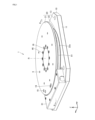
- FIG. 7 is a plan view showing table 20 and bearing 70.
- FIG. 8 is a cross-sectional perspective view of table 20 and bearing 70 shown in FIG.
- FIG. 9 shows the underside of table 20 .
- FIG. 9 is a plan view showing the table 20 and members fixed to the table 20.
- a scale 81 is printed on the entire circumference of the outer peripheral surface 22a of the shaft portion 22 of the table 20.
- printed means that a detection target portion that can be detected using a sensor is marked.
- a scale 81 is an aggregate of a large number of graduations 83 .
- the scale 81 is directly printed on the outer peripheral surface 22a.
- Direct printing means that the scale 83 is formed directly on the surface of the outer peripheral surface 22a without using a sticker, ribbon, or the like.
- the scale 83 is a minute concave portion (slit) formed in the outer peripheral surface 22a by laser processing or etching.
- the scale 83 may be a concave portion having a length of 0.2 mm to 10 mm and a depth of 0.1 to 100 ⁇ m and formed on the outer peripheral surface 22a.
- the interval between the scales 83 can be, for example, 1 to 100 ⁇ m.
- the scale 83 may be formed at equal intervals, or may have portions with different intervals.
- the scale 83 may be all the same over the entire circumference. Also, for example, as part of the scale 83 or in addition to the scale 83, a reference mark indicating the origin position or a specific position may be formed. Also, the length and width of the scale at regular intervals may be different from other scales so that they can be distinguished from other scales.
- the center of the table 20 is hollow.
- An inner peripheral surface 20 c of the table 20 is flush with the mounting portion 21 and the shaft portion 22 .
- the central portion of the table 20 is hollow and the scale 81 is directly provided on the outer peripheral surface 22a of the shaft portion 22, thereby making it possible to further reduce the weight of the rotating portion.
- a first annular portion 23 and a second annular portion 24, which are annular recesses extending along the circumferential direction of the table 20, are formed on the lower surface 20d of the table 20.
- a bearing 70 is arranged on the first annular portion 23 .
- Bearing 70 is arranged such that inner peripheral surface 23a defining first annular portion 23 and inner peripheral surface 72a of inner ring 72 of bearing 70 are in contact with each other.
- a magnet 51 is arranged on the second annular portion 24 .
- the thickness of the magnet 51 and the depth of the second annular portion 24 are approximately equal.
- the magnet 51 is substantially contained within the second annular portion 24 and slightly protrudes from the lower surface 20 d of the table 20 .
- magnet 51 is a plate-shaped magnet having a substantially trapezoidal surface that converges toward the center of rotation. Twenty-three magnets 51 arranged adjacent to each other form a magnet row 56 . The magnets 51 are arranged over the entire circumference of the second annular portion 24 .
- the magnet row 56 is an annular magnet row. In the magnet row 56, the magnets 51 are arranged so that the N poles and the S poles alternate. The number of magnets is not limited to this, and can be changed as appropriate according to the size and performance of the magnets, the required torque, and the like.
- the magnet 51 may be adhered to the table 20 with an adhesive, or may be fixed to the table 20 only by the magnetic force of the magnet 51 .
- the magnet row 56 is arranged to face the coil row 57 (FIG. 5).
- a motor 50 is composed of a magnet array 56 made up of magnets 51 and a coil array 57 made up of coils 52.
- the table 20 also serves as a magnet yoke that forms the magnetic path of the magnet 51 . Electric power is supplied to the coil 52 from connecting portions (not shown) corresponding to the three phases of U, V, and W through power lines (not shown).
- the substrate 14 is arranged between the magnet 51 and the coil 52 , so heat generated by the coil 52 during power supply is less likely to be transmitted to the magnet 51 .
- the rotary table device 1 does not have a ring scale arranged on the outer circumference of the shaft. Therefore, the outer peripheral surface 22a of the shaft portion 22 is exposed to the outside of the device, and the magnet 51 is also arranged at a position close to the outside of the device, so that the air cooling effect is further enhanced.
- the size of the rotary table device will be explained.
- the size of the rotary table device 1 is not particularly limited, the configuration in which the scale is directly printed on the outer peripheral surface of the table shaft portion provides an unprecedentedly small infinite rotary table device.
- the outer diameter of the table 20 is 100 mm and the size of the bed is 100 mm ⁇ 115 mm.
- the table is not limited to these sizes, and the outer diameter of the table can be about 10 to 1000.
- the size of the bed can be about 10 to 1020 mm on one side.
- Embodiment 2 of the rotary table device according to the present disclosure is shown. 10 to 12, rotating body 200 is a rotating portion that constitutes a rotary table apparatus according to a second embodiment of the present disclosure.
- the configuration of the rotary table device other than the rotating body 200 can be applied by changing the configuration of the rotary table device 1 described above as necessary.
- the main difference between the rotating body 200 and the table 20 according to the first embodiment is that the rotating body 200 is made of one part in which the table and the outer ring of the bearing are integrated. This difference will be mainly described.
- the same reference numerals are assigned to the same configurations as in the first embodiment, and the description thereof is omitted.
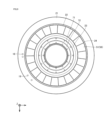
- FIG. 10 is a perspective view showing the rotating body 200 and the inner ring 720.
- FIG. 11 is a cross-sectional view showing a cross section cut along XI-XI in FIG. 10.
- FIG. 12 is a cross-sectional perspective view of the XI-XI section in FIG. 10, omitting the inner ring 720.
- FIG. 11 is a cross-sectional view showing a cross section cut along XI-XI in FIG. 10.
- FIG. 12 is a cross-sectional perspective view of the XI-XI section in FIG. 10, omitting the inner ring 720.
- rotating body 200 includes mounting portion 210 which is a hollow disc-shaped portion, shaft portion 220 positioned below mounting portion 210 and having a smaller outer diameter than mounting portion 210, including.
- the upper surface of the mounting portion 210 is formed flat.
- the mounting portion 210 and the shaft portion 220 are one piece that is integrally formed.
- a scale 810 is printed on the outer peripheral surface 220a of the shaft portion 220 over the entire circumference.
- the scale 810 includes a scale 830 formed directly on the surface of the outer peripheral surface 220a by laser processing, etching, or the like, like the scale 81 described above.
- raceway surfaces 710a and 710b which are rolling surfaces of the rolling elements 91 in the bearing 700, are formed on the inner peripheral surface 200c of the rotating body 200.
- the rotating body 200 is a member in which the table and the outer ring of the bearing in the rotary table device are integrally constructed.
- the rotating body 200 comprises a bearing outer ring 710 .
- the inner peripheral side of shaft portion 220 functions as outer ring 710 and constitutes bearing 700 together with inner ring 720 and rolling elements 91 .
- the rolling element 91 is a cylindrical roller.
- Bearing 700 is a cross roller bearing.
- the inner ring 720 is fixed to the bed (not shown) by screws (not shown) inserted through the threaded holes 160 .
- the lower surface 200d of the rotating body 200 is formed with a first annular portion 230, which is a concave portion of an annular portion extending in the circumferential direction of the rotating body 200. As shown in FIG. A plurality of plate-like magnets are arranged in the first annular portion 230 .
- Raceway surfaces 710a and 710b are formed on the inner peripheral surface 200c. In manufacturing, the raceway surfaces 710a and 710b and the outer peripheral surface 220a can be processed in one chuck, and can be manufactured in a rational manufacturing process.
- the rotary body 200 has a scale 810 printed directly on the outer peripheral surface of the shaft portion 220, and furthermore, the table and the outer ring of the bearing in the rotary table device are integrated. With these configurations, a smaller, infinitely rotatable rotary table device can be obtained through a rational manufacturing process.
- the outer ring 71 of the bearing 70 is fixed to the bed, and the inner ring 72 is fixed to the table 20 .
- the structure may be such that the outer ring of the bearing and the table are fixed, and the inner ring and the bed are fixed.
- Rotating body 200 is a member including outer ring 710 of bearing 700 .
- a structure in which the table and the inner ring of the bearing are integrated may be employed. These can be appropriately selected in consideration of the layout of parts, the size of the device, and the mass.
- 1 rotary table device 10 base portion, 11 bed, 12 support base, 14 substrate, 20 table, 21, 210 mounting portion, 22, 220 shaft portion, 23, 230 first circular ring portion, 24 second circular ring part, 35 gap, 41, 46, 47, 48 screw, 42 collar, 9, 13, 16, 17, 160 screw hole, 18, 19 mounting hole, 50 motor, 51 magnet, 52 coil, 53 first insulator, 56 magnet row, 57 coil row, 61 cover, 70, 700 bearing, 71, 710 outer ring, 72, 720 inner ring, 81, 810 scale, 82 encoder head, 83, 830 scale, 91 rolling element, 101 first concave portion, 102 First annular portion, 103 hole, 104 second annular portion, 105 second concave portion, 200 rotating body.
Landscapes
- Engineering & Computer Science (AREA)
- Power Engineering (AREA)
- General Engineering & Computer Science (AREA)
- Mechanical Engineering (AREA)
- Microelectronics & Electronic Packaging (AREA)
- Combustion & Propulsion (AREA)
- Chemical & Material Sciences (AREA)
- Electromagnetism (AREA)
- Physics & Mathematics (AREA)
- Machine Tool Units (AREA)
- Linear Motors (AREA)
- Rolling Contact Bearings (AREA)
- Permanent Magnet Type Synchronous Machine (AREA)
Priority Applications (4)
| Application Number | Priority Date | Filing Date | Title |
|---|---|---|---|
| IL311660A IL311660A (en) | 2021-09-24 | 2022-06-23 | rotating table |
| US18/693,177 US20240286850A1 (en) | 2021-09-24 | 2022-06-23 | Rotary table device |
| KR1020247009663A KR102843533B1 (ko) | 2021-09-24 | 2022-06-23 | 회전 테이블 장치 |
| CN202280056862.9A CN117837067A (zh) | 2021-09-24 | 2022-06-23 | 旋转工作台装置 |
Applications Claiming Priority (2)
| Application Number | Priority Date | Filing Date | Title |
|---|---|---|---|
| JP2021-155406 | 2021-09-24 | ||
| JP2021155406A JP7779689B2 (ja) | 2021-09-24 | 2021-09-24 | 回転テーブル装置 |
Publications (1)
| Publication Number | Publication Date |
|---|---|
| WO2023047733A1 true WO2023047733A1 (ja) | 2023-03-30 |
Family
ID=85720448
Family Applications (1)
| Application Number | Title | Priority Date | Filing Date |
|---|---|---|---|
| PCT/JP2022/025099 Ceased WO2023047733A1 (ja) | 2021-09-24 | 2022-06-23 | 回転テーブル装置 |
Country Status (7)
| Country | Link |
|---|---|
| US (1) | US20240286850A1 (enExample) |
| JP (1) | JP7779689B2 (enExample) |
| KR (1) | KR102843533B1 (enExample) |
| CN (1) | CN117837067A (enExample) |
| IL (1) | IL311660A (enExample) |
| TW (1) | TW202315287A (enExample) |
| WO (1) | WO2023047733A1 (enExample) |
Families Citing this family (1)
| Publication number | Priority date | Publication date | Assignee | Title |
|---|---|---|---|---|
| KR102810286B1 (ko) * | 2024-04-08 | 2025-05-26 | 주식회사 유닉스엔지니어링 | 중공 타입 회전 얼라인먼트 스테이지 |
Citations (3)
| Publication number | Priority date | Publication date | Assignee | Title |
|---|---|---|---|---|
| JP2004072960A (ja) * | 2002-08-09 | 2004-03-04 | Nippon Thompson Co Ltd | リニアモータを内蔵したアライメントステージ装置 |
| CN102364135A (zh) * | 2011-10-25 | 2012-02-29 | 洛阳Lyc轴承有限公司 | 一种ct机主轴轴承 |
| JP2020120430A (ja) * | 2019-01-18 | 2020-08-06 | 日本トムソン株式会社 | ロータリテーブル装置 |
Family Cites Families (2)
| Publication number | Priority date | Publication date | Assignee | Title |
|---|---|---|---|---|
| JPH0621374U (ja) * | 1992-03-02 | 1994-03-18 | シナノケンシ株式会社 | モータ |
| JP4543709B2 (ja) * | 2004-03-09 | 2010-09-15 | 株式会社エクォス・リサーチ | アキシャルギャップ回転電機 |
-
2021
- 2021-09-24 JP JP2021155406A patent/JP7779689B2/ja active Active
-
2022
- 2022-06-23 IL IL311660A patent/IL311660A/en unknown
- 2022-06-23 US US18/693,177 patent/US20240286850A1/en active Pending
- 2022-06-23 WO PCT/JP2022/025099 patent/WO2023047733A1/ja not_active Ceased
- 2022-06-23 KR KR1020247009663A patent/KR102843533B1/ko active Active
- 2022-06-23 CN CN202280056862.9A patent/CN117837067A/zh active Pending
- 2022-08-04 TW TW111129241A patent/TW202315287A/zh unknown
Patent Citations (3)
| Publication number | Priority date | Publication date | Assignee | Title |
|---|---|---|---|---|
| JP2004072960A (ja) * | 2002-08-09 | 2004-03-04 | Nippon Thompson Co Ltd | リニアモータを内蔵したアライメントステージ装置 |
| CN102364135A (zh) * | 2011-10-25 | 2012-02-29 | 洛阳Lyc轴承有限公司 | 一种ct机主轴轴承 |
| JP2020120430A (ja) * | 2019-01-18 | 2020-08-06 | 日本トムソン株式会社 | ロータリテーブル装置 |
Also Published As
| Publication number | Publication date |
|---|---|
| IL311660A (en) | 2024-05-01 |
| JP7779689B2 (ja) | 2025-12-03 |
| KR20240048544A (ko) | 2024-04-15 |
| JP2023046683A (ja) | 2023-04-05 |
| CN117837067A (zh) | 2024-04-05 |
| TW202315287A (zh) | 2023-04-01 |
| KR102843533B1 (ko) | 2025-08-07 |
| US20240286850A1 (en) | 2024-08-29 |
Similar Documents
| Publication | Publication Date | Title |
|---|---|---|
| JP3854244B2 (ja) | 永久磁石形モータ及びx線コンピュータ断層撮影装置 | |
| JP7705918B2 (ja) | ロータリテーブル装置 | |
| CN109792169B (zh) | 轴向间隙型电动机 | |
| US20100123362A1 (en) | Hydrostatic bearing pad type rotating device | |
| JP4608238B2 (ja) | アライメントステージ装置 | |
| WO2016017504A1 (ja) | ダイレクトドライブモータの製造方法、及び治具 | |
| WO2023047733A1 (ja) | 回転テーブル装置 | |
| US20070080597A1 (en) | Motor and manufacturing method thereof | |
| JP2000270514A (ja) | モータ、モータの製造方法、及び回転体装置 | |
| US20190265070A1 (en) | Rotational position detection device | |
| JP4584626B2 (ja) | アライメントステージ装置 | |
| JP7825117B2 (ja) | エンコーダおよびそれを備えたモータ | |
| JP2022084203A (ja) | 回転テーブル装置 | |
| JP4535814B2 (ja) | 静圧気体軸受スピンドルおよびその制御装置 | |
| JP2020162399A (ja) | ブラシレスモータ | |
| JP2002354778A (ja) | リニアモーター駆動によるロータリーテーブル装置 | |
| JPH05344701A (ja) | ブラシレスモータ | |
| JP2023072998A (ja) | 直動アクチュエータ | |
| JP2023046683A5 (enExample) | ||
| JPS61272613A (ja) | 磁気式ロ−タリエンコ−ダ | |
| JP2021122171A (ja) | ステッピングモータ | |
| JP2000295812A (ja) | モータ、モータの製造方法、及び回転体装置 | |
| JP2004120933A (ja) | ブラシレスモータ | |
| KR200190464Y1 (ko) | 브러시리스 dc모터 | |
| JPS6213724B2 (enExample) |
Legal Events
| Date | Code | Title | Description |
|---|---|---|---|
| 121 | Ep: the epo has been informed by wipo that ep was designated in this application |
Ref document number: 22872490 Country of ref document: EP Kind code of ref document: A1 |
|
| WWE | Wipo information: entry into national phase |
Ref document number: 202280056862.9 Country of ref document: CN |
|
| WWE | Wipo information: entry into national phase |
Ref document number: 18693177 Country of ref document: US |
|
| WWE | Wipo information: entry into national phase |
Ref document number: 311660 Country of ref document: IL |
|
| ENP | Entry into the national phase |
Ref document number: 20247009663 Country of ref document: KR Kind code of ref document: A |
|
| NENP | Non-entry into the national phase |
Ref country code: DE |
|
| WWE | Wipo information: entry into national phase |
Ref document number: 11202401751W Country of ref document: SG |
|
| 122 | Ep: pct application non-entry in european phase |
Ref document number: 22872490 Country of ref document: EP Kind code of ref document: A1 |