WO2023047733A1 - Rotary table device - Google Patents
Rotary table device Download PDFInfo
- Publication number
- WO2023047733A1 WO2023047733A1 PCT/JP2022/025099 JP2022025099W WO2023047733A1 WO 2023047733 A1 WO2023047733 A1 WO 2023047733A1 JP 2022025099 W JP2022025099 W JP 2022025099W WO 2023047733 A1 WO2023047733 A1 WO 2023047733A1
- Authority
- WO
- WIPO (PCT)
- Prior art keywords
- scale
- rotary table
- bearing
- table device
- peripheral surface
- Prior art date
Links
- 230000002093 peripheral effect Effects 0.000 claims description 40
- 238000000034 method Methods 0.000 description 7
- 238000004519 manufacturing process Methods 0.000 description 6
- 238000005096 rolling process Methods 0.000 description 6
- 239000000758 substrate Substances 0.000 description 6
- 239000012212 insulator Substances 0.000 description 4
- 230000000149 penetrating effect Effects 0.000 description 4
- 238000009434 installation Methods 0.000 description 3
- 230000008569 process Effects 0.000 description 3
- 238000012545 processing Methods 0.000 description 3
- 238000001816 cooling Methods 0.000 description 2
- 238000001514 detection method Methods 0.000 description 2
- 238000005530 etching Methods 0.000 description 2
- 238000003754 machining Methods 0.000 description 2
- 230000003287 optical effect Effects 0.000 description 2
- 238000007639 printing Methods 0.000 description 2
- 229910000831 Steel Inorganic materials 0.000 description 1
- 238000009825 accumulation Methods 0.000 description 1
- 239000000853 adhesive Substances 0.000 description 1
- 230000001070 adhesive effect Effects 0.000 description 1
- 238000003491 array Methods 0.000 description 1
- 238000010017 direct printing Methods 0.000 description 1
- 239000000428 dust Substances 0.000 description 1
- 230000000694 effects Effects 0.000 description 1
- 230000004907 flux Effects 0.000 description 1
- 230000006872 improvement Effects 0.000 description 1
- 238000011835 investigation Methods 0.000 description 1
- 238000012423 maintenance Methods 0.000 description 1
- 230000007246 mechanism Effects 0.000 description 1
- 238000012986 modification Methods 0.000 description 1
- 230000004048 modification Effects 0.000 description 1
- 239000010959 steel Substances 0.000 description 1
Images


Classifications
-
- F—MECHANICAL ENGINEERING; LIGHTING; HEATING; WEAPONS; BLASTING
- F16—ENGINEERING ELEMENTS AND UNITS; GENERAL MEASURES FOR PRODUCING AND MAINTAINING EFFECTIVE FUNCTIONING OF MACHINES OR INSTALLATIONS; THERMAL INSULATION IN GENERAL
- F16C—SHAFTS; FLEXIBLE SHAFTS; ELEMENTS OR CRANKSHAFT MECHANISMS; ROTARY BODIES OTHER THAN GEARING ELEMENTS; BEARINGS
- F16C19/00—Bearings with rolling contact, for exclusively rotary movement
- F16C19/22—Bearings with rolling contact, for exclusively rotary movement with bearing rollers essentially of the same size in one or more circular rows, e.g. needle bearings
- F16C19/34—Bearings with rolling contact, for exclusively rotary movement with bearing rollers essentially of the same size in one or more circular rows, e.g. needle bearings for both radial and axial load
- F16C19/36—Bearings with rolling contact, for exclusively rotary movement with bearing rollers essentially of the same size in one or more circular rows, e.g. needle bearings for both radial and axial load with a single row of rollers
-
- F—MECHANICAL ENGINEERING; LIGHTING; HEATING; WEAPONS; BLASTING
- F16—ENGINEERING ELEMENTS AND UNITS; GENERAL MEASURES FOR PRODUCING AND MAINTAINING EFFECTIVE FUNCTIONING OF MACHINES OR INSTALLATIONS; THERMAL INSULATION IN GENERAL
- F16C—SHAFTS; FLEXIBLE SHAFTS; ELEMENTS OR CRANKSHAFT MECHANISMS; ROTARY BODIES OTHER THAN GEARING ELEMENTS; BEARINGS
- F16C33/00—Parts of bearings; Special methods for making bearings or parts thereof
- F16C33/30—Parts of ball or roller bearings
- F16C33/58—Raceways; Race rings
-
- H—ELECTRICITY
- H02—GENERATION; CONVERSION OR DISTRIBUTION OF ELECTRIC POWER
- H02K—DYNAMO-ELECTRIC MACHINES
- H02K11/00—Structural association of dynamo-electric machines with electric components or with devices for shielding, monitoring or protection
- H02K11/20—Structural association of dynamo-electric machines with electric components or with devices for shielding, monitoring or protection for measuring, monitoring, testing, protecting or switching
- H02K11/21—Devices for sensing speed or position, or actuated thereby
- H02K11/22—Optical devices
-
- H—ELECTRICITY
- H02—GENERATION; CONVERSION OR DISTRIBUTION OF ELECTRIC POWER
- H02K—DYNAMO-ELECTRIC MACHINES
- H02K21/00—Synchronous motors having permanent magnets; Synchronous generators having permanent magnets
- H02K21/12—Synchronous motors having permanent magnets; Synchronous generators having permanent magnets with stationary armatures and rotating magnets
- H02K21/24—Synchronous motors having permanent magnets; Synchronous generators having permanent magnets with stationary armatures and rotating magnets with magnets axially facing the armatures, e.g. hub-type cycle dynamos
-
- H—ELECTRICITY
- H02—GENERATION; CONVERSION OR DISTRIBUTION OF ELECTRIC POWER
- H02K—DYNAMO-ELECTRIC MACHINES
- H02K41/00—Propulsion systems in which a rigid body is moved along a path due to dynamo-electric interaction between the body and a magnetic field travelling along the path
- H02K41/02—Linear motors; Sectional motors
- H02K41/03—Synchronous motors; Motors moving step by step; Reluctance motors
Definitions
- the present invention relates to a rotary table device.
- This application claims priority based on Japanese Patent Application No. 2021-155406 filed on September 24, 2021, and incorporates all the descriptions described in the Japanese Patent Application.
- a known rotary table device includes a fixed bed, a disk-shaped rotary table, and bearings arranged therebetween, and is rotationally driven by a linear motor.
- a linear motor is composed of an armature coil composed of a flat, annularly wound three-phase coreless coil, and a field magnet composed of a large number of plate-shaped magnets.
- a coil is fixed to the bed, a magnet is fixed to the rotary table, and the coil and the magnet are arranged so as to face each other.
- a tape-shaped scale is adhered to the outer peripheral surface of the table in a range corresponding to the rotation angle of the table. The position of the table is detected by reading the scale with an optical sensor placed on the bed.
- Patent Literature 2 discloses a rotary table device that infinitely rotates a table with respect to a bed.
- a ring-shaped scale is fitted to the shaft portion of the table.
- a ring member provided with a scale on the entire periphery is inserted into the outer peripheral side of the shaft portion of the table and fixed to the table by screws.
- JP-A-2004-72960 Japanese Patent Application Laid-Open No. 2020-120430
- a rotary table device that is compact, can be manufactured in a rational process, and has stable quality. Accordingly, it is an object of the present invention to provide a rotary table device that is small in size, can be manufactured in a rational process, and has stable quality.
- a rotary table device includes a base portion, a bearing, a table rotatably supported with respect to the base portion via the bearing, and rotating the table in a rotation direction of the bearing.
- a motor includes a plurality of flat, annularly wound three-phase coreless coils arranged side by side.
- a scale is printed on the outer peripheral surface of the table over the entire circumference.
- a sensor for reading the scale is provided on the base.
- a rotary table device that is small in size, can be manufactured in a rational process, and has stable quality is provided.
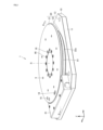
- FIG. 1 is a perspective view showing a rotary table device according to Embodiment 1.
- FIG. FIG. 2 is a cross-sectional view showing the rotary table device according to Embodiment 1.
- FIG. 3 is a partially enlarged sectional view showing the rotary table device according to Embodiment 1.
- FIG. 4 is a perspective view showing a bed of the rotary table device according to Embodiment 1.
- FIG. 5 is a plan view showing the bed of the rotary table device and members fixed to the bed according to the first embodiment.
- FIG. 6 is a perspective view showing the bed of the rotary table device and members fixed to the bed according to the first embodiment.
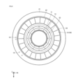
- 7 is a plan view showing a table of the rotary table device according to Embodiment 1.
- FIG. 1 is a perspective view showing a rotary table device according to Embodiment 1.
- FIG. FIG. 2 is a cross-sectional view showing the rotary table device according to Embodiment 1.
- FIG. 3 is a partially enlarged
- FIG. 8 is a cross-sectional perspective view showing a table of the rotary table device according to Embodiment 1.
- FIG. FIG. 9 is a plan view showing the table and the magnet row of the rotary table device according to Embodiment 1.
- FIG. 10 is a perspective view showing a rotor and a bearing according to Embodiment 2.
- FIG. 11 is a cross-sectional perspective view showing a rotating body and a bearing according to Embodiment 2.
- FIG. FIG. 12 is a cross-sectional perspective view showing a rotating body according to Embodiment 2.
- a rotary table device includes a base portion, a bearing, a table rotatably supported with respect to the base portion via the bearing, and rotating the table in a rotation direction of the bearing.
- a motor includes a plurality of flat, annularly wound three-phase coreless coils arranged side by side. a row of magnets arranged in a circumferential direction of the table with alternating magnetic poles and fixed to the table.
- a scale is printed on the outer peripheral surface of the table over the entire circumference.
- a sensor for reading the scale is provided on the base.
- a rotary table device that is used for the purpose of mounting a work of other parts on a table and rotating the work.
- a rotary table device driven by a direct drive servomotor is known.
- a rotary table device is known that reciprocates within a certain rotation angle range, such as 60° or 150°.
- An infinitely rotating table device that rotates 360° or more is also known. In either case, there is often provided a position detection mechanism that detects the position of the table by reading the graduations of a scale provided on the table with a sensor fixed to the base.
- the ring scale has a thickness of several mm to 10 mm in the radial direction. For this reason, especially in a small infinitely rotating table device, if a ring scale installation space is provided, the installation space for magnets and coil modules becomes relatively small, and a problem arises in that it is difficult to obtain sufficient torque. Under this circumstance, repeated investigations led to the idea of directly printing a scale on the entire circumference of the outer peripheral surface of the table.
- the rotary table device According to the rotary table device according to the present disclosure, it is possible to provide a rotary table device that does not require an installation space for a scale member, is compact, does not require attachment of a tape, and has stable quality through a rational manufacturing process. .
- a scale on the outer peripheral surface of the table, it is possible to reduce the number of parts, facilitate assembly, and reduce errors due to accumulation of part tolerances, resulting in excellent quality stability.
- the eccentricity of the rotating portion is suppressed, and precision maintenance and quality stability can be achieved.
- the coil array is a coil array in which a plurality of the coreless coils are arranged to form a part of a ring
- the magnet array is a circle in which the magnets are arranged along the entire circumference of the table. It may be an annular array of magnets.
- the table includes a disk-shaped mounting portion having a flat upper surface, and a shaft portion positioned below the mounting portion and having a diameter smaller than that of the mounting portion. may contain.
- the scale is printed on the outer peripheral surface of the shaft portion, and the encoder head including the sensor is disposed on the base portion so that the entire encoder head is positioned below the mounting portion.
- each of the graduations forming the scale may be a concave portion having a length of 0.2 mm to 10 mm and a depth of 0.1 to 100 ⁇ m and formed on the outer peripheral surface of the shaft portion.
- Such scale graduations can be produced by general-purpose manufacturing techniques such as laser processing, and sensor reading accuracy is sufficient.
- the table and the outer ring of the bearing may be configured as an integral part.
- the table and the outer ring of the bearing are constructed as an integral part, and the scale is printed on the outer peripheral surface of the table, the number of parts can be further reduced, and adjustment of assembly is unnecessary.
- machining of the raceway surface of the bearing outer ring and machining of the outer peripheral surface of the table can be performed in one chuck, and a high-precision rotary table device can be obtained through a rational manufacturing process.
- FIG. 1 is a schematic perspective view showing the structure of a rotary table device 1 according to Embodiment 1.
- the Z-axis direction is the direction in which the rotation axis (rotation axis of the bearing) R of the table of the rotary table device extends.
- FIG. 2 is a cross-sectional view of the rotary table device 1, showing a state cut along II-II in FIG.
- FIG. 3 is a cross-sectional view with some members omitted from FIG. 2 and partially enlarged.
- rotary table device 1 includes a base portion 10 that is a fixed portion, and a table 20 that is rotatable with respect to base portion 10 .
- the base section 10 includes a bed 11 .
- a cover 61 is fixed to the bed 11 .
- the cover 61 is a cover that covers the encoder head 82 (FIG. 2). The cover 61 ensures reading accuracy of the optical sensor of the encoder head 82 and prevents dust from entering the sensor portion.
- the table 20 is rotatable around the rotation axis R.
- the table 20 includes a mounting portion 21 which is a hollow disc-shaped portion and a shaft portion 22 positioned below the mounting portion 21 .
- the outer diameter of the shaft portion 22 is smaller than the outer diameter of the mounting portion 21 .
- the upper surface of the mounting portion 21 is formed flat.
- the mounting portion 21 and the shaft portion 22 are one component formed integrally.
- a scale 81 is printed on the outer peripheral surface 22a of the shaft portion 22 over the entire circumference.
- the mounting portion 21 is formed with a plurality of screw holes 9 penetrating the mounting portion 21 in the thickness direction (Z-axis direction).
- the screw hole 9 is used for attaching a work that is an external component.
- eight screw holes 9 are provided at equal intervals in the circumferential direction, but this number is not particularly limited.
- the mounting portion 21 is formed with a plurality of screw holes 16 penetrating through the mounting portion 21 in the thickness direction. A screw 46 is inserted into the screw hole 16 .
- the mounting portion 21 is provided with mounting holes 18 in which a reference mark for generating an origin signal can be mounted.
- Mounting portion 21 is also provided with mounting hole 19 for mounting a sensor dog for a sensor before origin or the like.
- the reference mark and the sensor before the origin are not essential components, so the mounting holes 18 and 19 may not be used. Moreover, the mounting holes 18 and 19 may not be provided in the mounting portion.
- the rotary table device 1 has bearings 70 .
- the bearing 70 is, for example, a cross roller bearing. In FIG. 2, the rolling elements of the bearing 70 are omitted.
- An outer ring 71 of bearing 70 is fixed to bed 11 .
- a screw 47 is inserted into the screw hole 17 penetrating from the lower surface of the bed 11 in the thickness direction.
- a screw 47 secures the bed 11 and the outer ring 71 .
- the inner ring 72 is fixed to the table 20 . Screws 46 secure table 20 and inner ring 72 . That is, the table 20 is rotatably supported with respect to the base portion 10 via the bearings 70 .
- a magnet 51 is attached to the bottom surface of the table 20 .
- a coil 52 that is a coreless coil is attached to the bed 11 at a position facing the magnet 51 .
- a plurality of magnets 51 are arranged in the circumferential direction of the table 20 to form a magnet row 56 (FIG. 9).
- a plurality of coils 52 are arranged at positions corresponding to the magnet arrays 56 to form a coil array 57 (FIG. 5).
- the support base 12 is fixed to the bed 11 with screws 48 .
- An encoder head 82 is fixed on the support base 12 .
- the encoder head 82 is arranged under the lower surface 21 b of the mounting portion 21 of the table 20 , which is a portion of the mounting portion 21 that protrudes outward from the shaft portion 22 .
- the encoder head 82 is covered with a cover 61 .
- the term “outward” means a direction away from the rotation axis R of the table 20. As shown in FIG.
- the bed 11 is provided with a first annular portion 102 having the same center as the rotation axis R (FIG. 2).
- the first annular portion 102 is relatively thicker than its surroundings.
- An outer peripheral surface 71 b of the outer ring 71 of the bearing 70 is in close contact with the inner peripheral surface 102 b of the first annular portion 102 .
- the outer ring 71 is spigot-fitted to the bed 11 .
- a scale 81 is printed on the outer peripheral surface 22 a of the shaft portion 22 of the table 20 .
- An encoder head 82 is provided facing the scale 81 .
- a gap 35 is formed between the scale 81 and the encoder head 82 so that the sensor of the encoder head 82 can read the scale graduations.
- the width of the gap 35 is substantially the same regardless of the overall size of the device and the layout of each part so that the scale graduations can be read.
- the size of the bed 11 can be approximately 65 mm to 75 mm ⁇ 75 mm to 85 mm.
- a rear surface 82 c of the encoder head 82 does not protrude outward from the outer peripheral surface 21 a of the mounting portion 21 .
- the encoder head 82 is accommodated under the placement section 21 .
- the rotary table device 1 does not have a ring scale, and a scale 81 is printed directly on the table. Therefore, the table and the sensor can be arranged close to each other. With this configuration, it is possible to make the rotary table apparatus compact. In addition, an improvement in sensor reading accuracy can be expected.
- the rotary table apparatus can be obtained in which the area of the mounting portion 21 is ensured and the overall structure is compact.
- FIG. 4 is a perspective view of the bed 11 forming the base 10.
- FIG. 5 is a plan view showing the bed 11 and members fixed to the bed 11.
- FIG. 6 is a perspective view showing the bed 11 and members fixed to the bed 11.
- the bed 11 is an integral member entirely made of steel. Approximately, the bed 11 has a hole 103 centered on the rotation axis R formed in its central portion. A first concave portion 101 , which is an annular concave portion, is formed concentrically with the hole 103 . A second recess 105 is formed continuously with the first recess 101 . The second recess 105 is a recess extending to the end face 11 e of the bed 11 .
- Four screw holes 13 are formed in the bed 11 so as to penetrate the bed 11 in the thickness direction (Z-axis direction). A screw hole 13 can be used to secure the bed 11 to an external member.
- the diameter of the hole 103 is approximately equal to the diameter of the inner peripheral surface of the outer ring 71 (FIG. 3) of the bearing 70.
- a plurality of screw holes 17 penetrating in the thickness direction (Z-axis direction) of the bed 11 are formed in the second annular portion 104 at regular intervals in the circumferential direction.
- the outer ring 71 ( FIG. 3 ) of the bearing 70 is spigot-fitted to the step formed by the inner peripheral surface 102 b of the first annular portion 102 and the upper surface 104 a of the second annular portion 104 .
- FIG. 5 shows part of the members fixed to the bed 11.
- first insulator 53 which is an insulating film corresponding to the shape of first recess 101 , is arranged on upper surface 101 a of first recess 101 .
- a coil 52 is arranged on the first insulator 53 .
- Each of the coils 52 is a flat, annularly wound coreless coil.
- Fifteen coils 52 constitute a coil array 57 forming a part of an annular ring.
- the coil 52 is a three-phase coil, and in the coil array 57, the U-phase, V-phase, and W-phase are repeatedly arranged in this order from one end.
- the coil array includes 15 coils in the first embodiment
- the number and arrangement of the coils included in the coil array can be changed according to the size of the motor and desired torque.
- an annular coil row arranged along the entire circumference of the first recess 101 may be formed.
- Coil 52 is fixed to bed 11 by screws 41 together with substrate 14 (FIG. 6) via collar 42 .
- a support base 12 and a cover 61 are fixed to the bed 11 .
- a central end surface 61b of the cover 61 is formed in an arcuate shape facing the outer peripheral surface 21a of the mounting portion 21 of the table 20 with a small gap therebetween.
- Components such as encoder signal lines and power lines are housed inside the cover 61 .
- FIG. 6 is a perspective view showing FIG. 5 with the substrate 14 added.
- the upper surface 14a of the substrate 14 is configured to be approximately the same height as the upper surface 11a of the bed 11 and the upper surface 102a of the first annular portion 102.
- An insulator such as an insulating film may be attached to the upper surface 14 a of the substrate 14 .
- FIG. 7 is a plan view showing table 20 and bearing 70.
- FIG. 8 is a cross-sectional perspective view of table 20 and bearing 70 shown in FIG.
- FIG. 9 shows the underside of table 20 .
- FIG. 9 is a plan view showing the table 20 and members fixed to the table 20.
- a scale 81 is printed on the entire circumference of the outer peripheral surface 22a of the shaft portion 22 of the table 20.
- printed means that a detection target portion that can be detected using a sensor is marked.
- a scale 81 is an aggregate of a large number of graduations 83 .
- the scale 81 is directly printed on the outer peripheral surface 22a.
- Direct printing means that the scale 83 is formed directly on the surface of the outer peripheral surface 22a without using a sticker, ribbon, or the like.
- the scale 83 is a minute concave portion (slit) formed in the outer peripheral surface 22a by laser processing or etching.
- the scale 83 may be a concave portion having a length of 0.2 mm to 10 mm and a depth of 0.1 to 100 ⁇ m and formed on the outer peripheral surface 22a.
- the interval between the scales 83 can be, for example, 1 to 100 ⁇ m.
- the scale 83 may be formed at equal intervals, or may have portions with different intervals.
- the scale 83 may be all the same over the entire circumference. Also, for example, as part of the scale 83 or in addition to the scale 83, a reference mark indicating the origin position or a specific position may be formed. Also, the length and width of the scale at regular intervals may be different from other scales so that they can be distinguished from other scales.
- the center of the table 20 is hollow.
- An inner peripheral surface 20 c of the table 20 is flush with the mounting portion 21 and the shaft portion 22 .
- the central portion of the table 20 is hollow and the scale 81 is directly provided on the outer peripheral surface 22a of the shaft portion 22, thereby making it possible to further reduce the weight of the rotating portion.
- a first annular portion 23 and a second annular portion 24, which are annular recesses extending along the circumferential direction of the table 20, are formed on the lower surface 20d of the table 20.
- a bearing 70 is arranged on the first annular portion 23 .
- Bearing 70 is arranged such that inner peripheral surface 23a defining first annular portion 23 and inner peripheral surface 72a of inner ring 72 of bearing 70 are in contact with each other.
- a magnet 51 is arranged on the second annular portion 24 .
- the thickness of the magnet 51 and the depth of the second annular portion 24 are approximately equal.
- the magnet 51 is substantially contained within the second annular portion 24 and slightly protrudes from the lower surface 20 d of the table 20 .
- magnet 51 is a plate-shaped magnet having a substantially trapezoidal surface that converges toward the center of rotation. Twenty-three magnets 51 arranged adjacent to each other form a magnet row 56 . The magnets 51 are arranged over the entire circumference of the second annular portion 24 .
- the magnet row 56 is an annular magnet row. In the magnet row 56, the magnets 51 are arranged so that the N poles and the S poles alternate. The number of magnets is not limited to this, and can be changed as appropriate according to the size and performance of the magnets, the required torque, and the like.
- the magnet 51 may be adhered to the table 20 with an adhesive, or may be fixed to the table 20 only by the magnetic force of the magnet 51 .
- the magnet row 56 is arranged to face the coil row 57 (FIG. 5).
- a motor 50 is composed of a magnet array 56 made up of magnets 51 and a coil array 57 made up of coils 52.
- the table 20 also serves as a magnet yoke that forms the magnetic path of the magnet 51 . Electric power is supplied to the coil 52 from connecting portions (not shown) corresponding to the three phases of U, V, and W through power lines (not shown).
- the substrate 14 is arranged between the magnet 51 and the coil 52 , so heat generated by the coil 52 during power supply is less likely to be transmitted to the magnet 51 .
- the rotary table device 1 does not have a ring scale arranged on the outer circumference of the shaft. Therefore, the outer peripheral surface 22a of the shaft portion 22 is exposed to the outside of the device, and the magnet 51 is also arranged at a position close to the outside of the device, so that the air cooling effect is further enhanced.
- the size of the rotary table device will be explained.
- the size of the rotary table device 1 is not particularly limited, the configuration in which the scale is directly printed on the outer peripheral surface of the table shaft portion provides an unprecedentedly small infinite rotary table device.
- the outer diameter of the table 20 is 100 mm and the size of the bed is 100 mm ⁇ 115 mm.
- the table is not limited to these sizes, and the outer diameter of the table can be about 10 to 1000.
- the size of the bed can be about 10 to 1020 mm on one side.
- Embodiment 2 of the rotary table device according to the present disclosure is shown. 10 to 12, rotating body 200 is a rotating portion that constitutes a rotary table apparatus according to a second embodiment of the present disclosure.
- the configuration of the rotary table device other than the rotating body 200 can be applied by changing the configuration of the rotary table device 1 described above as necessary.
- the main difference between the rotating body 200 and the table 20 according to the first embodiment is that the rotating body 200 is made of one part in which the table and the outer ring of the bearing are integrated. This difference will be mainly described.
- the same reference numerals are assigned to the same configurations as in the first embodiment, and the description thereof is omitted.
- FIG. 10 is a perspective view showing the rotating body 200 and the inner ring 720.
- FIG. 11 is a cross-sectional view showing a cross section cut along XI-XI in FIG. 10.
- FIG. 12 is a cross-sectional perspective view of the XI-XI section in FIG. 10, omitting the inner ring 720.
- FIG. 11 is a cross-sectional view showing a cross section cut along XI-XI in FIG. 10.
- FIG. 12 is a cross-sectional perspective view of the XI-XI section in FIG. 10, omitting the inner ring 720.
- rotating body 200 includes mounting portion 210 which is a hollow disc-shaped portion, shaft portion 220 positioned below mounting portion 210 and having a smaller outer diameter than mounting portion 210, including.
- the upper surface of the mounting portion 210 is formed flat.
- the mounting portion 210 and the shaft portion 220 are one piece that is integrally formed.
- a scale 810 is printed on the outer peripheral surface 220a of the shaft portion 220 over the entire circumference.
- the scale 810 includes a scale 830 formed directly on the surface of the outer peripheral surface 220a by laser processing, etching, or the like, like the scale 81 described above.
- raceway surfaces 710a and 710b which are rolling surfaces of the rolling elements 91 in the bearing 700, are formed on the inner peripheral surface 200c of the rotating body 200.
- the rotating body 200 is a member in which the table and the outer ring of the bearing in the rotary table device are integrally constructed.
- the rotating body 200 comprises a bearing outer ring 710 .
- the inner peripheral side of shaft portion 220 functions as outer ring 710 and constitutes bearing 700 together with inner ring 720 and rolling elements 91 .
- the rolling element 91 is a cylindrical roller.
- Bearing 700 is a cross roller bearing.
- the inner ring 720 is fixed to the bed (not shown) by screws (not shown) inserted through the threaded holes 160 .
- the lower surface 200d of the rotating body 200 is formed with a first annular portion 230, which is a concave portion of an annular portion extending in the circumferential direction of the rotating body 200. As shown in FIG. A plurality of plate-like magnets are arranged in the first annular portion 230 .
- Raceway surfaces 710a and 710b are formed on the inner peripheral surface 200c. In manufacturing, the raceway surfaces 710a and 710b and the outer peripheral surface 220a can be processed in one chuck, and can be manufactured in a rational manufacturing process.
- the rotary body 200 has a scale 810 printed directly on the outer peripheral surface of the shaft portion 220, and furthermore, the table and the outer ring of the bearing in the rotary table device are integrated. With these configurations, a smaller, infinitely rotatable rotary table device can be obtained through a rational manufacturing process.
- the outer ring 71 of the bearing 70 is fixed to the bed, and the inner ring 72 is fixed to the table 20 .
- the structure may be such that the outer ring of the bearing and the table are fixed, and the inner ring and the bed are fixed.
- Rotating body 200 is a member including outer ring 710 of bearing 700 .
- a structure in which the table and the inner ring of the bearing are integrated may be employed. These can be appropriately selected in consideration of the layout of parts, the size of the device, and the mass.
- 1 rotary table device 10 base portion, 11 bed, 12 support base, 14 substrate, 20 table, 21, 210 mounting portion, 22, 220 shaft portion, 23, 230 first circular ring portion, 24 second circular ring part, 35 gap, 41, 46, 47, 48 screw, 42 collar, 9, 13, 16, 17, 160 screw hole, 18, 19 mounting hole, 50 motor, 51 magnet, 52 coil, 53 first insulator, 56 magnet row, 57 coil row, 61 cover, 70, 700 bearing, 71, 710 outer ring, 72, 720 inner ring, 81, 810 scale, 82 encoder head, 83, 830 scale, 91 rolling element, 101 first concave portion, 102 First annular portion, 103 hole, 104 second annular portion, 105 second concave portion, 200 rotating body.
Abstract
A rotary table device according to the present disclosure comprises: a base part; a bearing; a table which is supported using the bearing so as to be able to rotate with respect to the base part; and a motor which rotates the table in the rotation direction of the bearing. The motor includes a coil row in which a plurality of three-phase coreless coils that are flat and annularly wound are arranged side by side and which is fixed to the base part, and a magnet row which is disposed so as to face the coil row, in which a plurality of plate-shaped magnets are arranged side by side in the circumferential direction of the table such that the opposite magnetic poles are alternated, and which is fixed to the table. A scale is printed along the entire outer circumferential surface of the table. A sensor for reading the scale is provided on the base part.
Description
本発明は、回転テーブル装置に関する。本出願は、2021年9月24日出願の日本国特許出願2021-155406号に基づく優先権を主張し、前記日本国特許出願に記載された全ての記載内容を援用する。
The present invention relates to a rotary table device. This application claims priority based on Japanese Patent Application No. 2021-155406 filed on September 24, 2021, and incorporates all the descriptions described in the Japanese Patent Application.
固定部であるベッドと、円盤状の回転テーブルと、それらの間に配置される軸受と、を備え、リニアモータによって回転駆動される回転テーブル装置が知られている。リニアモータは、扁平で環状に巻回された三相のコアレスコイルから成る電機子コイルと、多数の板状のマグネットから成る界磁マグネットと、から構成される。例えば特許文献1の回転テーブル装置では、ベッドにコイルが固定され、回転テーブルにマグネットが固定されており、コイルとマグネットとが対向するように配置されている。この回転テーブル装置では、テーブルの回転角に対応する範囲のテーブルの外周面に、テープ状のスケールが接着されている。ベッドに配置された光学センサがスケールを読み込むことによって、テーブルの位置が検出される。
A known rotary table device includes a fixed bed, a disk-shaped rotary table, and bearings arranged therebetween, and is rotationally driven by a linear motor. A linear motor is composed of an armature coil composed of a flat, annularly wound three-phase coreless coil, and a field magnet composed of a large number of plate-shaped magnets. For example, in the rotary table device of Patent Document 1, a coil is fixed to the bed, a magnet is fixed to the rotary table, and the coil and the magnet are arranged so as to face each other. In this rotary table device, a tape-shaped scale is adhered to the outer peripheral surface of the table in a range corresponding to the rotation angle of the table. The position of the table is detected by reading the scale with an optical sensor placed on the bed.
回転テーブル装置として、テーブルの回転が一定の回転角内に制限されず、360°あるいはそれ以上の角度で回転する無限回転テーブル装置が知られている。例えば特許文献2は、ベッドに対してテーブルを無限回転させる回転テーブル装置を開示している。特許文献2の回転テーブル装置では、テーブルの軸部にリング状のスケールを嵌め込むことが記載されている。全周にスケールが設けられたリング部材は、テーブルの軸部の外周側に挿入されるとともに、ねじによってテーブルに固定される。
As a rotary table device, an infinite rotary table device is known in which the rotation of the table is not restricted within a certain rotation angle, but rotates at an angle of 360° or more. For example, Patent Literature 2 discloses a rotary table device that infinitely rotates a table with respect to a bed. In the rotary table device of Patent Document 2, it is described that a ring-shaped scale is fitted to the shaft portion of the table. A ring member provided with a scale on the entire periphery is inserted into the outer peripheral side of the shaft portion of the table and fixed to the table by screws.
小型で、かつ、合理的な工程で製造できる、品質の安定した回転テーブル装置に対するニーズがある。そこで、小型で、かつ、合理的な工程で製造できる、品質の安定した回転テーブル装置を提供することを目的の1つとする。
There is a need for a rotary table device that is compact, can be manufactured in a rational process, and has stable quality. Accordingly, it is an object of the present invention to provide a rotary table device that is small in size, can be manufactured in a rational process, and has stable quality.
本開示に従った回転テーブル装置は、基台部と、軸受と、前記軸受を介して前記基台部に対して回転可能に支持されたテーブルと、前記テーブルを前記軸受の回転方向に回転させるモータと、を備える。前記モータは、扁平で環状に巻回された三相のコアレスコイルが複数並べて配置され、前記基台部に固定されたコイル列と、前記コイル列と対向して配置され、板状の複数の磁石が磁極を交互に異にして前記テーブルの周方向に並べて配置され、前記テーブルに固定された磁石列と、を含む。前記テーブルの外周面に、全周にわたってスケールが印字されている。前記スケールを読み取るためのセンサが、前記基台部に配設されている。
A rotary table device according to the present disclosure includes a base portion, a bearing, a table rotatably supported with respect to the base portion via the bearing, and rotating the table in a rotation direction of the bearing. a motor; The motor includes a plurality of flat, annularly wound three-phase coreless coils arranged side by side. a magnet row fixed to the table, in which magnets are arranged in a circumferential direction of the table with alternating magnetic poles. A scale is printed on the outer peripheral surface of the table over the entire circumference. A sensor for reading the scale is provided on the base.
上記回転テーブル装置によれば、小型で、かつ、合理的な工程で製造できる、品質の安定した回転テーブル装置が提供される。
According to the rotary table device described above, a rotary table device that is small in size, can be manufactured in a rational process, and has stable quality is provided.
[実施形態の概要]
最初に本開示の実施態様を列記して説明する。本開示に従った回転テーブル装置は、基台部と、軸受と、前記軸受を介して前記基台部に対して回転可能に支持されたテーブルと、前記テーブルを前記軸受の回転方向に回転させるモータと、を備える。前記モータは、扁平で環状に巻回された三相のコアレスコイルが複数並べて配置され、前記基台部に固定されたコイル列と、前記コイル列と対向して配設され、板状の複数の磁石が磁極を交互に異にして前記テーブルの周方向に並べて配置され、前記テーブルに固定された磁石列と、を含む。前記テーブルの外周面に、全周にわたってスケールが印字されている。前記スケールを読み取るためのセンサが、前記基台部に配設されている。 [Overview of embodiment]
First, the embodiments of the present disclosure are listed and described. A rotary table device according to the present disclosure includes a base portion, a bearing, a table rotatably supported with respect to the base portion via the bearing, and rotating the table in a rotation direction of the bearing. a motor; The motor includes a plurality of flat, annularly wound three-phase coreless coils arranged side by side. a row of magnets arranged in a circumferential direction of the table with alternating magnetic poles and fixed to the table. A scale is printed on the outer peripheral surface of the table over the entire circumference. A sensor for reading the scale is provided on the base.
従来、テーブルに他部品のワーク等を取り付け、ワークを回転させる目的で使用される回転テーブル装置が知られている。このような回転テーブル装置として、ダイレクトドライブサーボモータによって駆動される回転テーブル装置が知られている。例えば60°や150°等の一定の回転角の範囲内を往復運動する回転テーブル装置が知られている。また、360°以上回転する無限回転テーブル装置も知られている。いずれの場合も、基台に固定されたセンサがテーブルに設けられたスケールの目盛りを読み取ることによってテーブルの位置を検出する、位置検出機構が設けられていることが多い。
Conventionally, there has been known a rotary table device that is used for the purpose of mounting a work of other parts on a table and rotating the work. As such a rotary table device, a rotary table device driven by a direct drive servomotor is known. A rotary table device is known that reciprocates within a certain rotation angle range, such as 60° or 150°. An infinitely rotating table device that rotates 360° or more is also known. In either case, there is often provided a position detection mechanism that detects the position of the table by reading the graduations of a scale provided on the table with a sensor fixed to the base.
テーブルにスケールを取り付ける方法として、テーブルの外周面に目盛りが記されたテープを接着する方法、目盛りが記されたリング(リングスケール)をテーブルの外周に嵌める方法が知られている。ここで、無限回転テーブル装置では、テーブル外周面の全周にわたってスケールを設ける必要がある。テープ式スケールを無限回転テーブル装置に適用する場合、テーブル装置の1台ごとにテープを取り付ける垂直位置および水平位置、位相、原点位置等を精密に調整するため、工数とスキルが必要とされていた。また、テープのつなぎ目ができることが避けられなかった。このため、無限回転テーブル装置において、スケールが設けられたリングスケールをテーブルに取り付けることが提案されている(例えば特許文献2)。
Known methods for attaching a scale to a table include a method of adhering a tape marked with a scale to the outer circumference of the table, and a method of fitting a ring marked with a scale (ring scale) to the outer circumference of the table. Here, in the infinitely rotating table device, it is necessary to provide a scale over the entire circumference of the outer peripheral surface of the table. When applying a tape-type scale to an infinitely rotating table device, man-hours and skill were required to precisely adjust the vertical and horizontal positions, phase, origin position, etc. for attaching the tape to each table device. . In addition, it was inevitable that the seams of the tape would form. For this reason, it has been proposed to attach a ring scale provided with a scale to the table in an infinitely rotating table device (for example, Patent Document 2).
一方、リングスケールは径方向に数mmから10mm程度の厚みを有する。このため、特に小型の無限回転テーブル装置では、リングスケールの設置スペースを設けると、マグネットやコイルモジュールの設置スペースが相対的に小さくなり、十分なトルクを得ることが難しいという課題が生じた。この状況下で検討が重ねられ、テーブルの外周面の全周に直接スケールを印字することが想到された。
On the other hand, the ring scale has a thickness of several mm to 10 mm in the radial direction. For this reason, especially in a small infinitely rotating table device, if a ring scale installation space is provided, the installation space for magnets and coil modules becomes relatively small, and a problem arises in that it is difficult to obtain sufficient torque. Under this circumstance, repeated investigations led to the idea of directly printing a scale on the entire circumference of the outer peripheral surface of the table.
本開示にかかる回転テーブル装置によれば、スケール部材の設置スペースが不要で、小型でありながら、テープを取り付ける必要が無く、合理的な製造工程によって安定した品質を有する回転テーブル装置が提供される。また、テーブルの外周面にスケールを印字するという構成によって、部品点数の削減が可能であり、組み立てが容易になり、部品の公差の積み上げによる誤差が縮小されるため品質の安定性に優れる。また、スケール部材を用いないことにより、回転部分の偏心が抑制され、精度維持と品質安定が図られる。
According to the rotary table device according to the present disclosure, it is possible to provide a rotary table device that does not require an installation space for a scale member, is compact, does not require attachment of a tape, and has stable quality through a rational manufacturing process. . In addition, by printing a scale on the outer peripheral surface of the table, it is possible to reduce the number of parts, facilitate assembly, and reduce errors due to accumulation of part tolerances, resulting in excellent quality stability. Moreover, by not using a scale member, the eccentricity of the rotating portion is suppressed, and precision maintenance and quality stability can be achieved.
前記回転テーブル装置において、前記コイル列は、前記コアレスコイルが複数並べられて円環の一部をなすコイル列であり、前記磁石列は、前記磁石が前記テーブルの全周に並べて配置された円環状の磁石列であってよい。この構成によれば、回転角が一定範囲内に制限されない、無限回転テーブル装置が得られる。
In the rotary table device, the coil array is a coil array in which a plurality of the coreless coils are arranged to form a part of a ring, and the magnet array is a circle in which the magnets are arranged along the entire circumference of the table. It may be an annular array of magnets. With this configuration, it is possible to obtain an infinite rotary table device in which the rotation angle is not restricted within a certain range.
前記回転テーブル装置において、前記テーブルは、上面が平坦面に形成された円盤状の載置部と、前記載置部の下に位置し、前記載置部よりも小径である軸部と、を含んでよい。前記スケールは、前記軸部の外周面に印字されており、前記センサを含むエンコーダヘッドは、当該エンコーダヘッドの全体が前記載置部の下に位置するよう前記基台部上に配設されていてもよい。この構成によれば、テーブル載置部の大きさを確保しながらも、回転テーブル装置の全体を小型に構成できる。
In the rotary table device, the table includes a disk-shaped mounting portion having a flat upper surface, and a shaft portion positioned below the mounting portion and having a diameter smaller than that of the mounting portion. may contain. The scale is printed on the outer peripheral surface of the shaft portion, and the encoder head including the sensor is disposed on the base portion so that the entire encoder head is positioned below the mounting portion. may According to this configuration, the entire rotary table device can be configured to be small while ensuring the size of the table mounting portion.
前記回転テーブル装置において、前記スケールを構成する目盛りのそれぞれは、長さ0.2mm~10mm、深さ0.1~100μmであって前記軸部の外周面に形成された凹部であってよい。このようなスケール目盛りは、レーザ加工等の汎用的な製造技術によって作製可能であり、かつ、センサ読み取り精度は充分である。
In the rotary table device, each of the graduations forming the scale may be a concave portion having a length of 0.2 mm to 10 mm and a depth of 0.1 to 100 μm and formed on the outer peripheral surface of the shaft portion. Such scale graduations can be produced by general-purpose manufacturing techniques such as laser processing, and sensor reading accuracy is sufficient.
前記回転テーブル装置において、前記テーブルと、前記軸受の外輪とが一体の部品として構成されていてもよい。テーブルと軸受の外輪とが一体の部品として構成され、かつテーブルの外周面にスケールが印字されるという構成によれば、部品点数が一層削減され、組み付けの調整が不要となる。また、軸受外輪の軌道面の加工とテーブル外周面の加工をワンチャックで行うことが可能となり、合理的な製造工程によって高精度の回転テーブル装置が得られる。
In the rotary table device, the table and the outer ring of the bearing may be configured as an integral part. According to the structure in which the table and the outer ring of the bearing are constructed as an integral part, and the scale is printed on the outer peripheral surface of the table, the number of parts can be further reduced, and adjustment of assembly is unnecessary. In addition, machining of the raceway surface of the bearing outer ring and machining of the outer peripheral surface of the table can be performed in one chuck, and a high-precision rotary table device can be obtained through a rational manufacturing process.
[実施形態の具体例]
次に、本開示の回転テーブルの具体的な実施の形態の一例を、図面を参照しつつ説明する。以下の図面において同一または相当する部分には同一の参照番号を付しその説明は繰返さない。 [Specific example of embodiment]
Next, an example of specific embodiments of the rotary table of the present disclosure will be described with reference to the drawings. In the following drawings, the same or corresponding parts are given the same reference numerals, and the description thereof will not be repeated.
(実施の形態1)
図1は、実施の形態1における回転テーブル装置1の構造を示す概略斜視図である。図1において、Z軸方向は、回転テーブル装置のテーブルの回転軸(軸受の回転軸)Rが延びる方向である。図2は、回転テーブル装置1の断面図であり、図1中のII-IIで切断した状態を示す。図3は、図2からいくつかの部材を省略し、一部を拡大して示す断面図である。 (Embodiment 1)
FIG. 1 is a schematic perspective view showing the structure of a rotary table device 1 according to Embodiment 1. FIG. In FIG. 1, the Z-axis direction is the direction in which the rotation axis (rotation axis of the bearing) R of the table of the rotary table device extends. FIG. 2 is a cross-sectional view of the rotary table device 1, showing a state cut along II-II in FIG. FIG. 3 is a cross-sectional view with some members omitted from FIG. 2 and partially enlarged.
まず、回転テーブル装置1の概略的な構成を説明する。
図1を参照して、実施の形態1における回転テーブル装置1は、固定部である基台部10と、基台部10に対して回転可能であるテーブル20と、を備える。基台部10は、ベッド11を含む。ベッド11に、カバー61が固定されている。カバー61は、エンコーダヘッド82(図2)を覆うカバーである。カバー61によって、エンコーダヘッド82の光学センサの読み取り精度が確保され、また、センサ部分への埃の進入が防止される。 First, a schematic configuration of the rotary table device 1 will be described.
With reference to FIG. 1, rotary table device 1 according to Embodiment 1 includes abase portion 10 that is a fixed portion, and a table 20 that is rotatable with respect to base portion 10 . The base section 10 includes a bed 11 . A cover 61 is fixed to the bed 11 . The cover 61 is a cover that covers the encoder head 82 (FIG. 2). The cover 61 ensures reading accuracy of the optical sensor of the encoder head 82 and prevents dust from entering the sensor portion.
図1を参照して、実施の形態1における回転テーブル装置1は、固定部である基台部10と、基台部10に対して回転可能であるテーブル20と、を備える。基台部10は、ベッド11を含む。ベッド11に、カバー61が固定されている。カバー61は、エンコーダヘッド82(図2)を覆うカバーである。カバー61によって、エンコーダヘッド82の光学センサの読み取り精度が確保され、また、センサ部分への埃の進入が防止される。 First, a schematic configuration of the rotary table device 1 will be described.
With reference to FIG. 1, rotary table device 1 according to Embodiment 1 includes a
テーブル20は、回転軸Rを中心として回転可能である。テーブル20は、中空円盤状の部分である載置部21と、載置部21の下に位置する軸部22とを含む。軸部22の外径は、載置部21の外径よりも小さい。載置部21の上面は平坦に形成されている。載置部21および軸部22は、一体に形成された一部品である。軸部22の外周面22aに、全周にわたってスケール81が印字されている。
The table 20 is rotatable around the rotation axis R. The table 20 includes a mounting portion 21 which is a hollow disc-shaped portion and a shaft portion 22 positioned below the mounting portion 21 . The outer diameter of the shaft portion 22 is smaller than the outer diameter of the mounting portion 21 . The upper surface of the mounting portion 21 is formed flat. The mounting portion 21 and the shaft portion 22 are one component formed integrally. A scale 81 is printed on the outer peripheral surface 22a of the shaft portion 22 over the entire circumference.
載置部21には、載置部21を厚み方向(Z軸方向)に貫通する複数のねじ穴9が形成されている。ねじ穴9は、外部部品であるワークを取り付けるために利用される。回転テーブル装置1では、ねじ穴9が周方向に等間隔に8箇所設けられているが、この数は特に限定されない。また、載置部21には、載置部21を厚み方向に貫通する複数のねじ穴16が形成されている。ねじ穴16に、ねじ46が挿入されている。
The mounting portion 21 is formed with a plurality of screw holes 9 penetrating the mounting portion 21 in the thickness direction (Z-axis direction). The screw hole 9 is used for attaching a work that is an external component. In the rotary table device 1, eight screw holes 9 are provided at equal intervals in the circumferential direction, but this number is not particularly limited. Further, the mounting portion 21 is formed with a plurality of screw holes 16 penetrating through the mounting portion 21 in the thickness direction. A screw 46 is inserted into the screw hole 16 .
載置部21には、原点信号を生成するためのリファレンスマークを取り付けることができる、取り付け穴18が設けられている。また、載置部21には、原点前センサ等のためのセンサドグを取り付けることができる、取り付け穴19が設けられている。本開示の回転テーブル装置では、リファレンスマークおよび原点前センサは必須の構成ではないため、取り付け穴18,19は利用しなくてもよい。また、載置部に取り付け穴18,19が設けられていなくてもよい。
The mounting portion 21 is provided with mounting holes 18 in which a reference mark for generating an origin signal can be mounted. Mounting portion 21 is also provided with mounting hole 19 for mounting a sensor dog for a sensor before origin or the like. In the rotary table device of the present disclosure, the reference mark and the sensor before the origin are not essential components, so the mounting holes 18 and 19 may not be used. Moreover, the mounting holes 18 and 19 may not be provided in the mounting portion.
図2を参照して、回転テーブル装置1は軸受70を備える。軸受70は、例えばクロスローラベアリングである。図2では、軸受70の転動体は図示を省略されている。軸受70の外輪71は、ベッド11に固定されている。ベッド11の下面から厚み方向に貫通するねじ穴17にねじ47が挿入されている。ねじ47がベッド11と外輪71を固定している。内輪72は、テーブル20に固定されている。ねじ46が、テーブル20と内輪72を固定している。すなわち、テーブル20は、軸受70を介して、基台部10に対して回転可能に支持されている。
With reference to FIG. 2, the rotary table device 1 has bearings 70 . The bearing 70 is, for example, a cross roller bearing. In FIG. 2, the rolling elements of the bearing 70 are omitted. An outer ring 71 of bearing 70 is fixed to bed 11 . A screw 47 is inserted into the screw hole 17 penetrating from the lower surface of the bed 11 in the thickness direction. A screw 47 secures the bed 11 and the outer ring 71 . The inner ring 72 is fixed to the table 20 . Screws 46 secure table 20 and inner ring 72 . That is, the table 20 is rotatably supported with respect to the base portion 10 via the bearings 70 .
テーブル20の下面に、磁石51が取り付けられている。ベッド11における、磁石51と対向する位置に、コアレスコイルであるコイル52が取り付けられている。磁石51は、テーブル20の周方向に複数並べられて磁石列56を形成している(図9)。コイル52は、磁石列56に対応する位置に複数並べられて、コイル列57を形成している(図5)。コイル52に電流が流れると、磁石51とコイル52とから構成されるモータ50が機能してトルクが発生し、テーブル20が回転する。
A magnet 51 is attached to the bottom surface of the table 20 . A coil 52 that is a coreless coil is attached to the bed 11 at a position facing the magnet 51 . A plurality of magnets 51 are arranged in the circumferential direction of the table 20 to form a magnet row 56 (FIG. 9). A plurality of coils 52 are arranged at positions corresponding to the magnet arrays 56 to form a coil array 57 (FIG. 5). When a current flows through the coil 52, the motor 50 composed of the magnet 51 and the coil 52 functions to generate torque, and the table 20 rotates.
ベッド11には、支持台12がねじ48によって固定されている。支持台12上に、エンコーダヘッド82が固定されている。エンコーダヘッド82は、テーブル20の載置部21が軸部22よりも外方に張り出した部分である、載置部21の下面21bの下に、配置されている。エンコーダヘッド82は、カバー61でカバーされている。なお、ここで「外方」とは、テーブル20の回転軸Rから離れる方向を意味している。
The support base 12 is fixed to the bed 11 with screws 48 . An encoder head 82 is fixed on the support base 12 . The encoder head 82 is arranged under the lower surface 21 b of the mounting portion 21 of the table 20 , which is a portion of the mounting portion 21 that protrudes outward from the shaft portion 22 . The encoder head 82 is covered with a cover 61 . Here, the term “outward” means a direction away from the rotation axis R of the table 20. As shown in FIG.
図3を参照して、ベッド11には、回転軸R(図2)と中心を同じくする第1円環部102が設けられている。第1円環部102は、その周囲と比較して相対的に厚みの大きな部分である。軸受70の外輪71の外周面71bが、第1円環部102の内周面102bと密着している。外輪71は、ベッド11にインロー嵌合されている。
With reference to FIG. 3, the bed 11 is provided with a first annular portion 102 having the same center as the rotation axis R (FIG. 2). The first annular portion 102 is relatively thicker than its surroundings. An outer peripheral surface 71 b of the outer ring 71 of the bearing 70 is in close contact with the inner peripheral surface 102 b of the first annular portion 102 . The outer ring 71 is spigot-fitted to the bed 11 .
テーブル20の軸部22の外周面22aに、スケール81が印字されている。スケール81と対向して、エンコーダヘッド82が配設されている。スケール81とエンコーダヘッド82の間には、エンコーダヘッド82のセンサがスケール目盛りを読み取り可能である隙間35が形成されている。隙間35の幅は、スケール目盛りを読み取り可能とするため、装置全体の大きさや各部品の配置に関わらずほぼ同じである。例えば、テーブル20の載置部21の外径が65mmである回転テーブル装置では、ベッド11の大きさは65mm~75mm×75mm~85mm程度とできる。エンコーダヘッド82の背面82cは、載置部21の外周面21aから外方に突出していない。つまり、エンコーダヘッド82は、載置部21の下に収容されている。回転テーブル装置1は、リングスケールを備えず、テーブルに直接スケール81が印字されている。このため、テーブルとセンサを近接して配置できる。この構成によって、回転テーブル装置のコンパクト化が可能である。また、センサの読み取り精度の向上が期待できる。また、載置部21の下にエンコーダヘッド82を収容する構成によって、載置部21の面積を確保しながらも全体がコンパクトに構成された回転テーブル装置が得られる。
A scale 81 is printed on the outer peripheral surface 22 a of the shaft portion 22 of the table 20 . An encoder head 82 is provided facing the scale 81 . A gap 35 is formed between the scale 81 and the encoder head 82 so that the sensor of the encoder head 82 can read the scale graduations. The width of the gap 35 is substantially the same regardless of the overall size of the device and the layout of each part so that the scale graduations can be read. For example, in a rotary table device in which the mounting portion 21 of the table 20 has an outer diameter of 65 mm, the size of the bed 11 can be approximately 65 mm to 75 mm×75 mm to 85 mm. A rear surface 82 c of the encoder head 82 does not protrude outward from the outer peripheral surface 21 a of the mounting portion 21 . In other words, the encoder head 82 is accommodated under the placement section 21 . The rotary table device 1 does not have a ring scale, and a scale 81 is printed directly on the table. Therefore, the table and the sensor can be arranged close to each other. With this configuration, it is possible to make the rotary table apparatus compact. In addition, an improvement in sensor reading accuracy can be expected. In addition, with the configuration in which the encoder head 82 is accommodated under the mounting portion 21, the rotary table apparatus can be obtained in which the area of the mounting portion 21 is ensured and the overall structure is compact.
次に、回転テーブル装置における固定側である、回転テーブル装置1の基台部10および基台部10に固定される部材の詳細を説明する。図4は基台部10を構成するベッド11の斜視図である。図5は、ベッド11およびベッド11に固定される部材を示す平面図である。図6は、ベッド11およびベッド11に固定される部材を示す斜視図である。
Next, the details of the base portion 10 of the turntable device 1 and the members fixed to the base portion 10, which is the fixed side of the turntable device, will be described. FIG. 4 is a perspective view of the bed 11 forming the base 10. As shown in FIG. FIG. 5 is a plan view showing the bed 11 and members fixed to the bed 11. FIG. FIG. 6 is a perspective view showing the bed 11 and members fixed to the bed 11. FIG.
図4を参照して、ベッド11は全体が鋼板で構成された一体の部材である。大略的に、ベッド11は、中央部に、回転軸Rを中心とする穴103が形成されている。穴103と同心円状に、環状の凹部である第1凹部101が形成されている。第1凹部101と連続して、第2凹部105が形成されている。第2凹部105は、ベッド11の端面11eに至る凹部である。ベッド11を厚み方向(Z軸方向)に貫通するねじ穴13が、ベッド11の4箇所に形成されている。ねじ穴13を利用して、ベッド11を外部部材に固定できる。
With reference to FIG. 4, the bed 11 is an integral member entirely made of steel. Approximately, the bed 11 has a hole 103 centered on the rotation axis R formed in its central portion. A first concave portion 101 , which is an annular concave portion, is formed concentrically with the hole 103 . A second recess 105 is formed continuously with the first recess 101 . The second recess 105 is a recess extending to the end face 11 e of the bed 11 . Four screw holes 13 are formed in the bed 11 so as to penetrate the bed 11 in the thickness direction (Z-axis direction). A screw hole 13 can be used to secure the bed 11 to an external member.
穴103の径は、軸受70の外輪71(図3)の内周面の径とほぼ等しい。穴103の周縁に、第2円環部104がある。第2円環部104には、ベッド11の厚み方向(Z軸方向)に貫通するねじ穴17が周方向に等間隔に複数形成されている。第2円環部104の外側の周縁に沿って、第1円環部102がある。第1円環部102の内周面102bと、第2円環部104の上面104aとによって形成される段部に、軸受70の外輪71(図3)がインロー嵌合される。
The diameter of the hole 103 is approximately equal to the diameter of the inner peripheral surface of the outer ring 71 (FIG. 3) of the bearing 70. There is a second annular portion 104 on the periphery of the hole 103 . A plurality of screw holes 17 penetrating in the thickness direction (Z-axis direction) of the bed 11 are formed in the second annular portion 104 at regular intervals in the circumferential direction. Along the outer periphery of the second annular portion 104 is the first annular portion 102 . The outer ring 71 ( FIG. 3 ) of the bearing 70 is spigot-fitted to the step formed by the inner peripheral surface 102 b of the first annular portion 102 and the upper surface 104 a of the second annular portion 104 .
図5は、ベッド11に固定される部材の一部を示している。図5を参照して、第1凹部101の上面101aには、第1凹部101の形状に対応する絶縁フィルムである第1絶縁体53が配置されている。第1絶縁体53の上に、コイル52が配置される。コイル52はそれぞれ、扁平で環状に巻回されたコアレスコイルである。15個のコイル52が、円環の一部をなすコイル列57を構成している。コイル52は3相コイルであり、コイル列57においては、一方の端からU相、V相、W相の順に繰り返して配列されている。なお、実施の形態1においてコイル列には15個のコイルが含まれるが、コイル列に含まれるコイルの数や配置は、モータの大きさや所望のトルクに応じて変更できる。配設するコイル52を3つ増やして、第1凹部101の全周に並ぶ円環状のコイル列を形成してもよい。コイル52は、カラー42を介して、基板14(図6)とともに、ねじ41によってベッド11に固定されている。
FIG. 5 shows part of the members fixed to the bed 11. FIG. Referring to FIG. 5 , first insulator 53 , which is an insulating film corresponding to the shape of first recess 101 , is arranged on upper surface 101 a of first recess 101 . A coil 52 is arranged on the first insulator 53 . Each of the coils 52 is a flat, annularly wound coreless coil. Fifteen coils 52 constitute a coil array 57 forming a part of an annular ring. The coil 52 is a three-phase coil, and in the coil array 57, the U-phase, V-phase, and W-phase are repeatedly arranged in this order from one end. Although the coil array includes 15 coils in the first embodiment, the number and arrangement of the coils included in the coil array can be changed according to the size of the motor and desired torque. By increasing the number of coils 52 to be arranged by three, an annular coil row arranged along the entire circumference of the first recess 101 may be formed. Coil 52 is fixed to bed 11 by screws 41 together with substrate 14 (FIG. 6) via collar 42 .
ベッド11には、支持台12、カバー61が固定されている。カバー61の中央側の端面61bは、テーブル20の載置部21の外周面21aと僅かな隙間をあけて対向する弧状に形成されている。カバー61の内部に、エンコーダの信号線や電力線等の部品(不図示)が収容される。
A support base 12 and a cover 61 are fixed to the bed 11 . A central end surface 61b of the cover 61 is formed in an arcuate shape facing the outer peripheral surface 21a of the mounting portion 21 of the table 20 with a small gap therebetween. Components (not shown) such as encoder signal lines and power lines are housed inside the cover 61 .
図6は図5に基板14を付加して示す斜視図である。図6を参照して、基板14の上面14aは、ベッド11の上面11a、第1円環部102の上面102aとおおむね同じ高さになるよう構成されている。基板14の上面14aには、絶縁フィルム等の絶縁体が取り付けられていてもよい。
FIG. 6 is a perspective view showing FIG. 5 with the substrate 14 added. Referring to FIG. 6, the upper surface 14a of the substrate 14 is configured to be approximately the same height as the upper surface 11a of the bed 11 and the upper surface 102a of the first annular portion 102. As shown in FIG. An insulator such as an insulating film may be attached to the upper surface 14 a of the substrate 14 .
次に、回転テーブル装置における回転側である、回転テーブル装置1のテーブル20およびテーブル20に固定される部材の詳細を説明する。図7はテーブル20および軸受70を示す平面図である。図8は、図7に示すテーブル20および軸受70の断面斜視図である。図9は、テーブル20の下面を示す。図9は、テーブル20およびテーブル20に固定される部材を示す平面図である。
Next, the details of the table 20 of the rotary table device 1 and the members fixed to the table 20, which is the rotating side of the rotary table device, will be described. FIG. 7 is a plan view showing table 20 and bearing 70. FIG. 8 is a cross-sectional perspective view of table 20 and bearing 70 shown in FIG. FIG. 9 shows the underside of table 20 . FIG. 9 is a plan view showing the table 20 and members fixed to the table 20. FIG.
図7を参照して、テーブル20の軸部22の外周面22aの全周に、スケール81が印字されている。ここで、印字されているとは、センサを用いて検出可能な被検出部が印されていることを意味し、レーザ加工やエッチングによる刻印、印刷、転写、記入等によって作られるマークが形成されていることの全般を含む。スケール81は、多数の目盛り83の集合体である。スケール81は、外周面22aに直接印字されている。直接印字されているとは、シールやリボン等を介さず、外周面22aの表面に直接目盛り83が形成されていることを意味する。好ましくは、目盛り83はレーザ加工やエッチングで外周面22aに形成された微小な凹部(スリット)である。例えば、目盛り83は、長さ0.2mm~10mm、深さ0.1~100μmであって外周面22aに形成された凹部であってよい。目盛り83の間隔は、例えば、1~100μmとできる。目盛り83は等間隔に形成されていてもよく、間隔の異なる部分があってもよい。目盛り83は全周にわたってすべて同じでもよい。また、例えば、目盛り83の一部として、または、目盛り83に加えて、原点位置や特定の位置を示すリファレンスマークが形成されていてもよい。また、一定間隔ごとの目盛りの長さや幅が他の目盛りと異なるようにされていて、他の目盛りと区別可能であってもよい。
With reference to FIG. 7, a scale 81 is printed on the entire circumference of the outer peripheral surface 22a of the shaft portion 22 of the table 20. As shown in FIG. Here, "printed" means that a detection target portion that can be detected using a sensor is marked. including general A scale 81 is an aggregate of a large number of graduations 83 . The scale 81 is directly printed on the outer peripheral surface 22a. Direct printing means that the scale 83 is formed directly on the surface of the outer peripheral surface 22a without using a sticker, ribbon, or the like. Preferably, the scale 83 is a minute concave portion (slit) formed in the outer peripheral surface 22a by laser processing or etching. For example, the scale 83 may be a concave portion having a length of 0.2 mm to 10 mm and a depth of 0.1 to 100 μm and formed on the outer peripheral surface 22a. The interval between the scales 83 can be, for example, 1 to 100 μm. The scale 83 may be formed at equal intervals, or may have portions with different intervals. The scale 83 may be all the same over the entire circumference. Also, for example, as part of the scale 83 or in addition to the scale 83, a reference mark indicating the origin position or a specific position may be formed. Also, the length and width of the scale at regular intervals may be different from other scales so that they can be distinguished from other scales.
図8を参照して、テーブル20の中心部は中空である。テーブル20の内周面20cは、載置部21と軸部22とにわたって面一である。テーブル20の中心部を中空とし、かつスケール81を軸部22の外周面22aに直接設ける構成によって、回転部分をより軽量化できる。テーブル20の下面20dには、テーブル20の周方向に沿って延在する円環状の凹部である、第1円環部23および第2円環部24が形成されている。第1円環部23に、軸受70が配置される。第1円環部23を規定する内周面23aと軸受70の内輪72の内周面72aとが接するように、軸受70が配置されている。第2円環部24に、磁石51が配置される。磁石51の厚みと、第2円環部24の深さはおおむね等しい。磁石51は第2円環部24内にほぼ収められ、テーブル20の下面20dからの突出はわずかである。
With reference to FIG. 8, the center of the table 20 is hollow. An inner peripheral surface 20 c of the table 20 is flush with the mounting portion 21 and the shaft portion 22 . The central portion of the table 20 is hollow and the scale 81 is directly provided on the outer peripheral surface 22a of the shaft portion 22, thereby making it possible to further reduce the weight of the rotating portion. A first annular portion 23 and a second annular portion 24, which are annular recesses extending along the circumferential direction of the table 20, are formed on the lower surface 20d of the table 20. As shown in FIG. A bearing 70 is arranged on the first annular portion 23 . Bearing 70 is arranged such that inner peripheral surface 23a defining first annular portion 23 and inner peripheral surface 72a of inner ring 72 of bearing 70 are in contact with each other. A magnet 51 is arranged on the second annular portion 24 . The thickness of the magnet 51 and the depth of the second annular portion 24 are approximately equal. The magnet 51 is substantially contained within the second annular portion 24 and slightly protrudes from the lower surface 20 d of the table 20 .
図9を参照して、磁石51は、回転中心に向かって収束する略台形状の面を有する板状の磁石である。互いに隣接して配置された23個の磁石51が、磁石列56を構成している。磁石51は第2円環部24の全周にわたって配置されている。磁石列56は円環状の磁石列である。磁石列56において、磁石51はN極とS極が交互になるように配置されている。なお、磁石の個数は配列の形態はこれに制限されず、磁石のサイズや性能、要求されるトルク等に応じて適宜変更できる。磁石51は例えば、接着剤によってテーブル20に接着されていてもよいし、磁石51の磁力のみでテーブル20に固定されていてもよい。磁石列56は、コイル列57(図5)に対向するよう配置されている。
Referring to FIG. 9, magnet 51 is a plate-shaped magnet having a substantially trapezoidal surface that converges toward the center of rotation. Twenty-three magnets 51 arranged adjacent to each other form a magnet row 56 . The magnets 51 are arranged over the entire circumference of the second annular portion 24 . The magnet row 56 is an annular magnet row. In the magnet row 56, the magnets 51 are arranged so that the N poles and the S poles alternate. The number of magnets is not limited to this, and can be changed as appropriate according to the size and performance of the magnets, the required torque, and the like. For example, the magnet 51 may be adhered to the table 20 with an adhesive, or may be fixed to the table 20 only by the magnetic force of the magnet 51 . The magnet row 56 is arranged to face the coil row 57 (FIG. 5).
次に、回転テーブル装置1のモータ50について説明する。
図2、図5、図9を参照して、磁石51で構成される磁石列56と、コイル52で構成されるコイル列57とが、モータ50を構成する。テーブル20は、磁石51の磁路を形成するマグネットヨークを兼ねている。コイル52に、U,V,Wの3相のそれぞれに対応する接続部(不図示)から、電力線(不図示)を通じて、電力が供給される。回転テーブル装置1では、基板14が磁石51とコイル52との間に配置されており、給電時にコイル52で発生する熱が磁石51に伝わりにくい。この構成によって、磁石51の温度上昇による磁束密度の低下が低減され、モータ50の出力低下を抑制できる。さらに、テーブル20の回転に伴う気流によって、磁石51の空冷が期待できる。回転テーブル装置1は、軸部の外周に配置されるリングスケールを有さない。このため、軸部22の外周面22aが機器外部に露出し、磁石51も機器外部に近い位置に配置されるため、空冷効果がより高くなる。 Next, themotor 50 of the rotary table device 1 will be described.
2, 5 and 9, amotor 50 is composed of a magnet array 56 made up of magnets 51 and a coil array 57 made up of coils 52. As shown in FIG. The table 20 also serves as a magnet yoke that forms the magnetic path of the magnet 51 . Electric power is supplied to the coil 52 from connecting portions (not shown) corresponding to the three phases of U, V, and W through power lines (not shown). In the rotary table device 1 , the substrate 14 is arranged between the magnet 51 and the coil 52 , so heat generated by the coil 52 during power supply is less likely to be transmitted to the magnet 51 . With this configuration, the decrease in the magnetic flux density due to the temperature rise of the magnet 51 can be reduced, and the decrease in the output of the motor 50 can be suppressed. Furthermore, air cooling of the magnets 51 can be expected due to the air current accompanying the rotation of the table 20 . The rotary table device 1 does not have a ring scale arranged on the outer circumference of the shaft. Therefore, the outer peripheral surface 22a of the shaft portion 22 is exposed to the outside of the device, and the magnet 51 is also arranged at a position close to the outside of the device, so that the air cooling effect is further enhanced.
図2、図5、図9を参照して、磁石51で構成される磁石列56と、コイル52で構成されるコイル列57とが、モータ50を構成する。テーブル20は、磁石51の磁路を形成するマグネットヨークを兼ねている。コイル52に、U,V,Wの3相のそれぞれに対応する接続部(不図示)から、電力線(不図示)を通じて、電力が供給される。回転テーブル装置1では、基板14が磁石51とコイル52との間に配置されており、給電時にコイル52で発生する熱が磁石51に伝わりにくい。この構成によって、磁石51の温度上昇による磁束密度の低下が低減され、モータ50の出力低下を抑制できる。さらに、テーブル20の回転に伴う気流によって、磁石51の空冷が期待できる。回転テーブル装置1は、軸部の外周に配置されるリングスケールを有さない。このため、軸部22の外周面22aが機器外部に露出し、磁石51も機器外部に近い位置に配置されるため、空冷効果がより高くなる。 Next, the
2, 5 and 9, a
ここで、回転テーブル装置の大きさを説明する。回転テーブル装置1の大きさは特に制限されないが、テーブル軸部の外周面に直接スケールを印字する構成によって、従来になく小型の無限回転テーブル装置が得られる。例えば、テーブル20の外径が100mm、ベッドの大きさが100mm×115mmである、無限回転テーブル装置を構成できる。当然ながら、これらの大きさに限定されるものではなく、テーブルの外径は10~1000程度とできる。ベッドの大きさは、1辺が10~1020mm程度とできる。
Here, the size of the rotary table device will be explained. Although the size of the rotary table device 1 is not particularly limited, the configuration in which the scale is directly printed on the outer peripheral surface of the table shaft portion provides an unprecedentedly small infinite rotary table device. For example, it is possible to construct an infinitely rotating table device in which the outer diameter of the table 20 is 100 mm and the size of the bed is 100 mm×115 mm. Of course, the table is not limited to these sizes, and the outer diameter of the table can be about 10 to 1000. The size of the bed can be about 10 to 1020 mm on one side.
(実施の形態2)
本開示にかかる回転テーブル装置の実施の形態2を示す。図10~図12を参照して、回転体200は、本開示に従う実施の形態2である回転テーブル装置を構成する回転部である。回転体200以外の回転テーブル装置の構成は、上述の回転テーブル装置1の構成を必要に応じて変更して適用可能である。回転体200は、テーブルと軸受の外輪とが一体化された一部品でなる点が、実施の形態1におけるテーブル20との主な相違点である。この相違点を中心に説明する。実施の形態1と同じ構成には同一の符号を付し、説明を省略する。 (Embodiment 2)
Embodiment 2 of the rotary table device according to the present disclosure is shown. 10 to 12, rotatingbody 200 is a rotating portion that constitutes a rotary table apparatus according to a second embodiment of the present disclosure. The configuration of the rotary table device other than the rotating body 200 can be applied by changing the configuration of the rotary table device 1 described above as necessary. The main difference between the rotating body 200 and the table 20 according to the first embodiment is that the rotating body 200 is made of one part in which the table and the outer ring of the bearing are integrated. This difference will be mainly described. The same reference numerals are assigned to the same configurations as in the first embodiment, and the description thereof is omitted.
本開示にかかる回転テーブル装置の実施の形態2を示す。図10~図12を参照して、回転体200は、本開示に従う実施の形態2である回転テーブル装置を構成する回転部である。回転体200以外の回転テーブル装置の構成は、上述の回転テーブル装置1の構成を必要に応じて変更して適用可能である。回転体200は、テーブルと軸受の外輪とが一体化された一部品でなる点が、実施の形態1におけるテーブル20との主な相違点である。この相違点を中心に説明する。実施の形態1と同じ構成には同一の符号を付し、説明を省略する。 (Embodiment 2)
Embodiment 2 of the rotary table device according to the present disclosure is shown. 10 to 12, rotating
図10は、回転体200および内輪720を示す斜視図である。図11は、図10におけるXI-XIで切断する断面を示す断面図である。図12は、図10におけるXI-XI断面の断面斜視図であり、内輪720を省いて示す図である。
10 is a perspective view showing the rotating body 200 and the inner ring 720. FIG. 11 is a cross-sectional view showing a cross section cut along XI-XI in FIG. 10. FIG. 12 is a cross-sectional perspective view of the XI-XI section in FIG. 10, omitting the inner ring 720. FIG.
図10を参照して、回転体200は、中空円盤状の部分である載置部210と、載置部210の下に位置し、載置部210よりも外径の小さな軸部220と、を含む。載置部210の上面は平坦に形成されている。載置部210および軸部220は、一体に形成された一部品である。軸部220の外周面220aに、全周にわたってスケール810が印字されている。スケール810は、前述のスケール81と同様にレーザ加工やエッチング等によって外周面220aの表面上に直接形成された、目盛り830から構成される。
Referring to FIG. 10, rotating body 200 includes mounting portion 210 which is a hollow disc-shaped portion, shaft portion 220 positioned below mounting portion 210 and having a smaller outer diameter than mounting portion 210, including. The upper surface of the mounting portion 210 is formed flat. The mounting portion 210 and the shaft portion 220 are one piece that is integrally formed. A scale 810 is printed on the outer peripheral surface 220a of the shaft portion 220 over the entire circumference. The scale 810 includes a scale 830 formed directly on the surface of the outer peripheral surface 220a by laser processing, etching, or the like, like the scale 81 described above.
図11を参照して、回転体200の内周面200cに、軸受700における転動体91の転走面である軌道面710a、710bが形成されている。すなわち、回転体200は、回転テーブル装置におけるテーブルと軸受の外輪とが一体に構成されてなる部材である。回転体200は、軸受の外輪710を含んでなる。軸部220の内周側が外輪710として機能し、内輪720、転動体91とともに軸受700を構成する。転動体91は円柱状のローラである。軸受700はクロスローラベアリングである。内輪720は、ねじ穴160に挿入されるねじ(不図示)によってベッド(不図示)に固定される。
11, raceway surfaces 710a and 710b, which are rolling surfaces of the rolling elements 91 in the bearing 700, are formed on the inner peripheral surface 200c of the rotating body 200. As shown in FIG. That is, the rotating body 200 is a member in which the table and the outer ring of the bearing in the rotary table device are integrally constructed. The rotating body 200 comprises a bearing outer ring 710 . The inner peripheral side of shaft portion 220 functions as outer ring 710 and constitutes bearing 700 together with inner ring 720 and rolling elements 91 . The rolling element 91 is a cylindrical roller. Bearing 700 is a cross roller bearing. The inner ring 720 is fixed to the bed (not shown) by screws (not shown) inserted through the threaded holes 160 .
図11、図12を参照して、回転体200の下面200dには、回転体200の周方向に延在する円環状部の凹部である第1円環部230が形成されている。第1円環部230には、複数の板状の磁石が配列される。内周面200cには軌道面710a、710bが形成されている。製造において、軌道面710a、710bと、外周面220aはワンチャックで加工することが可能であり、合理的な製造工程で製造可能である。
11 and 12, the lower surface 200d of the rotating body 200 is formed with a first annular portion 230, which is a concave portion of an annular portion extending in the circumferential direction of the rotating body 200. As shown in FIG. A plurality of plate-like magnets are arranged in the first annular portion 230 . Raceway surfaces 710a and 710b are formed on the inner peripheral surface 200c. In manufacturing, the raceway surfaces 710a and 710b and the outer peripheral surface 220a can be processed in one chuck, and can be manufactured in a rational manufacturing process.
回転体200は、スケール810が軸部220の外周面に直接印字されており、さらに、回転テーブル装置におけるテーブルと軸受の外輪とが一体化されている。これらの構成によって、より小型で、無限回転可能な回転テーブル装置を合理的な製造工程によって得ることができる。
The rotary body 200 has a scale 810 printed directly on the outer peripheral surface of the shaft portion 220, and furthermore, the table and the outer ring of the bearing in the rotary table device are integrated. With these configurations, a smaller, infinitely rotatable rotary table device can be obtained through a rational manufacturing process.
(その他の変形例)
回転テーブル装置1では、軸受70の外輪71がベッドに固定され、内輪72がテーブル20に固定されている。これに対して、軸受の外輪とテーブルが固定され、内輪とベッドが固定される構造としてもよい。また、回転体200は軸受700の外輪710を含む部材である。これに対して、テーブルと軸受の内輪が一体化される構造としてもよい。これらは、部品のレイアウト、装置の大きさ、質量を考慮して適切に選択されうる。 (Other modifications)
In the rotary table device 1 , theouter ring 71 of the bearing 70 is fixed to the bed, and the inner ring 72 is fixed to the table 20 . Alternatively, the structure may be such that the outer ring of the bearing and the table are fixed, and the inner ring and the bed are fixed. Rotating body 200 is a member including outer ring 710 of bearing 700 . Alternatively, a structure in which the table and the inner ring of the bearing are integrated may be employed. These can be appropriately selected in consideration of the layout of parts, the size of the device, and the mass.
回転テーブル装置1では、軸受70の外輪71がベッドに固定され、内輪72がテーブル20に固定されている。これに対して、軸受の外輪とテーブルが固定され、内輪とベッドが固定される構造としてもよい。また、回転体200は軸受700の外輪710を含む部材である。これに対して、テーブルと軸受の内輪が一体化される構造としてもよい。これらは、部品のレイアウト、装置の大きさ、質量を考慮して適切に選択されうる。 (Other modifications)
In the rotary table device 1 , the
今回開示された実施の形態はすべての点で例示であって、どのような面からも制限的なものではないと理解されるべきである。本発明の範囲は上記した説明ではなく、請求の範囲によって規定され、請求の範囲と均等の意味および範囲内でのすべての変更が含まれることが意図される。
It should be understood that the embodiments disclosed this time are illustrative in all respects and not restrictive in any aspect. The scope of the present invention is defined by the scope of the claims rather than the above description, and is intended to include all changes within the meaning and scope of equivalence to the scope of the claims.
1 回転テーブル装置、10 基台部、11 ベッド、12 支持台、14 基板、20 テーブル、21、210 載置部、22、220 軸部、23、230 第1円環部、24 第2円環部、35 隙間、41、46、47、48 ねじ、42 カラー、9、13、16、17、160 ねじ穴、18、19 取り付け穴、50 モータ、51 磁石、52 コイル、53 第1絶縁体、56 磁石列、57 コイル列、61 カバー、70、700 軸受、71、710 外輪、72、720 内輪、81、810 スケール、82 エンコーダヘッド、83、830 目盛り、91 転動体、101 第1凹部、102 第1円環部、103 穴、104 第2円環部、105 第2凹部、200 回転体。
1 rotary table device, 10 base portion, 11 bed, 12 support base, 14 substrate, 20 table, 21, 210 mounting portion, 22, 220 shaft portion, 23, 230 first circular ring portion, 24 second circular ring part, 35 gap, 41, 46, 47, 48 screw, 42 collar, 9, 13, 16, 17, 160 screw hole, 18, 19 mounting hole, 50 motor, 51 magnet, 52 coil, 53 first insulator, 56 magnet row, 57 coil row, 61 cover, 70, 700 bearing, 71, 710 outer ring, 72, 720 inner ring, 81, 810 scale, 82 encoder head, 83, 830 scale, 91 rolling element, 101 first concave portion, 102 First annular portion, 103 hole, 104 second annular portion, 105 second concave portion, 200 rotating body.
Claims (5)
- 基台部と、
軸受と、
前記軸受を介して前記基台部に対して回転可能に支持されたテーブルと、
前記テーブルを前記軸受の回転方向に回転させるモータと、を備え、
前記モータは、
扁平で環状に巻回された三相のコアレスコイルが複数並べて配置され、前記基台部に固定されたコイル列と、
前記コイル列と対向して配置され、板状の複数の磁石が磁極を交互に異にして前記テーブルの周方向に並べて配置され、前記テーブルに固定された磁石列と、
を含み、
前記テーブルの外周面に全周にわたってスケールが印字されており、
前記スケールを読み取るためのセンサが前記基台部に配設されている、
回転テーブル装置。 a base;
a bearing;
a table rotatably supported with respect to the base via the bearing;
a motor that rotates the table in the rotation direction of the bearing,
The motor is
a coil array in which a plurality of flat, annularly wound three-phase coreless coils are arranged side by side and fixed to the base;
a magnet row arranged facing the coil row, a plurality of plate-shaped magnets arranged in a circumferential direction of the table with alternately different magnetic poles, and fixed to the table;
including
A scale is printed on the outer peripheral surface of the table over the entire circumference,
a sensor for reading the scale is disposed on the base;
rotary table device. - 前記コイル列は前記コアレスコイルが複数並べられて円環の一部をなすコイル列であり、
前記磁石列は前記磁石が前記テーブルの全周に並べて配置された円環状の磁石列である、
請求項1に記載の回転テーブル装置。 The coil array is a coil array in which a plurality of the coreless coils are arranged to form a part of an annular ring,
The magnet array is an annular magnet array in which the magnets are arranged along the entire circumference of the table,
2. The rotary table apparatus according to claim 1. - 前記テーブルは、
上面が平坦面に形成された円盤状の載置部と、
前記載置部の下に位置し、前記載置部よりも小径である軸部と、を含み、
前記スケールは、前記軸部の外周面に印字されており、
前記センサを含むエンコーダヘッドは、当該エンコーダヘッドの全体が前記載置部の下に位置するよう前記基台部上に配設されている、
請求項1または請求項2に記載の回転テーブル装置。 The table is
a disk-shaped mounting portion having a flat upper surface;
a shaft portion positioned below the mounting portion and having a diameter smaller than that of the mounting portion;
The scale is printed on the outer peripheral surface of the shaft,
The encoder head including the sensor is disposed on the base portion so that the entire encoder head is positioned under the mounting portion.
3. The rotary table device according to claim 1 or 2. - 前記スケールを構成する目盛りのそれぞれは、長さ0.2mm~10mm、深さ0.1~100μmであって前記軸部の外周面に形成された凹部である、
請求項1または請求項2に記載の回転テーブル装置。 Each of the graduations constituting the scale is a concave portion having a length of 0.2 mm to 10 mm and a depth of 0.1 to 100 μm and formed on the outer peripheral surface of the shaft portion.
3. The rotary table device according to claim 1 or 2. - 前記テーブルと、前記軸受の外輪とが一体の部品として構成されている、
請求項1または請求項2に記載の回転テーブル装置。 The table and the outer ring of the bearing are configured as an integral part,
3. The rotary table device according to claim 1 or 2.
Priority Applications (1)
| Application Number | Priority Date | Filing Date | Title |
|---|---|---|---|
| CN202280056862.9A CN117837067A (en) | 2021-09-24 | 2022-06-23 | Rotary table device |
Applications Claiming Priority (2)
| Application Number | Priority Date | Filing Date | Title |
|---|---|---|---|
| JP2021-155406 | 2021-09-24 | ||
| JP2021155406A JP2023046683A (en) | 2021-09-24 | 2021-09-24 | rotary table device |
Publications (1)
| Publication Number | Publication Date |
|---|---|
| WO2023047733A1 true WO2023047733A1 (en) | 2023-03-30 |
Family
ID=85720448
Family Applications (1)
| Application Number | Title | Priority Date | Filing Date |
|---|---|---|---|
| PCT/JP2022/025099 WO2023047733A1 (en) | 2021-09-24 | 2022-06-23 | Rotary table device |
Country Status (4)
| Country | Link |
|---|---|
| JP (1) | JP2023046683A (en) |
| CN (1) | CN117837067A (en) |
| TW (1) | TW202315287A (en) |
| WO (1) | WO2023047733A1 (en) |
Citations (3)
| Publication number | Priority date | Publication date | Assignee | Title |
|---|---|---|---|---|
| JP2004072960A (en) * | 2002-08-09 | 2004-03-04 | Nippon Thompson Co Ltd | Alignment stage device containing linear motor |
| CN102364135A (en) * | 2011-10-25 | 2012-02-29 | 洛阳Lyc轴承有限公司 | Spindle bearing of CT (Computed Tomography) machine |
| JP2020120430A (en) * | 2019-01-18 | 2020-08-06 | 日本トムソン株式会社 | Rotary table device |
-
2021
- 2021-09-24 JP JP2021155406A patent/JP2023046683A/en active Pending
-
2022
- 2022-06-23 WO PCT/JP2022/025099 patent/WO2023047733A1/en active Application Filing
- 2022-06-23 CN CN202280056862.9A patent/CN117837067A/en active Pending
- 2022-08-04 TW TW111129241A patent/TW202315287A/en unknown
Patent Citations (3)
| Publication number | Priority date | Publication date | Assignee | Title |
|---|---|---|---|---|
| JP2004072960A (en) * | 2002-08-09 | 2004-03-04 | Nippon Thompson Co Ltd | Alignment stage device containing linear motor |
| CN102364135A (en) * | 2011-10-25 | 2012-02-29 | 洛阳Lyc轴承有限公司 | Spindle bearing of CT (Computed Tomography) machine |
| JP2020120430A (en) * | 2019-01-18 | 2020-08-06 | 日本トムソン株式会社 | Rotary table device |
Also Published As
| Publication number | Publication date |
|---|---|
| CN117837067A (en) | 2024-04-05 |
| TW202315287A (en) | 2023-04-01 |
| JP2023046683A (en) | 2023-04-05 |
Similar Documents
| Publication | Publication Date | Title |
|---|---|---|
| JP3854244B2 (en) | Permanent magnet motor and X-ray computed tomography apparatus | |
| JPS60226760A (en) | Stator assembly of permanent magnet rotary machine | |
| US20070080597A1 (en) | Motor and manufacturing method thereof | |
| US20100123362A1 (en) | Hydrostatic bearing pad type rotating device | |
| JP4608238B2 (en) | Alignment stage device | |
| TWI586082B (en) | Direct drive motor manufacturing method and fixture | |
| JP2024023967A (en) | rotary table device | |
| WO2023047733A1 (en) | Rotary table device | |
| JP2000270514A (en) | Motor, manufacture of motor, and rotor device | |
| JP4584626B2 (en) | Alignment stage device | |
| KR20240048544A (en) | rotary table device | |
| JP2002354778A (en) | Rotary table apparatus driven by linear motor | |
| JP4535814B2 (en) | Hydrostatic gas bearing spindle and its control device | |
| JPH05344701A (en) | Brushless motor | |
| JP2021122171A (en) | Stepping motor | |
| JPS61272613A (en) | Magnetic rotary encoder | |
| JP2020162399A (en) | Brushless motor | |
| JPS605735Y2 (en) | Brushless DC motor | |
| JPS61251464A (en) | Brushless motor | |
| JPS61136017A (en) | Spindle support mechanism | |
| JPH06339254A (en) | Assembly method for spindle motor | |
| KR200190464Y1 (en) | A brushless dc motor | |
| JP2004120933A (en) | Brushless motor | |
| JP2022084203A (en) | Rotary table device | |
| JP2023072998A (en) | linear actuator |
Legal Events
| Date | Code | Title | Description |
|---|---|---|---|
| 121 | Ep: the epo has been informed by wipo that ep was designated in this application |
Ref document number: 22872490 Country of ref document: EP Kind code of ref document: A1 |
|
| WWE | Wipo information: entry into national phase |
Ref document number: 311660 Country of ref document: IL |