WO2023047596A1 - 物品収容装置 - Google Patents
物品収容装置 Download PDFInfo
- Publication number
- WO2023047596A1 WO2023047596A1 PCT/JP2021/035431 JP2021035431W WO2023047596A1 WO 2023047596 A1 WO2023047596 A1 WO 2023047596A1 JP 2021035431 W JP2021035431 W JP 2021035431W WO 2023047596 A1 WO2023047596 A1 WO 2023047596A1
- Authority
- WO
- WIPO (PCT)
- Prior art keywords
- panel
- packing box
- connector
- panel member
- base member
- Prior art date
- Legal status (The legal status is an assumption and is not a legal conclusion. Google has not performed a legal analysis and makes no representation as to the accuracy of the status listed.)
- Ceased
Links
Images




Classifications
-
- B—PERFORMING OPERATIONS; TRANSPORTING
- B65—CONVEYING; PACKING; STORING; HANDLING THIN OR FILAMENTARY MATERIAL
- B65D—CONTAINERS FOR STORAGE OR TRANSPORT OF ARTICLES OR MATERIALS, e.g. BAGS, BARRELS, BOTTLES, BOXES, CANS, CARTONS, CRATES, DRUMS, JARS, TANKS, HOPPERS, FORWARDING CONTAINERS; ACCESSORIES, CLOSURES, OR FITTINGS THEREFOR; PACKAGING ELEMENTS; PACKAGES
- B65D21/00—Nestable, stackable or joinable containers; Containers of variable capacity
- B65D21/02—Containers specially shaped, or provided with fittings or attachments, to facilitate nesting, stacking, or joining together
- B65D21/0209—Containers specially shaped, or provided with fittings or attachments, to facilitate nesting, stacking, or joining together stackable or joined together one-upon-the-other in the upright or upside-down position
- B65D21/023—Closed containers provided with local cooperating elements in the top and bottom surfaces, e.g. projection and recess
-
- B—PERFORMING OPERATIONS; TRANSPORTING
- B60—VEHICLES IN GENERAL
- B60R—VEHICLES, VEHICLE FITTINGS, OR VEHICLE PARTS, NOT OTHERWISE PROVIDED FOR
- B60R5/00—Compartments within vehicle body primarily intended or sufficiently spacious for trunks, suit-cases, or the like
-
- B—PERFORMING OPERATIONS; TRANSPORTING
- B65—CONVEYING; PACKING; STORING; HANDLING THIN OR FILAMENTARY MATERIAL
- B65D—CONTAINERS FOR STORAGE OR TRANSPORT OF ARTICLES OR MATERIALS, e.g. BAGS, BARRELS, BOTTLES, BOXES, CANS, CARTONS, CRATES, DRUMS, JARS, TANKS, HOPPERS, FORWARDING CONTAINERS; ACCESSORIES, CLOSURES, OR FITTINGS THEREFOR; PACKAGING ELEMENTS; PACKAGES
- B65D25/00—Details of other kinds or types of rigid or semi-rigid containers
- B65D25/20—External fittings
Definitions
- the present invention relates to an article storage device.
- each packing box preferably has dimensions corresponding to the dimensions of the articles to be accommodated.
- Patent Literature 1 discloses an article storage device capable of adding storage chambers of different sizes to a cargo box by connecting an expansion module to the base element.
- Patent Document 1 requires connection of the base element to the cargo box, resulting in a significant increase in cost. Furthermore, since the height dimension of the accommodation chamber added by connecting the expansion module to the base element is limited by the height dimension of the base element, a plurality of accommodation chambers having different height dimensions can be freely arranged in the vertical direction. It was difficult to place it at a high degree.
- the present invention provides an article storage device that can combine packing boxes with different height dimensions with a high degree of freedom in the vertical direction and load them on the base member without moving relative to the base member.
- the first aspect of the present invention is a plurality of packing boxes capable of accommodating articles;
- An article storage device comprising a base member capable of loading the plurality of packing boxes, An engaging portion is provided on an upper surface of the base member and an upper surface of the packing box, An engaged portion that can be detachably engaged with the engaging portion is provided on the lower surface of the packing box,
- the plurality of packing boxes have a first packing box and a second packing box having the same width dimension and different height dimensions, Each of the packing boxes can be loaded on the base member by engaging the engaged portion with the engaging portion of the base member or different packing boxes.
- the second aspect of the present invention is a plurality of packing boxes capable of accommodating articles; a base member capable of loading the plurality of packing boxes; and a panel member provided with a panel-side connector, wherein An engaging portion is provided on the upper surface of the base member,
- the packing box is provided with a packing box-side connector that can be electrically connected to the panel-side connector, and an engaged portion that can be detachably engaged with the engaging portion is provided on the bottom surface of the packing box.
- the plurality of packing boxes have a first packing box and a second packing box having the same width dimension and different height dimensions, the panel member is connected to the base member; Each of the packing boxes can be loaded on the base member with the engaged portion engaging with the engaging portion of the base member.
- packing boxes with different height dimensions can be combined with a high degree of freedom in the vertical direction and loaded on the base member without moving with respect to the base member.
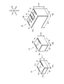
- FIG. 2 is a perspective view of the first packing box, the second packing box, and the third packing box in the article storage device of FIG. 1 as viewed obliquely from above;
- FIG. 2 is a perspective view of the base member, the first panel member, and the second panel member in the article storage device of FIG. 1 as seen obliquely from above;
- FIG. 2 is a perspective view showing the lower surface and the rear surface of a packing box in the article storage device of FIG. 1; 1. It is a figure which shows the engagement state of an engagement rail and a leg part in the article storage apparatus of FIG.
- FIG. 1 is a diagram (part 2) showing an example of loading a packing box on a base member in the article storage device of FIG. 1 ; 1.
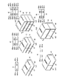
- FIG. 7 It is a figure which shows arrangement
- (a) is an AA cross-sectional schematic diagram of FIG. 7
- (b) is a BB cross-sectional schematic diagram of FIG. 7
- (c) is a CC cross-sectional schematic diagram of FIG.
- (d1) is a schematic cross-sectional view along D1-D1 in FIG. 8
- (d2) is a schematic cross-sectional view along D2-D2 in FIG.
- each of the front-rear, left-right, and up-down directions is defined with the vertical direction as the up-down direction, and for convenience, the front-rear direction is defined with the opening direction of each packing box as the front.
- the horizontal direction is defined according to the opening direction of each packing box, that is, the direction when the article storage device is viewed from the front.
- the front is indicated by Fr, the rear by Rr, the left by L, the right by R, the upper by U, and the lower by D.
- the left-right direction is also referred to as the width direction
- the front-rear direction is also referred to as the depth direction.
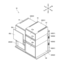
- an article storage device 10 of this embodiment includes a plurality of packing boxes 20 capable of accommodating articles, a base member 30 capable of loading the plurality of packing boxes 20, and a rear end portion of the base member 30. and a plurality of panel members 40 attached to and extending in the vertical direction and the horizontal direction.
- the article storage device 10 is mounted, for example, on a delivery vehicle, a trolley, or the like (not shown).
- each of the plurality of packing boxes 20 has a substantially rectangular parallelepiped shape.
- the multiple packing boxes 20 have a first packing box 21 , a second packing box 22 and a third packing box 23 .
- the first packing box 21 and the second packing box 22 have the same width dimension W1 and the same depth dimension D1.
- the first packing box 21 has a height dimension that is three times the unit height dimension H1, that is, 3 ⁇ H1.
- the second packing box 22 has a height dimension that is five times the unit height dimension H1, that is, 5 ⁇ H1.
- the third packing box 23 has a width dimension W2 that is approximately twice the width dimension W1, a depth dimension D1 that is the same as the first packing box 21 and the second packing box 22, and eight times the unit height dimension H1, i.e. It has a height dimension of 8 ⁇ H1.
- the first packing box 21, the second packing box 22, and the third packing box 23 are provided with door members 21a, 22a, and 23a capable of opening and closing openings that open forward.
- the door members 21a, 22a, and 23a may be electrically openable and closable, or may be manually openable and closable.
- first packing box 21, the second packing box 22, and the third packing box 23 are each provided with an electronic lock (not shown). With this electronic lock, the door members 21a, 22a, 23a are locked and unlocked with respect to the first packing box 21, the second packing box 22, and the third packing box 23, respectively.
- the electronic lock switches the door members 21a, 22a, 23a to the locked state and the unlocked state with respect to the first packing box 21, the second packing box 22, and the third packing box 23, respectively, by electric power.
- the base member 30 extends in the front-rear direction and the left-right direction and has a substantially rectangular flat plate shape when viewed from above.
- the base member 30 has a width dimension W3 that is approximately twice the width dimension W1 and substantially the same as the width dimension W2.
- the base member 30 has a depth dimension D2 that is greater than the depth dimension D1 of the first packing box 21, the second packing box 22 and the third packing box 23. As shown in FIG. Therefore, all of the first packing box 21, the second packing box 22, and the third packing box 23 can be loaded on the upper surface 30a of the base member 30 without protruding from the base member 30 when viewed from above.
- An engaging rail 51 is provided on the upper surface 30 a of the base member 30 .
- the engaging rails 51 provided on the upper surface 30a of the base member 30 are a pair of left and right rails extending in the front-rear direction with a predetermined distance L0 in the left-right direction.
- the pair of left and right engagement rails 51 are arranged side by side in the left-right direction, one set each on the left side region and the right side region of the base member 30 .
- the engaging rail 51 has a substantially L-shaped cross-section when viewed in the front-rear direction, and has projecting portions 51a projecting toward the engaging rails 51 forming a pair on the left and right at upper ends thereof.
- engaging rails 51 are provided on the upper surfaces 21b and 22b of the first packing box 21 and the second packing box 22.
- the engaging rails 51 have the same shape as the engaging rails 51 provided on the upper surface 30a of the base member 30, and are a pair of left and right rails extending in the front-rear direction separated by a predetermined distance L0 in the left-right direction. is.
- An engagement rail 51 is provided on the upper surface 23b of the third packing box 23.
- the engagement rails 51 provided on the upper surface 23b of the third packing box 23 have the same shape as the engagement rails 51 provided on the upper surfaces 21b and 22b of the first packing box 21 and the second packing box 22, and extend horizontally.
- a pair of left and right rails extending in the front-rear direction separated by a predetermined distance L0.
- a pair of left and right engagement rails 51 are provided in each of the left and right regions of the top surface 23b of the third packing box 23, and one pair in the central region of the top surface 23b of the third packing box 23.
- a set, a total of three sets, are arranged side by side in the left-right direction.
- the pair of left and right engaging rails 51 provided in the central region of the upper surface 23b of the third packing box 23 are arranged such that the left engaging rail 51 is provided in the left region of the upper surface 23b of the third packing box 23.
- the right engagement rail 51 is arranged on the left side of the right engagement rail 51 of the engagement rails 51, and the right engagement rail 51 is a pair of left and right engagements provided in the right region of the upper surface 23b of the third packing box 23. It is arranged on the right side of the left engaging rail 51 of the rails 51 .
- the lower surfaces 21c, 22c, and 23c of the first packing box 21, the second packing box 22, and the third packing box 23 are provided with legs that can be detachably engaged with the pair of left and right engagement rails 51.
- a portion 52 is provided.
- a plurality of legs 52 are arranged in the front-rear direction at the left and right ends of the lower surfaces 21c, 22c, and 23c of the first packing box 21, the second packing box 22, and the third packing box 23 (in this embodiment, 4) are provided.
- the leg portion 52 has a cylindrical shape projecting downward from the lower surfaces 21c, 22c, and 23c of the first packing box 21, the second packing box 22, and the third packing box 23, and has a flange portion 52a formed at the lower end.
- leg portions 52 provided at the left end portions of the lower surfaces 21c, 22c, and 23c of the first packing box 21, the second packing box 22, and the third packing box 23 and the leg portions 52 provided at the right end portions extend in the left-right direction. , they are provided at positions offset by the same distance in the left and right directions from the centers of the first packing box 21, the second packing box 22 and the third packing box 23 in the left-right direction.
- the flange portion 52a of the leg portion 52 provided at the left end portion of the first packing box 21 is placed on the base member 30.
- the flange portion 52a of the leg portion 52 provided at the right end engages with the projecting portion 51a of the left engaging rail 51 of the pair of left and right engaging rails 51 provided on the upper surface 30a of the base member 30.
- the right side of the pair of left and right engagement rails 51 provided on the upper surface 30a of the housing is engaged with the projecting portion 51a of the right side engagement rail 51, and is slid from the front to the rear.
- the first packing box 21 is engaged with the upper surface 30 a of the base member 30 and loaded on the upper surface 30 a of the base member 30 .
- the first packing box 21 When loading the first packing box 21 on the upper surface 21b of the first packing box 21, the upper surface 22b of the second packing box 22, or the upper surface 23b of the third packing box 23, the first packing box 21 is placed at the left end.
- the flange portions 52a of the provided leg portions 52 are engaged with a pair of left and right provided on the upper surface 21b of the first packing box 21, the upper surface 22b of the second packing box 22, or the upper surface 23b of the third packing box 23.
- the flange portion 52a of the leg portion 52 provided at the right end engages with the projecting portion 51a of the left engaging rail 51 of the rails 51.
- the first packing box 21 is engaged with the upper surface 21b of the different first packing box 21, the upper surface 22b of the second packing box 22, or the upper surface 23b of the third packing box 23, thereby , the upper surface 22b of the second packing box 22, or the upper surface 23b of the third packing box 23.
- the flange portion 52a of the leg portion 52 provided at the left end portion of the second packing box 22 is provided on the upper surface 30a of the base member 30.
- the flange portion 52a of the leg portion 52 provided at the right end portion is provided on the upper surface 30a of the base member 30 so as to engage with the projecting portion 51a of the left engagement rail 51 of the pair of left and right engagement rails 51. It is slid from the front to the rear while being engaged with the projecting portion 51a of the right engagement rail 51 of the pair of left and right engagement rails 51 . Thereby, the second packing box 22 is engaged with the upper surface 30 a of the base member 30 and loaded on the upper surface 30 a of the base member 30 .
- the second packing box 22 When loading the second packing box 22 on the upper surface 21b of the first packing box 21, the upper surface 22b of a different second packing box 22, or the upper surface 23b of the third packing box 23, the second packing box 22 is placed on the left end.
- the flanges 52a of the legs 52 provided on the upper surface 21b of the first packing box 21, the upper surface 22b of the different second packing box 22, or the upper surface 23b of the third packing box 23 are engaged with a pair of left and right sides.
- the flange portion 52a of the leg portion 52 provided at the right end engages with the projecting portion 51a of the left engaging rail 51 of the rails 51, and the flange portion 52a of the leg portion 52 is located on the upper surface 21b of the first packing box 21 and the second packing box 22, which is different.
- the second packing box 22 engages the top surface 21b of the first packing box 21, the top surface 22b of a different second packing box 22, or the top surface 23b of the third packing box 23, thereby It is loaded on the top surface 21b, the top surface 22b of a different second packing box 22, or the top surface 23b of the third packing box 23.
- the flange portion 52 a of the leg portion 52 provided at the left end portion of the third packing box 23 is placed on the upper surface 30 a of the base member 30 .
- the pair of left and right engagement rails 51 are engaged with the projecting portion 51a of the left engagement rail 51, and the right end portion
- the flange portions 52a of the leg portions 52 provided on the upper surface 30a of the base member 30 are provided on the right side region of the upper surface 30a of the base member 30 of the pair of left and right engaging rails 51 provided on the upper surface 30a of the base member 30.
- the pair of engagement rails 51 are slid from the front to the rear while being engaged with the projecting portion 51a of the right engagement rail 51 . Thereby, the third packing box 23 is engaged with the upper surface 30 a of the base member 30 and loaded on the upper surface 30 a of the base member 30 .
- each packing box 20 can be loaded on the base member 30 by engaging the legs 52 with the engaging rails 51 of the base member 30 or different packing boxes 20 .
- first packing box 21 and the second packing box 22 can be engaged with the base member 30 and loaded on the base member 30, and the first packing box 21 and the second packing box 22 can be moved to the lower first packing box. 21 and the second packing box 22, and can be loaded on the upper surface 21b, 22b of either the first packing box 21 or the second packing box 22.
- packing boxes 20 having different height dimensions can be stacked vertically by engaging with the base member 30 and the packing boxes 20 below, so that they do not move relative to the base member 30 and the packing boxes 20 below. Therefore, packing boxes 20 having different height dimensions can be combined vertically and loaded on the base member 30 with a high degree of freedom.
- the plurality of panel members 40 are vertically connected to the rear end portion of the base member 30 .
- the multiple panel members 40 have a first panel member 41 and a second panel member 42 .
- the first panel member 41 and the second panel member 42 are substantially rectangular parallelepipeds having a predetermined thickness in the front-rear direction and extending in the vertical and horizontal directions.
- the first panel member 41 and the second panel member 42 have the same dimensions.
- the height dimension of the first panel member 41 and the second panel member 42 is three times the unit height dimension H1, that is, has a height dimension of 3 ⁇ H1. Therefore, the height dimension of the first panel member 41 and the second panel member 42 is the same as the height dimension of the first packing box 21 .
- the width dimension of the first panel member 41 and the second panel member 42 is about twice the width dimension W1 and has a width dimension W4 that is substantially the same as the width dimension W3.
- the first panel member 41 is connected to the base member 30 while being placed on the rear end portion of the upper surface 30 a of the base member 30 .
- the second panel member 42 can be detachably connected to the first panel member 41 or a different second panel member 42 in the vertical direction.
- Claw portions 40 a are provided at the upper end portions of the left and right side surfaces of the first panel member 41 and the second panel member 42 .
- tightening levers 40b that can be engaged with the claw portions 40a are provided. Then, the tightening lever 40b of the second panel member 42 is engaged with the claw portion 40a of the first panel member 41 or the second panel member 42 arranged below the second panel member 42 . Thereby, the second panel member 42 is vertically connected to the first panel member 41 or the second panel member 42 arranged below the second panel member 42 .
- FIG. 3 shows an example in which a second panel member 42 is connected to the upper surface of the first panel member 41 and a different second panel member 42 is connected to the upper surface of the second panel member 42 .
- three panel members 40 specifically one first panel member 41 and two second panel members 42, are vertically connected.
- An upper surface connector 40c is provided on the upper surfaces of the first panel member 41 and the second panel member 42, and a lower surface connector 40d that can be electrically connected to the upper surface connector 40c is provided on the lower surface of the second panel member 42.
- the lower surface connector 40d is connected to the first panel member 41 arranged below the second panel member 42.
- it is electrically connected to the upper surface connector 40c of the second panel member 42 .
- a cap CP is fitted to the upper connector 40c of the panel member 40 arranged on the uppermost stage.
- the cap CP prevents foreign matter such as water and dust from entering the upper connector 40c of the panel member 40 arranged on the uppermost stage, and prevents the upper connector 40c of the panel member 40 arranged on the uppermost stage from being electrically connected to an unintended member. can be prevented.
- the panel member 40 is provided with a panel-side connector 400.
- the panel-side connector 400 includes a pedestal portion 400a, connector terminals 400b fixed to the pedestal portion 400a so as to face forward, and left and right terminals 400b fixed to the pedestal portion 400a to face forward while sandwiching the connector terminals 400b in the left-right direction. and a pair of positioning pins 400c.
- the base portion 400a is supported by the panel member 40 by a pair of left and right coil springs 400d.
- the front surface of the panel member 40 has openings in areas overlapping the connector terminals 400b and the positioning pins 400c when viewed from the front-rear direction. Therefore, the panel-side connector 400 is provided on the panel member 40 so that the connector terminals 400b and the positioning pins 400c can be accessed from the front of the panel member 40.
- each packing box 20 is provided with a packing box side connector 200 that can be electrically connected to the panel side connector 400 of the panel member 40 .
- the packing-box-side connector 200 includes connector terminals 200a fixed to the rear surface of the packing box 20 so as to face rearward, and left and right terminals fixed to the rear surface of the packing box 20 so as to face rearward with the connector terminals 200a interposed in the left-right direction. and a pair of bushings 200b.
- the bushing 200b has a shape that can be fitted with the positioning pin 400c of the panel-side connector 400. As shown in FIG.
- the packing-box-side connector 200 of each packing box 20 is connected to the panel-side connector 400 by fitting the positioning pin 400c of the panel-side connector 400 into the bushing 200b.
- the connector terminal 200a of the packing-box-side connector 200 and the connector terminal 400b of the panel-side connector 400 are connected to be electrically connected to the panel-side connector 400.
- the pair of left and right coil springs 400d provided on the panel member 40 can be used to correct dimensional errors of each packing box 20 and each panel member 40, assembly errors of the plurality of panel members 40, and contact between the engaging rails 51 and the legs 52. Looseness or the like is absorbed, and the packing-box-side connector 200 of each packing box 20 can be connected to the panel-side connector 400 in a reliably conducting state.
- the cargo box side connector 200 engages the legs 52 of the cargo box 20 with the engagement rails 51 provided on the upper surface 30a of the base member 30 so that the cargo box 20 is connected to the base.
- the packing box side connector 200 is provided at a first distance L1 above the lower end of the packing box 20, ie, the lower end of the leg 52 in the vertical direction.
- the packing box side connector 200 is provided at a position a second distance L2 from the left surface of the packing box 20 in the left-right direction.
- the second panel member 42 is provided with four panel-side connectors 400 like the first panel member 41 .
- the panel-side connector 400 provided on the first panel member 41 includes a panel-side upper left connector 401 a provided on the upper left region of the front surface of the first panel member 41 and a panel side connector 401 a provided on the lower left region of the front surface of the first panel member 41 .
- a panel-side lower left connector 401b provided on the front surface of the first panel member 41;
- a panel-side upper right connector 401c provided on the front upper right region of the first panel member 41; and a lower connector 401d.
- the panel-side lower left connector 401b and the panel-side lower right connector 401d are located at a first distance L1 upward from the upper surface 30a of the base member 30 in the vertical direction. placed in position. Therefore, in the present embodiment, the panel-side lower left connector 401b and the panel-side lower right connector 401d are provided at positions that are the first distance L1 above the lower surface of the first panel member 41 in the vertical direction.
- the panel-side lower left connector 401b is connected to the left side of the pair of left and right engagement rails 51 provided in the left region of the upper surface 30a of the base member 30 in the left-right direction.
- the panel-side lower right connector 401d is connected to the left side of a pair of left and right engagement rails 51 provided in the right region of the upper surface 30a of the base member 30 in the left-right direction. and the right engaging rail 51 to the left by a third distance L3.
- the third distance L3 is the left and right distance between the first packing box 21 and the second packing box 22 provided in the left region of the upper surface 30a of the base member 30 when the first panel member 41 is connected to the base member 30.
- the panel-side lower left connector 401b connects the first and second packing boxes 21 and 22 to each other.
- the distance is such that it is connected to the box-side connector 200 .
- the third distance L3 is such that the first packing box 21 and the second packing box 22 are provided in the right region of the upper surface 30a of the base member 30 while the first panel member 41 is connected to the base member 30.
- the panel-side lower right connector 401d is connected to the first packing box 21 and the second packing box 22. It is the distance which becomes the position connected with the packing box side connector 200 of . Therefore, in a state where the first panel member 41 is connected to the base member 30, the first packing box 21 or the second packing box 22 is connected to the pair of left and right engagement rails 51 provided on the left side region of the upper surface 30a of the base member 30.
- the packing box side connector 200 of the first packing box 21 or the second packing box 22 is connected to the panel side lower left connector 401b. Connect and conduct.
- the first packing box 21 or the second packing box 22 is attached to a pair of left and right engaging rails provided on the right side region of the upper surface 30a of the base member 30.
- the packing box side connector 200 of the first packing box 21 or the second packing box 22 is connected to the panel side lower right connector. 401d to conduct.
- the flange portion 52a of the leg portion 52 provided at the left end of the third packing box 23 is provided on the upper surface 30a of the base member 30.
- the pair of left and right engagement rails 51 are engaged with the projecting portion 51a of the left engagement rail 51, and the right end portion
- the flange portions 52a of the leg portions 52 provided on the upper surface 30a of the base member 30 are provided on the right side region of the upper surface 30a of the base member 30 of the pair of left and right engaging rails 51 provided on the upper surface 30a of the base member 30.
- the panel side When loaded on the upper surface 30a of the base member 30 by engaging with the projecting portion 51a of the right engaging rail 51 of the pair of engaging rails 51 and engaging with the upper surface 30a of the base member 30, the panel side
- the lower left connector 401 b connects with the packing box side connector 200 of the third packing box 23 . Therefore, with the first panel member 41 connected to the base member 30 , the third packing box 23 is attached to the left side of the pair of left and right engagement rails 51 provided on the left side of the upper surface 30 a of the base member 30 .
- the left and right leg portions 52 are engaged with the matching rail 51 and the right engagement rail 51 of the pair of left and right engagement rails 51 provided in the right region of the upper surface 30a of the base member 30, thereby 30, the packing box side connector 200 of the third packing box 23 is connected to the panel side lower left connector 401b to conduct.
- the panel-side upper left connector 401a and the panel-side upper right connector 401c are provided at positions above the lower surface of the first panel member 41 (twice the unit height dimension H1) + (first distance L1) in the vertical direction. It is The panel-side upper left connector 401a is provided at the same position as the panel-side lower left connector 401b in the horizontal direction. The panel-side upper right connector 401c is provided at the same position as the panel-side lower right connector 401d in the horizontal direction.
- the panel-side connectors 400 provided on the second panel member 42 are the panel-side upper left connector 402a provided on the upper left region of the front surface of the second panel member 42 and the panel side connector 402a provided on the lower left region of the front surface of the second panel member 42. a panel-side lower left connector 402b provided on the front surface of the second panel member 42; and a lower connector 402d.
- the panel-side lower left connector 402b and the panel-side lower right connector 402d are provided below the panel-side upper left connector 402a and the panel-side upper right connector 402c on the front surface of the second panel member 42, and the second panel member 42 is connected to the first panel. It is connected to the first panel member 41 adjacent to the upper part of the member 41, and the legs 52 of the first packing box 21 are engaged with the engagement rails 51 provided on the upper surface 30a of the base member 30 to engage the first packing box.
- one packing box 21 is loaded on the upper surface 30a of the base member 30, it is provided at a position that is a first distance L1 above the upper surface of the first packing box 21 in the vertical direction.
- the height dimension of the first packing box 21 and the height dimension of the first panel member 41 and the height dimension of the second panel member 42 are all three times the unit height dimension H1, that is, 3 ⁇ H1. Since they have the same dimensions, the panel-side lower left connector 402b and the panel-side lower right connector 402d are provided at positions that are the first distance L1 above the lower surface of the second panel member 42 in the vertical direction.
- the panel-side lower left connector 402b is positioned at the same position as the panel-side upper left connector 401a and the panel-side lower left connector 401b of the first panel member 41 in the horizontal direction. is provided.
- the panel-side lower right connector 402d is the same as the panel-side upper right connector 401c and the panel-side lower right connector 401d of the first panel member 41 in the horizontal direction. placed in position.
- the second panel member 42 is connected to the first panel member 41 above and adjacent to it, and the leg portion 52 of the first packing box 21 is provided in the left region of the upper surface 30a of the base member 30.
- a different first packing box 21 or second packing box 22 is attached to the first packing box 21.
- the panel side lower left connector 402b It connects with the packing box side connector 200 of the first packing box 21 or the second packing box 22 loaded on the upper surface 21 b of the first packing box 21 .
- the second panel member 42 is connected to the first panel member 41 above and adjacent to it, and the legs 52 of the first packing box 21 are located on the right side of the upper surface 30 a of the base member 30 .
- the different first packing box 21 or the second packing box 22 is connected to the first When loaded on the upper surface 21b of the first packing box 21 so that the left and right legs 52 are engaged with the pair of left and right engaging rails 51 provided on the upper surface 21b of the packing box 21, the lower right of the panel side
- the connector 402 d is connected to the packing box side connector 200 of the first packing box 21 or the second packing box 22 loaded on the upper surface 21 b of the first packing box 21 .
- the second panel member 42 is connected to the first panel member 41 above and adjacent to it, and the leg portion 52 of the first packing box 21 is located in the left region of the upper surface 30a of the base member 30.
- the first packing box 21 is loaded on the upper surface 30a of the base member 30 by engaging with the provided engagement rails 51, the different first packing box 21 or the second packing box 22 is attached to the first packing box.
- the first packing box side connector 200 of the first packing box 21 or the second packing box 22 loaded on the upper surface 21b of the container 21 is connected to the first panel member 41 adjacent to the upper side of the first panel member 41 and connected to the second panel member 41.
- 42 is connected to the lower left connector 402b on the panel side of 42 to conduct.
- the second panel member 42 is connected to the first panel member 41 above and adjacent to it, and the legs 52 of the first packing box 21 are located on the right side of the upper surface 30 a of the base member 30 .
- the different first packing box 21 or the second packing box 22 is connected to the first
- the left and right legs 52 are engaged with the pair of left and right engagement rails 51 provided on the top surface 21b of the first cargo box 21
- the first cargo is loaded on the top surface 21b of the first cargo box 21.
- the packing box side connector 200 of the first packing box 21 or the second packing box 22 loaded on the upper surface 21b of the box 21 is a second panel connected to the first panel member 41 adjacent to the upper side of the first panel member 41. It is connected to the lower right connector 402d on the panel side of the member 42 and conducts.
- the panel-side upper left connector 402a and the panel-side upper right connector 402c are provided above the panel-side lower left connector 402b and the panel-side lower right connector 402d in the second panel member 42, and the second panel member 42 is connected to the first panel member 41. and connected to the first panel member 41 above and adjacent to the second cargo box 22, and the leg portions 52 of the second cargo box 22 are engaged with the engagement rails 51 provided on the upper surface 30a of the base member 30 to engage the second cargo box.
- the box 22 When the box 22 is loaded on the upper surface 30a of the base member 30, it is provided at a position that is a first distance L1 above the upper surface of the second packing box 22 in the vertical direction.
- the height dimension of the second packing box 22 is five times the unit height dimension H1, that is, 5 ⁇ H1 and the height dimension of the first panel member 41 and the second panel member 42 is the unit Since the height dimension H1 is three times, that is, 3 ⁇ H1, the panel-side upper left connector 402a and the panel-side upper right connector 402c extend upward from the lower surface of the second panel member 42 (the unit height dimension H1 )+(first distance L1).
- the panel-side upper left connector 402a is provided at the same position as the panel-side lower left connector 402b in the horizontal direction.
- the panel-side upper right connector 402c is provided at the same position as the panel-side lower right connector 402d in the horizontal direction.
- the second panel member 42 is connected to the first panel member 41 above and adjacent to it, and the leg portion 52 of the second packing box 22 is provided in the left region of the upper surface 30a of the base member 30.
- the first packing box 21 or a different second packing box 22 is attached to the second packing box 22.
- the upper left connector 402a on the panel side It connects with the packing box side connector 200 of the first packing box 21 or the second packing box 22 loaded on the upper surface 22 b of the second packing box 22 .
- the second panel member 42 is above and adjacent to the first panel member 41 and connected to the first panel member 41 , and the legs 52 of the second packing box 22 are located on the right side of the upper surface 30 a of the base member 30 .
- the second packing box 22 is loaded on the upper surface 30a of the base member 30 by engaging with the engaging rails 51 provided in the first packing box 21 or a different second packing box 22, the second packing box 22 is attached to the second packing box 22
- the panel side upper right connector 402c is connected to the packing box side connector 200 of the first packing box 21 or the second packing box 22 loaded on the upper surface 22b of the second packing box 22;
- the second panel member 42 is connected to the first panel member 41 above and adjacent to it, and the legs 52 of the second packing box 22 are located in the left region of the upper surface 30a of the base member 30.
- the first packing box 21 or a different second packing box 22 is attached to the second packing box.
- the packing box side connector 200 of the first packing box 21 or the second packing box 22 loaded on the upper surface 22b of the 22 is a second panel member connected to the first panel member 41 adjacent to the upper side of the first panel member 41. 42 and the upper left connector 402a on the panel side to conduct.
- the second panel member 42 is above and adjacent to the first panel member 41 and connected to the first panel member 41
- the legs 52 of the second packing box 22 are located on the right side of the upper surface 30 a of the base member 30 .
- the second packing box 22 is attached to the second packing box 22
- the left and right legs 52 are engaged with the pair of left and right engagement rails 51 provided on the top surface 22b of the second cargo box 22
- the second cargo is loaded on the top surface 22b of the second cargo box 22.
- the packing box side connector 200 of the first packing box 21 or the second packing box 22 loaded on the upper surface 22b of the box 22 is a second panel connected to the first panel member 41 adjacent to the upper side of the first panel member 41. It is connected to the upper right connector 402c on the panel side of the member 42 and conducts.
- the packing box side connector 200 of each packing box 20 is connected to the first panel member. 41 or the panel-side connector 400 of the second panel member 42 , and each packing box 20 can be supplied with electric power via the first panel member 41 or the second panel member 42 .
- the article storage device 10 includes a plurality of panel members 40 provided with panel-side connectors 400, and each packing box 20 is provided with a packing box-side connector 200 that can be electrically connected to the panel-side connector 400. Since the second panel member 42 can be vertically connected above the first panel member 41 connected to the base member 30, a plurality of packing boxes 20 can be stacked vertically and loaded on the base member 30. Even in this case, the packing box-side connector 200 of each packing box 20 can be electrically connected to the panel-side connector 400 of the first panel member 41 or the second panel member 42, and each packing box 20 can connect to the first panel member 41 or Power can be supplied through the second panel member 42 .
- each packing box 20 does not need to be provided with a configuration for mutual conduction between the packing boxes 20, and the packing boxes 20 can be configured simply. be able to.
- each packing box 20 operates, for example, the electronic lock described above with electric power supplied via the first panel member 41 or the second panel member 42 . Further, each packing box 20 may open and close the door members 21a, 22a, and 23a by electric power supplied through the first panel member 41 or the second panel member 42. As shown in FIG.
- FIG. 7 ⁇ Example of loading on the base member of the packing box>
- FIG. 8 Each packing box 20 is loaded by being engaged with an engaging rail 51 provided on the base member 30 or the packing box 20 adjacent below.
- the panel-side connector 400 that conducts with the packing box-side connector 200 of the packing box 20 is hatched.
- one first packing box 21 is loaded on each of the left side area and the right side area of the upper surface 30a of the base member 30 . Only the first panel member 41 connected to the base member 30 is attached to the panel member 40 . At this time, the packing box side connector 200 of the first packing box 21 loaded on the left side area of the upper surface 30a of the base member 30 is electrically connected to the panel side lower left connector 401b of the first panel member 41, and the upper surface 30a of the base member 30 is connected. The packing-box-side connector 200 of the first packing box 21 loaded in the right-hand area of is electrically connected to the panel-side lower-right connector 401 d of the first panel member 41 .
- the panel member 40 has a first panel member 41 connected to the base member 30 and a second panel member 42 adjacent to the upper side of the first panel member 41 and connected to the first panel member 41 .
- the packing box side connector 200 of the first packing box 21 stacked on the left side area of the upper surface 30a of the base member 30 is electrically connected to the panel side lower left connector 401b of the first panel member 41
- the packing box side connector 200 of the second packing box 21 stacked on the left side area of the upper surface 30 a of the base member 30 is electrically connected to the panel side lower left connector 402 b of the second panel member 42 .
- the packing box side connector 200 of the first packing box 21 stacked on the right side area of the upper surface 30a of the base member 30 is electrically connected to the panel side lower right connector 401d of the first panel member 41
- the packing box side connector 200 of the first packing box 21 in the second stage from the bottom stacked on the right side area of the upper surface 30 a of the base member 30 is electrically connected to the panel side right lower connector 402 d of the second panel member 42 .
- the panel member 40 includes a first panel member 41 connected to the base member 30, a second panel member 42 adjacent to the upper side of the first panel member 41 and connected to the first panel member 41, and a second panel member 42 that is connected to the first second panel member 42 adjacent to and above the first second panel member 42 .
- the packing box side connector 200 of the first packing box 21 stacked on the left side area of the upper surface 30a of the base member 30 is electrically connected to the panel side lower left connector 401b of the first panel member 41
- the packing box side connector 200 of the first packing box 21 in the second stage from the bottom stacked on the left side area of the upper surface 30 a of the base member 30 is electrically connected to the panel side lower left connector 402 b of the first second panel member 42 .
- the packing box side connector 200 of the first packing box 21 on the third stage from the bottom stacked on the left side area of the upper surface 30a of the base member 30 is electrically connected to the panel side lower left connector 402b of the second panel member 42. do.
- the packing box side connector 200 of the first packing box 21 stacked on the right side area of the upper surface 30a of the base member 30 is electrically connected to the panel side lower right connector 401d of the first panel member 41
- the packing box side connector 200 of the first packing box 21 in the second stage from the bottom stacked on the right side area of the upper surface 30a of the base member 30 is electrically connected to the panel side lower right connector 402d of the first second panel member 42.
- the packing box side connector 200 of the third packing box 21 stacked on the right side area of the upper surface 30a of the base member 30 is connected to the panel side lower right connector 402d of the second second panel member 42. and conduct.
- the second packing boxes 22 are loaded one each on the left side area and the right side area of the upper surface 30a of the base member 30 . Only the first panel member 41 connected to the base member 30 is attached to the panel member 40 . At this time, the packing box side connector 200 of the second packing box 22 loaded on the left side area of the upper surface 30a of the base member 30 is electrically connected to the panel side lower left connector 401b of the first panel member 41, and the upper surface 30a of the base member 30 is connected. The packing-box-side connector 200 of the second packing box 22 loaded in the right-hand area of is electrically connected to the panel-side lower-right connector 401 d of the first panel member 41 .
- the panel member 40 has a first panel member 41 connected to the base member 30 and a second panel member 42 adjacent to the upper side of the first panel member 41 and connected to the first panel member 41 .
- the packing box side connector 200 of the second packing box 22 in the first stage from the bottom stacked on the left side area of the upper surface 30a of the base member 30 is electrically connected to the panel side lower left connector 401b of the first panel member 41
- the packing box side connector 200 of the second packing box 22 stacked on the left side area of the upper surface 30 a of the base member 30 is electrically connected to the panel side upper left connector 402 a of the second panel member 42 .
- the packing box side connector 200 of the first packing box 22 stacked on the right side area of the upper surface 30a of the base member 30 is electrically connected to the panel side lower right connector 401d of the first panel member 41
- the packing box side connector 200 of the second packing box 22 stacked on the right side area of the upper surface 30 a of the base member 30 is electrically connected to the panel side upper right connector 402 c of the second panel member 42 .
- the panel member 40 includes a first panel member 41 connected to the base member 30, a second panel member 42 adjacent to the upper side of the first panel member 41 and connected to the first panel member 41, and a second panel member 42 that is connected to the first second panel member 42 adjacent to and above the first second panel member 42 .
- the packing box side connector 200 of the second packing box 22 in the first stage from the bottom stacked on the left side area of the upper surface 30a of the base member 30 is electrically connected to the panel side lower left connector 401b of the first panel member 41
- the packing box side connector 200 of the second packing box 22 stacked on the left side area of the upper surface 30 a of the base member 30 is electrically connected to the panel side upper left connector 402 a of the first second panel member 42 .
- the packing box side connector 200 of the first packing box 21 stacked on the right side area of the upper surface 30a of the base member 30 is electrically connected to the panel side lower right connector 401d of the first panel member 41
- the packing box side connector 200 of the first packing box 21 in the second stage from the bottom stacked on the right side area of the upper surface 30a of the base member 30 is electrically connected to the panel side lower right connector 402d of the first second panel member 42.
- the packing box side connector 200 of the third packing box 21 stacked on the right side area of the upper surface 30a of the base member 30 is connected to the panel side lower right connector 402d of the second second panel member 42. and conduct.
- the panel member 40 includes a first panel member 41 connected to the base member 30, a second panel member 42 adjacent to the upper side of the first panel member 41 and connected to the first panel member 41, and a second panel member 42 that is connected to the first second panel member 42 adjacent to and above the first second panel member 42 .
- the packing box side connector 200 of the second packing box 22 in the first stage from the bottom stacked on the left side area of the upper surface 30a of the base member 30 is electrically connected to the panel side lower left connector 401b of the first panel member 41
- the packing box side connector 200 of the second packing box 22 stacked on the left side area of the upper surface 30 a of the base member 30 is electrically connected to the panel side upper left connector 402 a of the first second panel member 42 .
- the packing box side connector 200 of the first packing box 22 stacked on the right side area of the upper surface 30a of the base member 30 is electrically connected to the panel side lower right connector 401d of the first panel member 41
- the packing box side connector 200 of the first packing box 21 in the second stage from the bottom stacked on the right side area of the upper surface 30 a of the base member 30 is electrically connected to the panel side upper right connector 402 c of the first second panel member 42
- the packing box side connector 200 of the first packing box 21 in the third stage from the bottom stacked on the right side area of the upper surface 30a of the base member 30 is electrically connected to the panel side upper right connector 402c of the second panel member 42. do.
- the third packing box 23 is loaded on the upper surface 30a of the base member 30, and one each of the left side area and the right side area of the upper surface 23b of the third packing box 23 is provided.
- One packing box 21 is loaded.
- the panel member 40 includes a first panel member 41 connected to the base member 30, a second panel member 42 adjacent to the upper side of the first panel member 41 and connected to the first panel member 41, and a second panel member 42 that is connected to the first second panel member 42 adjacent to and above the first second panel member 42 .
- the packing box side connector 200 of the third packing box 23 loaded on the upper surface 30 a of the base member 30 is electrically connected to the panel side lower left connector 401 b of the first panel member 41 .
- the packing box side connector 200 of the first packing box 21 loaded on the left side area of the upper surface 23b of the third packing box 23 is electrically connected to the panel side upper left connector 402a of the second panel member 42
- the packing box side connector 200 of the first packing box 21 loaded on the right side area of the upper surface 23 b of the third packing box 23 is electrically connected to the panel side upper right connector 402 c of the second second panel member 42 .
- packing boxes 20 of different sizes can be arranged in various ways. Electric power can be supplied to each packing box 20 even when it is loaded. Also, by minimizing the number of second panel members 42 to be mounted, the number of panel-side connectors 400 that are not electrically connected to the packing box-side connector 200 can be reduced.
- a dummy connector 201 is provided on the rear surface of each packing box 20 .
- the dummy connector 201 has, for example, a configuration in which the connector terminals 200a are omitted from the packing-box-side connector 200.
- the dummy connector 201 has a pair of left and right bushes that can be fitted with the positioning pins 400c of the panel-side connector 400.
- the dummy connector 201 functions as a connector protection member that covers and protects the panel side connector 400 that is not connected to the packing box side connector 200 when the packing box 20 is loaded on the base member 30 .
- the dummy connector 201 engages with the panel member 40 by fitting the positioning pins 400c of the panel-side connector 400 into the pair of left and right bushes when the packing box 20 is loaded on the base member 30. It also functions as an engaging member.
- Two dummy connectors 201 are provided on the rear surface of the first packing box 21 .
- the two dummy connectors 201 provided on the rear surface of the first packing box 21 are provided at the same positions as the packing box side connectors 200 in the left-right direction.
- the two dummy connectors 201 provided on the rear surface of the first packing box 21 are positioned at (unit height dimension H1) + (first distance L1) above the bottom surface of the first packing box 21 in the vertical direction.
- a first dummy connector 211a provided, and a second dummy connector 211b provided at a position of (twice the unit height dimension H1) + (first distance L1) upward from the lower surface of the first packing box 21. has Therefore, the first dummy connector 211a and the second dummy connector 211b are vertically aligned together with the packing box side connector 200 above the packing box side connector 200 at a unit height dimension H1 interval.
- Two dummy connectors 201 are provided on the rear surface of the second packing box 22 .
- the two dummy connectors 201 provided on the rear surface of the second packing box 22 are provided at the same positions as the packing box side connectors 200 in the left-right direction.
- the two dummy connectors 201 provided on the rear surface of the second packing box 22 extend upward from the bottom surface of the second packing box 22 by (twice the unit height dimension H1) + (first distance L1).
- a first dummy connector 221a provided at a position where the first dummy connector 221a and a second dummy connector 221a provided at a position upward from the lower surface of the second packing box 22 (three times the unit height dimension H1) + (first distance L1) and a connector 221b.
- Nine dummy connectors 201 are provided on the rear surface of the third packing box 23 .
- four dummy connectors 201 are provided at the same positions as the packing box side connectors 200 in the left-right direction.
- the four dummy connectors 201 provided at the same position as the packing box side connector 200 in the left-right direction are positioned at (twice the unit height dimension H1) + (first distance L1) upward from the bottom surface in the vertical direction. , and from the bottom upward (three times the unit height dimension H1) + (first distance L1), and from the bottom upward (five times the unit height dimension H1) + (first distance L1).
- the panel-side upper right connector 401c and the panel-side lower right connector 401d of the first panel member 41 and the panel-side upper right connector 402c and the panel-side lower right connector of the second panel member 42 It is provided at the same position as 402d.
- the remaining five dummy connectors 201 out of the nine dummy connectors 201 provided on the rear surface of the third packing box 23 are positioned at a first distance L1 upward from the bottom surface and upward from the bottom surface ( (2 times the unit height dimension H1) + (first distance L1), the position upward from the bottom surface (3 times the unit height dimension H1) + (first distance L1), and the position upward from the bottom surface To (five times the unit height dimension H1) + (first distance L1) and a position upward from the bottom surface (six times the unit height dimension H1) + (first distance L1) is provided.
- the packing box side of the first packing box 21 from the bottom is The connector 200 is connected to the panel side lower left connector 401b of the first panel member 41 to conduct.
- the second dummy connector 211 b provided on the first packing box 21 on the first stage from the bottom engages with the panel-side upper left connector 401 a of the first panel member 41 .
- the packing box side connector 200 of the first packing box 21 on the second stage from the bottom is connected to the panel side lower left connector 402b of the first second panel member 42 to conduct.
- the second dummy connector 211b provided on the first packing box 21 on the second stage from the bottom engages with the panel-side upper left connector 402a of the first second panel member 42 .
- the packing-box-side connector 200 of the first packing box 21 on the third stage from the bottom is connected to the panel-side lower-left connector 402b of the second panel member 42 on the second side to establish electrical continuity.
- the second dummy connector 211b provided on the first packing box 21 on the third stage from the bottom engages with the panel-side upper left connector 402a of the second panel member 42 on the second side.
- the packing box side connector 200 of the first packing box 21 from the bottom is connected. is connected to the panel-side lower right connector 401d of the first panel member 41 to conduct.
- the second dummy connector 211 b provided on the first packing box 21 on the first stage from the bottom engages with the panel-side upper right connector 401 c of the first panel member 41 .
- the packing box side connector 200 of the first packing box 21 in the second row from the bottom is connected to the panel side lower right connector 402d of the first second panel member 42 to conduct.
- the second dummy connector 211b provided on the first packing box 21 on the second stage from the bottom engages with the panel-side upper right connector 402c of the first second panel member 42 .
- the packing box side connector 200 of the first packing box 21 on the third stage from the bottom is connected to the panel side right lower connector 402d of the second panel member 42 to conduct.
- the second dummy connector 211b provided on the first packing box 21 on the third stage from the bottom engages with the panel-side upper right connector 402c of the second panel member 42, which is the second one.
- the second dummy connector 211b provided on each first packing box 21 is electrically connected to the packing box side connector 200 among the panel side connectors 400 provided on the first panel member 41 and the second panel member 42.
- the panel-side connector 400 is engaged with the panel-side connector 400 that is not connected, and the panel-side connector 400 that is not electrically connected to the packing box side connector 200 is covered and protected.
- the second dummy connector 211b of the first packing box 21 functions as a connector protection member that protects the panel side connector 400 that is not electrically connected to the packing box side connector 200, and is not connected to the packing box side connector 200.
- the second dummy connector 211b of the first packing box 21 functions as a panel engaging member that engages with the panel member 40, and can support the packing box 20 on the panel member 40, so that the packing box 20 can be attached to the panel. Positional deviation with respect to the member 40 can be suppressed, and electrical continuity between the packing-box-side connector 200 and the panel-side connector 400 can be ensured.
- the packing box side connector 200 of the second packing box 22 in the lower stage is the first. It connects with the panel side lower left connector 401b of the 1 panel member 41 and conducts.
- the first dummy connector 221a provided on the lower second packing box 22 is engaged with the panel-side upper left connector 401a of the first panel member 41, and the second dummy provided on the lower second packing box 22 is engaged.
- the connector 221b engages with the panel side lower left connector 402b of the second panel member 42 .
- the packing box side connector 200 of the second packing box 22 on the upper stage is connected to the panel side upper left connector 402a of the second panel member 42 to conduct.
- the packing box side connector 200 of the lower second packing box 22 is connected to the first panel member 41 . It is connected to the lower right connector 401d on the panel side and conducts.
- the first dummy connector 221a provided in the lower second packing box 22 is engaged with the panel-side upper right connector 401c of the first panel member 41, and the second dummy provided in the lower second packing box 22 is engaged.
- the connector 221b engages with the panel side lower right connector 402d of the second panel member 42 .
- the packing box side connector 200 of the second packing box 22 on the upper stage is connected to the panel side upper right connector 402c of the second panel member 42 to conduct.
- the two dummy connectors 201 provided on the lower second packing box 22 are the packing box side connectors 200 among the panel side connectors 400 provided on the first panel member 41 and the second panel member 42. It engages with the panel-side connector 400 that is not conducting, and covers and protects the panel-side connector 400 that is not conducting with the packing box side connector 200.
- the dummy connector 201 functions as a connector protection member that protects the panel-side connector 400 that is not electrically connected to the packing box-side connector 200, and protects the panel-side connector 400 that is not electrically connected to the packing box-side connector 200 from water and dust.
- the dummy connector 201 functions as a panel engaging member that engages with the panel member 40, and can support the packing box 20 on the panel member 40, so that the packing box 20 is displaced with respect to the panel member 40. can be suppressed, and electrical connection between the packing-box-side connector 200 and the panel-side connector 400 can be ensured.
- the second packing box 22 is located on the first level from the bottom, the first packing box 21 is located on the second level from the bottom, and the third level from the bottom is provided.
- the packing box side connector 200 of the second packing box 22 arranged in the first stage from the bottom is connected to the panel side lower right connector 401d of the first panel member 41. to conduct.
- the first dummy connector 221a provided on the second packing box 22 arranged on the first stage from the bottom engages with the panel-side upper right connector 401c of the first panel member 41, and is arranged on the first stage from the bottom.
- the second dummy connector 221b provided on the second packing box 22 is engaged with the panel side lower right connector 402d of the first second panel member 42 .
- the packing box side connector 200 of the first packing box 21 arranged in the second row from the bottom is connected to the panel side upper right connector 402c of the first second panel member 42 to conduct.
- the first dummy connector 211a provided on the first packing box 21 arranged on the second stage from the bottom engages with the panel-side lower right connector 402d of the second panel member 42 .
- the packing-box-side connector 200 of the first packing box 21 arranged in the third row from the bottom is connected to the panel-side upper-right connector 402c of the second panel member 42 to conduct.
- each dummy connector 201 provided on the first packing box 21 and the second packing box 22 is one of the panel side connectors 400 provided on the first panel member 41 and the second panel member 42. It engages with the panel side connector 400 that is not conducting with the connector 200, and covers and protects the panel side connector 400 that is not conducting with the packing box side connector 200.
- the dummy connector 201 functions as a connector protection member that protects the panel-side connector 400 that is not electrically connected to the packing box-side connector 200, and protects the panel-side connector 400 that is not electrically connected to the packing box-side connector 200 from water and dust.
- the dummy connector 201 functions as a panel engaging member that engages with the panel member 40, and can support the packing box 20 on the panel member 40, so that the packing box 20 is displaced with respect to the panel member 40. can be suppressed, and electrical connection between the packing-box-side connector 200 and the panel-side connector 400 can be ensured.
- the first packing box 21 is provided with the first dummy connector 211a and the second dummy connector 211b in this manner, the first packing box 21 can be connected to the base member 30, the first packing box 21, and the second packing box 21.
- the panel-side connectors 400 provided on the first panel member 41 and the second panel member 42, the panel that is not electrically connected to the packing-box-side connector 200 regardless of which upper surface of the packing box 22 is engaged and loaded.
- the first dummy connector 211a and the second dummy connector 211b are engaged with the side connector 400 to cover and protect the panel side connector 400 that is not electrically connected to the packing box side connector 200.
- the third packing box 23 is loaded on the upper surface 30a of the base member 30, and one each on the left side area and the right side area of the upper surface 23b of the third packing box 23.
- the packing box side connector 200 of the third packing box 23 is connected to the panel side lower left connector 401b of the first panel member 41 and conducts.
- the four dummy connectors 201 provided at the same position in the left-right direction as the packing box side connector 200 of the third packing box 23 are, in order from the bottom, the panel side upper left connector 401a of the first panel member 41, one It engages with the lower left panel connector 402b of the first second panel member 42, the upper left panel connector 402a of the first second panel member 42, and the lower left panel connector 402b of the second second panel member 42. .
- the remaining five dummy connectors 201 out of the nine dummy connectors 201 provided on the rear surface of the third packing box 23 are, in order from the bottom, the panel side lower right connector 401d of the first panel member 41, the third Panel-side upper right connector 401c of the first panel member 41, panel-side lower right connector 402d of the first second panel member 42, panel-side upper right connector 402c of the first second panel member 42, second second It engages with the panel side lower right connector 402 d of the panel member 42 .
- the packing box side connector 200 of the first packing box 21 loaded on the left side area of the upper surface 23b of the third packing box 23 is connected to the panel side upper left connector 402a of the second panel member 42 to conduct.
- the packing box side connector 200 of the first packing box 21 loaded on the right side area of the upper surface 23b of the third packing box 23 is connected to the panel side upper right connector 402c of the second second panel member 42 to conduct.
- the third packing box 23 is provided with the nine dummy connectors 201 in this way, even when the packing box 20 is loaded on the upper surface 23b of the third packing box 23, the first panel member 41 and the two Of the panel-side connectors 400 provided on the two-panel member 42, the dummy connector 201 is engaged with the panel-side connector 400 that is not conducting with the packing box side connector 200, and the panel that is not conducting with the packing box side connector 200 is engaged.
- the side connector 400 can be covered and protected.
- the dummy connector 201 functions as a connector protection member that covers and protects the panel side connector 400 that is not electrically connected to the packing box side connector 200, and also serves as a panel engagement member that engages with the panel member 40.
- the connector protection member and the panel engaging member are assumed to function as members, they may be separate members.
- a plurality of packing boxes capable of accommodating articles
- An article storage device comprising a base member (base member 30) capable of loading the plurality of packing boxes, Engagement portions (engagement rails 51) are provided on the upper surface of the base member (upper surface 30a) and the upper surface of the packing box (upper surfaces 21b, 22b), Engaged portions (leg portions 52) that can be detachably engaged with the engaging portions are provided on the lower surfaces (lower surfaces 21c, 22c) of the packing box,
- the plurality of packing boxes have a first packing box (first packing box 21) and a second packing box (second packing box 22) having the same width dimension and different height dimensions, Each of the packing boxes can be loaded on the base member by engaging the engaged portion with the engaging portion of the base member or a different packing box.
- the first packing box and the second packing box can be engaged with the base member and loaded on the base member, and the first packing box and the second packing box can be connected to the lower first packing box and the second packing box. It can be engaged with any of the second packing boxes and loaded on top of either the first packing box or the second packing box.
- packing boxes of different height dimensions can be engaged with the base member and the lower packing box and stacked vertically, so that the packing boxes of different heights can be loaded without moving with respect to the base member and the lower packing box. Packing boxes of different dimensions can be combined with a high degree of freedom in the vertical direction and loaded on the base member.
- a plurality of packing boxes capable of accommodating articles; a base member (base member 30) capable of loading the plurality of packing boxes; A panel member (panel member 40) provided with a panel-side connector (panel-side connector 400), and an article storage device (article storage device 10), An engaging portion (engaging rail 51) is provided on the upper surface (upper surface 30a) of the base member,
- the packing box is provided with a packing box side connector (packing box side connector 200) that can be electrically connected to the panel side connector, and the lower surface (lower surfaces 21c, 22c) of the packing box is detachable from the engaging portion.
- An engaged portion (leg portion 52) that can be engaged with is provided,
- the plurality of packing boxes have a first packing box (first packing box 21) and a second packing box (second packing box 22) having the same width dimension and different height dimensions, the panel member is connected to the base member;
- the article storage device wherein each of the packing boxes can be loaded on the base member with the engaged portion engaging with the engaging portion of the base member.
- the first packing box and the second packing box can be engaged with the base member to be loaded on the base member, and the first packing box and the second packing box are connected to the base member.
- the first packing box and the second packing box are connected to the base member.
- packing boxes with different height dimensions can be loaded by being connected to the base member and the panel member, so that packing boxes with different height dimensions can be combined with a high degree of freedom by connecting them to the base member and the panel member. It can be loaded on the base member.
- the article storage device further comprising a plurality of panel members (panel members 40) provided with panel-side connectors (panel-side connectors 400),
- the packing box is provided with a packing box side connector (packing box side connector 200) that can conduct with the panel side connector
- the plurality of panel members have a first panel member (first panel member 41) and a second panel member (second panel member 42), the first panel member is connected to the base member;
- the article storage device, wherein the second panel member can be detachably connected to the first panel member or a different second panel member in a vertical direction.
- each packing box is provided with a packing-box-side connector that can be electrically connected to the panel-side connector, and the second panel is connected to the base member. Since the second panel member can be vertically connected above the first panel member, even when a plurality of packing boxes are vertically stacked and loaded on the base member, the packing box side connector of each packing box is connected to the first panel member. It becomes possible to conduct with the panel-side connector of the first panel member or the second panel member, and each packing box can receive power supply via the first panel member or the second panel member.
- the article storage device is provided with a connector protection member (dummy connector 201) that protects the panel-side connector that is not electrically connected to the packing-box-side connector when the packing box is loaded on the base member. an object containment device.
- a connector protection member (dummy connector 201) that protects the panel-side connector that is not electrically connected to the packing-box-side connector when the packing box is loaded on the base member.
- the packing box is provided with a connector protection member that protects the panel-side connector that is not conducting with the packing-box-side connector when the packing box is loaded on the base member. Therefore, it is necessary to prevent foreign matter such as water and dust from entering the panel-side connector that is not conducting with the packing box-side connector, and that the panel-side connector that is not conducting with the packing box-side connector is conducting with an unintended member. can be prevented.
- the packing box since the packing box is provided with a panel engaging member that engages with the panel member when the packing box is loaded on the base member, the packing box is attached to the panel member. can support. As a result, the packing box can be prevented from being displaced with respect to the panel member, and the packing box side connector and the panel side connector can be reliably connected.
- the engaged portion of the packing box is engaged with the engaging portion provided on the top surface of the base member so that the packing box is loaded on the top surface of the base member.
- the panel-side connector provided on the first panel member has the first distance above the upper surface of the base member in the vertical direction when the first panel member is connected to the base member. located in the The cargo box stacked on the top surface of the base member with the engaged portion engaged with the engaging portion provided on the top surface of the base member has the cargo box side connector that is connected to the first panel.
- the second panel member is provided with a plurality of the panel-side connectors
- the panel-side connectors provided on the second panel member include panel-side upper connectors (panel-side upper left connectors 401a and 402a and panel-side upper right connectors 401c and 402c) and panel-side lower connectors ( Panel side lower left connectors 401b, 402b and panel side lower right connectors 401d, 402d),
- the vertical dimension of the second packing box is larger than the vertical dimension of the first packing box
- the panel-side lower connector is provided below the panel-side upper connector in the second panel member
- the second panel member is connected to the first panel member above and adjacent to the first panel member, and the engaged portion of the first packing box is provided on the upper surface of the base member.
- the first packing box When the engaging portion is engaged and the first packing box is loaded on the top surface of the base member, the first packing box is positioned above the top surface of the first packing box in the vertical direction by the first distance. It is set in a position where When the engaged portion of the first packing box is engaged with the engaging portion provided on the top surface of the base member, and the first packing box is loaded on the top surface of the base member.
- the engaged portion is engaged with the engaging portion provided on the upper surface of the first packing box, and the second packing box loaded on the upper surface of the first packing box is the box-side connector is electrically connected to the panel-side lower connector of the second panel member connected to the first panel member adjacent above the first panel member;
- the panel-side upper connector is provided above the panel-side lower connector in the second panel member,
- the second panel member is connected to the first panel member above and adjacent to the first panel member, and the engaged portion of the second packing box is provided on the upper surface of the base member.
- each packing box side connector of each packing box is connected to the panel side of the first panel member or the second panel member. It becomes possible to conduct with the connector. As a result, even when a plurality of packing boxes with different height dimensions are vertically stacked and loaded on the base member, each packing box can receive power supply via the first panel member or the second panel member. .
- the article storage device In the second packing box, The second panel member is connected to the first panel member above and adjacent to the first panel member, and the engaged portion is engaged with the engaging portion provided on the upper surface of the base member. and the panel side upper connector of the first panel member 41, or the panel side upper connector of the first panel member 41, or the second panel member connected to the first panel member adjacent to the upper side of the first panel member.
- An article storage device provided with a protective member (first dummy connector 221a, second dummy connector 221b) for protecting the panel-side lower connector of the two-panel member.
- the protection member provided on the second packing box prevents the panel-side connector of the panel-side connectors provided on the first panel member and the second panel member from being electrically connected to the packing-box-side connector.
- the first protective member and the second protective member are engaged with each other to protect the panel-side connector that is not electrically connected to the packing box-side connector.
- a first said second panel member is above and adjacent to said first panel member and connected to said first panel member, and a second said second panel member is connected to said first second panel member. It is connected to the first second panel member adjacent to the upper side, and the engaged portion of the second packing box engages the engaging portion provided on the upper surface of the base member to engage the engaging portion.
- a second packing box is loaded on the upper surface of the base member, the engaged portion is engaged with the engaging portion provided on the upper surface of the second packing box, and the upper surface of the second packing box is engaged.
- first protective member that protects the panel-side lower connector of the second second panel member when loaded on the
- the second panel member is connected to the first panel member above and adjacent to the first panel member, and the engaged portion of the first packing box is the engagement member provided on the upper surface of the base member.
- the first packing box is loaded on the upper surface of the base member by engaging the joint portion, and the engaged portion is engaged with the engaging portion provided on the upper surface of the first packing box, a second panel-side upper connector of the second panel member connected to the first panel member adjacent to the upper side of the first panel member when loaded on the upper surface of the first packing box; and a protective member (second dummy connector 211b).
- the first packing box is engaged with any upper surface of the base member, the first packing box, and the second packing box by the first protective member and the second protective member provided on the first packing box. Even when the first and second panel members are stacked together, the first protective member and the second protective member are not connected to the panel-side connectors provided on the first panel member and the second panel member that are not connected to the packing box-side connector. are engaged to protect the panel-side connector that is not conducting with the packing-box-side connector.
- the article storage device according to any one of (3) or (6) to (8),
- the first panel member and the second panel member are provided with a first inter-panel connector (upper surface connector 40c)
- the second panel member is provided with a second panel-to-panel connector (lower surface connector 40d) capable of conducting with the first panel-to-panel connector,
- the second panel-to-panel connector is arranged below the second panel member.
- An article receiving device in electrical communication with the first panel-to-panel connector of the panel member or the second panel member.
- the second panel-to-panel connector is arranged below the second panel member.
- a plurality of panel members vertically connected to the base member are electrically connected to each other by conducting with the first inter-panel connector of the first panel member or the second panel member.
- Packing box 200 Packing box side connector 201 Dummy connector (connector protection member, panel engaging member) 21 First packing box 21b Upper surface 21c Lower surface 211a First dummy connector (first protective member) 211b second dummy connector (second protection member) 22 Second packing box 22b Upper surface 22c Lower surface 221a First dummy connector (protective member) 221b second dummy connector (protective member) 30 base member 30a upper surface 40 panel member 40c upper surface connector (first inter-panel connector) 40d bottom connector (connector between second panels) 400 Panel side connector 401a Panel side upper left connector (panel side upper connector) 401b Panel side lower left connector (panel side lower connector) 401c Panel side upper right connector (panel side upper connector) 401d Panel side lower right connector (panel side lower connector) 402a Panel side upper left connector (panel side upper connector) 402b Panel side lower left connector (panel side lower connector) 402c Panel side upper right connector (panel side upper connector) 402d Panel side lower right connector (panel side lower connector) 41
Landscapes
- Engineering & Computer Science (AREA)
- Mechanical Engineering (AREA)
- Stackable Containers (AREA)
- Packaging Frangible Articles (AREA)
- Packaging Of Machine Parts And Wound Products (AREA)
Priority Applications (3)
| Application Number | Priority Date | Filing Date | Title |
|---|---|---|---|
| JP2023549310A JP7650998B2 (ja) | 2021-09-27 | 2021-09-27 | 物品収容装置 |
| PCT/JP2021/035431 WO2023047596A1 (ja) | 2021-09-27 | 2021-09-27 | 物品収容装置 |
| US18/695,821 US20240400259A1 (en) | 2021-09-27 | 2021-09-27 | Article storage device |
Applications Claiming Priority (1)
| Application Number | Priority Date | Filing Date | Title |
|---|---|---|---|
| PCT/JP2021/035431 WO2023047596A1 (ja) | 2021-09-27 | 2021-09-27 | 物品収容装置 |
Publications (1)
| Publication Number | Publication Date |
|---|---|
| WO2023047596A1 true WO2023047596A1 (ja) | 2023-03-30 |
Family
ID=85720316
Family Applications (1)
| Application Number | Title | Priority Date | Filing Date |
|---|---|---|---|
| PCT/JP2021/035431 Ceased WO2023047596A1 (ja) | 2021-09-27 | 2021-09-27 | 物品収容装置 |
Country Status (3)
| Country | Link |
|---|---|
| US (1) | US20240400259A1 (https=) |
| JP (1) | JP7650998B2 (https=) |
| WO (1) | WO2023047596A1 (https=) |
Citations (4)
| Publication number | Priority date | Publication date | Assignee | Title |
|---|---|---|---|---|
| JPS61104985A (ja) * | 1984-10-20 | 1986-05-23 | 藤田 和夫 | 台車類の多段格納装置 |
| JP2011205780A (ja) * | 2010-03-25 | 2011-10-13 | Mitsui Eng & Shipbuild Co Ltd | リーファコンテナの給電装置の制御方法、及びその装置 |
| WO2013027761A1 (ja) * | 2011-08-22 | 2013-02-28 | 積水化学工業株式会社 | リーファーコンテナ及びリーファーコンテナへの給電システム |
| CN103887894A (zh) * | 2014-02-12 | 2014-06-25 | 康稳移动供电设备(上海)有限公司 | 用于冷藏集装箱的自动供电装置 |
Family Cites Families (5)
| Publication number | Priority date | Publication date | Assignee | Title |
|---|---|---|---|---|
| JPS598388Y2 (ja) * | 1979-04-27 | 1984-03-15 | 松下電器産業株式会社 | 電子機器筐体 |
| JP2010108714A (ja) * | 2008-10-29 | 2010-05-13 | Nippon Yusen Kk | 給電側コネクタ及び自動コンテナ倉庫 |
| JP2013162567A (ja) * | 2012-02-02 | 2013-08-19 | Isuzu Motors Ltd | 運搬用電動車両の電力供給システム及び電力供給方法 |
| KR102477552B1 (ko) * | 2018-10-25 | 2022-12-13 | 삼성중공업 주식회사 | 선박 |
| JP7272242B2 (ja) * | 2019-11-21 | 2023-05-12 | トヨタ自動車株式会社 | 車両、アッパーユニット及び制御装置 |
-
2021
- 2021-09-27 WO PCT/JP2021/035431 patent/WO2023047596A1/ja not_active Ceased
- 2021-09-27 JP JP2023549310A patent/JP7650998B2/ja active Active
- 2021-09-27 US US18/695,821 patent/US20240400259A1/en active Pending
Patent Citations (4)
| Publication number | Priority date | Publication date | Assignee | Title |
|---|---|---|---|---|
| JPS61104985A (ja) * | 1984-10-20 | 1986-05-23 | 藤田 和夫 | 台車類の多段格納装置 |
| JP2011205780A (ja) * | 2010-03-25 | 2011-10-13 | Mitsui Eng & Shipbuild Co Ltd | リーファコンテナの給電装置の制御方法、及びその装置 |
| WO2013027761A1 (ja) * | 2011-08-22 | 2013-02-28 | 積水化学工業株式会社 | リーファーコンテナ及びリーファーコンテナへの給電システム |
| CN103887894A (zh) * | 2014-02-12 | 2014-06-25 | 康稳移动供电设备(上海)有限公司 | 用于冷藏集装箱的自动供电装置 |
Also Published As
| Publication number | Publication date |
|---|---|
| JPWO2023047596A1 (https=) | 2023-03-30 |
| JP7650998B2 (ja) | 2025-03-25 |
| US20240400259A1 (en) | 2024-12-05 |
Similar Documents
| Publication | Publication Date | Title |
|---|---|---|
| US10245955B2 (en) | Vehicle capable of suppressing an impact to battery units at a time of collision | |
| JP6070995B2 (ja) | 車両用蓄電装置 | |
| JP4419765B2 (ja) | バッテリパック装置 | |
| CN104149721B (zh) | 车辆用蓄电装置 | |
| WO2012167269A2 (en) | Energy storage system | |
| JP6876744B2 (ja) | 車両用バッテリユニット | |
| CN104157804B (zh) | 车辆用蓄电装置 | |
| US10700320B2 (en) | Battery module | |
| CN103811694B (zh) | 蓄电装置及蓄电装置的车辆搭载结构 | |
| WO2023047596A1 (ja) | 物品収容装置 | |
| CN104157803B (zh) | 车辆用蓄电装置 | |
| JP2014222641A (ja) | 車両用蓄電装置 | |
| CN111326689B (zh) | 电池组的联锁结构 | |
| JP2022106524A (ja) | 電気車両用充電装置 | |
| JP7020867B2 (ja) | 電池ケース | |
| CN113131423B (zh) | 电气连接箱 | |
| JP2021125430A (ja) | バッテリパック | |
| US12394848B2 (en) | Battery module and battery pack including the same | |
| JP2004152661A (ja) | 蓄電装置 | |
| CN115485934B (zh) | 连接模块 | |
| WO2025259154A1 (en) | An electric battery unit | |
| KR102187275B1 (ko) | 배터리 모듈 고정 팔레트 | |
| KR20250090094A (ko) | 배터리 팩 | |
| JP2025022402A (ja) | 電気接続箱カバー積層体、及び、電気接続箱カバー | |
| KR20250153667A (ko) | 축전 장치 |
Legal Events
| Date | Code | Title | Description |
|---|---|---|---|
| 121 | Ep: the epo has been informed by wipo that ep was designated in this application |
Ref document number: 21958468 Country of ref document: EP Kind code of ref document: A1 |
|
| WWE | Wipo information: entry into national phase |
Ref document number: 2023549310 Country of ref document: JP |
|
| NENP | Non-entry into the national phase |
Ref country code: DE |
|
| 122 | Ep: pct application non-entry in european phase |
Ref document number: 21958468 Country of ref document: EP Kind code of ref document: A1 |