WO2023038019A1 - 融着機、光ファイバの接続方法 - Google Patents
融着機、光ファイバの接続方法 Download PDFInfo
- Publication number
- WO2023038019A1 WO2023038019A1 PCT/JP2022/033367 JP2022033367W WO2023038019A1 WO 2023038019 A1 WO2023038019 A1 WO 2023038019A1 JP 2022033367 W JP2022033367 W JP 2022033367W WO 2023038019 A1 WO2023038019 A1 WO 2023038019A1
- Authority
- WO
- WIPO (PCT)
- Prior art keywords
- optical fiber
- fusion splicer
- waveguide member
- optical waveguide
- adjustment mechanism
- Prior art date
- Legal status (The legal status is an assumption and is not a legal conclusion. Google has not performed a legal analysis and makes no representation as to the accuracy of the status listed.)
- Ceased
Links
Images










Classifications
-
- G—PHYSICS
- G02—OPTICS
- G02B—OPTICAL ELEMENTS, SYSTEMS OR APPARATUS
- G02B6/00—Light guides; Structural details of arrangements comprising light guides and other optical elements, e.g. couplings
- G02B6/24—Coupling light guides
- G02B6/255—Splicing of light guides, e.g. by fusion or bonding
-
- G—PHYSICS
- G02—OPTICS
- G02B—OPTICAL ELEMENTS, SYSTEMS OR APPARATUS
- G02B6/00—Light guides; Structural details of arrangements comprising light guides and other optical elements, e.g. couplings
- G02B6/24—Coupling light guides
- G02B6/26—Optical coupling means
Definitions
- the present invention relates to a fusion splicer and the like for fusion splicing optical fibers.
- a fusion splicer is used to connect optical fibers.
- the fusion splicer connects optical fibers held by a pair of holders to each other by arranging them between electrodes and by fusing the ends of the optical fibers with an arc.
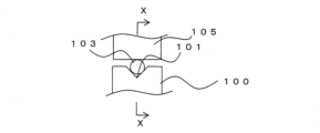
- FIG. 14A is a front view showing a state in which the optical fiber 103 is arranged in the guide portion 100
- FIG. 14B is a cross-sectional view taken along line XX of FIG. 14A.
- the optical fiber 103 is arranged in the V-groove 101 of the guide portion 100, is held by the guide portion 100 by being pressed from above by a clamp 105, and faces another optical fiber (not shown). do.
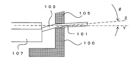
- the optical fibers are aligned by the holder 107 holding the optical fibers 103 and the guide section 100 so that the axial centers Y of the opposing optical fibers 103 are aligned with each other.
- the optical fibers 103 facing each other are butted against each other, arranged between a pair of electrodes, and an electric discharge is generated between the electrodes, whereby the optical fibers 103 can be fusion-spliced.
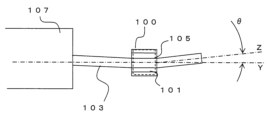
- the axial center of the holder 107 and the axial center of the guide portion 100 may deviate from each other due to the positional accuracy of each part and the bending tendency of the optical fiber 103 .
- the clamp 105 presses the optical fiber 103 along the V-groove 101, and the axial center of the optical fiber 103 is V-shaped on the side facing the other optical fibers. It can be substantially the same as the axis of the groove 101 .
- the rigidity of the optical fiber 103 is stronger than the pressing force of the clamp 105, as shown in FIG. , is shifted by an angle ⁇ in the height direction. That is, the axial center of the optical fiber 103 and the facing direction of the optical fiber 103 do not match.
- FIG. 15A is a plan view showing a state in which the optical fiber 103 is arranged in the guide section 100.
- FIG. As described above, it is desirable that the axis Y of the V-groove 101 in the holder 107 and the guide portion 100 match, but as shown in FIG. be. Also in this case, the axial center Z of the optical fiber 103 is shifted horizontally by an angle ⁇ with respect to the facing direction (Y in the figure) of the optical fibers 103 .
- FIG. 16 is a conceptual diagram showing a state in which the tapered optical fiber 103a is arranged in the V-groove 101 of the guide portion 100. As shown in FIG.
- the tip position of the optical fiber 103a can be aligned by a conventional method, but the axial center Z of the optical fiber 103a is , with respect to the facing direction of the optical fibers 103a by an angle ⁇ .
- the tip positions of the optical fibers facing each other can be aligned, loss increases unless the axial centers of the optical fibers are arranged on a straight line.
- the present invention has been made in view of such problems, and an object of the present invention is to provide a fusion splicer or the like capable of accurately connecting optical waveguide members.
- a first invention is a fusion splicer capable of connecting an optical waveguide member and an optical fiber, comprising a pair of guide portions for positioning the optical waveguide member and the optical fiber so as to face each other. and a pair of electrodes arranged to face each other in a direction substantially perpendicular to the facing direction of the pair of guide portions, wherein at least one of the guide portions is inclined in a direction to cancel the inclination of the optical waveguide member.
- the fusion splicer is characterized in that it is possible to hold the optical waveguide member in a state of being held.
- At least one of the guide portions may have an inclination angle adjustment mechanism capable of adjusting an inclination angle with respect to the opposing direction.
- a control unit may be provided that acquires tilt angle information of the optical waveguide member from the image of the optical waveguide member and controls the tilt angle adjustment mechanism.
- the tilt angle adjustment mechanism may be capable of adjusting at least the tilt angle with respect to the facing direction when viewed from the axial direction of the electrodes.
- the tilt angle adjustment mechanism may be capable of adjusting at least the tilt angle with respect to the facing direction in plan view.
- the tilt angle adjustment mechanism may be capable of independently adjusting the tilt angle with respect to the facing direction when viewed from the axial direction of the electrode and the tilt angle with respect to the facing direction in plan view.
- the tilt angle adjusting mechanism may be capable of adjusting the tilt angle by rotating the guide section to move it in an arc.
- a position adjustment mechanism for aligning the tip position of the optical waveguide member or the optical fiber may be provided, and the position adjustment mechanism and the tilt angle adjustment mechanism may be independently controllable.
- the position adjustment mechanism is arranged on one of the guide portions, and the tilt angle adjustment mechanism is arranged on the other guide portion.
- the tilt angle adjusting mechanism may be arranged on each of the pair of guide portions.
- the optical waveguide member may be an optical fiber having a tapered shape in which the diameter becomes smaller toward the tip.
- the optical waveguide member may be held in a state in which the guide portion is inclined at an angle larger than the taper angle of the optical waveguide member with respect to the facing direction.
- the inclination of the guide portion is 3 degrees or less with respect to the facing direction.
- the guide portion can hold the optical waveguide member in a state inclined in a direction that cancels the inclination of the optical waveguide member, even if the axial direction of the optical waveguide member is inclined, , the axial direction of the optical waveguide member can be aligned with the facing direction of the optical fibers. Therefore, the axial centers of the optical waveguide member and the optical fiber facing each other can be arranged on a straight line.
- the guide portion can be adjusted to an appropriate tilt angle according to the optical waveguide member.
- the tilt angle adjusting mechanism can adjust the tilt angle with respect to the facing direction when viewed from the axial direction of the electrodes, it is possible to adjust the tilt angle when the axes of the holder and the guide section are misaligned in the height direction, Even when the optical waveguide member has a tapered shape, the axial direction can be aligned with the opposing direction.
- the tilt angle adjustment mechanism if at least the tilt angle with respect to the facing direction in plan view can be adjusted, even when the horizontal axis of the holder and the guide part is misaligned, the axial direction can be adjusted to the facing direction. can be matched.
- the tilt angle adjustment mechanism can adjust the tilt angle by rotating the guide portion in an arc shape, it is possible to adjust the angle even for minute tilts in a stepless manner.
- the mechanism in each guide portion can be made smaller.
- the optical waveguide member can also be applied to an optical fiber having a tapered shape in which the diameter becomes smaller toward the tip. It can also be applied when held in a state of being tilted at a large angle. At this time, the inclination of the guide portion with respect to the opposing direction of the guide portion can be 3 degrees or less.
- a second invention is a method for connecting an optical waveguide member and an optical fiber using the fusion splicer according to the first invention, wherein the optical waveguide member is arranged in at least one guide portion, and the optical waveguide member and the optical fiber are opposed to each other, the abutting portion is arranged between the electrodes, and the optical waveguide member and the optical fiber are fused by electric discharge.
- the optical waveguide member may be a bundle fiber in which a plurality of optical fiber core wires are bundled and has a tapered shape in which the diameter becomes narrower toward the tip.
- the optical waveguide member and the optical fiber can be fusion-spliced with high precision by aligning their axial centers.
- optical waveguide member is a bundled optical fiber, it can be fusion-spliced in the same manner as a single-core optical fiber.
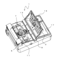
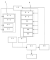
- FIG. 2 is a perspective view showing the fusion splicer 1; 4 is a configuration diagram showing a control mechanism for the operation of the guide section 5 of the fusion splicer 1.
- FIG. FIG. 4 is an enlarged schematic view of the vicinity of the guide portion 5;
- FIG. 4 is an enlarged schematic view of the vicinity of the guide portion 5;
- FIG. 25 is a conceptual diagram of an image 25;
- FIG. 2 is a conceptual front view of a state in which an optical fiber 23 is arranged in a guide portion 5;
- FIG. 2 is a conceptual side view of a state in which an optical fiber 23 is arranged in a guide portion 5;
- FIG. 4 is a conceptual diagram of a method for measuring the tilt of the optical fiber 23;
- FIG. 10 is a diagram showing another tilt adjustment method of the optical fiber 23;
- FIG. 4 is a configuration diagram showing another control mechanism for the operation of the guide section 5 of the fusion splicer 1; The side view which shows the bundle fiber 23a.
- FIG. 9A is a cross-sectional view taken along line LL of FIG. 9A. MM line sectional view of FIG. 9A.
- FIG. 4 is a conceptual diagram showing a fused state of the end cap 29; 4 is a conceptual diagram showing an inclination angle adjusting mechanism 19 of the guide portion 5.
- FIG. 4 is a conceptual diagram showing an inclination angle adjusting mechanism 19 of the guide portion 5.
- FIG. 4 is a conceptual diagram showing an inclination angle adjusting mechanism 19 of the guide portion 5.
- FIG. 4 is a conceptual diagram showing an inclination angle adjusting mechanism 19 of the guide portion 5.
- FIG. 4 is a conceptual diagram showing an inclination angle adjusting mechanism 19 of the guide portion 5.
- FIG. 4 is a conceptual diagram showing an
- FIG. 4 is a configuration diagram showing another operation control mechanism of the guide section 5 of the fusion splicer 1.
- FIG. 4 is a conceptual diagram showing an inclination angle adjusting mechanism 19a of the guide portion 5.
- FIG. 4 is a conceptual diagram showing an inclination angle adjusting mechanism 19a of the guide portion 5.
- FIG. 4 is a front view showing a state in which the optical fiber 103 is installed in the guide section 100 by a conventional method; XX line sectional view of FIG. 14A.
- FIG. 4 is a conceptual diagram showing a case in which a conventional holder 107 and a guide portion 100 are misaligned from each other in the height direction.
- FIG. 4 is a plan view showing a state in which the optical fiber 103 is installed in the guide section 100 by a conventional method;
- FIG. 4 is a conceptual diagram showing a case where a conventional holder 107 and a guide part 100 are misaligned in the horizontal direction.
- FIG. 2 is a conceptual diagram showing a state in which a tapered optical fiber 103a is installed in a conventional guide section 100;
- FIG. 1 is a perspective view showing the fusion splicer 1
- FIG. 2 is a configuration diagram showing a mechanism for controlling the operation of the guide section 5 of the fusion splicer 1.
- FIG. 1 is a perspective view showing the fusion splicer 1
- FIG. 2 is a configuration diagram showing a mechanism for controlling the operation of the guide section 5 of the fusion splicer 1.
- FIG. 1 is a perspective view showing the fusion splicer 1
- FIG. 2 is a configuration diagram showing a mechanism for controlling the operation of the guide section 5 of the fusion splicer 1.
- FIG. 1 connection of an optical waveguide member having a tapered shape in which the diameter becomes smaller toward the tip will be described.
- the optical waveguide member refers to a member including an optical fiber and having a function of guiding light.
- an optical fiber is used as the optical waveguide member. That is, an example of connecting a pair of optical fibers having a tapered shape will be described as the connection of an optical waveguide
- the fusion splicer 1 includes a holder mounting portion 11 on which a holder for holding an optical fiber is mounted, a pair of guide portions 5 for positioning the pair of optical fibers so as to face each other, and a direction in which the pair of optical fibers face each other ( A pair of electrodes 7 facing each other in a direction substantially perpendicular to the facing direction of the pair of guide portions 5, a lid portion 3, an operation portion 15 for operating the fusion splicer 1, and various information are displayed.
- a display unit 17 and the like are provided. Note that the operation unit 15 and the display unit 17 may be integrated by using a touch panel as the display unit 17 .
- the optical fiber is held in the V groove on the guide portion 5.
- the lid portion 3 is rotatable around the rotating shaft 9 .
- a clamp 13 is provided on the rear surface of the lid portion 3 , and when the lid portion 3 is closed, the tip of the clamp 13 is positioned at a position corresponding to the position of the optical fiber on the guide portion 5 . That is, a pair of optical fibers can be held facing each other at the respective guide portions 5 by a pair of clamps 13 provided on the back surface of the lid portion 3 .
- the clamp 13 may be arranged independently of the lid portion 3 without being provided on the lid portion 3 .
- the pair of guide portions 5 are provided with a tilt drive portion 31, a rotation drive portion 32, and a transport drive portion 33, and at least one of the guide portions 5 further has a tip position of the optical fiber.
- An X-direction drive 34 and a Y-direction drive 35 are provided for alignment. Note that the X-direction driving section 34 and the Y-direction driving section 35 may be arranged on both guide sections 5 .
- the rotation driving unit 32 is required, but the rotational alignment is unnecessary. In that case, the rotation drive section 32 is not necessarily required.
- the fusion splicer 1 connects a pair of optical fibers by fusion.
- An optical fiber is held by a pair of holders (not shown), and the holders are placed on the holder placement section 11 .
- the lid portion 3 By closing the lid portion 3 in this state, the optical fiber is held in the guide portion 5 .
- the tips of the pair of optical fibers held by the guide section 5 are transported between the pair of electrodes 7 by the transport driving section 33 .
- An X-direction imaging unit 36 and a Y-direction imaging unit 37 are arranged below the electrodes 7 .
- the X-direction imaging section 36 and the Y-direction imaging section 37 can capture images from the sides near the tip of the optical fiber from different directions.
- the X-direction imaging section 36 and the Y-direction imaging section 37 can image the position of the tip of the optical fiber.
- Information obtained by each imaging unit can be processed by the image processing unit 38 and displayed on the display unit 17 . Further, the obtained image information is processed by the arithmetic processing section 39 and the operation of the guide section 5 is controlled by the control section 30 .
- the optical fibers are aligned by automatically or manually moving the guide unit 5 in each direction so that the tip positions of the optical fibers are aligned, and the tips of the optical fibers are faced to face each other.
- a butt is positioned between the electrodes.
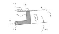
- 3A is a conceptual diagram showing a state in which the tapered optical fiber 23 is arranged in the V groove 21 of the guide portion 5.
- FIG. It should be noted that illustration of the clamp 13 and the holder is omitted in the following description.
- the axis of the optical fiber 23 (B in the figure) is positioned at a predetermined angle ( ⁇ 1 in the figure) with respect to the opposing direction (A in the figure) of the opposing optical fibers. deviate.
- a pair of guide portions 5 are arranged on the guide portion installation portion 6, respectively, and each of the guide portions 5 is adjusted by the tilt angle adjustment mechanism 19 (tilt driving portion 31 (see FIG. 2)). The inclination angle with respect to the installation portion 6 can be adjusted.
- a hinge-like structure is shown as the tilt angle adjustment mechanism 19 for the sake of simplicity, but the tilt angle adjustment mechanism 19 is not particularly limited, and a gonio stage or the like that rotates in an arc without changing its position can be used. It is possible to apply a mechanism that can only perform Details of the tilt angle adjusting mechanism 19 will be described later.
- FIG. 3B is a diagram showing a state in which the tilt angle adjustment mechanism 19 is operated and the guide portion 5 is tilted by an angle ⁇ 2 with respect to the guide portion setting portion 6.
- FIG. 3B is a diagram showing a state in which the tilt angle adjustment mechanism 19 is operated and the guide portion 5 is tilted by an angle ⁇ 2 with respect to the guide portion setting portion 6.
- the tilt angle adjustment mechanism 19 rotates in a horizontal direction (perpendicular to the paper surface) substantially perpendicular to each of the installation direction of the optical fiber 23 (vertical direction in the drawing) and the facing direction of the optical fiber 23 (horizontal direction in the drawing).
- the guide part 5 can be rotated by the shaft.
- a conventional method can be applied to the moving mechanism in the X direction and the moving mechanism in the Y direction. That is, the moving mechanism in the X direction and the moving mechanism in the Y direction can move the guide portion 5 in parallel in each direction. At this time, it is desirable that the tilt angle adjustment mechanism 19 can adjust the tilt angle of the guide portion 5 independently of the movement mechanism in the X direction and the movement mechanism in the Y direction. That is, in the case of having a position adjustment mechanism for aligning the tip position of the optical fiber, it is desirable that the position adjustment mechanism (parallel movement mechanism) and the tilt angle adjustment mechanism can be controlled independently.
- the movement and rotation in each direction may be simultaneously controlled by expanding and contracting each cylinder, and the tip position and tilt angle of the optical fiber may be adjusted at the same time.
- the position adjustment and the tilt angle adjustment may be controlled completely independently, compared to the case of simultaneously controlling the movement and rotation in each direction by controlling the expansion and contraction of each cylinder like a hexapod. Even if an error occurs in the position adjustment, this error can be finely corrected only by the position adjustment mechanism, and in this case, the influence on the tilt angle can be reduced, which is preferable.
- the tapered optical fiber 23 is arranged in the V-groove 21 of the guide portion 5 .
- One of the optical fibers may be a normal optical fiber with the same diameter. That is, the tapered optical fiber 23 is arranged in at least one of the guide portions 5 . In this manner, the tapered optical fibers 23 can be connected to each other, or the tapered optical fiber 23 and a normal optical fiber can be connected.
- FIG. 4 is a conceptual diagram showing an image 25 captured by the X-direction imaging unit 36 or the Y-direction imaging unit 37, for example.
- the imaging unit can image the tip of the optical fiber 23 .
- the image processing unit 38 and the arithmetic processing unit 39 can acquire the tapered angles ⁇ 3 and ⁇ 4 near the tip of each optical fiber 23 captured by image analysis.
- the image processing unit 38 can binarize the image, detect the boundary line of the outer shape of the optical fiber 23, and the arithmetic processing unit 39 can calculate the angle of the obtained straight line.
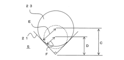
- FIG. 5A is a conceptual front view of a state in which the optical fiber 23 is arranged in the guide portion 5
- FIG. 5(b) is a conceptual side view.
- half of ⁇ 3 in FIG. 4 is assumed to be ⁇ 5 in FIG. 5B.
- the depth of the optical fiber 23, which gradually decreases toward the tip, is arranged in the V-groove 21 depending on the position.
- the inclination angle of the axis when the optical fiber 23 is arranged in the V-groove 21 of the guide portion 5 can be calculated.
- the image of the tip of the optical fiber 23 is acquired by the imaging unit, the taper angle information of the optical fiber 23 is acquired by the image processing unit 38 and the arithmetic processing unit 39, and the optical fiber 23 is obtained from the taper angle information. 23 can be calculated.
- the control unit 30 can control the tilt angle adjustment mechanism 19 (tilt driving unit 31) to tilt the guide unit 5 in the opposite direction so as to cancel the tilt angle of the axis of the optical fiber 23.
- FIG. At this time, by making the inclination angle of the V-groove 21 (guide portion 5) holding the optical fiber 23 larger than the taper angle ⁇ 5 of the optical fiber 23, the axial direction of the optical fiber 23 is set in the opposite direction. , or the angle difference with the opposing direction can be reduced. In this way, it is possible to fuse the tapered optical fiber with a simple structure with high precision and with reduced splicing loss.
- the adjustment of the tilt angle of the guide section 5 may be performed manually by operating the operation section 15 while viewing the image on the display section 17 instead of the automatic adjustment by the control section 30 . Further, instead of obtaining the taper angle of the optical fiber 23 based on the image and calculating the inclination angle of the axis of the optical fiber 23 from the taper angle, the inclination angle of the axis may be calculated directly from the image.
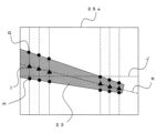
- FIG. 6 is a conceptual diagram of an image 25a captured by the imaging unit.
- the image 25a is an image captured from the side of the optical fiber 23, for example. That is, the image 25a is obtained such that the vertical direction of the image 25a coincides with the vertical direction of the guide portion 5 (the vertical direction in FIG. 3A). Although only the tip of one optical fiber is shown, the same applies to the other optical fiber.
- the optical fiber 23 is arranged at predetermined intervals in the facing direction of the optical fiber 23 (the direction of the straight line J in the figure).
- the positions of the upper boundary (G in the figure) and the lower boundary (H in the figure) are detected, and the midpoint (I in the figure) is recognized as the center position of the optical fiber 23 .
- the arithmetic processing unit 39 can connect this center position to the facing direction of the optical fiber 23 to calculate the axial direction of the optical fiber 23 (the direction of the straight line K in the figure). That is, it is possible to calculate the inclination angle between the facing direction of the optical fiber 23 (straight line J in the drawing) and the axial direction of the optical fiber 23 (straight line K in the drawing).
- the tilt angle of the axis may be calculated based on the image of the optical fiber 23 captured by at least one of the X-direction imaging section 36 and the Y-direction imaging section 37 .
- the inclination angle adjustment mechanism 19 can adjust the inclination angle of the guide portion 5 according to the taper angle of the optical fiber 23 . If the taper angle of the optical fiber 23 is known in advance, the angle of the guide portion 5 may be slanted in advance according to that angle. In this case, as shown in FIG. 7, a spacer 27 may be sandwiched under the guide portion 5 to change the angle of the guide portion 5 .
- the taper angle when the taper angle is known in advance, it is possible to hold the optical fiber 23 in a state in which at least one of the guide portions 5 is tilted in a direction that cancels the tilt due to the tapered shape of the optical fiber 23.
- the tilt angle adjustment mechanism may not be used.
- at least one of the guide portions 5 has an inclination angle adjustment mechanism 19 capable of adjusting the inclination angle.
- the tilt angle adjustment mechanism 19 tilt drive section 31
- the tilt angle adjustment mechanism 19 tilt drive section 31
- one guide portion 5 is provided with a position adjustment mechanism (X-direction drive portion 34, Y-direction drive portion 35), and the other guide portion 5 is provided with a tilt angle adjustment mechanism (tilt drive portion 31). ) may be placed.
- a position adjustment mechanism X-direction drive portion 34, Y-direction drive portion 35
- a tilt angle adjustment mechanism tilt drive portion 31
- the inclination angle adjustment mechanism 19 is arranged only in one of the guide portions 5, when the tapered optical fibers 23 are arranged in the respective guide portions 5, the one guide portion 5 is connected to the respective optical fibers. 23 can be tilted by the sum of the tilt angles.
- the adjustable range of the tilt angle by the tilt angle adjustment mechanism 19 is restricted to a predetermined value or less.
- a predetermined value or less For example, in the range of about 15 mm, which is the distance from the holder to the electrode 7, if the optical fiber with the largest outer diameter of 800 ⁇ m has a tapered shape in which the tip is 0 ⁇ m (i.e., isosceles triangle), The taper angle in this case is approximately 3 degrees. That is, assuming that the taper angle of the optical fiber is 3 degrees at maximum, it is possible to correspond to almost all optical fibers.
- the tilt angle adjustment range of the guide portion 5 is desirably 3 degrees or less at maximum, and more desirably 1.5 degrees or less.
- the tapered optical fiber 23 can be fusion-spliced with the axial center aligned on a straight line. Therefore, an increase in transmission loss can be suppressed.
- the tilt angle of the guide unit 5 is adjusted to an appropriate tilt angle according to the taper angle of each optical fiber 23. It is possible.
- the guide portion 5 is automatically adjusted to an appropriate angle by setting the optical fiber 23 and closing the lid portion 3. can be adjusted.
- At least one of the guide portions 5 has an inclination angle adjustment mechanism 19 capable of adjusting the inclination angle, it is possible to connect the tapered optical fibers 23 to each other. By providing the adjustment mechanism 19, the inclination angle of each guide portion 5 can be reduced.
- the tapered optical waveguide member to be fused may be not only a single optical fiber but also a bundle fiber in which a plurality of optical fibers are bundled.
- 9A is a side view of a bundle fiber 23a in which a plurality of tapered optical fibers 23 are bundled
- FIG. 9B is a cross-sectional view taken along line LL of FIG. 9A
- FIG. 9C is a cross-sectional view taken along line MM of FIG. 9A. It is a line sectional view.
- the bundle fiber 23a is an optical fiber in which a plurality of optical fibers 23 are bundled and integrated by adhesion or the like.
- the overall outer diameter (diameter of the circumscribed circle) of the bundle fiber 23a also tapers toward the tip.
- the number of optical fibers 23 forming the bundle fiber 23a is not limited to the illustrated example. Further, the optical fibers 23 forming the bundle fiber 23a may not all have the same diameter, and may not all be tapered fibers.
- the optical fiber to be fusion-spliced by the fusion splicer 1 may be a single optical fiber 23 having a tapered shape, or a bundle fiber in which a plurality of optical fibers 23 are bundled.
- FIG. 10 is a conceptual diagram when the end cap 29 as an optical waveguide member is fused to the end of the optical fiber 23b.
- the end cap 29 is connected to the input end of the optical fiber or the like, and when the laser light is coupled to the optical fiber, the heat effect and damage to the input end of the optical fiber can be reduced by coupling through the end cap. It becomes possible.
- the end cap 29 has a tapered shape on the side connected to the optical fiber.
- the guide portion 5 is inclined so as to correspond to the tapered shape of a part of the end cap 29, and the ends of the optical fiber 23b and the end cap 29 are aligned with each other.
- the optical fiber 23b to be connected may have substantially the same diameter up to the tip, or may have a tapered shape.
- the guide portion 5 holding the optical fiber 23b may also be inclined corresponding to the tapered shape.
- At least one of the optical waveguide members has a tapered shape in which the outer diameter decreases toward the tip.
- FIG. can also be applied to adjust axial misalignment of the optical fiber due to axial misalignment in the height direction.
- FIG. 11A is a schematic diagram showing the tilt angle adjusting mechanism 19 as seen from the axial direction of the electrode.
- the guide section 5 is installed on the guide section installation section 6 .
- the guide part 5 is rotatable on the guide part setting part 6, but in this embodiment, an example in which the guide part setting part 6 is rotated by the rotation shaft 41 is shown.
- a spring 43 and a direct-acting motor 45 are arranged behind the rotary shaft 41 (left side in the drawing).
- the guide portion setting portion 6 receives a force in a downward pulling direction due to the elastic force of the spring 43 . That is, the guide portion installation portion 6 receives force in the counterclockwise direction about the rotating shaft 41 by the spring 43 .
- the direct-acting motor 45 pushes up the guide portion installation portion 6 . That is, the guide portion setting portion 6 receives force in the opposite direction (clockwise direction) to the spring 43 by the direct-acting motor 45 .
- the guide portion setting portion 6 when the guide portion setting portion 6 is pushed up by the direct-acting motor 45 (in the direction of the arrow N in the figure), the guide portion 5 rotates clockwise around the rotating shaft 41 together with the guide portion setting portion 6 . (in the direction of arrow O in the figure). That is, the axial direction of the guide portion 5 (V groove) can be tilted downward.
- the tilt angle adjustment mechanism 19 adjusts the tilt angle in the height direction (vertical direction in the drawing) with respect to the facing direction of the guide portion 5 (horizontal direction in the drawing) at least when viewed from the axial direction of the electrode. Adjustable. Note that the tilt angle adjusting mechanism is not limited to the illustrated example. Further, in the position adjustment in the X direction and the Y direction, it is sufficient to move the entire tilt angle adjustment mechanism.
- the tilt angle adjustment mechanism of the guide portion 5 may include both a height direction tilt drive portion 31a and a horizontal direction tilt drive portion 31b.
- the position adjustment mechanism (the X-direction drive section 34 and the Y-direction drive section 35) is arranged on one of the guide sections 5, but may be arranged on both.
- the tilt drive section may be arranged only on one of the guide sections 5 .
- only the horizontal tilt driving section 31b may be arranged.
- a mechanism similar to the tilt angle adjustment mechanism 19 shown in FIG. 11A can be applied as the height direction tilt drive unit 31a.
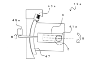
- the horizontal tilt driving section 31b for example, an inclination angle adjusting mechanism 19a as shown in FIGS. 13A and 13B can be applied.
- 13A and 13B are plan views seen from above (clamp side), and the guide portion 5 is indicated by dotted lines.
- the tilt angle adjustment mechanism 19 a has the guide section setting section 6 fixed to the goniometer stage 47 .
- the goniometer stage 47 can move in an arc around the rotary shaft 41a.
- the rotating shaft 41a is arranged at a position corresponding to the V-groove of the guide portion 5, for example. Therefore, the V-groove of the guide portion 5 can change only the direction without changing the position in the horizontal direction.
- a spring 43 a is connected to the goniometer stage 47 .
- the guide portion setting portion 6 receives a force in a direction of pulling back upward in the drawing due to the elastic force of the spring 43a. That is, the guide portion setting portion 6 receives a force in the clockwise direction in the figure about the rotating shaft 41a by the spring 43a.
- the direct-acting motor 45a pushes down a portion of the guide portion setting portion 6 (an arm connected to the guide portion setting portion 6) downward in the figure. That is, the guide portion setting portion 6 receives force in the opposite direction (counterclockwise direction) to the spring 43a by the direct-acting motor 45a.
- the tilt angle adjustment mechanism 19a can adjust the tilt angle in the horizontal direction (vertical direction in the drawing) with respect to the opposing direction (horizontal direction in the drawing) of the guide portion 5 at least in plan view.
- the tilt angle adjusting mechanism includes a tilt angle adjusting mechanism 19 that can adjust the tilt angle with respect to the facing direction of the guide portion 5 when viewed from the axial direction of the electrode, and a tilt angle adjusting mechanism 19 that can adjust the tilt angle with respect to the facing direction of the guide portion 5 in plan view. It is desirable that the adjustable tilt angle adjusting mechanism 19a can be adjusted independently.
- the tilt angle adjusting mechanisms 19 and 19a can adjust the tilt angle by rotating the guide portion 5 in an arc in each direction (height direction and horizontal direction) perpendicular to each other. be. Therefore, the tilt angle in each direction can be adjusted steplessly and accurately.
- the imaging unit acquires images from the respective directions of the tip of the optical fiber, and the image processing unit 38 and the arithmetic processing unit 39 , the tilt angle information of the optical fiber can be obtained.
- the control unit 30 automatically or manually controls the tilt angle adjustment mechanisms 19 and 19a (the height direction tilt drive unit 31a and the horizontal direction tilt drive unit 31b) so that the optical fiber
- the guide portion 5 may be tilted in the opposite direction so as to cancel the tilt angle of the axis of .
- Rotation drive section 33 ??Conveyance driving unit 34 ??X-direction driving unit 35 ??Y-direction driving unit 36 ??X-direction imaging unit 37 ??Y-direction imaging unit 38 ??Image processing unit 39 ............
Landscapes
- Physics & Mathematics (AREA)
- General Physics & Mathematics (AREA)
- Optics & Photonics (AREA)
- Engineering & Computer Science (AREA)
- Plasma & Fusion (AREA)
- Mechanical Coupling Of Light Guides (AREA)
Priority Applications (2)
| Application Number | Priority Date | Filing Date | Title |
|---|---|---|---|
| CN202280060771.2A CN117916640A (zh) | 2021-09-08 | 2022-09-06 | 熔接机、光纤的连接方法 |
| JP2023546942A JPWO2023038019A1 (https=) | 2021-09-08 | 2022-09-06 |
Applications Claiming Priority (2)
| Application Number | Priority Date | Filing Date | Title |
|---|---|---|---|
| JP2021-145920 | 2021-09-08 | ||
| JP2021145920 | 2021-09-08 |
Publications (1)
| Publication Number | Publication Date |
|---|---|
| WO2023038019A1 true WO2023038019A1 (ja) | 2023-03-16 |
Family
ID=85507648
Family Applications (1)
| Application Number | Title | Priority Date | Filing Date |
|---|---|---|---|
| PCT/JP2022/033367 Ceased WO2023038019A1 (ja) | 2021-09-08 | 2022-09-06 | 融着機、光ファイバの接続方法 |
Country Status (3)
| Country | Link |
|---|---|
| JP (1) | JPWO2023038019A1 (https=) |
| CN (1) | CN117916640A (https=) |
| WO (1) | WO2023038019A1 (https=) |
Cited By (1)
| Publication number | Priority date | Publication date | Assignee | Title |
|---|---|---|---|---|
| CN121386092A (zh) * | 2025-12-12 | 2026-01-23 | 天津艾洛克通讯设备科技有限公司 | 一种具有变位交叉扇形运行调芯机构的空芯光纤熔接机 |
Citations (10)
| Publication number | Priority date | Publication date | Assignee | Title |
|---|---|---|---|---|
| JPH02273705A (ja) * | 1989-04-15 | 1990-11-08 | Fujikura Ltd | 光ファイバの軸線合せ装置 |
| JPH06347660A (ja) * | 1993-06-02 | 1994-12-22 | Sumitomo Electric Ind Ltd | 光ファイバの融着接続装置 |
| JPH0743549A (ja) * | 1993-07-29 | 1995-02-14 | Sumitomo Electric Ind Ltd | 光ファイバの調心装置およびその調心方法 |
| JP2004233505A (ja) * | 2003-01-29 | 2004-08-19 | Moritex Corp | 面合せ装置及び面合せ方法 |
| JP2005189813A (ja) * | 2003-12-02 | 2005-07-14 | Fujikura Ltd | 光ファイバの接続方法及び接続構造 |
| JP2006323347A (ja) * | 2005-04-19 | 2006-11-30 | Fujikura Ltd | 光部品の調心装置、光部品の製造方法 |
| JP2012088733A (ja) * | 2003-09-19 | 2012-05-10 | Itf Technologies Optiques Inc-Itf Optical Technologies Inc | 多モードファイバを含むオプティカルカプラ、およびその製造方法 |
| US20180164507A1 (en) * | 2016-12-14 | 2018-06-14 | Bae Systems Information And Electronic Systems Integration Inc. | Infrared fiber combiner |
| JP2019536989A (ja) * | 2016-09-30 | 2019-12-19 | 3エスエーイー テクノロジーズ インク | 多軸相対位置決めステージ |
| CN111077608A (zh) * | 2019-12-24 | 2020-04-28 | 北京航天控制仪器研究所 | 一种用于光纤放大器的多功能光纤组合器件及其制作方法 |
-
2022
- 2022-09-06 JP JP2023546942A patent/JPWO2023038019A1/ja active Pending
- 2022-09-06 WO PCT/JP2022/033367 patent/WO2023038019A1/ja not_active Ceased
- 2022-09-06 CN CN202280060771.2A patent/CN117916640A/zh active Pending
Patent Citations (10)
| Publication number | Priority date | Publication date | Assignee | Title |
|---|---|---|---|---|
| JPH02273705A (ja) * | 1989-04-15 | 1990-11-08 | Fujikura Ltd | 光ファイバの軸線合せ装置 |
| JPH06347660A (ja) * | 1993-06-02 | 1994-12-22 | Sumitomo Electric Ind Ltd | 光ファイバの融着接続装置 |
| JPH0743549A (ja) * | 1993-07-29 | 1995-02-14 | Sumitomo Electric Ind Ltd | 光ファイバの調心装置およびその調心方法 |
| JP2004233505A (ja) * | 2003-01-29 | 2004-08-19 | Moritex Corp | 面合せ装置及び面合せ方法 |
| JP2012088733A (ja) * | 2003-09-19 | 2012-05-10 | Itf Technologies Optiques Inc-Itf Optical Technologies Inc | 多モードファイバを含むオプティカルカプラ、およびその製造方法 |
| JP2005189813A (ja) * | 2003-12-02 | 2005-07-14 | Fujikura Ltd | 光ファイバの接続方法及び接続構造 |
| JP2006323347A (ja) * | 2005-04-19 | 2006-11-30 | Fujikura Ltd | 光部品の調心装置、光部品の製造方法 |
| JP2019536989A (ja) * | 2016-09-30 | 2019-12-19 | 3エスエーイー テクノロジーズ インク | 多軸相対位置決めステージ |
| US20180164507A1 (en) * | 2016-12-14 | 2018-06-14 | Bae Systems Information And Electronic Systems Integration Inc. | Infrared fiber combiner |
| CN111077608A (zh) * | 2019-12-24 | 2020-04-28 | 北京航天控制仪器研究所 | 一种用于光纤放大器的多功能光纤组合器件及其制作方法 |
Cited By (1)
| Publication number | Priority date | Publication date | Assignee | Title |
|---|---|---|---|---|
| CN121386092A (zh) * | 2025-12-12 | 2026-01-23 | 天津艾洛克通讯设备科技有限公司 | 一种具有变位交叉扇形运行调芯机构的空芯光纤熔接机 |
Also Published As
| Publication number | Publication date |
|---|---|
| JPWO2023038019A1 (https=) | 2023-03-16 |
| CN117916640A (zh) | 2024-04-19 |
Similar Documents
| Publication | Publication Date | Title |
|---|---|---|
| US6034718A (en) | Method and apparatus for observing tip portion of optical fibers butting each other | |
| US6467973B2 (en) | Optical fiber fusion splicer | |
| EP4330625B1 (en) | Method and system for measurement of fiber curvature | |
| JP2002328253A (ja) | 定偏波光ファイバの融着接続方法 | |
| JP2005518566A (ja) | PMファイバの調整(alignment) | |
| JP2012242599A (ja) | 光ファイバ判別方法及び光ファイバの融着接続方法 | |
| EP0142062A1 (fr) | Machine automatique de soudage en bout de deux fibres optiques | |
| JP2013054116A (ja) | マルチコアファイバの結合方法 | |
| WO2023038019A1 (ja) | 融着機、光ファイバの接続方法 | |
| EP2669723B1 (en) | Fusion splicing apparatus and fusion splicing method thereof | |
| US7168864B2 (en) | Fusion splicing method and fusion splicer for different-diameter optical fibers | |
| JP2846594B2 (ja) | 光基板の端面の平行度の調整装置 | |
| US12392964B2 (en) | Optical fiber fusion splicer and optical fiber fusion splicing method | |
| US7712981B2 (en) | Compact, active alignment fusion splicer with automatic view-angle compensation | |
| US20240280753A1 (en) | Fusion splicer, and method for connecting optical fiber | |
| JP7407697B2 (ja) | 融着機 | |
| JP2015055788A (ja) | 光伝送路の位置合わせ方法、位置合わせ装置、及び位置合わせプログラム | |
| JP2005099362A (ja) | 光ファイバの融着接続装置と融着接続方法 | |
| JP3237728B2 (ja) | 多心光ファイバ心線接続装置 | |
| JP3273489B2 (ja) | 光ファイバのコア軸合せ方法 | |
| JP2636987B2 (ja) | 多心光ファイバ心線接続装置 | |
| CN203658625U (zh) | 校准系统 | |
| JP3166802B2 (ja) | 多心光ファイバ心線の接続装置 | |
| JP4028493B2 (ja) | 光ファイバの軸合せ装置及び光ファイバ融着接続装置。 | |
| JPH11230865A (ja) | 光コネクタ付き光ファイバアレイの光学特性測定方法及び測定装置 |
Legal Events
| Date | Code | Title | Description |
|---|---|---|---|
| 121 | Ep: the epo has been informed by wipo that ep was designated in this application |
Ref document number: 22867341 Country of ref document: EP Kind code of ref document: A1 |
|
| WWE | Wipo information: entry into national phase |
Ref document number: 2023546942 Country of ref document: JP |
|
| WWE | Wipo information: entry into national phase |
Ref document number: 202280060771.2 Country of ref document: CN |
|
| NENP | Non-entry into the national phase |
Ref country code: DE |
|
| 122 | Ep: pct application non-entry in european phase |
Ref document number: 22867341 Country of ref document: EP Kind code of ref document: A1 |