WO2023037881A1 - 溶融金属めっき鋼帯の製造方法 - Google Patents
溶融金属めっき鋼帯の製造方法 Download PDFInfo
- Publication number
- WO2023037881A1 WO2023037881A1 PCT/JP2022/032019 JP2022032019W WO2023037881A1 WO 2023037881 A1 WO2023037881 A1 WO 2023037881A1 JP 2022032019 W JP2022032019 W JP 2022032019W WO 2023037881 A1 WO2023037881 A1 WO 2023037881A1
- Authority
- WO
- WIPO (PCT)
- Prior art keywords
- steel strip
- gas
- nozzle
- molten metal
- splash
- Prior art date
- Legal status (The legal status is an assumption and is not a legal conclusion. Google has not performed a legal analysis and makes no representation as to the accuracy of the status listed.)
- Ceased
Links
Images






Classifications
-
- C—CHEMISTRY; METALLURGY
- C23—COATING METALLIC MATERIAL; COATING MATERIAL WITH METALLIC MATERIAL; CHEMICAL SURFACE TREATMENT; DIFFUSION TREATMENT OF METALLIC MATERIAL; COATING BY VACUUM EVAPORATION, BY SPUTTERING, BY ION IMPLANTATION OR BY CHEMICAL VAPOUR DEPOSITION, IN GENERAL; INHIBITING CORROSION OF METALLIC MATERIAL OR INCRUSTATION IN GENERAL
- C23C—COATING METALLIC MATERIAL; COATING MATERIAL WITH METALLIC MATERIAL; SURFACE TREATMENT OF METALLIC MATERIAL BY DIFFUSION INTO THE SURFACE, BY CHEMICAL CONVERSION OR SUBSTITUTION; COATING BY VACUUM EVAPORATION, BY SPUTTERING, BY ION IMPLANTATION OR BY CHEMICAL VAPOUR DEPOSITION, IN GENERAL
- C23C2/00—Hot-dipping or immersion processes for applying the coating material in the molten state without affecting the shape; Apparatus therefor
- C23C2/003—Apparatus
-
- C—CHEMISTRY; METALLURGY
- C23—COATING METALLIC MATERIAL; COATING MATERIAL WITH METALLIC MATERIAL; CHEMICAL SURFACE TREATMENT; DIFFUSION TREATMENT OF METALLIC MATERIAL; COATING BY VACUUM EVAPORATION, BY SPUTTERING, BY ION IMPLANTATION OR BY CHEMICAL VAPOUR DEPOSITION, IN GENERAL; INHIBITING CORROSION OF METALLIC MATERIAL OR INCRUSTATION IN GENERAL
- C23C—COATING METALLIC MATERIAL; COATING MATERIAL WITH METALLIC MATERIAL; SURFACE TREATMENT OF METALLIC MATERIAL BY DIFFUSION INTO THE SURFACE, BY CHEMICAL CONVERSION OR SUBSTITUTION; COATING BY VACUUM EVAPORATION, BY SPUTTERING, BY ION IMPLANTATION OR BY CHEMICAL VAPOUR DEPOSITION, IN GENERAL
- C23C2/00—Hot-dipping or immersion processes for applying the coating material in the molten state without affecting the shape; Apparatus therefor
- C23C2/14—Removing excess of molten coatings; Controlling or regulating the coating thickness
- C23C2/16—Removing excess of molten coatings; Controlling or regulating the coating thickness using fluids under pressure, e.g. air knives
- C23C2/18—Removing excess of molten coatings from elongated material
- C23C2/20—Strips; Plates
-
- C—CHEMISTRY; METALLURGY
- C23—COATING METALLIC MATERIAL; COATING MATERIAL WITH METALLIC MATERIAL; CHEMICAL SURFACE TREATMENT; DIFFUSION TREATMENT OF METALLIC MATERIAL; COATING BY VACUUM EVAPORATION, BY SPUTTERING, BY ION IMPLANTATION OR BY CHEMICAL VAPOUR DEPOSITION, IN GENERAL; INHIBITING CORROSION OF METALLIC MATERIAL OR INCRUSTATION IN GENERAL
- C23C—COATING METALLIC MATERIAL; COATING MATERIAL WITH METALLIC MATERIAL; SURFACE TREATMENT OF METALLIC MATERIAL BY DIFFUSION INTO THE SURFACE, BY CHEMICAL CONVERSION OR SUBSTITUTION; COATING BY VACUUM EVAPORATION, BY SPUTTERING, BY ION IMPLANTATION OR BY CHEMICAL VAPOUR DEPOSITION, IN GENERAL
- C23C2/00—Hot-dipping or immersion processes for applying the coating material in the molten state without affecting the shape; Apparatus therefor
- C23C2/04—Hot-dipping or immersion processes for applying the coating material in the molten state without affecting the shape; Apparatus therefor characterised by the coating material
- C23C2/06—Zinc or cadmium or alloys based thereon
-
- C—CHEMISTRY; METALLURGY
- C23—COATING METALLIC MATERIAL; COATING MATERIAL WITH METALLIC MATERIAL; CHEMICAL SURFACE TREATMENT; DIFFUSION TREATMENT OF METALLIC MATERIAL; COATING BY VACUUM EVAPORATION, BY SPUTTERING, BY ION IMPLANTATION OR BY CHEMICAL VAPOUR DEPOSITION, IN GENERAL; INHIBITING CORROSION OF METALLIC MATERIAL OR INCRUSTATION IN GENERAL
- C23C—COATING METALLIC MATERIAL; COATING MATERIAL WITH METALLIC MATERIAL; SURFACE TREATMENT OF METALLIC MATERIAL BY DIFFUSION INTO THE SURFACE, BY CHEMICAL CONVERSION OR SUBSTITUTION; COATING BY VACUUM EVAPORATION, BY SPUTTERING, BY ION IMPLANTATION OR BY CHEMICAL VAPOUR DEPOSITION, IN GENERAL
- C23C2/00—Hot-dipping or immersion processes for applying the coating material in the molten state without affecting the shape; Apparatus therefor
- C23C2/34—Hot-dipping or immersion processes for applying the coating material in the molten state without affecting the shape; Apparatus therefor characterised by the shape of the material to be treated
- C23C2/36—Elongated material
- C23C2/40—Plates; Strips
-
- B—PERFORMING OPERATIONS; TRANSPORTING
- B05—SPRAYING OR ATOMISING IN GENERAL; APPLYING FLUENT MATERIALS TO SURFACES, IN GENERAL
- B05C—APPARATUS FOR APPLYING FLUENT MATERIALS TO SURFACES, IN GENERAL
- B05C11/00—Component parts, details or accessories not specifically provided for in groups B05C1/00 - B05C9/00
- B05C11/02—Apparatus for spreading or distributing liquids or other fluent materials already applied to a surface ; Controlling means therefor; Control of the thickness of a coating by spreading or distributing liquids or other fluent materials already applied to the coated surface
- B05C11/06—Apparatus for spreading or distributing liquids or other fluent materials already applied to a surface ; Controlling means therefor; Control of the thickness of a coating by spreading or distributing liquids or other fluent materials already applied to the coated surface with a blast of gas or vapour
-
- C—CHEMISTRY; METALLURGY
- C23—COATING METALLIC MATERIAL; COATING MATERIAL WITH METALLIC MATERIAL; CHEMICAL SURFACE TREATMENT; DIFFUSION TREATMENT OF METALLIC MATERIAL; COATING BY VACUUM EVAPORATION, BY SPUTTERING, BY ION IMPLANTATION OR BY CHEMICAL VAPOUR DEPOSITION, IN GENERAL; INHIBITING CORROSION OF METALLIC MATERIAL OR INCRUSTATION IN GENERAL
- C23C—COATING METALLIC MATERIAL; COATING MATERIAL WITH METALLIC MATERIAL; SURFACE TREATMENT OF METALLIC MATERIAL BY DIFFUSION INTO THE SURFACE, BY CHEMICAL CONVERSION OR SUBSTITUTION; COATING BY VACUUM EVAPORATION, BY SPUTTERING, BY ION IMPLANTATION OR BY CHEMICAL VAPOUR DEPOSITION, IN GENERAL
- C23C2/00—Hot-dipping or immersion processes for applying the coating material in the molten state without affecting the shape; Apparatus therefor
- C23C2/14—Removing excess of molten coatings; Controlling or regulating the coating thickness
- C23C2/16—Removing excess of molten coatings; Controlling or regulating the coating thickness using fluids under pressure, e.g. air knives
-
- C—CHEMISTRY; METALLURGY
- C23—COATING METALLIC MATERIAL; COATING MATERIAL WITH METALLIC MATERIAL; CHEMICAL SURFACE TREATMENT; DIFFUSION TREATMENT OF METALLIC MATERIAL; COATING BY VACUUM EVAPORATION, BY SPUTTERING, BY ION IMPLANTATION OR BY CHEMICAL VAPOUR DEPOSITION, IN GENERAL; INHIBITING CORROSION OF METALLIC MATERIAL OR INCRUSTATION IN GENERAL
- C23C—COATING METALLIC MATERIAL; COATING MATERIAL WITH METALLIC MATERIAL; SURFACE TREATMENT OF METALLIC MATERIAL BY DIFFUSION INTO THE SURFACE, BY CHEMICAL CONVERSION OR SUBSTITUTION; COATING BY VACUUM EVAPORATION, BY SPUTTERING, BY ION IMPLANTATION OR BY CHEMICAL VAPOUR DEPOSITION, IN GENERAL
- C23C2/00—Hot-dipping or immersion processes for applying the coating material in the molten state without affecting the shape; Apparatus therefor
- C23C2/14—Removing excess of molten coatings; Controlling or regulating the coating thickness
- C23C2/16—Removing excess of molten coatings; Controlling or regulating the coating thickness using fluids under pressure, e.g. air knives
- C23C2/18—Removing excess of molten coatings from elongated material
Definitions
- the present invention relates to a method for manufacturing a hot-dip metal plated steel strip.
- Hot-dip galvanized steel sheets which are a type of hot-dip galvanized steel sheet, are widely used in fields such as building materials, automobiles, and home appliances. In these applications, hot-dip galvanized steel sheets are required to have excellent appearance. Here, since the appearance after painting is strongly affected by surface defects such as coating thickness unevenness, flaws, and adhesion of foreign matter, it is important that hot-dip galvanized steel sheets do not have surface defects.
- a steel strip as a metal strip annealed in a continuous annealing furnace in a reducing atmosphere passes through the snout and is introduced into the molten metal bath in the plating tank. Then, the steel strip is pulled up above the molten metal bath through sink rolls and support rolls in the molten metal bath. Thereafter, a wiping gas is blown onto the surface of the steel strip from gas wiping nozzles arranged on both sides of the steel strip to scrape off surplus molten metal adhered to the surface of the steel strip and pulled up. Thereby, the adhesion amount of the molten metal (hereinafter also referred to as the basis weight) is adjusted.
- the gas wiping nozzle is normally configured wider than the width of the steel strip in order to handle various widths of the steel strip and to cope with misalignment in the width direction when the steel strip is pulled up. It extends outside from the end.
- the molten metal that falls downward due to the turbulence of the jet that collides with the steel strip scatters around, solidifies during the scatter, and adheres to the steel strip as fine metal powder, the so-called splash. Defects (splash defects) are generated due to this, resulting in deterioration of the surface quality of the steel strip.
- the steel strip threading speed should be increased in order to increase the production volume.
- the wiping gas pressure must be set to a higher pressure in order to control the coating weight within a certain range. As a result, the splash increases a lot and good quality cannot be maintained.
- Patent Document 1 describes a method for preventing molten metal droplets from adhering to the strip surface during molten metal plating.
- a metal plate is installed between the wiping gas supply main pipe and the wiping nozzle.
- a filter is installed along the steel plate between the wiping gas supply main and the alloying furnace.
- the plating metal splash generated on the surface of the plating bath is removed by a filter when it goes around the outside of the wiping nozzle and heads for the steel sheet after wiping, so that the steel sheet is splashed. prevent sticking.
- Patent Document 2 discloses a method of preventing adhesion of splashes to the plated steel strip by providing a rectifying plate that protrudes behind the wiping nozzle and a weir in the upper front part of the wiping nozzle.
- Patent Document 3 proposes a method of suppressing the splash defect by installing a side nozzle above the wiping nozzle and blowing gas from the side nozzle to the gas turbulence in the gas-gas collision area of the wiping gas.
- Patent Document 1 it has been found that the method disclosed in Patent Document 1 is insufficiently effective in preventing the occurrence of splash defects. That is, if the mesh of the filter is increased, the effect of the filter is lost. On the other hand, if the mesh of the filter is made small, the splash around the outside of the filter will not adhere to the strip surface. However, the splash directly entering between the filter and the metal plate without going around the back of the wiping nozzle is difficult to be discharged out of the filter. Therefore, the effect of preventing the occurrence of splash defects is insufficient.
- Patent Document 2 cannot prevent the splash flying upward around the back of the wiping nozzle from adhering to the plated steel strip.
- the splash (metal powder) deposited on the straightening plate protruding behind the wiping nozzle during operation is re-scattered due to changes in the wiping gas flow due to changes in wiping conditions (wiping gas pressure, nozzle height, etc.). will come to This phenomenon becomes apparent as time passes, and it has been found that the method disclosed in Patent Document 2 cannot stably prevent splash adhesion.
- the present invention has been made in view of the above circumstances, and an object of the present invention is to provide a method for manufacturing a hot-dip metal plated steel strip that suppresses the occurrence of splash defects by suppressing the adhesion of splashes to the steel strip.
- Means of the present invention for solving the above problems are as follows. [1] A steel strip is continuously immersed in a molten metal bath, and a slit-shaped gas extending wider than the steel strip along the width direction of the steel strip pulled up from the molten metal bath. A pair of gas wiping nozzles having an injection port and arranged on both sides of the steel strip are provided with a pair of gas wiping nozzles.
- the horizontal axis represents the angle ⁇ (°) formed by the direction of injection of the gas injected from the gas injection port and the horizontal plane, the distance D (mm) between the tip of the gas injection port and the steel strip, and the width of the gas injection port
- each of the pair of gas wiping nozzles has a nozzle header, and an upper nozzle member and a lower nozzle member connected to the nozzle header; the tip portion of the upper nozzle member and the tip portion of the lower nozzle member face each other in parallel in a cross-sectional view perpendicular to the width direction of the steel strip to form the gas injection port;
- adhesion of splashes to the steel strip can be suppressed, and a hot-dip metal plated steel strip in which the generation of splash defects is suppressed can be produced.
- the direction of splash is limited by operating the gas wiping nozzle within a predetermined range with respect to the direction of travel of the steel strip.
- the occurrence of splash defects is suppressed, and a hot-dip metal plated steel strip with excellent surface quality can be stably produced.
- FIG. 1 is a schematic diagram showing a schematic configuration of a continuous hot-dip metal plating facility equipped with a gas wiping nozzle according to one embodiment of the present invention.
- FIG. 2 is a schematic diagram showing a schematic configuration of a gas wiping nozzle used in the continuous hot dip metal plating equipment shown in FIG.
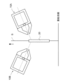
- FIG. 3 is a schematic diagram showing the scattering direction of the splash.
- FIG. 4 is a schematic diagram illustrating each configuration according to one embodiment of the present invention.
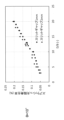
- FIG. 5 shows the result of investigating the angle ⁇ formed by the gas injection direction and the horizontal plane and the splash defect occurrence rate in one embodiment of the present invention.
- FIG. 1 is a schematic diagram showing a schematic configuration of a continuous hot-dip metal plating facility equipped with a gas wiping nozzle according to one embodiment of the present invention.
- FIG. 2 is a schematic diagram showing a schematic configuration of
- FIG. 7 is a schematic diagram showing the velocity distribution of the jet discharged from the gas wiping nozzle.
- FIG. 11 shows the quotient D/ It is the figure which showed the range of B.
- FIG. FIG. 12 is a schematic diagram (side view) showing an embodiment in which a baffle plate is arranged.
- FIG. 13 is a schematic diagram (top view) showing an embodiment when a baffle plate is arranged.
- FIG. 14 is an enlarged view showing the vicinity of one width direction end of the steel strip S in FIG. 13 .
- FIG. 15 is an enlarged view of the vicinity of the tip of the gas wiping nozzle.
- FIG. 1 shows a schematic configuration of a continuous hot-dip metal plating facility equipped with a gas wiping nozzle according to one embodiment of the present invention.
- the continuous hot-dip metal plating equipment 1 shown in FIG. 1 continuously adheres the molten metal to the surface of the steel strip S by immersing the steel strip S as a metal strip in a molten metal bath 4 made of molten metal. After that, it is a facility for making the molten metal adhere to a predetermined amount.
- the continuous hot-dip metal plating equipment 1 includes a snout 2, a plating tank 3, a sink roll 5, and a support roll 6.
- the snout 2 is a member that defines the space through which the steel strip S passes.
- the snout 2 is a member having a rectangular cross section perpendicular to the traveling direction of the steel strip S, and its upper end is connected to, for example, the exit side of the continuous annealing furnace, and its lower end is a molten metal bath 4 stored in the plating tank 3. immersed in In this embodiment, the steel strip S annealed in a continuous annealing furnace in a reducing atmosphere passes through the snout 2 and is continuously introduced into the molten metal bath 4 in the plating bath 3 . After that, the steel strip S is lifted upward from the molten metal bath 4 through sink rolls 5 and support rolls 6 in the molten metal bath 4 .
- a pair of gas wiping nozzles 10A and 10B are arranged above the molten metal bath 4 so as to face each other with the steel strip S interposed therebetween.
- the nozzle 10A blows gas toward the steel strip S from a gas injection port 11 (nozzle slit) extending in the width direction of the steel strip at its tip to measure the coating amount on the surface of the steel strip. adjust.
- the pair of nozzles 10A and 10B scrape off surplus molten metal, adjust the coating weight on both sides of the steel strip S, and make the coating weight uniform in the width direction and the lengthwise direction of the steel strip S. be.
- the nozzle 10A is normally configured to be longer than the width of the steel strip so as to accommodate various widths of the steel strip and to cope with positional deviation in the width direction when the steel strip is pulled up, and extends from the end of the steel strip in the width direction to the outside. extended.
- the nozzle 10A has a nozzle header 12, and an upper nozzle member 13A and a lower nozzle member 13B connected to the nozzle header 12.
- the tip portions of the upper and lower nozzle members 13A and 13B face each other in parallel in a cross-sectional view perpendicular to the width direction of the steel strip S to form the gas injection ports 11 (nozzle slits) (parallel portions in FIG. 2). ).
- the gas injection port 11 extends in the width direction of the steel strip S.
- the gas injection port 11 has a slit-like shape that extends wider than the steel strip S along the width direction of the steel strip S.
- the vertical cross-sectional shape of the nozzle 10A is tapered toward the tip.
- the thickness of the tips of the upper and lower nozzle members 13A and 13B may be about 1 to 3 mm.
- the width (opening width) B (slit gap) of the gas injection port is not particularly limited, but can be about 0.5 to 3.0 mm.
- a gas supplied from a gas supply mechanism passes through the interior of the nozzle header 12, further passes through the gas flow path defined by the upper and lower nozzle members 13A and 13B, and is injected from the gas injection port 11 to form the steel strip S is sprayed on the surface of
- the other nozzle 10B also has a similar configuration.
- the pressure inside the nozzle header 12 is measured by a pressure gauge (not shown). The pressure inside the nozzle header 12 can be adjusted by the output of the gas supply mechanism.
- FIG. 15 is an enlarged view showing the vicinity of the tip of the nozzle 10A.
- the tapered portion on the outer surface side of the upper nozzle member 13A is called the outer tapered portion of the upper nozzle member 13A (outer taper portion 131A)
- the tapered portion on the outer surface side of the lower nozzle member 13B is called the lower nozzle member 13B.
- the angle formed by the outer tapered portion 131A of the upper nozzle member 13A and the outer tapered portion 131B of the lower nozzle member 13B is called the outer shape angle of the nozzle 10A (outer shape angle ⁇ ).
- pressurized gas is applied to the surface of the steel strip that is continuously pulled up from the hot-dip metal plating bath from gas wiping nozzles arranged opposite to both sides of the steel strip.
- the thickness of the deposited metal is controlled by spraying the band surface.
- the molten metal scatters, and solidifies during the scatter to form metal powder (splash), which adheres to the steel strip, causing a problem of degrading the surface quality of the steel strip.
- splash defects refer to defects caused by splashes adhering to the steel plate.
- jets gas jets
- FIG. 3(a) jets (gas jets) discharged from opposing nozzles collide with each other near the edge of the steel sheet, causing the jets to vibrate, thereby melting the steel sheet.
- Defects that occur when a metal liquid film is torn off solidifies in the process of scattering the torn off liquid film as droplets, becomes a solid (metal powder), and adheres to the steel plate.
- the inventors first examined the scattering direction of the splash (metal powder) with a high-speed camera in order to study the method of suppressing the splash defect.
- the nozzle angle ⁇ the angle between the gas injection direction and the horizontal plane
- the splash is as shown in Fig. 3(b). It was found that the particles were scattered over a wide area upwards and downwards.
- the operator finely adjusts the nozzle downward (nozzle angle: 0 to 2°) based on experience.
- the fine adjustment of the nozzle angle depends on the skill of the operator, the splash defect varies depending on the timing of operation and is not stable. So, I thought that if I tilted the nozzle downward a lot, the situation would change dramatically and the splash defect would be improved.
- a 10-ton coil with a plate width of 1000 mm and a plate thickness of 1 mm was threaded at a speed of 100 mpm (meters per minute).
- the amount of zinc deposited at the center of the width of the plate was 50 ⁇ 5 g/m 2 .
- the pressure indicated by the pressure gauge attached to the nozzle header was adjusted so that After that, the splash defect occurrence rate was examined with a defect meter installed on the CGL output side, and the correlation with the nozzle angle was investigated.
- the jet collides with the plate edge even under the condition that the nozzle tilted downward and the nozzle angle is increased.
- the flow rate of the gas directed toward the bath surface (downward) is greater than the flow rate of the gas directed upward, it is considered that the splash scatters downward preferentially.
- the splash directed upward from the nozzle was suppressed. It is presumed that this reduced the scattering range of the splash and reduced the splash defect.
- the nozzle angle ⁇ is in the range of 10 to 60°, it is considered that the splash defect occurrence rate is close to 0 as a result of the splash not scattering upwards from the nozzle.
- the gap between the nozzle and the steel plate becomes smaller as shown in FIG. That is, the space between the outer tapered portion of the upper nozzle member 13A and the steel strip S becomes narrower, and the upward gas flow is obstructed by colliding in the vicinity of the plate edge portion. Vortices are more likely to occur between them.
- the splash that scatters from the plate edge part scatters in various directions due to the flow of the generated vortex.
- the reason for the increase in splash defects is considered to be that the splash that was scattered above the nozzle due to the influence of this vortex adhered to the steel plate.
- the lower limit of the nozzle angle ⁇ is 10° because the effect of reducing splash defects appears in the range of 10° or more.
- the amount of zinc deposited varies depending on the impact pressure gradient due to the collision of the gas with the steel strip S and the shear force generated in the zinc film due to the collision of the gas with the steel strip S.
- the impact pressure gradient becomes smaller.
- the collision pressure gradient is the gradient of the collision pressure in the direction corresponding to the direction of the slit gap B when the jet discharged from the nozzle collides with the object (steel strip).
- a larger gas flow rate is required with the same nozzle-to-steel distance (interval), which requires a compressor with a large capacity, which increases the construction cost.
- a suitable range for the nozzle angle ⁇ is 15° ⁇ 45°.
- ⁇ 10° the effect of reducing the splash defect is exhibited, but by setting the nozzle angle ⁇ to 15° or more, it is possible to further suppress the decrease in the collision pressure at the edge of the steel plate. That is, when the nozzle angle ⁇ is small, the jets discharged from the opposed nozzles collide with the outside of the edge of the plate, vibrating the jets and reducing the pressure acting on the edge of the steel plate.
- the nozzle angle ⁇ is small, the jets discharged from the opposed nozzles collide with the outside of the edge of the plate, vibrating the jets and reducing the pressure acting on the edge of the steel plate.
- the nozzle angle ⁇ by setting the nozzle angle ⁇ to 15° or more, it is possible to suppress the decrease in the pressure acting on the end portion of the steel sheet.
- the nozzle angle ⁇ When the impact pressure at the edge of the steel plate decreases, the effect of scraping off surplus molten metal weakens.
- the lower limit of the preferable range of the nozzle angle ⁇ is 15°.
- the upper limit of the preferable range of the nozzle angle ⁇ is 45°.
- the phenomenon in which zinc splashes from the bath surface is called bath surface splash. When the bath surface splash occurs, problems may occur such as defects in the steel sheet and deterioration of the surrounding environment of the facility.
- the characteristics of the impinging jet are organized by D/B, which is the distance (interval) D from the tip of the nozzle (the tip of the gas injection port) to the impingement plate (steel strip) divided by the slit gap B. be.
- D/B the distance (interval) D from the tip of the nozzle (the tip of the gas injection port) to the impingement plate (steel strip) divided by the slit gap B.
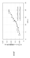
- the splash defect occurrence rate can be arranged by D/B regardless of the slit gap B. Also, the splash defect occurrence rate differs depending on the nozzle angle. From this, it was found that controlling the nozzle angle and D/B, which is the distance between the nozzle and the steel plate divided by the slit gap, is important for suppressing the splash defect.
- the nozzle-steel plate distance is small, the nozzle may collide with the steel plate due to plate warpage, so the lower limit of D/B is 3.
- the turbulence of the jet increases (the stability of the jet deteriorates) due to the disappearance of the potential core, thereby increasing the splash defects. Therefore, the upper limit of D/B is 10 when the nozzle angle ⁇ is 10° (FIG. 8).
- the upper limit of D/B is 12 within the range of 30° ⁇ 60°.
- FIG. 11 summarizes the above ranges with respect to D/B and ⁇ .
- D/B 3 (Formula 1)
- D/B 0.1 ⁇ +9 (Formula 2)
- D/B 12 (Formula 3)
- ⁇ 10 (Formula 4)
- ⁇ 60 (Formula 5)
- a preferable range of D/B is D/B ⁇ 10.
- D/B ⁇ 10 By setting D/B ⁇ 10, it is possible to suppress the decrease in the collision pressure at the edge of the steel plate caused by the collision of the jets discharged from the opposed nozzles outside the edge of the plate, and the edge overcoat. Defects can be suppressed. That is, when D/B increases, the turbulence of the jet increases due to the disappearance of the potential core, and the vibration of the jet that occurs when the jets discharged from opposing nozzles collide with each other on the outside of the plate edge also increases.
- the above range is preferable in order to suppress the decrease in the collision pressure at the edge of the sheet width that is generated by this.
- the pressure (gas pressure) inside the nozzle header 12 is 2 to 70 kPa in the proper range of D/B obtained by dividing the nozzle angle ⁇ and the nozzle-steel plate distance by the slit gap for preventing splash defects. is preferred. More preferably, the pressure is 3 kPa or more. Further, it is more preferable that the pressure is 60 kPa or less. This is because if the pressure inside the nozzle header 12 is less than 2 kPa, the turbulence of the jet flow increases until it collides with the steel plate, and splash defects are likely to occur. This is because if the pressure inside the nozzle header 12 exceeds 70 kPa, the size of the compressor for injecting the gas will increase and the equipment cost will increase, which is not economical.
- the jet velocity of the gas discharged from the nozzle is preferably 100 to 500 m/s. This is because if the flow velocity of the gas discharged from the nozzle is less than 100 m/s, the turbulence of the jet flow becomes large before it collides with the steel plate, and splash defects are likely to occur. This is because if the flow velocity of the gas discharged from the nozzle exceeds 500 m/s, the size of the compressor for injecting the gas is increased and the equipment cost is high, which is not economical.
- the length of the parallel portion of the slit gap formed in the gas injection port 11 is preferably 10 to 40 mm. If the length of the parallel portion of the slit gap is less than 10 mm, the formation of the potential core of the ejected jet is insufficient, and the turbulence of the jet increases before it collides with the steel plate, and splash defects are likely to occur. is. This is because if the length of the parallel portion of the slit gap exceeds 40 mm, the resistance to the flow of gas passing through the slit gap increases and the efficiency of gas injection decreases, requiring excessive power.
- the nozzle tip height defined by the distance between the nozzle tip (the tip of the gas injection port) and the surface of the molten metal (zinc) bath is too low, A vortex is generated, resulting in a wrinkle defect. That is, the flow (backflow) of the molten metal that is scraped off by the gas injected from the nozzle and flows downward on the surface of the steel sheet becomes non-uniform, resulting in wrinkles. Conversely, if the height of the nozzle tip is too high, local solidification of the metal (zinc) begins after the steel strip is pulled upward from the molten metal bath until the wiping gas is blown, resulting in A wrinkle defect occurs.
- the nozzle tip height H (the distance between the tip of the gas injection port and the bath surface of the molten metal bath, see FIG. 4) is preferably 50 mm or more and 700 mm or less. .
- the nozzle tip height H is more preferably over 150 mm (H>150 mm).
- the nozzle tip height H is more preferably less than 550 mm (H ⁇ 550 mm).
- the hot water wrinkles are wavy ripple patterns (wrinkles) that occur on the plated surface of the hot-dip metal plated steel sheet.
- the surface properties of the coating film, particularly the smoothness are impaired when the plated surface is used as the base surface for coating.
- the temperature T (° C.) of the gas (wiping gas) immediately after being injected from the nozzle slit of the gas wiping nozzle 10 is related to the melting point TM (° C.) of the molten metal. It is preferable to control the temperature of the wiping gas so as to satisfy ⁇ 150 ⁇ T ⁇ TM+250. By controlling the temperature T (° C.) of the wiping gas within this range, the cooling and solidification of the molten metal can be suppressed, so that the viscosity unevenness is less likely to occur, and the generation of melt wrinkles can be suppressed.
- the method of raising the temperature of the wiping gas supplied to the gas wiping nozzle 10 is not particularly limited.
- a pair of baffle plates 20 and 21 are arranged on the outer side of both ends of the steel strip S in the width direction, preferably on the extended surface of the steel strip near the ends of the steel strip S in the width direction. is preferred.
- 12 and 13 show side and top views, respectively, of a pair of nozzles 10A, 10B with baffle plates 20, 21 disposed thereon.
- Baffle plates 20, 21 are arranged between the pair of nozzles 10A, 10B. Therefore, the front and back surfaces of the baffle plate face the gas injection ports 11 of the pair of nozzles 10A and 10B.
- the baffle plates 20 and 21 contribute to reducing splash by acting to avoid direct collision between the gases injected from the pair of nozzles 10A and 10B. Accordingly, by arranging the baffle plate, the effect of further suppressing the occurrence of the splash defect is enhanced compared to the above-described embodiment.
- the shape of the baffle plates 20 and 21 is not particularly limited, it is preferable that they are rectangular, two sides of which are preferably arranged parallel to the extending direction of the ends of the steel strip S in the width direction.
- the plate thickness of the baffle plates 20, 21 is preferably 2 to 10 mm. If the plate thickness is 2 mm or more, the baffle plate is less likely to be deformed by the pressure of the wiping gas. If the plate thickness is 10 mm or less, the possibility of contact with the wiping nozzle or thermal deformation is reduced.
- the length of the baffle plates 20 and 21 along the direction of movement of the steel strip S is such that the upper end is above the position where the gas jetted from the pair of nozzles 10A and 10B directly collides, and the lower end is above the bath surface.
- the lower ends of the baffle plates 20, 21 may be arranged to be submerged in the molten metal bath.
- FIG. 14 is an enlarged view showing the vicinity of one width direction end of the steel strip S in FIG.
- the distance E between the widthwise end of the steel strip and the baffle plate is preferably 10 mm or less, more preferably 5 mm or less. This makes it possible to more reliably prevent the direct collision of the opposing jets.
- the distance E is preferably 3 mm or more.
- the material of the baffle plate is not particularly limited. However, in the present embodiment, since the baffle plate is close to the bath surface, top dross and splash may adhere and alloy with the baffle plate to adhere. Moreover, when the baffle plate is immersed in the bath, it is necessary to consider not only the above alloying but also thermal deformation. From this point of view, examples of the material for the baffle plate include an iron plate coated with a boron nitride-based spray that easily repels zinc, and SUS316L that does not easily react with zinc. Furthermore, ceramics such as alumina, silicon nitride, and silicon carbide are desirable because they can suppress both alloying and thermal deformation.
- Hot-dip galvanized steel strips are examples of hot-dip metal-plated steel strips manufactured by applying the gas wiping nozzle and hot-dip metal-plated steel strip manufacturing method according to the present embodiment.
- This hot-dip galvanized steel strip includes both a galvanized steel strip (GI) that is not alloyed after hot-dip galvanizing and a galvanized steel strip that is alloyed (GA).
- GI galvanized steel strip
- GA galvanized steel strip that is alloyed
- the hot-dip metal plated steel strip manufactured by applying the gas wiping nozzle and the hot-dip metal plated steel strip manufacturing method according to the present embodiment is not limited to this, and other molten metals such as aluminum and tin other than zinc It includes all hot dip metal plated steel strips including.
- Example 1 Using the continuous hot dip metal plating equipment 1 having the basic configuration shown in FIG. , hot-dip galvanized steel strips were produced under the conditions shown in Table 1. Further, regarding the gas wiping nozzles 10A and 10B, the width B of the gas injection port 11 is 1 mm. The temperature of the molten zinc bath during the experiment was 460°C, and the gas temperature T at the tip of the gas wiping nozzle was 100°C or 450°C. Further, under the conditions shown in Table 1, the gas pressure of the wiping nozzle (the pressure inside the nozzle header) was adjusted so that the adhesion amount at the center of the width of the strip fell within 50 ⁇ 5 g/m 2 .
- the splash defect incidence rate is the ratio of the length of the steel strip judged to have splash defects to the length of the steel strip passed through the inspection process on the delivery side of the CGL (continuous hot dip galvanizing line), and is 0.10% or less. I passed the test. In addition, the bath surface of the molten zinc bath was visually observed to evaluate the occurrence of bath surface splash.
- Hot-dip galvanized steel sheet with visible wrinkles ⁇ : Hot-dip galvanized steel sheet with no visible hot water wrinkles
- a cut plate was taken from the coil on the CGL output side, and a sample for adhesion amount analysis with a diameter of 48 mm was taken at a position 50 mm inward from the plate width center and the plate width edge.
- the obtained sample was subjected to an adhesion amount analysis, and the results were arranged as an edge overcoat ratio (EOC ratio), which is an increase rate of adhesion amount at the width edge relative to the width center.
- EOC ratio edge overcoat ratio
- the hot water wrinkle evaluation is “ ⁇ ” and the EOC rate is 5.0% or less.
- Table 1 shows the experimental results.
- the conditions of Examples 1 to 22 are as follows: the horizontal axis represents the angle ⁇ (°) formed by the direction of gas injection and the horizontal plane; In the graph drawn with the quotient D/B as the vertical axis, it falls within the range enclosed by the following (formula 1) to (formula 5). That is, invention examples 1 to 22 are examples in which the gas wiping nozzles 10A and 10B were operated within the above range.
- D/B 3 (Formula 1)
- D/B 0.1 ⁇ +9 (Formula 2)
- D/B 12 (Formula 3)
- ⁇ 10 (Formula 4)
- ⁇ 60 (Formula 5)
- the splash defect occurrence rate was 0.10% or less, and the sample was accepted.
- D/B 3 (Formula 1)
- ⁇ 45 (Formula 8)
- Comparative Examples 1 to 16 were out of the range defined by (Equation 1) to (Equation 5), and the splash defect occurrence rate exceeded 0.10% and was rejected. Further, Comparative Examples 14 to 16 are examples in which steel strips were produced under the conditions described in JP-A-2018-9220. Under the conditions of Comparative Examples 14 to 16, the nozzle height was set to 350 mm, so the flow wrinkles were suppressed. Edge overcoat also deteriorated.
- Example 2 As another example of the present invention, a hot-dip galvanized steel strip having a thickness of 1.0 mm and a width of 1200 mm is manufactured using the continuous hot-dip metal plating equipment 1 having the basic configuration shown in FIG. An example will be described.
- the hot-dip galvanized steel strip was produced under the conditions shown in Table 2 by immersing the steel strip S into the hot-dip zinc bath at a threading speed of 0.75-2.16 m/s (45-130 mpm).
- the width B of the gas injection port 11 of the gas wiping nozzles 10A and 10B was 1.0 to 1.4 mm, and the length G of the parallel portion of the slit gap was 30 mm.
- a pair of baffle plates were arranged outside the widthwise end portions of the steel strip S.
- the thickness of the baffle plate is 5 mm
- the distance E between the width direction end of the steel strip and the baffle plate is 5 mm
- the lower end of the baffle plate is positioned 30 mm above the bath surface of the molten zinc bath.
- the baffle plate was placed in The temperature of the molten zinc bath is 460°C
- the gas temperature T at the tip of the gas wiping nozzle is 450°C.
- the gas pressure of the wiping nozzle (internal pressure of the nozzle header) was adjusted so that the adhesion amount at the central portion of the width of the steel strip S was the value shown in Table 2.
- the horizontal axis represents the angle ⁇ (°) formed by the gas injection direction and the horizontal plane, and the quotient D of the distance D (mm) between the steel strip from the tip of the gas injection port and the width B (mm) of the gas injection port.
- the operation was performed within the range surrounded by the above-mentioned (Equation 1) to (Equation 5).
- the distance H between the tip of the gas injection port and the bath surface of the molten zinc bath is in the range of 50 mm or more and 700 mm or less, and the temperature T (° C.) of the gas immediately after injection from the gas wiping nozzle ) was operated under conditions satisfying TM ⁇ 150 ⁇ T ⁇ TM+250 in relation to the melting point TM (° C.) of molten zinc.
- invention examples 23 to 29 had a splash defect occurrence rate of 0.10% or less and passed. Moreover, no bath surface splash occurred, and the EOC rate was 5.0% or less. From the above, it was confirmed that the adhesion of splashes to the steel strip can be suppressed and the hot-dip galvanized steel strip in which the occurrence of splash defects can be suppressed can be produced according to the present example. At the same time, it was confirmed that a hot-dip galvanized steel strip can be produced in which surface quality defects such as wrinkles are prevented, and edge overcoat is suppressed to improve zinc yield.
Landscapes
- Chemical & Material Sciences (AREA)
- Chemical Kinetics & Catalysis (AREA)
- Engineering & Computer Science (AREA)
- Materials Engineering (AREA)
- Mechanical Engineering (AREA)
- Metallurgy (AREA)
- Organic Chemistry (AREA)
- Coating With Molten Metal (AREA)
Priority Applications (8)
| Application Number | Priority Date | Filing Date | Title |
|---|---|---|---|
| CN202280059496.2A CN117897515A (zh) | 2021-09-10 | 2022-08-25 | 熔融金属镀覆钢带的制造方法 |
| JP2022573495A JP7839109B2 (ja) | 2021-09-10 | 2022-08-25 | 溶融金属めっき鋼帯の製造方法 |
| KR1020247007148A KR20240033179A (ko) | 2021-09-10 | 2022-08-25 | 용융 금속 도금 강대의 제조 방법 |
| MX2024002808A MX2024002808A (es) | 2021-09-10 | 2022-08-25 | Metodo para fabricar banda de acero recubierto con metal por inmersion en caliente. |
| EP22867203.6A EP4368741A1 (en) | 2021-09-10 | 2022-08-25 | Molten metal-plated steel strip production method |
| US18/688,060 US20240352569A1 (en) | 2021-09-10 | 2022-08-25 | Method for manufacturing hot-dip metal-coated steel strip |
| AU2022341700A AU2022341700B2 (en) | 2021-09-10 | 2022-08-25 | Method for Manufacturing Hot-Dip Metal-Coated Steel Strip |
| JP2025004469A JP2025063171A (ja) | 2021-09-10 | 2025-01-14 | 溶融金属めっき鋼帯の製造方法 |
Applications Claiming Priority (2)
| Application Number | Priority Date | Filing Date | Title |
|---|---|---|---|
| JP2021-147458 | 2021-09-10 | ||
| JP2021147458 | 2021-09-10 |
Publications (1)
| Publication Number | Publication Date |
|---|---|
| WO2023037881A1 true WO2023037881A1 (ja) | 2023-03-16 |
Family
ID=85506540
Family Applications (1)
| Application Number | Title | Priority Date | Filing Date |
|---|---|---|---|
| PCT/JP2022/032019 Ceased WO2023037881A1 (ja) | 2021-09-10 | 2022-08-25 | 溶融金属めっき鋼帯の製造方法 |
Country Status (8)
| Country | Link |
|---|---|
| US (1) | US20240352569A1 (https=) |
| EP (1) | EP4368741A1 (https=) |
| JP (2) | JP7839109B2 (https=) |
| KR (1) | KR20240033179A (https=) |
| CN (1) | CN117897515A (https=) |
| AU (1) | AU2022341700B2 (https=) |
| MX (1) | MX2024002808A (https=) |
| WO (1) | WO2023037881A1 (https=) |
Citations (8)
| Publication number | Priority date | Publication date | Assignee | Title |
|---|---|---|---|---|
| US3681118A (en) * | 1965-06-08 | 1972-08-01 | Hitachi Ltd | Method of removing excess molten metal coatings by employing low pressure gas streams |
| JPS512055B1 (https=) * | 1967-02-02 | 1976-01-22 | ||
| JPS5134902Y1 (https=) * | 1969-03-14 | 1976-08-28 | ||
| JPH05306449A (ja) | 1992-04-30 | 1993-11-19 | Nkk Corp | 溶融金属メッキ時における溶融金属飛沫のストリップ面への付着防止方法 |
| JP2000328218A (ja) | 1999-05-10 | 2000-11-28 | Kawasaki Steel Corp | 溶融金属めっき方法および装置 |
| JP2014080673A (ja) | 2012-09-25 | 2014-05-08 | Nippon Steel & Sumitomo Metal | スプラッシュ飛散抑制方法及び装置 |
| WO2020039869A1 (ja) * | 2018-08-22 | 2020-02-27 | Jfeスチール株式会社 | 溶融金属めっき鋼帯の製造方法及び連続溶融金属めっき設備 |
| JP2020190005A (ja) * | 2019-05-20 | 2020-11-26 | Jfeスチール株式会社 | 溶融金属めっき鋼帯の製造方法及び連続溶融金属めっき設備 |
Family Cites Families (3)
| Publication number | Priority date | Publication date | Assignee | Title |
|---|---|---|---|---|
| US3865298A (en) * | 1973-08-14 | 1975-02-11 | Atomic Energy Commission | Solder leveling |
| WO2016056178A1 (ja) * | 2014-10-08 | 2016-04-14 | Jfeスチール株式会社 | 連続溶融金属めっき方法および溶融亜鉛めっき鋼帯ならびに連続溶融金属めっき設備 |
| JP6414360B2 (ja) * | 2018-05-25 | 2018-10-31 | Jfeスチール株式会社 | 溶融金属めっき鋼帯の製造方法 |
-
2022
- 2022-08-25 MX MX2024002808A patent/MX2024002808A/es unknown
- 2022-08-25 AU AU2022341700A patent/AU2022341700B2/en active Active
- 2022-08-25 KR KR1020247007148A patent/KR20240033179A/ko active Pending
- 2022-08-25 EP EP22867203.6A patent/EP4368741A1/en active Pending
- 2022-08-25 US US18/688,060 patent/US20240352569A1/en active Pending
- 2022-08-25 WO PCT/JP2022/032019 patent/WO2023037881A1/ja not_active Ceased
- 2022-08-25 JP JP2022573495A patent/JP7839109B2/ja active Active
- 2022-08-25 CN CN202280059496.2A patent/CN117897515A/zh active Pending
-
2025
- 2025-01-14 JP JP2025004469A patent/JP2025063171A/ja not_active Withdrawn
Patent Citations (8)
| Publication number | Priority date | Publication date | Assignee | Title |
|---|---|---|---|---|
| US3681118A (en) * | 1965-06-08 | 1972-08-01 | Hitachi Ltd | Method of removing excess molten metal coatings by employing low pressure gas streams |
| JPS512055B1 (https=) * | 1967-02-02 | 1976-01-22 | ||
| JPS5134902Y1 (https=) * | 1969-03-14 | 1976-08-28 | ||
| JPH05306449A (ja) | 1992-04-30 | 1993-11-19 | Nkk Corp | 溶融金属メッキ時における溶融金属飛沫のストリップ面への付着防止方法 |
| JP2000328218A (ja) | 1999-05-10 | 2000-11-28 | Kawasaki Steel Corp | 溶融金属めっき方法および装置 |
| JP2014080673A (ja) | 2012-09-25 | 2014-05-08 | Nippon Steel & Sumitomo Metal | スプラッシュ飛散抑制方法及び装置 |
| WO2020039869A1 (ja) * | 2018-08-22 | 2020-02-27 | Jfeスチール株式会社 | 溶融金属めっき鋼帯の製造方法及び連続溶融金属めっき設備 |
| JP2020190005A (ja) * | 2019-05-20 | 2020-11-26 | Jfeスチール株式会社 | 溶融金属めっき鋼帯の製造方法及び連続溶融金属めっき設備 |
Also Published As
| Publication number | Publication date |
|---|---|
| AU2022341700A1 (en) | 2024-02-08 |
| AU2022341700B2 (en) | 2025-07-03 |
| JP7839109B2 (ja) | 2026-04-01 |
| JPWO2023037881A1 (https=) | 2023-03-16 |
| US20240352569A1 (en) | 2024-10-24 |
| KR20240033179A (ko) | 2024-03-12 |
| CN117897515A (zh) | 2024-04-16 |
| EP4368741A1 (en) | 2024-05-15 |
| JP2025063171A (ja) | 2025-04-15 |
| MX2024002808A (es) | 2024-04-09 |
Similar Documents
| Publication | Publication Date | Title |
|---|---|---|
| US11866829B2 (en) | Device and method for manufacturing a coated metal strip with improved appearance by adjusting a coating thickness using gas jet wiping | |
| CN100393907C (zh) | 液体擦拭装置 | |
| KR102471806B1 (ko) | 용융 금속 도금 강대의 제조 방법 및 연속 용융 금속 도금 설비 | |
| JP6372527B2 (ja) | 溶融金属めっき鋼帯の製造方法及び連続溶融金属めっき設備 | |
| JP5418550B2 (ja) | 溶融金属めっき鋼帯の製造方法 | |
| WO2023037881A1 (ja) | 溶融金属めっき鋼帯の製造方法 | |
| JP4857906B2 (ja) | 溶融金属めっき鋼帯の製造方法 | |
| JP6500846B2 (ja) | 溶融金属めっき鋼帯の製造方法及び連続溶融金属めっき設備 | |
| KR101532496B1 (ko) | 와이핑 장치 및 이것을 사용한 용융 도금 장치 | |
| WO2023088625A1 (en) | Method for manufacturing a coated metal strip with improved appearance and wiping device therefor | |
| JP6638872B1 (ja) | 溶融金属めっき鋼帯の製造方法及び連続溶融金属めっき設備 | |
| JP6414360B2 (ja) | 溶融金属めっき鋼帯の製造方法 | |
| JP4816105B2 (ja) | 溶融金属めっき鋼帯の製造方法 | |
| JP7111058B2 (ja) | 溶融金属めっき鋼帯の製造方法及び連続溶融金属めっき設備 | |
| JPH11279736A (ja) | 厚目付けに適したガスワイピング方法 | |
| JP5386779B2 (ja) | 溶融めっき鋼板の製造方法及び装置 | |
| JP4765641B2 (ja) | 溶融金属めっき鋼帯の製造方法 | |
| JP6635086B2 (ja) | 溶融金属めっき鋼帯の製造方法 | |
| JPH04285146A (ja) | 連続溶融金属めっき装置 |
Legal Events
| Date | Code | Title | Description |
|---|---|---|---|
| WWE | Wipo information: entry into national phase |
Ref document number: 2022573495 Country of ref document: JP |
|
| 121 | Ep: the epo has been informed by wipo that ep was designated in this application |
Ref document number: 22867203 Country of ref document: EP Kind code of ref document: A1 |
|
| WWE | Wipo information: entry into national phase |
Ref document number: 202417002460 Country of ref document: IN |
|
| WWE | Wipo information: entry into national phase |
Ref document number: 2022341700 Country of ref document: AU Ref document number: AU2022341700 Country of ref document: AU |
|
| ENP | Entry into the national phase |
Ref document number: 2022341700 Country of ref document: AU Date of ref document: 20220825 Kind code of ref document: A |
|
| WWE | Wipo information: entry into national phase |
Ref document number: 2022867203 Country of ref document: EP |
|
| ENP | Entry into the national phase |
Ref document number: 2022867203 Country of ref document: EP Effective date: 20240208 |
|
| WWE | Wipo information: entry into national phase |
Ref document number: 2401001321 Country of ref document: TH |
|
| ENP | Entry into the national phase |
Ref document number: 20247007148 Country of ref document: KR Kind code of ref document: A |
|
| WWE | Wipo information: entry into national phase |
Ref document number: 18688060 Country of ref document: US |
|
| WWE | Wipo information: entry into national phase |
Ref document number: 202280059496.2 Country of ref document: CN |
|
| NENP | Non-entry into the national phase |
Ref country code: DE |