WO2023032618A1 - 通気路用消音器 - Google Patents
通気路用消音器 Download PDFInfo
- Publication number
- WO2023032618A1 WO2023032618A1 PCT/JP2022/030476 JP2022030476W WO2023032618A1 WO 2023032618 A1 WO2023032618 A1 WO 2023032618A1 JP 2022030476 W JP2022030476 W JP 2022030476W WO 2023032618 A1 WO2023032618 A1 WO 2023032618A1
- Authority
- WO
- WIPO (PCT)
- Prior art keywords
- housing
- opening
- muffler
- wall surface
- ventilation path
- Prior art date
- Legal status (The legal status is an assumption and is not a legal conclusion. Google has not performed a legal analysis and makes no representation as to the accuracy of the status listed.)
- Ceased
Links
Images








Classifications
-
- F—MECHANICAL ENGINEERING; LIGHTING; HEATING; WEAPONS; BLASTING
- F24—HEATING; RANGES; VENTILATING
- F24F—AIR-CONDITIONING; AIR-HUMIDIFICATION; VENTILATION; USE OF AIR CURRENTS FOR SCREENING
- F24F13/00—Details common to, or for air-conditioning, air-humidification, ventilation or use of air currents for screening
- F24F13/24—Means for preventing or suppressing noise
-
- F—MECHANICAL ENGINEERING; LIGHTING; HEATING; WEAPONS; BLASTING
- F16—ENGINEERING ELEMENTS AND UNITS; GENERAL MEASURES FOR PRODUCING AND MAINTAINING EFFECTIVE FUNCTIONING OF MACHINES OR INSTALLATIONS; THERMAL INSULATION IN GENERAL
- F16L—PIPES; JOINTS OR FITTINGS FOR PIPES; SUPPORTS FOR PIPES, CABLES OR PROTECTIVE TUBING; MEANS FOR THERMAL INSULATION IN GENERAL
- F16L55/00—Devices or appurtenances for use in, or in connection with, pipes or pipe systems
- F16L55/02—Energy absorbers; Noise absorbers
- F16L55/033—Noise absorbers
-
- F—MECHANICAL ENGINEERING; LIGHTING; HEATING; WEAPONS; BLASTING
- F24—HEATING; RANGES; VENTILATING
- F24F—AIR-CONDITIONING; AIR-HUMIDIFICATION; VENTILATION; USE OF AIR CURRENTS FOR SCREENING
- F24F13/00—Details common to, or for air-conditioning, air-humidification, ventilation or use of air currents for screening
- F24F13/02—Ducting arrangements
-
- G—PHYSICS
- G10—MUSICAL INSTRUMENTS; ACOUSTICS
- G10K—SOUND-PRODUCING DEVICES; METHODS OR DEVICES FOR PROTECTING AGAINST, OR FOR DAMPING, NOISE OR OTHER ACOUSTIC WAVES IN GENERAL; ACOUSTICS NOT OTHERWISE PROVIDED FOR
- G10K11/00—Methods or devices for transmitting, conducting or directing sound in general; Methods or devices for protecting against, or for damping, noise or other acoustic waves in general
- G10K11/16—Methods or devices for protecting against, or for damping, noise or other acoustic waves in general
-
- G—PHYSICS
- G10—MUSICAL INSTRUMENTS; ACOUSTICS
- G10K—SOUND-PRODUCING DEVICES; METHODS OR DEVICES FOR PROTECTING AGAINST, OR FOR DAMPING, NOISE OR OTHER ACOUSTIC WAVES IN GENERAL; ACOUSTICS NOT OTHERWISE PROVIDED FOR
- G10K11/00—Methods or devices for transmitting, conducting or directing sound in general; Methods or devices for protecting against, or for damping, noise or other acoustic waves in general
- G10K11/16—Methods or devices for protecting against, or for damping, noise or other acoustic waves in general
- G10K11/161—Methods or devices for protecting against, or for damping, noise or other acoustic waves in general in systems with fluid flow
-
- G—PHYSICS
- G10—MUSICAL INSTRUMENTS; ACOUSTICS
- G10K—SOUND-PRODUCING DEVICES; METHODS OR DEVICES FOR PROTECTING AGAINST, OR FOR DAMPING, NOISE OR OTHER ACOUSTIC WAVES IN GENERAL; ACOUSTICS NOT OTHERWISE PROVIDED FOR
- G10K11/00—Methods or devices for transmitting, conducting or directing sound in general; Methods or devices for protecting against, or for damping, noise or other acoustic waves in general
- G10K11/16—Methods or devices for protecting against, or for damping, noise or other acoustic waves in general
- G10K11/172—Methods or devices for protecting against, or for damping, noise or other acoustic waves in general using resonance effects
-
- F—MECHANICAL ENGINEERING; LIGHTING; HEATING; WEAPONS; BLASTING
- F24—HEATING; RANGES; VENTILATING
- F24F—AIR-CONDITIONING; AIR-HUMIDIFICATION; VENTILATION; USE OF AIR CURRENTS FOR SCREENING
- F24F13/00—Details common to, or for air-conditioning, air-humidification, ventilation or use of air currents for screening
- F24F13/24—Means for preventing or suppressing noise
- F24F2013/242—Sound-absorbing material
-
- F—MECHANICAL ENGINEERING; LIGHTING; HEATING; WEAPONS; BLASTING
- F24—HEATING; RANGES; VENTILATING
- F24F—AIR-CONDITIONING; AIR-HUMIDIFICATION; VENTILATION; USE OF AIR CURRENTS FOR SCREENING
- F24F13/00—Details common to, or for air-conditioning, air-humidification, ventilation or use of air currents for screening
- F24F13/24—Means for preventing or suppressing noise
- F24F2013/245—Means for preventing or suppressing noise using resonance
Definitions
- the present invention relates to a muffler for an air passage that silences the sound in the air passage.
- Some vents are equipped with silencers that muffle the sound (noise) that passes through the vents.
- An example of such an air passage with a silencer is the duct described in Patent Document 1, for example.
- the duct described in Patent Document 1 has a resonator with an opening provided on the side surface of the duct, and a soundproof cover that covers the resonator.
- a part of the duct, the resonator, and the soundproof cover constitute a muffling structure, and the muffling structure muffles noise propagating through the duct.
- the muffler for air passages can effectively muffle the sound in the high frequency band as well as the sound in the low frequency band.
- the present invention has been made in view of the above circumstances, and solves the problems of the prior art.
- the purpose is to provide a vessel.
- a muffler for an air passage that includes a housing and muffles sound in the air passage, wherein the internal space of the housing constitutes a part of the air passage, and the air passage is formed in the housing.
- an inlet opening positioned at one end of the unit, an outlet opening formed in the housing and positioned at the other end of a portion of the air passage, a sound absorbing member housed inside the housing, and a sound absorbing member provided in the housing , a vibrating portion for reducing sound passing through the airway.
- the inlet opening is formed on one end surface of the inner wall surface of the housing in the first direction, the outlet opening is formed on the other end surface of the inner wall surface of the housing in the first direction, and Among the cross sections, the ratio of the length of the longest side in the contour to the length of the shortest side in the contour is 1.2 or more in the contour of the cross section whose normal direction is the first direction. , a muffler for an air passage according to any one of [1] to [6]. [8] The inlet opening is formed on one end surface of the inner wall surface of the housing in the first direction, and the outlet opening is formed on the other end surface of the inner wall surface of the housing in the first direction.
- the inlet opening is formed on one end surface of the inner wall surface of the housing in the first direction, and the outlet opening is formed on the other end surface of the inner wall surface of the housing in the first direction.
- the length of the housing in a second direction intersecting with is greater than the length of the housing in a third direction intersecting both the first direction and the second direction, each of the inlet opening and the outlet opening being in the second direction ,
- the muffler for air passage according to any one of [1] to [8], which is provided at a position closer to the end of the housing than the center of the housing.
- the inlet opening is formed on one end surface of the inner wall surface of the housing in the first direction
- the outlet opening is formed on the other end surface of the inner wall surface of the housing in the first direction
- a connecting member is connected to at least one of the inlet opening and the outlet opening in the internal space, and a connecting member-side opening connected to at least one of the openings is provided inside the connecting member.
- the inlet opening is formed on one end surface of the inner wall surface of the housing in the first direction
- the outlet opening is formed on the other end surface of the inner wall surface of the housing in the first direction
- the sound absorbing member is , in a second direction that intersects the first direction and in a third direction that intersects both the first direction and the second direction, avoiding the range where the entrance opening exists and the range where the exit opening exists
- the muffler for air passage according to any one of [1] to [12].
- the ventilation path according to [13], wherein the ratio of the area occupied by the sound absorbing member to the volume of the space inside the housing excluding the flow path part is 80% or more in the internal space of the housing. Silencer for.
- the muffler for air passages of the present invention muffles sounds in the low frequency band by vibrating the housing that forms part of the air passages. Further, the sound absorbing member arranged inside the housing can muffle the sound in the high frequency band. As a result, with a relatively compact structure, it is possible to provide a muffler for an air passage that is capable of silencing sound from a low frequency band to a high frequency band.
- FIG. 1 is a cross-sectional view showing the configuration of a muffler for an air passage according to an embodiment of the present invention
- FIG. 1 is a top view showing a muffler for an air passage according to one embodiment of the present invention
- FIG. 1 is a side view showing a silencer for an air passage according to one embodiment of the present invention
- FIG. 3 is a view showing the downstream end face of the airway silencer according to one embodiment of the present invention
- FIG. 10 is a side view of the airway silencer according to the first modification of the present invention
- FIG. 11 is a side view showing a first modified example of the connection member
- FIG. 11 is a side view showing a second modification of the connection member;
- FIG. 4 is a diagram showing the distribution of sound energy and the flow of sound within the housing when ⁇ /4 resonance occurs. 4 is a graph showing the silencing characteristics of the airway muffler.
- FIG. 10 is a diagram showing sound pressure distribution in the housing when resonance occurs in the back space of the connection member; 4 is a graph showing the silencing characteristics measured for each of Example 1 and Comparative Example 1.
- FIG. 10 is a graph showing the silencing characteristics measured for each of Example 2 and Comparative Example 2.
- FIG. 5 is a graph showing the noise reduction characteristics measured for each of Examples 2 and 3.
- FIG. 10 is a graph showing the silencing characteristics measured for each of Example 4 and Comparative Example 3.
- FIG. 5 is a graph showing the noise reduction characteristics measured for each of Examples 2 and 5.
- FIG. FIG. FIG. 10 is a diagram showing sound pressure distribution in the housing when resonance occurs in the back space of the connection member; 4 is a graph showing the silencing characteristics measured for each of Example 1 and Comparative Example 1.
- FIG. 10 is
- FIG. 10 is a graph showing noise reduction characteristics measured for Examples 6 and 7.
- FIG. FIG. 11 is a diagram showing the appearance of silencers according to Examples 8 and 9;
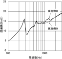
- FIG. 11 is a graph showing noise reduction characteristics measured for Examples 8 and 9;
- FIG. 10 is a diagram showing the relationship between the occupancy rate of the sound absorbing member and the sound pressure of wind noise;
- FIG. 11 is a side view of a muffler for an air passage according to a second modification of the present invention;
- FIG. 2 is a cross-sectional view of a muffler for an air passage according to a second modification of the present invention, corresponding to FIG. 1;
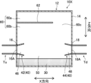
- FIG. 11 is a side view of a muffler for an air passage according to a third modification of the present invention;
- FIG. 3 is a cross-sectional view of a muffler for an air passage according to a third modification of the present invention, corresponding to FIG. 1;
- a numerical range represented using “to” means a range including the numerical values described before and after “to” as lower and upper limits.
- the terms “perpendicular”, “perpendicular” and “parallel” include the range of error that is permissible in the technical field to which the present invention belongs.
- the terms “perpendicular,””perpendicular,” and “parallel” herein mean within ⁇ 10° or less of strictly orthogonal, perpendicular, or parallel, and the like.
- the error from strict orthogonality or parallelism is preferably 5° or less, more preferably 3° or less.
- the meanings of “same”, “identical” and “equal” may include the margin of error generally accepted in the technical field to which the present invention belongs.
- the meanings of “all”, “any” and “all” include the range of errors generally accepted in the technical field to which the present invention belongs, in addition to the case of 100%. for example, 99% or more, 95% or more, or 90% or more.
- “silencing” in the present invention is a concept that includes both sound insulation and sound absorption.
- Sound insulation means shielding sound, in other words, not allowing sound to pass through.
- Sound absorption means reducing reflected sound, and in simple terms it means absorbing sound (sound).
- XYZ directions the three directions orthogonal to each other.
- the X direction corresponds to the first direction of the present invention
- the Z direction corresponds to the second direction of the present invention
- the Y direction corresponds to the third direction of the present invention.
- the side closer to the exhaust port in the air passage will be referred to as the "downstream side”
- the opposite side that is, the side closer to the air supply port will be referred to as the "upstream side”.
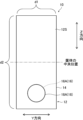
- FIG. 4 is a view showing the downstream end face of the ventilation path muffler 10, and in the figure, the entrance opening 16 that does not appear in the downstream end face is indicated by broken lines.
- the ventilation path silencer 10 is arranged, for example, in the middle of the ventilation path provided inside the equipment or inside the building. That is, as shown in FIG. It is installed in a state sandwiched between it and the ventilation path Td.
- the upstream ventilation path Tu and the downstream ventilation path Td are respectively configured by hoses, pipes, or the like.
- the ventilation path silencer 10 includes a housing 12 as a main component.
- a sound absorbing member 30 and a pair of connecting members 40 are arranged in the internal space of the housing 12, as shown in FIG.
- Each component of the ventilation path silencer 10 will be individually described below.
- the housing 12 is a box-shaped hollow body, and has walls 14 surrounding the internal space of the housing 12 as shown in FIG.
- the housing 12 has a total length in the X direction, a height in the Y direction, and a width in the Z direction.
- the housing 12 of the present embodiment has a flat rectangular parallelepiped shape that is crushed in the Y direction, and has a plurality of (specifically, six) outer wall surfaces 12S.
- the width of the housing 12 (the length in the Z direction) is longer than the height of the housing 12 (the length in the Y direction).
- the ratio of the length of the longest side in the outline to the length of the shortest side in the outline in the outline of the cross section normal to the X direction in the cross section of the housing 12 is 1.2 or more.
- the shortest side corresponds to the height of the housing 12 and its length is equal to the length d1 in FIG.
- the longest side corresponds to the width of housing 12 and its length is equal to length d2 in FIG.
- Each portion of the wall 14 is a plate material with a relatively thin thickness, and forms both ends of the housing 12 in the XYZ directions.
- the material of the wall 14 is not particularly limited, for example, metal material, resin material, reinforced plastic material, carbon fiber, etc. can be used as the material of the wall 14 .
- metal materials include aluminum, titanium, magnesium, tungsten, iron, steel, chromium, chrome molybdenum, nichrome molybdenum, copper, steel galvanized cold commercial (SGCC), and alloys such as stainless steel.
- metal materials such as Examples of resin materials include acrylic resin, polymethyl methacrylate, polycarbonate, polyamideoid, polyarylate, polyetherimide, polyacetal, polyetheretherketone, polyphenylene sulfide, polysulfone, polyethylene terephthalate, polybutylene terephthalate, polyimide, ABS resin (acrylonitrile, flame-retardant ABS resin, butadiene, styrene copolymer synthetic resin), polypropylene, triacetylcellulose (TAC), polypropylene (PP), polyethylene (PE: polyethylene), polystyrene (PS: Polystyrene), ASA (Acrylate Styrene Acrylonitrile) resin, polyvinyl chloride (
- Reinforced plastic materials include carbon fiber reinforced plastics (CFRP) and glass fiber reinforced plastics (GFRP). Further, as the material of the wall 14, natural rubber, chloroprene rubber, butyl rubber, EPDM (ethylene-propylene-diene rubber), silicone rubber, and rubbers including these crosslinked structures can be used.
- the wall 14 is constructed, for example, by arranging a plurality of (specifically, six) plate members in a box shape and joining the plate members adjacent to each other. Alternatively, when the wall 14 is divided into two pieces, each piece may be formed by injection molding or the like, and the wall 14 may be configured by combining the pieces. Also, each portion of the wall 14 forms a flat plate, and two portions of the wall 14 that are opposed to each other are aligned in parallel.
- the outer wall surfaces 12S of the housing 12 formed by the outer surfaces of the walls 14, the outer wall surfaces 12S (XZ plane) located at both ends in the Y direction are the surfaces having the largest area among the outer wall surfaces 12S. , hereinafter referred to as the maximum outer wall surface.
- the outer wall surface 12S of the housing 12 has one or more portions forming a plane (more specifically, a flat surface) including the maximum outer wall surface.
- each part of the wall 14 is made of the same material.
- a portion of the wall 14 (for example, the vibrating portion 20 described later) may be made of a material different from that of the surrounding portion.
- a portion of the wall 14, for example, the vibrating portion 20 may be made of the same material as the surrounding portion but have a plate thickness different from that of the surrounding portion.
- An entrance opening 16 is provided at one end of the wall 14 in the X direction, and an exit opening 18 is provided at the other end. That is, the internal space of the housing 12 constitutes a part of the ventilation path, and the air (wind) that flows into the housing 12 through the inlet opening 16 flows out of the housing 12 through the outlet opening 18. .
- the X direction corresponds to the direction in which air flows in the housing 12, that is, the ventilation direction.
- the inlet opening 16 and the outlet opening 18 are holes penetrating the wall 14 in the X direction and communicating with the internal space of the housing 12 . Further, as shown in FIG. 1, the inlet opening 16 is connected to the upstream air passage Tu, and the outlet opening 18 is connected to the downstream air passage Td. It should be noted that each of the inlet opening 16 and the outlet opening 18 may penetrate the wall 14 parallel to the X direction, or may penetrate the wall 14 obliquely relative to the X direction.
- the boundary position between the entrance opening 16 and the internal space of the housing 12, that is, the inner open end of the entrance opening 16 corresponds to the entrance opening 16A.
- the inlet opening 16A is formed on the upstream end face (in other words, one end face in the X direction) of the inner wall surface of the housing 12 .
- the inlet opening 16A is positioned upstream (one end side) of a part of the ventilation path formed by the internal space of the housing 12 .
- the boundary position between the outlet opening 18 and the internal space of the housing 12, that is, the inner open end of the outlet opening 18 corresponds to the outlet opening 18A. As shown in FIG.
- the outlet opening 18A is formed on the downstream end surface (in other words, the other end surface in the X direction) of the inner wall surface of the housing 12 .
- the outlet opening 18A is located on the downstream side (the other end side) of a portion of the ventilation path formed by the internal space of the housing 12 .
- the openings formed in the housing 12, more specifically, the inner wall surface of the housing 12 are only the entrance opening 16A and the exit opening 18A.
- each of the inlet opening 16A and the outlet opening 18A is not particularly limited, but may be circular, elliptical, polygonal such as triangular or quadrangular, or irregular, for example. Also, the size of each of the inlet opening 16A and the outlet opening 18A may be the same or different.
- each of inlet openings 16, including inlet opening 16A, and outlet openings 18, including outlet opening 18A are positioned closer to housing 12 than the center of housing 12 in the Z direction. located near the edge of the In other words, in the longitudinal direction of the housing 12 , the inlet opening 16 and the outlet opening 18 are not located in the center of the housing 12 but are offset toward the ends.
- the surface (end surface) farthest from the entrance opening 16 and the exit opening 18 in the Z direction is hereinafter referred to as the "top surface”.
- the surface (end surface) on the side opposite to the top surface in the Z direction is called the "back surface”.
- the existence range of the entrance opening 16A and the existence range of the exit opening 18A in the Y direction and the Z direction overlap.
- the existence range of each opening in the Y direction and Z direction is the range in which each opening exists on the virtual plane (YZ plane) when each opening is projected onto the virtual plane having the X direction as the normal direction. be. Since the existence range of the entrance opening 16A and the existence range of the exit opening 18A overlap each other in this manner, ventilation is improved, and air (wind) flows smoothly from the entrance opening 16A toward the exit opening 18A.
- the existing range of the entrance opening 16A and the existing range of the exit opening 18A completely match.
- the inlet opening 16A and the outlet opening 18A are of different sizes, as shown in FIG. 4, the existence range of the smaller size opening is contained inside the existence range of the larger size opening. preferable.
- the existence range of the entrance opening 16A and the existence range of the exit opening 18A may partially overlap.
- the existence range of the entrance opening 16A and the existence range of the exit opening 18A do not overlap and may be separated from each other in at least one of the Y direction and the Z direction. good).
- the housing 12 is provided with a vibrating section 20 that is configured to vibrate against sound entering the housing 12 .
- the vibrating section 20 is configured by a portion of the wall 14, specifically a portion having a flat outer wall surface.
- the portion forming the maximum outer wall surface constitutes the vibrating portion 20 .
- the portion forming the vibrating section 20 in the housing 12 may be a portion forming the outer wall surface 12S other than the maximum outer wall surface.
- the vibrating portion 20 is continuous with the peripheral portion of the vibrating portion 20. That the vibrating portion 20 is continuous with the peripheral portion means that the vibrating portion 20 and the peripheral portion are integrated. Note that there may be a seam between the vibrating portion 20 and the peripheral portion, or a seamless structure without a seam may be used. However, when there is no seam between the vibrating portion 20 and the peripheral portion, compared to when there is a seam (that is, a welded portion or an adhesive portion), higher strength and durability can be obtained in the housing 12. .
- the peripheral part of the vibrating part 20 has a structure that can be regarded as a fixed end.
- the corners (bent parts) of the housing 12 are regarded as portions that do not vibrate as fixed ends, there is a structure in which the entire surface surrounded by the corners in the wall 14 of the housing 12 functions as the vibrating section 20. desirable.
- the vibrating portion 20 may have a thickness smaller than that of the peripheral portion so that it can vibrate easily.
- the thickness of 20 is set between 0.01 ⁇ t and 0.46 ⁇ t. If the vibrating portion 20 is too thin compared to the surrounding portion, the structural strength of the housing 12 will be excessively weakened. Further, the hardness of the plate changes in proportion to the cube of the thickness if the material is the same (strictly speaking, the Young's modulus is the same). Therefore, by setting the thickness of the vibrating portion 20 to be 0.46 times or less the thickness of the peripheral portion, the hardness of the peripheral portion can be made about 10 times the hardness of the vibrating portion 20. As a result, Eigenvibration becomes easier to obtain.
- the vibrating section 20 may be a portion forming at least one outer wall surface 12S of the six outer wall surfaces 12S of the housing 12, and the vibrating section 20 may be provided over two or more surfaces.
- the vibrating section 20 is made of a flat plate, but it is not limited to this, and the vibrating section 20 may be made of a plate curved like an arc. However, since the curved vibrating portion 20 is less likely to vibrate, the vibrating portion 20 having a flat shape is more preferable.
- the portion forming the vibrating portion 20 in the housing 12 is one of the portions forming the maximum outer wall surface, but is not limited to this, and a plurality of vibrating portions 20 are provided in the housing 12. (see Figures 16, 19B and 20B).
- the vibrating section 20 is configured to vibrate at its natural frequency.
- the natural frequency of the vibrating section 20 is determined according to the structure (dimensions, shape of the outer edge, etc.), material, position in the housing 12, fixing method and supporting method of the vibrating section 20, and the like.
- the natural frequency of the vibrating section 20 can be specified by a known natural frequency analysis or natural frequency calculation.
- an impulse hammer such as Ono Sokki's "GK-3100" is used to excite vibration
- the vibration is measured by an acceleration detector
- the frequency is determined by an FFT (Fast Fourier Transform) analyzer.
- FFT Fast Fourier Transform
- a testing machine provided as a set such as "Eigen-frequency measurement system CAT-SA02 NF" manufactured by Rion may be used.
- Many JIS standards are established for each industry regarding the procedure for measuring the natural frequency.
- Natural frequency calculations can be performed by general structural mechanics simulations. Specifically, for various commercial or self-made software such as COMSOL, ANSYS, and Abaqus, the size of the material, physical properties of the material (Young's modulus, density, Poisson's ratio, etc.), and the surrounding constraint conditions are specified. You can calculate the natural frequency by inputting it.
- f1 unit: Hz
- f1 the lowest first natural frequency among the natural frequencies of the vibrating portion 20
- the first natural frequency f1 is expressed by the following equation (1). meet.
- c the speed of sound (unit: m/s).
- L is the distance (unit: m) between the entrance opening 16A and the exit opening 18A. is the distance between the positions.
- the geometric center position of each aperture is the position of the center of the circle if each aperture is a circle.
- the distance L is the distance between the openings, in other words, the length of the path along which the airflow flows inside the housing 12 .
- the inventors of the present invention found that when the above formula (1) is satisfied, the vibration of the vibrating section 20 can be used to efficiently muffle the sound in the low frequency band.
- the frequency c/(2 ⁇ L) on the right side of equation (1) is 1/2 times the wavelength ⁇ (unit: m), that is, ⁇ /2 is the sound frequency corresponding to the distance L. be.
- the frequency c/(2 ⁇ L) corresponds to the resonance frequency inside the housing 12 in the X direction (ventilation direction), and is hereinafter also referred to as the specific resonance frequency fr.
- the vibrating portion 20 has a frequency band of 2400 Hz or less, more specifically 1700 Hz or less (Fig. 8 reference).
- a weight 22 may be attached to the surface of the vibrating portion 20 to adjust the first natural frequency f1 of the vibrating portion 20, as shown in FIG. By attaching the weight 22 in this manner, the first natural frequency f1 can be further lowered.
- the weight 22 may be of the same type of material as the material forming the vibrating portion 20 , ie the wall 14 , or may be of a different material than the wall 14 .
- the size of the weight 22, the number of the weights 22, and the mounting positions of the weights 22 in the vibrating portion 20 are not particularly limited.
- a fixing projection specifically, a projection for screwing
- the housing 12 or a convex structure for screwing, or the like can be used.
- the sound absorbing member 30 is housed inside the housing 12 as shown in FIG. 1 and absorbs high-frequency sound entering the housing 12 .
- a sound absorbing material that absorbs sound by converting sound energy into heat energy can be appropriately used.
- sound absorbing materials include, for example, porous sound absorbing materials, specifically foams, foam materials, and non-woven fabric sound absorbing materials.
- Specific examples of foams and foam materials include foamed urethane foams such as Calmflex F from Inoac Corporation and urethane foams from Hikari Corporation, flexible urethane foams, ceramic particle sintered materials, phenolic foams, melamine foams, and polyamides. and the like.
- non-woven fabric sound absorbing materials include microfiber non-woven fabrics such as 3M's Thinsulate, polyester non-woven fabrics such as Tokyo Soundproof's White Qon and Bridgestone KBG's QonPET (thin surface side with high density). nonwoven fabric and nonwoven fabric on the back side with low density), plastic nonwoven fabrics such as acrylic fiber nonwoven fabrics, natural fiber nonwoven fabrics such as wool and felt, metal nonwoven fabrics, glass nonwoven fabrics, etc. is mentioned.
- the sound absorbing material as the sound absorbing member 30 may be various sound absorbing materials such as a sound absorbing material made of a material containing minute air, specifically a sound absorbing material made of glass wool, rock wool, and nanofiber fibers. is available.
- nanofiber fibers include silica nanofibers and acrylic nanofibers such as XAI manufactured by Mitsubishi Chemical Corporation.
- a sound absorbing body made of a plate or a film in which numerous through holes having a diameter of about 100 ⁇ m are formed can be used as the sound absorbing member 30, a sound absorbing body made of a plate or a film in which numerous through holes having a diameter of about 100 ⁇ m are formed, such as a finely perforated plate, can be used.
- sound can be absorbed by the sound absorbing body and the back space formed on the back side of the sound absorbing body.
- the microperforated plate include an aluminum microperforated plate such as Suono manufactured by Daiken Kogyo Co., Ltd., and a vinyl chloride resin microperforated plate such as Dynok manufactured by 3M.
- another sound absorbing material may be arranged in these back spaces, and a plurality of sound absorbing members 30 may be used in combination.
- the sound absorbing member 30 can also be considered.
- the sound absorbing member 30 is composed of a plate-like body or a film-like body that resonates when a sound having a frequency close to the resonance frequency is incident, and the internal loss of the plate or film converts sound energy into heat energy. It may be one that converts to and absorbs sound.
- the sound absorbing member 30 has a resonator-type sound absorbing structure made up of a perforated plate. can be converted to Moreover, these sound absorbing structures and another sound absorbing material may be arranged respectively, and a plurality of sound absorbing members 30 may be used in combination.
- the sound absorbing member 30 is arranged so as to avoid the existing range of the entrance opening 16A and the existing range of the exit opening 18A in the Y direction and the Z direction for the purpose of ensuring air permeability within the housing 12. ing. To make it easier to understand, in the Y direction and the Z direction, the sound absorbing member 30 is arranged outside the existence range of the entrance opening 16A and outside the existence range of the exit opening 18A. . Moreover, the sound absorbing member 30 may have a cylindrical shape, and in that case, the space located inside the sound absorbing member 30, that is, the inside of the cylinder, may constitute a part of the air passage.
- the occupation rate of the sound absorbing member 30 is preferably 80% or more, and preferably 90% or more. is more preferred, and 95% is particularly preferred.
- the occupancy rate of the sound absorbing member 30 is the ratio (volume ratio).
- the flow path part 50 is a space that forms part of the ventilation path in the internal space of the housing 12, and is a space that connects from the inlet opening 16A to the outlet opening 18A in a straight pipe in the X direction.
- the flow path part 50 is open (not blocked by a sound absorbing member or the like) in the housing 12 .
- the sound absorbing member 30 is arranged in the middle of the flow path part 50, it can be used as the air path muffler of the present invention as long as the air path runs through it.
- the flow resistivity of the sound absorbing material is preferably 1000 (Pa ⁇ s/m 2 ) to 100000 (Pa ⁇ s/m 2 ).
- the structure of the sound absorbing member 30 is a structure in which a plurality of layers are laminated, the flow resistance of the entire structure can be measured, and the flow resistivity can be calculated from the thickness of the entire structure.
- connection member 40 As shown in FIG. 1, the pair of connection members 40 are arranged in the internal space of the housing 12, and one connection member 40 (hereinafter referred to as the upstream connection member 42) is connected to the inlet opening 16A, The other connecting member (hereinafter, downstream connecting member 44) is connected to the outlet opening 18A.
- Each of the upstream connection member 42 and the downstream connection member 44 is a cylindrical member, and more specifically, has a truncated cone shape (that is, a tapered shape) in which the outer diameter and inner diameter gradually change like a horn. None.
- the connecting member 42 on the upstream side is attached to the inner wall surface of the housing 12 with the smaller diameter end facing the inlet opening 16A.
- the downstream connecting member 44 is attached to the inner wall surface of the housing 12 with the smaller diameter end facing the outlet opening 18A.
- the area of the cross section of each connection member 40 normal to the X direction increases with distance from the opening to which each connection member 40 is connected in the X direction. .
- a connecting member side opening 46 connected to the inlet opening 16A is provided inside the connecting member 40 on the upstream side.
- the size of the connection member side opening 46 increases with increasing distance from the entrance opening 16A in the X direction.
- a connection member side opening 48 connected to the outlet opening 18A is provided inside the connection member 40 on the downstream side.
- the connecting member side opening 48 becomes larger as it moves away from the outlet opening 18A in the X direction.
- the opening of the upstream connecting member 42 on the side facing the inlet opening 16A preferably has the same shape as the inlet opening 16A and has substantially the same opening area as the inlet opening 16A.
- the opening of the downstream connecting member 44 on the side facing the outlet opening 18A preferably has the same shape as the outlet opening 18A and has substantially the same opening area as the outlet opening 18A.
- connection member 40 may be made of the same material as the wall 14 of the housing 12, or may be made of the same material as the upstream air passage Tu and the downstream air passage Td. Also, the method of attaching each connection member 40 is not particularly limited, and for example, the end surface of each connection member 40 may be joined to the inner wall surface of the housing 12 and fixed with a fastener such as an adhesive or a screw. . Alternatively, each connection member 40 may be connected to the upstream side air passage Tu or the downstream side air passage Td.
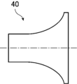
- each connecting member 40 may be a shape in which the peripheral wall is convexly curved toward the central axis of the connecting member 40, as shown in FIG. 6A.
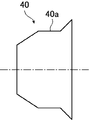
- each connecting member 40 may include a same-diameter portion 40a having a constant diameter size at an intermediate portion in the central axis direction (X direction) of the connecting member 40. good.
- the outer shape of each connection member 40 is not limited to a cylindrical shape, and may be a rectangular tube shape.
- the connecting member 40 is connected to both the inlet opening 16A and the outlet opening 18A, but the present invention is not limited to this, and the connecting member is connected to only one of the inlet opening 16A and the outlet opening 18A. 40 may be connected. Also, the connection member 40 may not be provided at either the inlet opening 16A or the outlet opening 18A.
- the ventilation path muffler 10 muffles the sound in the ventilation path through vibration by the vibrating section 20 , acoustic resonance inside the housing 12 , resonance in the back space of the connecting member 40 , and sound absorption by the sound absorbing member 30 .
- ⁇ /4 resonance is, for example, the resonance in the Z direction in FIG.
- FIG. 7 shows calculation results by the finite element method for the acoustic intensity vector at ⁇ /4 resonance and the sound energy distribution within the housing 12 .
- the sound energy can be effectively propagated in the direction in which the sound energy spreads inside the housing 12 instead of the flow path (ventilation path). .
- the inlet opening 16 and the outlet opening 18 are located at a position biased toward the end side of the housing 12 in the longitudinal direction (Z direction) of the housing 12, and the apex of the inner wall surface of the housing 12 further away from the face.
- the vibrating portion 20 vibrates at the first natural frequency f1 that satisfies the above-described formula (1).
- sound on the lower frequency side than the frequency of the sound whose ⁇ /4 corresponds to the distance L is emitted to the outside of the housing 12 by resonance.
- low frequency sounds can be silenced.
- 8 and 10 to 15 show graphs showing the silencing characteristics of the muffler for air passages, where the horizontal axis represents frequency (unit: Hz) and the vertical axis represents transmission loss (unit: dB). .
- FIG. 8 shows a graph for "no sound absorbing material and no vibration", a graph for "no sound absorbing material and with vibration", and a graph for "with sound absorbing material and vibration". is shown.
- the back space of the connection member 40 acts as a kind of resonator, and the sound resonates in the back space H.
- the back space H is a space formed between the back surface of the inner wall surface of the housing 12 and the connecting member 40, which is closer to the connecting member 40, and shrinks closer to the center position of the housing 12 in the X direction. (See Figure 1).
- the back space H (specifically, the back space H of the connecting member 42 on the upstream side) resonates on a principle similar to that of a Helmholtz resonator, as shown in FIG. Due to the resonance in the back space H, the sound of the resonance frequency can be silenced.
- the frequency band to be silenced can be reduced in frequency. There is a need to.
- the muffled sound due to the vibration of the vibrating portion 20 can be used to reduce the frequency band to be muffled without changing the distance L.
- the ventilation path silencer 10 of the present embodiment even if the size of the housing 12 is relatively compact, it is possible to muffle a wide range of sounds from low-frequency sounds to high-frequency sounds. can.
- broad noise reduction can be obtained by using both the noise reduction by the housing 12 and the noise reduction member by the sound absorbing member 30. .
- the internal structure of the muffler for air passage of the present invention is not limited to the example shown in FIG. 1, and an example shown in FIG.
- the sound absorbing member 30 is arranged in a region of the internal space of the housing 12 on the side where the connection member 40 is provided in the Z direction. More specifically, the panel-shaped sound absorbing member 30 is arranged along the end surface of the inner wall surface of the housing 12 on the side where the connection member 40 is provided in the Z direction.
- the connecting members 40 on the upstream and downstream sides are arranged adjacent to the sound absorbing material 30 in the Z direction.
- the existence range of the entrance opening 16A and the existence range of the exit opening 18A in the Y direction and the Z direction overlap.
- a rear space 60 is provided in the internal space of the housing 12 on the side opposite to the sound absorbing member 30 in the Z direction.
- a partition member 62 for partitioning the back space 60 is arranged in the back space 60 .
- the partition member 62 is a flat plate-like member and partitions the rear space 60 into two spaces in the Z direction. Of the two spaces, the first space 60a that is farther away from the sound absorbing member 30 has a shorter length in the Z direction and a smaller volume than the second space 60b that is closer to the sound absorbing member 30 .
- the partition member 62 extends straight along the X direction from the upstream end surface of the inner wall surface of the housing 12 , and its tip is separated from the downstream end surface of the inner wall surface of the housing 12 .
- a relatively wide gap is formed between the tip 62 of the partition member and the inner wall surface of the housing 12 (more specifically, the end surface on the downstream side). This gap corresponds to a communicating portion 60c that communicates the first space 60a and the second space 60b.
- the first space 60a having the smaller volume constitutes a resonance space that absorbs sound by resonance.
- the first space 60a functions as an air column resonator by generating a standing wave in the space having the communicating portion 60c (gap).
- the air column resonator can absorb the sound of that frequency by adjusting its resonance frequency to the frequency of the sound to be silenced.
- the portion of the housing 12 adjacent to the rear space 60 in the X and Y directions constitutes a vibrating portion. More specifically, of the portion forming the maximum outer wall surface of the wall 14 of the housing 12, the portion adjacent to the first space 60a constitutes the first vibrating portion 24, and the portion adjacent to the second space 60b constitutes the second vibrating portion 24. A vibrating portion 26 is formed. Note that in FIG. 19B and FIG. 20B described later, the devices inside the housing 12 are illustrated with dashed lines in order to show the positional relationship between each vibrating unit and the devices inside the housing 12 .
- the existence range of the entrance opening 16A and the existence range of the exit opening 18A in the Y direction and the Z direction overlap, but the present invention is not limited to this. That is, as shown in FIG. 20A, the existence range of the entrance opening 16A and the existence range of the exit opening 18A may not overlap in the Y direction or the Z direction and may be separated from each other.
- the existence range of the entrance opening 16A and the existence range of the exit opening 18A are separated in the Z direction.
- the rear space 60 located on the opposite side of the sound absorbing member 30 in the Z direction is partitioned into two spaces aligned in the X direction by a partition member 62 extending in the Z direction, for example. It is The partition member 62 extends straight toward the sound absorbing member 30 from the end of the inner wall surface of the housing 12 opposite to the sound absorbing member 30 in the Z direction, and its tip is separated from the sound absorbing member 30 .
- the first space 60a positioned further upstream has a shorter length in the X direction and a smaller volume than the second space 60b positioned further downstream.
- a communicating portion 60c is formed as a relatively wide gap.
- the first space 60a having the smaller volume constitutes a resonance space that absorbs sound by resonance. That is, the first space 60a functions as an air column resonator by generating a standing wave in the space having the communicating portion 60c (gap).
- Example 1 A 3D printer was used to create a housing made of ABS (Acrylonitrile Butadiene Styrene) resin.
- the housing has a rectangular parallelepiped shape and has walls with a thickness of 2 mm.
- the ratio of the length of the longest side to the length of the shortest side was set to 2.6:1 in the outline of the cross section of the housing with the X direction as the normal direction.
- the housing had an inlet opening and an outlet opening, and each opening was connected to an air passage made of a hose with an inner diameter of 28 mm.
- the inlet and outlet openings were located 28 mm apart from the center position of the housing in the Z direction.
- QonPET manufactured by Bridgestone KBG Co., Ltd.
- QonPET which is a sound absorbing member
- the flow resistivity of this sound absorbing member is about 8000 Rayls/m.
- one surface of the housing specifically, the plate-shaped portion forming the maximum outer wall surface (130 mm x 110 mm surface) is configured to be able to vibrate as a vibrating section.
- the natural vibration calculation was performed using COMSOL Multiphysics. In the calculation, it was assumed that the periphery of the plate-like portion, which is the vibrating portion, was fixed and restrained. As a result of the analysis, it was found that the first natural frequency f1 (resonant frequency) of the vibrating portion was 358 Hz.
- Comparative example 1 In Comparative Example 1, the thickness of the wall of the housing was set to 20 mm to suppress vibration in the housing. Other than that, the configuration of Comparative Example 1 was the same as that of Example 1. Of the housing of Comparative Example 1, the plate-like portion forming the maximum outer wall surface (130 mm x 110 mm surface) was subjected to the above-described natural vibration analysis, and the first natural frequency f1 was 2799 Hz. rice field.
- a sound source was placed upstream of each of the airway silencers prepared in Example 1 and Comparative Example 1, sound was incident from the sound source, and the transmittance and reflectance of the incident sound in the airway silencers were measured. .
- the measurement was performed according to a known acoustic tube measurement method (specifically, ASTM E2611) by a microphone four-probe method using an acoustic tube with a diameter of 28 mm.
- (1-transmittance-reflectance) is defined as absorptance
- the sound absorption is obtained as an index indicating the amount of silencing in the muffler for air passage.
- a value of 10 ⁇ log 10 (1/transmittance) was obtained as a transmission loss.
- FIG. 10 shows the measurement results of transmission loss.
- Example 1 As can be seen from FIG. 10, a transmission loss peak appeared in the low frequency band, and specifically, a high transmission loss was shown with a peak at 355 Hz.
- Comparative Example 1 As can be seen from FIG. 10, no sharp peak appeared in the low frequency band regarding the transmission loss measurement results. This is because the first natural frequency f1 of the plate-shaped portion forming the maximum outer wall surface of the housing is 2799 Hz, which is higher than the specific resonance frequency fr and is not on the low frequency side.
- Example 2 In Example 2, the width of the housing (the length in the Z direction) was set to 90 mm. That is, the ratio of the length of the longest side to the length of the shortest side was set to 1.8:1 in the cross section of the housing of Example 2 with the X direction as the normal direction. Also, the positions of the inlet opening and the outlet opening in the housing were shifted from the central position of the housing by 18 mm in the Z direction. Except for this point, the configuration of the second embodiment is the same as that of the first embodiment.
- the precondition was that the periphery of the plate-like portion, which is the vibrating part, was fixed and constrained.
- Comparative example 2 In Comparative Example 2, the thickness of the wall of the housing was set to 20 mm to suppress vibration in the housing. Other than that, the configuration of Comparative Example 2 was the same as that of Example 2. Of the housing of Comparative Example 2, the plate-like portion forming the maximum outer wall surface (surface of 90 mm ⁇ 110 mm) was subjected to natural vibration analysis, and the first natural frequency f1 was 3760 Hz.
- Example 2 and Comparative Example 2 the transmittance and reflectance of the incident sound in the ventilation path silencer were measured in the same manner as in Example 1 and Comparative Example 1, and the transmission loss was measured.
- FIG. 11 shows the measurement results of the transmission loss.
- the peak of the transmission loss in the low frequency band in the muffler for ventilation path of Example 2 originates from the natural vibration of the vibrating portion of the housing.
- the transmission loss peak derived from the natural vibration of the vibrating portion occurs below fr/2 (that is, below 780 Hz).
- Example 3 similarly to Example 2, a transmission loss peak appeared near 500 Hz. Further, when comparing Example 2 and Example 3, in the low frequency band of 900 to 1800, Example 2 has a larger transmission loss, and in the band of 1900 Hz or higher, Example 3 has a larger transmission loss. became larger. This reflects the difference in the positions of the inlet and outlet openings in the housing. It was found that the silencing effect in the frequency band was improved.
- Example 2 the position where the inlet opening is provided (that is, the position where the hose is connected) is deviated from the central position of the housing. The distance between them is longer at 49mm.
- the resonance frequency in the ⁇ /4 resonance in Example 2 was a frequency corresponding to the above distance, specifically 1750 Hz.
- the muffling performance was enhanced around 1700 Hz, which is consistent with the fact that the transmission loss of the muffler of Example 3 exceeded that of the muffler of Example 3 in the low frequency band.
- Example 4 In Example 4, the width of the housing (the length in the Z direction) was set to 60 mm. In other words, the ratio of the length of the longest side to the length of the shortest side was set to 1.2:1 in the cross section of the housing of Example 4 with the X direction as the normal direction. In addition, the position where the inlet opening and the outlet opening are provided in the housing is the center position of the housing in the Z direction. Except for this point, the configuration of the fourth embodiment is the same as that of the first embodiment.
- the precondition was that the periphery of the plate-like portion, which is the vibrating part, was fixed and constrained.
- Comparative Example 3 In Comparative Example 3, the thickness of the wall of the housing was set to 20 mm to suppress vibration in the housing. Other than that, the configuration of Comparative Example 3 was the same as that of Example 4. Of the casing of Comparative Example 3, the above-described natural vibration analysis was performed on the plate-shaped portion forming the maximum outer wall surface (surface of 60 mm x 110 mm), and the first natural frequency f1 was 5834 Hz. rice field.
- Example 4 and Comparative Example 3 the transmittance and reflectance of the incident sound in the air passage muffler were measured in the same manner as in Example 1 and Comparative Example 1, and the transmission loss was measured.
- FIG. 13 shows the measurement results of the transmission loss.
- Example 4 the specific resonance frequency fr is 1559 Hz, and the first natural frequency f1 of the vibrating portion is smaller than fr and larger than fr/2. In other words, in Example 4, the transmission loss peak due to the natural vibration of the vibrating portion occurs in the range of fr/2 or more.
- Example 5 In Example 5, the connection member was fixed to each of the inlet opening and the outlet opening on the inner wall surface of the housing.
- the connecting member used in Example 5 has a length of 30 mm in the X direction and is fixed at its proximal end to the edge of each opening.
- the opening of the connection member (connection member side opening) widens toward the tip of the connection member, and the maximum opening width is 40 mm. Except for this point, the configuration of the fifth embodiment is the same as that of the second embodiment.
- Example 5 in the same manner as in Example 1, the transmittance and reflectance of the incident sound in the ventilation path silencer were measured, and the transmission loss was measured.
- FIG. 14 shows the measurement results of the transmission loss. 14 also shows the measurement results of Example 2 for comparison.
- Example 5 a transmission loss peak appeared at 530 Hz as in Example 2.
- the silencing effect on the low frequency side did not change depending on the presence or absence of the connection member.
- the resonance frequency of ⁇ /4 resonance which is determined by the distance to the top surface within the housing, is shifted to the low frequency side by providing the connection member within the housing. This is because the provision of the connection member formed a rear space with a narrow entrance between the connection member and the rear surface of the inner wall surface of the housing.
- the effect of Helmholtz resonance due to the back space is added to the ⁇ / 4 resonance in the housing, so that the resonance frequency of ⁇ / 4 resonance is lower than the resonance frequency when ⁇ / 4 resonance is perfect air column resonance. also shifted to the low frequency side.
- Example 6 and 7 a weight made of ABS resin was attached to the central portion of the maximum outer wall surface (that is, the vibrating portion) of the housing, and other points were the same as in Example 2.
- the radius of the weight was 20 mm and the height of the weight was 10 mm.
- the radius of the weight was 20 mm and the height of the weight was 20 mm.
- the housing and the weight were collectively formed by a 3D printer.
- FIG. 15 shows the measurement results of the transmission loss.
- FIG. 15 also shows the measurement results of Example 2 for comparison.
- the natural frequency was lowered by attaching the weight to the vibrating portion, and a transmission loss peak appeared on the lower frequency side.
- Example 8 a muffler 10 having a structure different from that of the above examples was produced by a 3D printer.
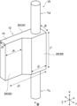
- the muffler 10 of Example 8 has a structure in which both ends of the wall 14 of the housing 12 have different shapes in the Y direction. Specifically, one end is made of an ABS plate with a thickness of 2 mm and has a rectangular surface of j1 ⁇ j3 as shown in FIG. The other end portion is made of an ABS plate with a thickness of 2 mm like the first vibrating portion 24, but has a bent portion in the middle in the Z direction.
- a second vibrating portion 26 and a third vibrating portion 28 two vibrating portions smaller than the first vibrating portion 24 (hereinafter referred to as a second vibrating portion 26 and a third vibrating portion 28) are provided at the other end portion with the bent portion interposed therebetween.
- the second vibrating portion 26 has a j1 ⁇ j2 rectangular surface as shown in FIG. 16, and the third vibrating portion 28 has a j1 ⁇ j4 rectangular surface.
- the first natural frequencies of the first vibrating portion 24, the second vibrating portion 26 and the third vibrating portion 28 were 286 Hz, 1078 Hz and 1283 Hz, respectively.
- QonPET which is a sound absorbing member, is arranged in all spaces other than the space connecting the inlet opening and the outlet opening (that is, the flow path).
- Example 9 the thickness of the first vibrating portion 24 was 2 mm, and the thickness of each of the second vibrating portion 26, the third vibrating portion 28, and the bent portion disposed therebetween was 20 mm.
- the second and third vibrating sections 26 and 28 are made stiffer than in the eighth embodiment for the purpose of verifying the effect of the vibration of the vibrating section, so that they are less likely to shake.
- the first natural frequency of the second vibrating portion 26 was 6264 Hz
- the first natural frequency of the third vibrating portion 28 was 7046 Hz.
- the configuration of the ninth embodiment is the same as that of the eighth embodiment.
- FIG. 17 shows the measurement results of the transmission loss.
- a relatively broad transmission loss peak was obtained in the vicinity of the first natural frequency band of 1078 to 1283 Hz of the second vibrating portion 26 and the third vibrating portion 28 .
- the transmission loss exceeded the transmission loss in the eighth embodiment.
- the first natural frequency of each vibrating part can be obtained for a plurality of frequencies. can express a transmission loss peak based on
- the path of the ventilation path (specifically, the flow path in the housing) changes by arranging the sound absorbing member inside the housing, resulting in wind noise. also change.
- the relationship between the installation amount of the sound absorbing member and the wind noise was determined by fluid calculation. Specifically, fluid calculation was performed using the CFD (Computer Fluid Dynamics) module of COMSOL, and the sound pressure of wind noise generated in the muffler was obtained using the Proudman Analogy method.
- the muffler to be calculated had the same structure as that of the second embodiment.
- the wind noise changes, and when the sound absorbing member accounts for 80% of the volume of the space inside the housing other than the flow path, , the wind noise is smaller than when no sound absorbing member is arranged. In this case, the sound absorbing member occupies 55% of the entire internal space of the housing. Further, as shown in FIG. 18, it was found that wind noise can be reduced by arranging more sound absorbing members in a space other than the ventilation portion to increase the occupancy of the sound absorbing members.
Landscapes
- Engineering & Computer Science (AREA)
- General Engineering & Computer Science (AREA)
- Chemical & Material Sciences (AREA)
- Combustion & Propulsion (AREA)
- Mechanical Engineering (AREA)
- Physics & Mathematics (AREA)
- Acoustics & Sound (AREA)
- Multimedia (AREA)
- Fluid Mechanics (AREA)
- Aviation & Aerospace Engineering (AREA)
- Duct Arrangements (AREA)
- Pipe Accessories (AREA)
- Soundproofing, Sound Blocking, And Sound Damping (AREA)
Priority Applications (5)
| Application Number | Priority Date | Filing Date | Title |
|---|---|---|---|
| JP2022575784A JPWO2023032618A1 (https=) | 2021-08-30 | 2022-08-09 | |
| CN202280057425.9A CN117859172A (zh) | 2021-08-30 | 2022-08-09 | 通气路用消声器 |
| EP22862384.9A EP4398238A4 (en) | 2021-08-30 | 2022-08-09 | Ventilation path silencer |
| JP2023151501A JP2023179506A (ja) | 2021-08-30 | 2023-09-19 | 通気路用消音器 |
| US18/442,971 US20240183576A1 (en) | 2021-08-30 | 2024-02-15 | Silencer for ventilation passage |
Applications Claiming Priority (4)
| Application Number | Priority Date | Filing Date | Title |
|---|---|---|---|
| JP2021139628 | 2021-08-30 | ||
| JP2021-139628 | 2021-08-30 | ||
| JP2022118691 | 2022-07-26 | ||
| JP2022-118691 | 2022-07-26 |
Related Child Applications (1)
| Application Number | Title | Priority Date | Filing Date |
|---|---|---|---|
| US18/442,971 Continuation US20240183576A1 (en) | 2021-08-30 | 2024-02-15 | Silencer for ventilation passage |
Publications (1)
| Publication Number | Publication Date |
|---|---|
| WO2023032618A1 true WO2023032618A1 (ja) | 2023-03-09 |
Family
ID=85412248
Family Applications (1)
| Application Number | Title | Priority Date | Filing Date |
|---|---|---|---|
| PCT/JP2022/030476 Ceased WO2023032618A1 (ja) | 2021-08-30 | 2022-08-09 | 通気路用消音器 |
Country Status (4)
| Country | Link |
|---|---|
| US (1) | US20240183576A1 (https=) |
| EP (1) | EP4398238A4 (https=) |
| JP (2) | JPWO2023032618A1 (https=) |
| WO (1) | WO2023032618A1 (https=) |
Cited By (1)
| Publication number | Priority date | Publication date | Assignee | Title |
|---|---|---|---|---|
| JP7629121B1 (ja) | 2024-01-19 | 2025-02-12 | 富士フイルム株式会社 | 消音器 |
Families Citing this family (1)
| Publication number | Priority date | Publication date | Assignee | Title |
|---|---|---|---|---|
| WO2026014087A1 (ja) * | 2024-07-10 | 2026-01-15 | 富士フイルム株式会社 | 送風機 |
Citations (5)
| Publication number | Priority date | Publication date | Assignee | Title |
|---|---|---|---|---|
| JP2009198902A (ja) * | 2008-02-22 | 2009-09-03 | Yamaha Corp | 吸音構造、吸音構造群、音響室、吸音構造の調整方法及び騒音低減方法 |
| JP2010111347A (ja) * | 2008-11-10 | 2010-05-20 | Yamaha Corp | 吸音構造体及び音響室 |
| JP2010116118A (ja) * | 2008-11-14 | 2010-05-27 | Yamaha Corp | ダクト及び車両構造体 |
| JP2016133226A (ja) | 2015-01-15 | 2016-07-25 | 三菱電機株式会社 | 送風機の消音器 |
| WO2019074061A1 (ja) * | 2017-10-11 | 2019-04-18 | 富士フイルム株式会社 | 箱型防音構造体および輸送機器 |
Family Cites Families (7)
| Publication number | Priority date | Publication date | Assignee | Title |
|---|---|---|---|---|
| JPS5843609Y2 (ja) * | 1978-08-23 | 1983-10-03 | カルソニックカンセイ株式会社 | 消音器 |
| JPS5615487Y2 (https=) * | 1978-08-25 | 1981-04-10 | ||
| JP2741181B2 (ja) * | 1995-06-12 | 1998-04-15 | 藤壷技研工業株式会社 | 自動車用消音器 |
| US6988057B2 (en) * | 2003-10-31 | 2006-01-17 | The Hong Kong Polytechnic University | Methods for designing a chamber to reduce noise in a duct |
| JP5540481B2 (ja) * | 2008-08-28 | 2014-07-02 | ヤマハ株式会社 | 板振動吸音装置および板振動吸音方法 |
| WO2020080112A1 (ja) * | 2018-10-19 | 2020-04-23 | 富士フイルム株式会社 | 音響システム |
| EP3961046B1 (en) * | 2019-04-24 | 2025-10-01 | FUJIFILM Corporation | Fan muffling system |
-
2022
- 2022-08-09 EP EP22862384.9A patent/EP4398238A4/en not_active Withdrawn
- 2022-08-09 WO PCT/JP2022/030476 patent/WO2023032618A1/ja not_active Ceased
- 2022-08-09 JP JP2022575784A patent/JPWO2023032618A1/ja active Pending
-
2023
- 2023-09-19 JP JP2023151501A patent/JP2023179506A/ja active Pending
-
2024
- 2024-02-15 US US18/442,971 patent/US20240183576A1/en active Pending
Patent Citations (5)
| Publication number | Priority date | Publication date | Assignee | Title |
|---|---|---|---|---|
| JP2009198902A (ja) * | 2008-02-22 | 2009-09-03 | Yamaha Corp | 吸音構造、吸音構造群、音響室、吸音構造の調整方法及び騒音低減方法 |
| JP2010111347A (ja) * | 2008-11-10 | 2010-05-20 | Yamaha Corp | 吸音構造体及び音響室 |
| JP2010116118A (ja) * | 2008-11-14 | 2010-05-27 | Yamaha Corp | ダクト及び車両構造体 |
| JP2016133226A (ja) | 2015-01-15 | 2016-07-25 | 三菱電機株式会社 | 送風機の消音器 |
| WO2019074061A1 (ja) * | 2017-10-11 | 2019-04-18 | 富士フイルム株式会社 | 箱型防音構造体および輸送機器 |
Cited By (2)
| Publication number | Priority date | Publication date | Assignee | Title |
|---|---|---|---|---|
| JP7629121B1 (ja) | 2024-01-19 | 2025-02-12 | 富士フイルム株式会社 | 消音器 |
| JP2025112489A (ja) * | 2024-01-19 | 2025-08-01 | 富士フイルム株式会社 | 消音器 |
Also Published As
| Publication number | Publication date |
|---|---|
| JPWO2023032618A1 (https=) | 2023-03-09 |
| US20240183576A1 (en) | 2024-06-06 |
| EP4398238A4 (en) | 2025-01-01 |
| EP4398238A1 (en) | 2024-07-10 |
| JP2023179506A (ja) | 2023-12-19 |
Similar Documents
| Publication | Publication Date | Title |
|---|---|---|
| US11841163B2 (en) | Silencing system | |
| JP6672391B2 (ja) | 消音システム | |
| JP2023098879A (ja) | ファン消音システム | |
| JP6847246B2 (ja) | 防音構造体 | |
| WO2020080040A1 (ja) | 防音システム | |
| US20240183576A1 (en) | Silencer for ventilation passage | |
| JP2019056516A (ja) | 消音システム | |
| JP2020024354A (ja) | 防音システム | |
| JP6672390B2 (ja) | 消音システム | |
| JP7627350B2 (ja) | 通風型消音器 | |
| JP7792398B2 (ja) | 音響インピーダンス変化構造および通風型消音器 | |
| US12529487B2 (en) | Ventilation path with soundproof structure | |
| US20240426514A1 (en) | Ventilation-type silencer | |
| JP7702494B2 (ja) | 通気システム | |
| CN117859172A (zh) | 通气路用消声器 | |
| CN118140085A (zh) | 通气系统 | |
| JP7629121B1 (ja) | 消音器 | |
| JP2008061674A (ja) | 電気掃除機 | |
| US20250225967A1 (en) | Silencing structure | |
| CN117859171A (zh) | 通风型消音器 | |
| JP2025112511A (ja) | 消音器付き風路 |
Legal Events
| Date | Code | Title | Description |
|---|---|---|---|
| ENP | Entry into the national phase |
Ref document number: 2022575784 Country of ref document: JP Kind code of ref document: A |
|
| 121 | Ep: the epo has been informed by wipo that ep was designated in this application |
Ref document number: 22862384 Country of ref document: EP Kind code of ref document: A1 |
|
| WWE | Wipo information: entry into national phase |
Ref document number: 202280057425.9 Country of ref document: CN |
|
| WWE | Wipo information: entry into national phase |
Ref document number: 2022862384 Country of ref document: EP |
|
| NENP | Non-entry into the national phase |
Ref country code: DE |
|
| ENP | Entry into the national phase |
Ref document number: 2022862384 Country of ref document: EP Effective date: 20240402 |
|
| WWW | Wipo information: withdrawn in national office |
Ref document number: 2022862384 Country of ref document: EP |