WO2023031721A1 - 二次電池管理システム - Google Patents
二次電池管理システム Download PDFInfo
- Publication number
- WO2023031721A1 WO2023031721A1 PCT/IB2022/057828 IB2022057828W WO2023031721A1 WO 2023031721 A1 WO2023031721 A1 WO 2023031721A1 IB 2022057828 W IB2022057828 W IB 2022057828W WO 2023031721 A1 WO2023031721 A1 WO 2023031721A1
- Authority
- WO
- WIPO (PCT)
- Prior art keywords
- secondary battery
- circuit
- charging
- voltage
- management system
- Prior art date
- Legal status (The legal status is an assumption and is not a legal conclusion. Google has not performed a legal analysis and makes no representation as to the accuracy of the status listed.)
- Ceased
Links
Images

















Classifications
-
- H—ELECTRICITY
- H02—GENERATION; CONVERSION OR DISTRIBUTION OF ELECTRIC POWER
- H02J—ELECTRIC POWER NETWORKS; CIRCUIT ARRANGEMENTS OR SYSTEMS FOR SUPPLYING OR DISTRIBUTING ELECTRIC POWER; SYSTEMS FOR STORING ELECTRIC ENERGY
- H02J7/00—Circuit arrangements for charging or discharging batteries or for supplying loads from batteries
- H02J7/90—Regulation of charging or discharging current or voltage
- H02J7/96—Regulation of charging or discharging current or voltage in response to battery voltage
-
- C—CHEMISTRY; METALLURGY
- C01—INORGANIC CHEMISTRY
- C01G—COMPOUNDS CONTAINING METALS NOT COVERED BY SUBCLASSES C01D OR C01F
- C01G51/00—Compounds of cobalt
- C01G51/40—Complex oxides containing cobalt and at least one other metal element
- C01G51/42—Complex oxides containing cobalt and at least one other metal element containing alkali metals, e.g. LiCoO2
-
- H—ELECTRICITY
- H01—ELECTRIC ELEMENTS
- H01M—PROCESSES OR MEANS, e.g. BATTERIES, FOR THE DIRECT CONVERSION OF CHEMICAL ENERGY INTO ELECTRICAL ENERGY
- H01M10/00—Secondary cells; Manufacture thereof
- H01M10/42—Methods or arrangements for servicing or maintenance of secondary cells or secondary half-cells
- H01M10/425—Structural combination with electronic components, e.g. electronic circuits integrated to the outside of the casing
-
- H—ELECTRICITY
- H01—ELECTRIC ELEMENTS
- H01M—PROCESSES OR MEANS, e.g. BATTERIES, FOR THE DIRECT CONVERSION OF CHEMICAL ENERGY INTO ELECTRICAL ENERGY
- H01M10/00—Secondary cells; Manufacture thereof
- H01M10/42—Methods or arrangements for servicing or maintenance of secondary cells or secondary half-cells
- H01M10/44—Methods for charging or discharging
-
- H—ELECTRICITY
- H01—ELECTRIC ELEMENTS
- H01M—PROCESSES OR MEANS, e.g. BATTERIES, FOR THE DIRECT CONVERSION OF CHEMICAL ENERGY INTO ELECTRICAL ENERGY
- H01M10/00—Secondary cells; Manufacture thereof
- H01M10/42—Methods or arrangements for servicing or maintenance of secondary cells or secondary half-cells
- H01M10/48—Accumulators combined with arrangements for measuring, testing or indicating the condition of cells, e.g. the level or density of the electrolyte
-
- H—ELECTRICITY
- H01—ELECTRIC ELEMENTS
- H01M—PROCESSES OR MEANS, e.g. BATTERIES, FOR THE DIRECT CONVERSION OF CHEMICAL ENERGY INTO ELECTRICAL ENERGY
- H01M4/00—Electrodes
- H01M4/02—Electrodes composed of, or comprising, active material
- H01M4/36—Selection of substances as active materials, active masses, active liquids
- H01M4/362—Composites
- H01M4/366—Composites as layered products
-
- H—ELECTRICITY
- H01—ELECTRIC ELEMENTS
- H01M—PROCESSES OR MEANS, e.g. BATTERIES, FOR THE DIRECT CONVERSION OF CHEMICAL ENERGY INTO ELECTRICAL ENERGY
- H01M4/00—Electrodes
- H01M4/02—Electrodes composed of, or comprising, active material
- H01M4/36—Selection of substances as active materials, active masses, active liquids
- H01M4/38—Selection of substances as active materials, active masses, active liquids of elements or alloys
- H01M4/381—Alkaline or alkaline earth metals elements
- H01M4/382—Lithium
-
- H—ELECTRICITY
- H01—ELECTRIC ELEMENTS
- H01M—PROCESSES OR MEANS, e.g. BATTERIES, FOR THE DIRECT CONVERSION OF CHEMICAL ENERGY INTO ELECTRICAL ENERGY
- H01M4/00—Electrodes
- H01M4/02—Electrodes composed of, or comprising, active material
- H01M4/36—Selection of substances as active materials, active masses, active liquids
- H01M4/48—Selection of substances as active materials, active masses, active liquids of inorganic oxides or hydroxides
- H01M4/52—Selection of substances as active materials, active masses, active liquids of inorganic oxides or hydroxides of nickel, cobalt or iron
- H01M4/525—Selection of substances as active materials, active masses, active liquids of inorganic oxides or hydroxides of nickel, cobalt or iron of mixed oxides or hydroxides containing iron, cobalt or nickel for inserting or intercalating light metals, e.g. LiNiO2, LiCoO2 or LiCoOxFy
-
- H—ELECTRICITY
- H01—ELECTRIC ELEMENTS
- H01M—PROCESSES OR MEANS, e.g. BATTERIES, FOR THE DIRECT CONVERSION OF CHEMICAL ENERGY INTO ELECTRICAL ENERGY
- H01M4/00—Electrodes
- H01M4/02—Electrodes composed of, or comprising, active material
- H01M4/36—Selection of substances as active materials, active masses, active liquids
- H01M4/58—Selection of substances as active materials, active masses, active liquids of inorganic compounds other than oxides or hydroxides, e.g. sulfides, selenides, tellurides, halogenides or LiCoFy; of polyanionic structures, e.g. phosphates, silicates or borates
- H01M4/583—Carbonaceous material, e.g. graphite-intercalation compounds or CFx
-
- H—ELECTRICITY
- H02—GENERATION; CONVERSION OR DISTRIBUTION OF ELECTRIC POWER
- H02J—ELECTRIC POWER NETWORKS; CIRCUIT ARRANGEMENTS OR SYSTEMS FOR SUPPLYING OR DISTRIBUTING ELECTRIC POWER; SYSTEMS FOR STORING ELECTRIC ENERGY
- H02J7/00—Circuit arrangements for charging or discharging batteries or for supplying loads from batteries
- H02J7/90—Regulation of charging or discharging current or voltage
- H02J7/94—Regulation of charging or discharging current or voltage in response to battery current
-
- H—ELECTRICITY
- H02—GENERATION; CONVERSION OR DISTRIBUTION OF ELECTRIC POWER
- H02J—ELECTRIC POWER NETWORKS; CIRCUIT ARRANGEMENTS OR SYSTEMS FOR SUPPLYING OR DISTRIBUTING ELECTRIC POWER; SYSTEMS FOR STORING ELECTRIC ENERGY
- H02J7/00—Circuit arrangements for charging or discharging batteries or for supplying loads from batteries
- H02J7/90—Regulation of charging or discharging current or voltage
- H02J7/96—Regulation of charging or discharging current or voltage in response to battery voltage
- H02J7/963—Regulation of charging or discharging current or voltage in response to battery voltage in response to battery voltage gradient
-
- H—ELECTRICITY
- H01—ELECTRIC ELEMENTS
- H01M—PROCESSES OR MEANS, e.g. BATTERIES, FOR THE DIRECT CONVERSION OF CHEMICAL ENERGY INTO ELECTRICAL ENERGY
- H01M10/00—Secondary cells; Manufacture thereof
- H01M10/42—Methods or arrangements for servicing or maintenance of secondary cells or secondary half-cells
- H01M10/425—Structural combination with electronic components, e.g. electronic circuits integrated to the outside of the casing
- H01M2010/4271—Battery management systems including electronic circuits, e.g. control of current or voltage to keep battery in healthy state, cell balancing
-
- Y—GENERAL TAGGING OF NEW TECHNOLOGICAL DEVELOPMENTS; GENERAL TAGGING OF CROSS-SECTIONAL TECHNOLOGIES SPANNING OVER SEVERAL SECTIONS OF THE IPC; TECHNICAL SUBJECTS COVERED BY FORMER USPC CROSS-REFERENCE ART COLLECTIONS [XRACs] AND DIGESTS
- Y02—TECHNOLOGIES OR APPLICATIONS FOR MITIGATION OR ADAPTATION AGAINST CLIMATE CHANGE
- Y02E—REDUCTION OF GREENHOUSE GAS [GHG] EMISSIONS, RELATED TO ENERGY GENERATION, TRANSMISSION OR DISTRIBUTION
- Y02E60/00—Enabling technologies; Technologies with a potential or indirect contribution to GHG emissions mitigation
- Y02E60/10—Energy storage using batteries
Definitions
- One aspect of the present invention relates to a secondary battery management system.
- a technical field of one embodiment of the present invention disclosed in this specification and the like includes semiconductor devices, light-emitting devices, power storage devices, storage devices, electronic devices, lighting devices, input devices, or input/output devices. A method is also included.
- a secondary battery can be used repeatedly by being charged unlike a primary battery, and is also called a storage battery or a battery. Charging is sending electricity into a secondary battery, and discharging is taking electricity out of a secondary battery.
- a secondary battery using lithium ions as carrier ions is called a lithium ion secondary battery or a lithium ion battery.
- Lithium-ion secondary batteries can be made high-capacity and small-sized, and are installed in electronic devices and the like.
- the voltage during charging of the secondary battery has an upper limit determined in consideration of safety, and in this specification and the like, this is referred to as the upper limit voltage.
- the upper limit voltage is sometimes referred to as maximum charge voltage, final voltage, specified voltage, or full charge voltage.
- the upper limit voltage of a secondary battery using lithium cobaltate for the positive electrode and graphite for the negative electrode is about 4.2V. Since increasing the upper limit voltage increases the capacity of the secondary battery, research and development are being conducted on methods for increasing the upper limit voltage.
- Patent Document 1 describes the charging power limit.
- the charging power limit of Patent Document 1 is determined from the predicted terminal voltage and total resistance by predicting the terminal voltage and total resistance of the secondary battery using an equivalent circuit model of the secondary battery.
- Patent Document 1 also describes that the temperature measured by the temperature measurement unit is transmitted to the control unit, and the voltage source determines the open circuit voltage (V OCV ) from the state of charge (SOC) and temperature of the secondary battery. .
- Patent Document 1 the crystal structure of an active material, such as a positive electrode active material, is not taken into consideration in determining the charge power limit. Therefore, in some cases, the prediction using the simple equivalent circuit model of Patent Document 1 cannot raise the charging power limit so much.
- Patent Document 1 does not recognize a low temperature such as -40°C at all. Battery characteristics at such low temperatures are significantly different from battery characteristics at so-called room temperature of about 25° C., and the discharge capacity is lower at lower temperatures than at room temperature. That is, increasing the upper limit voltage is particularly desired at low temperatures.
- an object of one embodiment of the present invention is to provide a secondary battery management system in which the upper limit voltage is increased to the limit and charging/discharging is possible even at low temperatures.
- one aspect of the present invention provides a secondary battery management system that raises the upper limit voltage to the limit by deriving an optimum voltage that takes into account the crystal structure of the positive electrode active material, and is capable of charging and discharging even at low temperatures. do.
- low temperature is ⁇ 50° C. or higher and 0° C. or lower
- room temperature is higher than 0° C. and 35° C. or lower
- high temperature is higher than 35° C. and 65° C. or lower.
- Temperatures lower than 0°C are sometimes referred to as below freezing.
- One embodiment of the present invention includes a secondary battery that is charged and discharged at ⁇ 50° C. to 0° C., a first circuit having a function of measuring the voltage of the secondary battery, and a function of measuring the current of the secondary battery. and a control circuit to which voltage information from the first circuit or current information from the second circuit is input, the control circuit charging the secondary battery
- the control circuit calculates data indicating battery characteristics based on the values input from the first circuit or the second circuit, the control circuit detects a maximum value for the data, and the control circuit detects the maximum value It is a secondary battery management system that stops charging when a value is detected.
- One embodiment of the present invention includes a secondary battery that is charged and discharged at ⁇ 50° C. to 0° C., a first circuit having a function of measuring the voltage of the secondary battery, and a function of measuring the current of the secondary battery.
- a control circuit to which voltage information from the first circuit or current information from the second circuit is input; and a temperature sensor electrically connected to the control circuit.
- the control circuit measures the temperature of the secondary battery using the temperature sensor, the control circuit starts charging the secondary battery, and the control circuit receives input from the first circuit or the second circuit. Based on the obtained value, data indicating battery characteristics corresponding to temperature is calculated, the control circuit detects the maximum value for the data, and the control circuit stops charging when the maximum value is detected.
- Secondary battery management system to which voltage information from the first circuit or current information from the second circuit is input.
- One embodiment of the present invention includes a secondary battery that is charged and discharged at ⁇ 50° C. to 0° C., a first circuit having a function of measuring the voltage of the secondary battery, and a function of measuring the current of the secondary battery. and a control circuit to which voltage information from the first circuit or current information from the second circuit is input, the control circuit storing the temperature of the secondary battery dt/ It is a secondary battery management system that calculates the value of dV, the control circuit detects the maximum value in dt/dV, and the control circuit stops charging when the maximum value is detected.
- control circuit performs an averaging process on dt/dV, and the difference value between the second value and the first value of dt/dV in the comparison range is the first value. It is preferable to be able to
- charging is preferably performed at a constant current.
- the secondary battery has a positive electrode, the positive electrode contains lithium cobalt oxide, and the crystal structure identified by X-ray diffraction is a crystal structure represented by the space group R-3m. and preferred.
- lithium cobaltate preferably has magnesium in the surface layer.
- the secondary battery has a negative electrode, and the negative electrode preferably contains lithium metal or graphite.
- a secondary battery management system capable of raising the upper limit voltage to the limit.
- a secondary battery management system capable of charging and discharging even at low temperatures can be provided.
- FIG. 1A to 1C are block diagrams showing an example of a secondary battery management system.
- 2A and 2B are block diagrams showing an example of a secondary battery management system.
- FIG. 3 is a flowchart for explaining the charging method of the secondary battery management system.
- FIG. 4 is a flowchart for explaining the charging method of the secondary battery management system.
- FIG. 5 is a block diagram showing an example of a secondary battery management system.
- FIG. 6 is a block diagram showing an example of a secondary battery management system.
- 7A and 7B are block diagrams showing an example of a secondary battery management system.
- FIG. 8 is a flowchart for explaining difference processing.
- FIG. 9 is a diagram for explaining the crystal structure of the positive electrode active material.
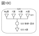
- FIGS. 10A to 10C are diagrams illustrating an example of a method for manufacturing a positive electrode active material.
- FIG. 11 is a diagram illustrating an example of a method for producing a positive electrode active material.
- FIG. 12 is a diagram illustrating an example of a method for producing a positive electrode active material.
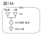
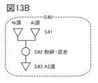
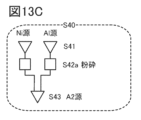
- 13A to 13C are diagrams illustrating an example of a method for manufacturing a positive electrode active material.
- FIG. 14 is a diagram illustrating an example of a laminated secondary battery.
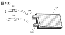
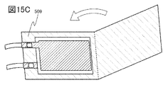
- 15A to 15C are diagrams illustrating an example of a method for manufacturing a laminated secondary battery.
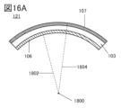
- 16A and 16B are diagrams illustrating an example of a bendable secondary battery.
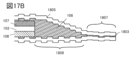
- 17A and 17B are diagrams illustrating a part of a secondary battery that bends.
- FIG. 11 is a diagram illustrating an example of a method for producing a positive electrode active material.
- FIG. 12 is a diagram illustrating an example of a method for producing a positive electrode active material.
- 18 is a block diagram showing an example of a vehicle having a motor.
- 19A to 19E are diagrams showing an example of a transportation vehicle.
- 20A and 20B are diagrams illustrating a house using secondary batteries.
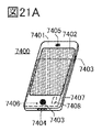
- 21A to 21E are diagrams illustrating examples of electronic devices.
- 22A to 22C are diagrams illustrating examples of electronic devices.
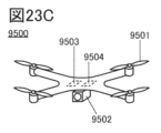
- 23A to 23D are diagrams illustrating an example of an electronic device or the like.
- FIG. 24 is a graph showing the results of Examples.
- FIG. 25 is a graph showing the results of Examples.
- top views also referred to as “plan views”
- perspective views and the like, description of some components may be omitted for clarity of the drawings.
- electrically connected includes a case of direct connection and a case of connection via "something having some electrical effect".
- something that has some kind of electrical action is not particularly limited as long as it enables transmission and reception of electrical signals between connection objects. Therefore, even if it is expressed as “electrically connected", there may be no physical connection part in the actual circuit.
- crystal planes and directions are indicated by Miller indices. Crystallographic planes and orientations are indicated by adding a superscript bar to the number from the standpoint of crystallography. symbol) may be attached.
- individual orientations that indicate directions within the crystal are [ ]
- collective orientations that indicate all equivalent directions are ⁇ >
- individual planes that indicate crystal planes are ( )
- collective planes that have equivalent symmetry are ⁇ ⁇ to express each.
- segregation refers to a phenomenon in which a certain element (eg, B) is spatially non-uniformly distributed in a solid composed of a plurality of elements (eg, A, B, and C).
- the surface layer portion of a particle such as an active material refers to a region within 10 nm, a region within 50 nm, or a region within 5 nm vertically or substantially vertically from the surface toward the inside.
- Subsurface is synonymous with near-surface, near-surface region or shell.
- vertical or substantially vertical specifically means a range of 80° or more and 100° or less from the surface.
- Surfaces caused by cracks or cracks may also be referred to as surfaces.
- a region deeper than the surface layer of the positive electrode active material is called a bulk. Bulk is synonymous with internal or core.
- the layered rock salt-type crystal structure of the composite oxide containing lithium and a transition metal means a rock salt-type crystal structure in which cations and anions are alternately arranged.
- Lithium can diffuse two-dimensionally because it has an ion arrangement and the transition metal and lithium form a regular arrangement to form a plane.
- the composite oxide may have defects such as lack of cations or anions.
- the layered rock salt type crystal structure may have a structure in which the lattice of the rock salt type crystal structure is distorted.
- a rock salt crystal structure refers to a structure in which cations and anions are alternately arranged.
- the rock salt type crystal structure may have cation or anion defects.
- the O3′ type crystal structure possessed by a composite oxide containing lithium and a transition metal belongs to the space group R-3m, and although it is not a spinel type crystal structure, ions such as cobalt and magnesium are oxygen It refers to a crystal structure that occupies six coordinated positions and has a symmetry similar to that of a spinel in the arrangement of cations.
- a light element such as lithium may occupy four oxygen-coordinated sites.
- the O3′-type crystal structure is similar to the CdCl 2 -type crystal structure, although it has Li randomly between the layers. It is known that known lithium cobaltate or layered rock salt-type positive electrode active materials containing a large amount of cobalt generally do not have a crystal structure similar to the CdCl 2 type.
- Anions in each of the layered rock salt crystal structure and the rock salt crystal structure have a cubic close-packed structure (face-centered cubic lattice structure).
- the layered rock salt type crystal structure and the rock salt type crystal structure are in contact with each other, there exists a crystal plane in which the direction of the cubic close-packed structure composed of anions is aligned.
- the space group of the layered rocksalt crystal structure is R-3m
- the space groups of the rocksalt crystal structure are Fm-3m (the space group of general rocksalt crystals) and Fd-3m (the simplest symmetry).
- the space group of rock salt type crystals having the same orientation is different from each other.
- the orientation of the cubic close-packed structure composed of anions when the orientation of the cubic close-packed structure composed of anions is aligned, the orientation of the crystals may be said to match or substantially match.
- anions are presumed to have a cubic close-packed structure, so the layered rocksalt-type crystal structure is replaced with the O3′-type crystal structure, and the crystal planes aligned with the rocksalt-type crystal structure. can understand.
- the space group of the crystal structure is identified by X-ray diffraction (XRD), electron beam diffraction, neutron beam diffraction, and the like.
- XRD and the like shall be measured at room temperature or above. Therefore, in this specification and the like, belonging to a certain space group, belonging to a certain space group, or being in a certain space group can be rephrased as being identified by a certain space group.
- a structure in which three layers of negative ions are stacked in a mutually displaced manner such as ABCABC
- ABCABC a structure in which three layers of negative ions are stacked in a mutually displaced manner
- anions do not have to form a strictly cubic lattice.
- the analysis results do not necessarily match the theory.
- FFT Fast Fourier Transform
- spots may appear at positions slightly different from their theoretical positions. For example, if the deviation between the theoretical position and orientation is 5 degrees or less, or 2.5 degrees or less, it can be said that a cubic close-packed structure is obtained.
- a secondary battery for example, has a positive electrode and a negative electrode.
- a positive electrode active material is one of the materials that constitute the positive electrode.
- the positive electrode active material is a material that undergoes a reaction that contributes to charge/discharge capacity, and is specifically a compound containing a transition metal capable of intercalating and deintercalating lithium and oxygen, or a composite oxide containing a transition metal.
- the positive electrode active material may be expressed as a composite oxide, a positive electrode material, a positive electrode material, a positive electrode material for a lithium ion battery, and the like.
- the secondary battery management system which is one embodiment of the present invention, can change the optimum charging/discharging conditions according to the operating temperature of the secondary battery.
- the temperature of the secondary battery includes the temperature inside the secondary battery and the temperature outside the secondary battery. Furthermore, the temperature outside the secondary battery includes the temperature of the secondary battery exterior body, the temperature of the housing in which the exterior body is enclosed, and the environmental temperature in which the secondary battery is placed. In this specification and the like, the ambient temperature is sometimes referred to as the operating temperature of the secondary battery. In the secondary battery management system, it is possible to distinguish the temperature according to the position of the temperature sensor as described above, but it is possible to provide the secondary battery management system by using any temperature.
- the temperature in the charge/discharge cycle test in this specification and the like refers to the temperature of the constant temperature bath in which the lithium ion secondary battery is placed. Allow sufficient time (e.g., 1 hour or more) until the temperature of the lithium-ion secondary battery to be measured (e.g., test battery) placed in the thermostatic chamber reaches the same level as the temperature of the thermostatic chamber before measurement. Good to start.
- the temperature of the constant temperature bath corresponds to the temperature of the secondary battery management system described above.
- the energy barrier tends to increase when lithium ions are desorbed from the positive electrode active material. That is, it can be said that the lower the temperature during charging, the higher the overvoltage required to detach lithium ions from the positive electrode active material, and the positive electrode active material may be exposed to a high voltage (high potential relative to the potential of lithium). be. In other words, in charging at low temperatures, the charge capacity may decrease unless the positive electrode active material is exposed to a high voltage. Therefore, the present inventors considered that it is preferable to use a positive electrode active material capable of withstanding high voltage as a positive electrode active material possessed by a lithium-ion battery having excellent charge and discharge characteristics even at low temperatures.
- the present inventors considered that it is important to maximize the upper limit voltage within a range in which the crystal structure does not collapse, and found the secondary battery management system.
- the theoretical capacity of the positive electrode active material refers to the amount of electricity when all lithium that can be intercalated and desorbed from the positive electrode active material is desorbed.
- LiCoO 2 has a theoretical capacity of 274 mAh/g
- LiNiO 2 has a theoretical capacity of 274 mAh/g
- LiMn 2 O 4 has a theoretical capacity of 148 mAh/g.
- x in the composition formula for example, x in Li x CoO 2 or x in Li x MO 2 .
- M means a transition metal that is oxidized and reduced with the insertion and extraction of lithium.
- Li x CoO 2 in this specification can be appropriately read as Li x MO 2 .
- x (theoretical capacity ⁇ charge capacity)/theoretical capacity.
- Li 0.2 CoO 2 or x 0.2.
- a small x in Li x CoO 2 means, for example, 0.1 ⁇ x ⁇ 0.24.
- the term “discharging is completed” refers to a state in which the voltage becomes 2.5 V (counter electrode lithium) or less at a current of 100 mA/g, for example.
- the discharge voltage drops sharply before the discharge voltage reaches 2.5 V, so assume that the discharge is terminated under the above conditions.
- the crystal structure changes from the O3 structure to the H1-3 structure when charging is performed at a voltage such that x in LixCoO2 is 0.2 or more. .
- a state that has the H1-3 structure and does not return to the O3 structure is referred to as an irreversible crystal structure.
- the range in which the crystal structure does not collapse can be said to be the range in which LiCoO 2 does not have an irreversible crystal structure.
- the secondary battery management system described above it is desired to obtain information on the secondary battery in a non-destructive manner in order to grasp the crystal structure of the positive electrode active material and the like, and data indicating battery characteristics is used.
- data for example, there is a value indicating a change in voltage (sometimes referred to as terminal voltage) with respect to time.
- terminal voltage sometimes referred to as terminal voltage
- the voltage change with respect to time is shown in a graph, a curve is formed, peaks are confirmed, and information on the secondary battery can be obtained non-destructively from the peak position or peak intensity.
- the above peak is a maximum value, and two or more peaks may exist.
- dQ/dV As another data, for example, a value of dQ/dV (dQ/dV and ) is used.
- dQ/dV is sometimes referred to as a dQ/dV curve because it forms a curve when dQ/dV is shown on a graph.
- a peak is confirmed in the dQ/dV curve, and information on the secondary battery can be obtained non-destructively from the peak position or peak intensity.
- the above peak is a maximum value, and two or more peaks may exist.
- the amount of change can be expressed as a function of time, the amount of change dV in the voltage V is sometimes written as dV(t), and the amount of change dQ in the quantity of electricity Q is sometimes written as dQ(t).
- Such data indicating battery characteristics can be acquired by the secondary battery management system at regular intervals. That is, by using data indicating battery characteristics, it is possible to obtain the latest information on the secondary battery that reflects the operating temperature.
- the secondary battery management system can select optimal data to be used when determining the upper limit voltage from the above data.
- the secondary battery management system can grasp the temperature of the secondary battery and select data indicating battery characteristics according to the temperature.
- a secondary battery management system which is one embodiment of the present invention, detects a maximum value in data indicating battery characteristics.
- the secondary battery management system which is one aspect of the present invention, may perform smoothing processing for removing noise or enhancement processing of the maximum value when detecting the maximum value.
- a secondary battery management system which is one aspect of the present invention, detects in advance the voltage of a secondary battery that becomes an irreversible crystal structure when detecting a maximum value, and selects a target to be detected within a predetermined voltage range.
- a secondary battery management system which is one aspect of the present invention, detects in advance the amount of electricity in a secondary battery that has an irreversible crystal structure when detecting a maximum value. can be in the range of
- a secondary battery management system which is one aspect of the present invention, detects a maximum value by grasping in advance the charging time at which an irreversible crystal structure as described above is formed, and selects an object to be detected for a predetermined charging time.
- a maximum value by grasping in advance the charging time at which an irreversible crystal structure as described above is formed, and selects an object to be detected for a predetermined charging time.
- the secondary battery management system which is one aspect of the present invention, can stop charging after the maximum value is detected.
- the maximum value is a value within a range in which the crystal structure does not collapse, and by stopping charging based on the maximum value, the upper limit voltage can be maximized within a range in which the crystal structure does not collapse, which is preferable.
- the data indicating the battery characteristics described above reflect the temperature of the secondary battery. Therefore, by using the secondary battery management system that is one embodiment of the present invention, it is possible to determine the optimum upper limit voltage according to the temperature. is suitable when seeking
- the secondary battery management system that is one embodiment of the present invention can also be used at high temperatures.
- the secondary battery management system that is one aspect of the present invention can also be used at room temperature.
- constant current charging is preferably performed from the start of charging to the stop of charging. This is because even if the secondary battery management system takes time to stop charging, the upper limit voltage does not change abruptly during the constant current charging period.
- FIG. 1A shows an example of a secondary battery management system 100 according to one aspect of the present invention.
- the secondary battery management system 100 can operate at low temperature, room temperature and high temperature.
- the secondary battery management system 100 has a secondary battery 121 that charges and discharges at -50°C or higher and 0°C or lower.
- the secondary battery management system 100 has a charging circuit 101 .
- Charging circuit 101 is electrically connected to secondary battery 121 .
- the charging circuit 101 is electrically connected to a positive electrode and a negative electrode of the secondary battery 121, respectively.
- the secondary battery 121 may have a positive terminal such as a positive lead or a positive tab.
- the secondary battery 121 may have a negative terminal such as a negative lead or a negative tab.
- the charging circuit 101 is electrically connected to the positive terminal and the negative terminal.
- the charging circuit 101 shown in FIG. 1A includes at least a voltage measuring circuit 151, a current measuring circuit 152, and a control circuit 153. Unlike the charging circuit 101 shown in FIG. 1A, the charging circuit 101 shown in FIG. 1B further has a temperature sensor 156 .
- the voltage measurement circuit 151 is electrically connected to the positive and negative electrodes of the secondary battery 121 as shown in FIGS. 1A and 1B.
- the voltage measurement circuit 151 may be electrically connected to the positive terminal and the negative terminal.
- the voltage measurement circuit 151 has a function of measuring the voltage (referred to as terminal voltage) of the secondary battery 121, for example, the function of measuring the terminal voltage (referred to as charging voltage) while the secondary battery 121 is being charged.
- the voltage measurement circuit 151 may also have a function of measuring a terminal voltage (discharge voltage) when the secondary battery 121 is discharging, in addition to the charging voltage.
- the charge voltage may be given a plus sign and the discharge voltage may be given a minus sign.
- the charge voltage may be given a minus sign and the discharge voltage may be given a plus sign.
- the timing at which the voltage measurement circuit 151 measures each voltage can be every fixed time, and the fixed time can be 80 msec or more and 10 sec or less, preferably 90 msec or more and 1 sec or less.
- the period can be shortened only when the voltage of the secondary battery fluctuates greatly.
- a voltage measurement circuit 151 can measure the charge voltage or discharge voltage of the secondary battery 121 . For example, if the secondary battery is placed at a low temperature, the voltage measurement circuit 151 can measure the charge voltage or discharge voltage at the low temperature. The voltage measurement circuit 151 can provide the measured voltage value to the control circuit 153 . When the measured voltage value is an analog value, the analog value may be digitally converted and supplied to the control circuit 153 . That is, the voltage measurement circuit 151 may have a circuit that converts an analog value into a digital value, and the circuit can use an analog-to-digital conversion circuit (ADC). (also referred to as flash type) or pipeline type. Since the delta-sigma modulation type has high resolution, it is suitable for voltage measurement circuits.
- ADC analog-to-digital conversion circuit
- ⁇ Measurement Example 1 of Voltage Vb1> A measurement example 1 of the voltage Vb1 between the positive electrode and the negative electrode of the secondary battery will be described with reference to FIG. 2A. Only the voltage measurement circuit 151 is shown in the charging circuit 101 of FIG. 2A, and the others are omitted. The voltage measurement circuit 151 can directly measure the voltage Vb1 between the positive and negative electrodes of the secondary battery as shown in FIG. 2A.
- the voltage measurement circuit 151 can also measure the resistance-divided voltage Vb1. Only the voltage measurement circuit 151 is shown in the charging circuit 101 of FIG. 2B, and the others are omitted. In FIG. 2B, voltage Vb1 is divided into voltages Vb2 and Vb3 by resistive element 122 and resistive element 123, and voltage measurement circuit 151 can measure voltage Vb3, for example. Voltage measurement circuit 151 is electrically connected between the negative electrode of secondary battery 121 and resistor element 122 and resistor element 123 to enable measurement of voltage Vb3.
- the voltage measurement circuit 151 measures the voltage obtained by resistance-dividing the voltage between the positive and negative electrodes of the secondary battery 121
- the voltage measurement circuit 151 or the control circuit 153 detects the secondary battery from the resistance-divided voltage.
- a voltage Vb1 between the positive and negative electrodes of 121 may be estimated.
- the current measurement circuit 152 is electrically connected to the positive electrode of the secondary battery 121 as shown in FIGS. 1A and 1B.
- the current measurement circuit 152 may be electrically connected to the positive terminal.
- the current measurement circuit 152 has a function of measuring currents flowing through the positive and negative electrodes of the secondary battery 121, for example, a function of measuring a current (referred to as charging current) while the secondary battery 121 is being charged. is preferred.
- the current measurement circuit 152 may have a function of measuring a current (discharge current) when the secondary battery 121 is discharging in addition to the charging current.
- the current measurement circuit 152 preferably has a resistive element 152 a and a circuit 152 b , and the circuit 152 b is preferably electrically connected to the control circuit 153 .
- a shunt resistor may be used as the resistance element 152a.
- the resistance value of the shunt resistor is preferably 10 m ⁇ or more and 300 m ⁇ or less, preferably 50 m ⁇ or more and 120 m ⁇ or less.
- Circuit 152b may include an operational amplifier. It is preferable because the voltage drop due to the shunt resistance can be amplified by the operational amplifier.
- the current measurement circuit 152 can measure charging current or discharging current according to the temperature of the secondary battery 121 . For example, when the secondary battery 121 is placed at a low temperature, the current measurement circuit 152 can measure charging current or discharging current at the low temperature. The current measurement circuit 152 can provide the measured current value to the control circuit 153 .
- the measured current value is an analog value, but the analog value may be converted into a digital value and supplied to the control circuit 153, and the analog-to-digital conversion circuit (ADC) described above can be used.
- ADC analog-to-digital conversion circuit
- the control circuit 153 has a function of starting charging of the secondary battery and a function of stopping the charging based on the information on the voltage and the current. In addition to these, the control circuit 153 has an arithmetic function, a detection function, a determination function, or the like.
- a central processing unit (CPU), a microcontroller unit (MCU), or the like can be used as the control circuit 153 having the functions described above.
- control circuit 153 can operate even at low temperatures.
- a heater may be installed in contact with the control circuit 153 or in the vicinity of the control circuit 153 .
- the heater can ensure the operation of the control circuit 153 placed at a low temperature.
- the control circuit 153 preferably has a storage circuit 154 shown in FIGS. 1A and 1B in addition to the CPU or MCU.
- the control circuit 153 can record the value input from the voltage measurement circuit 151 or the current measurement circuit 152 or the like in the storage circuit 154 .
- the secondary battery management system 100 may have a temperature sensor 156 shown in FIG. 1B.
- a temperature sensor 156 can measure the temperature of the secondary battery.
- the temperature sensor 156 only needs to be able to measure a range from low temperature to high temperature.
- the position at which the temperature sensor 156 is placed determines the temperature that can be measured.
- the temperature inside the secondary battery can be measured.
- the temperature sensor is arranged so as to be in contact with the exterior body of the secondary battery, the temperature of the exterior body of the secondary battery can be measured.
- the temperature sensor is arranged between the exterior body of the secondary battery and the housing so as to be in contact with the housing so as to be in contact with the housing, the temperature of the housing can be measured. If a temperature sensor is placed near the secondary battery, the environmental temperature of the secondary battery can be measured.
- a temperature sensor having a T thermocouple function can be used as the temperature sensor in contact with the exterior body or the temperature sensor in contact with the housing.
- the control circuit 153 can record the value input from the temperature sensor 156 in the storage circuit 154 .
- Temperature information obtained from the temperature sensor 156 is used in determining the upper limit voltage in the secondary battery management system 100 .
- the secondary battery management system 100 provides useful information when determining the upper limit voltage.
- the upper limit voltage can be determined if data indicating battery characteristics are obtained.
- the power of each circuit included in the charging circuit may be shared from the secondary battery 121, or may be supplied from a secondary battery or a power supply device other than the secondary battery 121.
- the secondary battery management system 100 can be electrically connected to an external power supply, and power from the external power supply may be used as power for each circuit of the charging circuit.
- the calculation function of the control circuit 153 can calculate data indicating battery characteristics from the measured values of voltage, current, time, and the like. Also, the detection function of the control circuit 153 can detect the maximum value from the data. Note that the detection function can determine the maximum value when a decrease from the maximum value is confirmed.
- the control circuit 153 can calculate the time change of the voltage of the secondary battery 121 using, for example, a calculation function. With this function, the secondary battery management system 100 can obtain numerical values or graphs regarding changes in voltage ( ⁇ V) with respect to time. One or more local maxima may be identified in the graph. The maximum value is due to a change in the crystal structure, and it is shown that the crystal structure of the active material began to differ across the maximum value.
- the control circuit 153 can voltage-differentiate the obtained time using, for example, an arithmetic function. With this function, the secondary battery management system 100 can obtain numerical values or graphs regarding dt/dV. One or more maxima are identified in the graph. The maximum value is due to a change in the crystal structure, and indicates that the crystal structure of the active material has begun to differ, that is, has begun to change, with the maximum value as the boundary. The beginning of the change is sometimes referred to as phase change.
- the secondary battery management system 100 can grasp changes in the crystal structure of the positive electrode active material or the like from dt/dV. There are reversible and irreversible changes in the crystal structure, and irreversible changes degrade the active material and the like. Therefore, the control circuit 153 has a function of detecting one of the maximum values corresponding to the beginning of the irreversible change and determining the voltage of the secondary battery in the state of reaching the maximum value as the upper limit voltage.
- the range is determined based on the charging voltage, but the lower limit of the range can also be determined based on the time corresponding to the charging voltage. Also, the lower limit of the range can be determined based on the amount of electricity corresponding to the charging voltage.
- the charge voltage at which the irreversible change in crystal structure occurs may be known in advance by subjecting the secondary battery to one or more charge/discharge cycles.
- the lower limit of the range can be -8%, preferably -5% of the charging voltage at which irreversible crystal structure change occurs.
- the control circuit 153 can average the values of dt/dV using, for example, an arithmetic function.
- An average value of 10 points can be obtained as an averaging process, which is sometimes referred to as a moving average.
- the score for obtaining the average value is not limited to 10 points.
- Such averaging processing makes it easier to detect the maximum value.
- Averaging processing is sometimes referred to as smoothing processing.
- the control circuit 153 can obtain the rate of change using, for example, an arithmetic function.
- the rate of change can be calculated from the value after averaging.
- a comparison range of, for example, 100 points can be set for the average value of the 10 points, and the rate of change for each 100 points can be calculated.
- the rate of change can be obtained by performing difference processing from the 100th point value (second value) to the first point value (first value), and then dividing the difference value by the first point value. can.
- the comparison range for obtaining the rate of change is not limited to 100 points. Obtaining the rate of change makes it easier to detect the maximum value.
- the control circuit 153 uses, for example, an arithmetic function to calculate the electric quantity of the secondary battery 121 using the voltage of the secondary battery 121 given from the voltage measurement circuit 151 or the current of the secondary battery 121 given from the current measurement circuit 152. can do. With this function, the secondary battery management system 100 can obtain numerical values or graphs regarding voltage (V) against capacity (C).
- the control circuit 153 can use, for example, an arithmetic function to perform voltage differentiation of the obtained electric quantity. With this function, the secondary battery management system 100 can obtain numerical values or graphs regarding dQ/dV. In the graph showing dQ/dV, the horizontal axis is voltage V(t) and the vertical axis is dQ(t)/dV(t).
- ⁇ Detection example 2 of maximum value> One or more maxima are detected in the graph showing dQ/dV.
- the maximum value is due to a change in the crystal structure, and indicates that the crystal structure of the active material has begun to differ, that is, has begun to change, with the maximum value as the boundary. The beginning of the change is sometimes referred to as phase change.
- the secondary battery management system 100 can grasp changes in the crystal structure of the positive electrode active material or the like from dQ/dV. There are reversible and irreversible changes in the crystal structure, and irreversible changes degrade the active material and the like. Therefore, the control circuit 153 has a function of detecting one of the maximum values corresponding to the beginning of the irreversible change and determining the voltage of the secondary battery in the state of reaching the maximum value as the upper limit voltage.
- the range is determined based on the charging voltage, but the lower limit of the range can also be determined based on the time corresponding to the charging voltage. Also, the lower limit of the range can be determined based on the amount of electricity corresponding to the charging voltage.
- the charge voltage at which the irreversible change in crystal structure occurs may be known in advance by subjecting the secondary battery to one or more charge/discharge cycles.
- the lower limit of the range can be -8%, preferably -5% of the charging voltage at which irreversible crystal structure change occurs.
- the secondary battery management system 100 In the data showing the battery characteristics, a plurality of maximum values are confirmed when reversible changes in the crystal structure are included.
- the secondary battery management system 100 it is desired to detect when the above zero is exceeded, which corresponds to one of the local maxima corresponding to the onset of irreversible crystal structure change. Therefore, in the secondary battery management system 100, it is preferable to ignore the maximum value related to the reversible crystal structure.
- the upper limit of the range is the upper limit voltage.
- the range is determined based on the charging voltage, but the lower limit of the range can also be determined based on the time corresponding to the charging voltage. Also, the lower limit of the range can be determined based on the amount of electricity corresponding to the charging voltage.
- the charge voltage at which the irreversible change in crystal structure occurs may be known in advance by subjecting the secondary battery to one or more charge/discharge cycles.
- the lower limit of the range can be -8%, preferably -5% of the charging voltage at which irreversible crystal structure change occurs.
- Either detection example 1 or detection example 2 of the maximum value can be selected according to the temperature of the secondary battery.
- the secondary battery management system 100 preferably grasps changes in the layered rock salt type crystal structure from data indicating battery characteristics.
- a positive electrode active material having a layered rock-salt crystal structure metals serving as carrier ions are arranged in layers, and carrier ions are desorbed during charging, resulting in changes in the crystal structure such as displacement of layers and shrinkage of the distance between layers. change occurs. Since there are reversible and irreversible changes in the crystal structure, the control circuit 153 should detect the maximum value corresponding to the irreversible state as described above.
- the determination function of the control circuit 153 can determine the time when the state corresponding to the maximum value is reached.
- the determination function can also determine the voltage of the secondary battery or the amount of electricity when the state corresponding to the maximum value is reached.
- the control circuit 153 has a function of stopping charging based on the detected maximum value. Also, the control circuit 153 can stop charging by using information related to the time associated with the maximum value. The control circuit 153 can also stop charging by using information related to the amount of electricity associated with the maximum value.
- control circuit 153 can stop charging after a predetermined time has elapsed.
- the secondary battery management system 100 can determine the upper limit voltage using the data indicating the battery characteristics acquired from the secondary battery in use. Especially when the secondary battery is used at a low temperature, it is preferable that the upper limit voltage can be determined according to the data indicating the battery characteristics. By determining the upper limit voltage in this way, a secondary battery with a high energy density can be realized.
- Constant-current-constant-voltage (CC-CV) charging is sometimes used in charging secondary batteries.
- CC-CV charging constant current charging is performed, and after the charging voltage reaches the upper limit value in constant current charging, constant voltage charging is performed.
- the charging condition from the start of charging to the stop of charging is constant current charging. For example, even if it takes time to stop charging after the upper limit voltage is determined, the upper limit voltage does not change abruptly during the constant current charging period.
- the charging circuit 101 preferably also functions as a coulomb counter.
- the charging circuit 101 can calculate the integrated electric quantity of the secondary battery 121 using the current measuring circuit 152 and the control circuit 153 .
- the charge capacity and discharge capacity of the secondary battery can be calculated from the calculated amount of electricity.
- the control circuit 153 may also have a function of analyzing the state of charge (SOC) using the calculated charge capacity and discharge capacity.
- SOC state of charge
- the control circuit 153 can determine the upper limit voltage based on the charging depth.
- step S50 processing is started.
- the secondary battery management system 100 has a temperature sensor or the like, it is preferable to measure the temperature of the secondary battery, for example, the operating temperature, and record it in the storage circuit 154 or the like in step S50a. Since the value of the overvoltage varies depending on the temperature, etc., the temperature and the overvoltage can be linked and recorded. Also, the temperature and the detection conditions for the maximum value may be linked and recorded. The secondary battery management system 100 can also use the linked value as the temperature information.
- step S51 constant current charging of the secondary battery is started. Note that the constant current charging is performed until the charging is stopped.
- step S52 the voltage measurement circuit 151 starts measuring the voltage of the secondary battery.
- the control circuit 153 measures time using a clock signal or the like.
- the current measurement circuit 152 may start measuring the current of the secondary battery.
- step S ⁇ b>53 the voltage measured by the voltage measurement circuit 151 is recorded in the storage circuit 154 .
- the current measured by the current measuring circuit 152 is recorded in the memory circuit 154 .
- the analog values may be digitally converted and then recorded in the storage circuit 154, and the analog-to-digital conversion circuit (ADC) described above can be used.
- the time associated with the voltage for example, the time required from the start of charging, that is, the time elapsed from step S50 may be used.
- step S54 the control circuit 153 uses the set data of the measured voltage, current and time to calculate a voltage differential waveform (dt/dV) with respect to time.
- the graph of dt/dV has time t on the horizontal axis and voltage differential dt/dV with respect to time on the vertical axis, forming a curve.
- step S55 the process proceeds to step S56 only when the measured voltage is V2 or higher. If the voltage is less than V2, as indicated by "No" in the figure, the process returns to step S52 to continue each measurement.
- the voltage V2 is 10% lower than the upper limit voltage (-10%), preferably 8% lower than the upper limit voltage (-8%). 6V.
- step S55 may be made based on the charging depth of the secondary battery.
- step S56 the control circuit 153 analyzes dt/dV and detects the maximum value.
- the control circuit 153 may perform averaging processing. After the averaging process, if the maximum value cannot be detected, the control circuit 153 may acquire the rate of change.
- step S52 If no maximum value is detected, the process returns to step S52 to continue each measurement.
- control circuit 153 continue to repeat the steps from step S53 to step S56 to accumulate at least the set data of voltage and time. That is, when the steps from step S53 to step S56 are repeated n times (n is an integer equal to or greater than 2), it is possible to calculate the data indicating the battery characteristics using the measured values for n times.
- step S57 charging is stopped after the maximum value is detected in the data indicating the battery characteristics.
- step S57 charging is stopped after the maximum value is detected, but charging may be stopped after a predetermined time has passed after the maximum value is detected. This is because, in a secondary battery using lithium cobalt oxide, which will be described later, the change to an irreversible crystal structure is not completed within a predetermined time after the maximum value is detected. In other words, after the detection of the maximum value, the change in the crystal structure is reversible for a predetermined period of time.
- information on the maximum value detected in step S56 may be used as the upper limit voltage for the next charging cycle.
- s is an integer of 2 or more.
- the time t1 and the time t2 determined based on the maximum values may be used as the upper voltage limit for the next charging cycle to stop charging.
- step S199 the process ends.
- step S57 The example in which constant-current charging is continuously performed from when charging is started in step S51 to when charging is stopped in step S57 has been described. At this time, the current value is set as a constant value from when charging is started until charging is stopped.
- the current value may be changed step by step from when charging is started until when charging is stopped.
- the second current value may be set lower than the first current value.
- the second current value may be set higher than the first current value.
- the secondary battery management system 100 can detect the maximum value from the charging characteristics of the secondary battery, and change the charging condition of the secondary battery in step S57 according to the detected maximum value.
- the charging characteristics change depending on the environmental temperature of charging and discharging of the secondary battery, deterioration of the secondary battery due to charging and discharging cycles, and the like.
- the secondary battery management system 100 can suppress the deterioration of the secondary battery by changing the charging condition of the secondary battery, for example, the charging voltage of the secondary battery, etc., in accordance with such changes in the charging characteristics. can.
- the secondary battery management system 100 detects a maximum value from the charging characteristics and changes the charging conditions according to the detected maximum value, thereby charging the battery to the limit within a range in which deterioration of the secondary battery is suppressed. It can be performed.
- step S100 processing is started.
- the secondary battery management system 100 has a temperature sensor or the like, it is preferable to measure the temperature of the secondary battery, for example, the operating temperature, and record it in the storage circuit 154 or the like in step S50a.
- step S101 constant current charging of the secondary battery is started. Note that the constant current charging is performed until the charging is stopped.
- step S102 the voltage measurement circuit 151 starts measuring the voltage of the secondary battery. Also, the current measurement circuit 152 starts measuring the current of the secondary battery. The control circuit 153 measures time using a clock signal or the like.
- step S ⁇ b>103 the voltage measured by the voltage measurement circuit 151 is recorded in the storage circuit 154 .
- the current measured by the current measuring circuit 152 is recorded in the memory circuit 154 .
- the analog values may be digitally converted and then recorded in the storage circuit 154, and the analog-to-digital conversion circuit (ADC) described above can be used.
- the time associated with the voltage and current for example, the time required from the start of charging, that is, the time elapsed from step S100 may be used.
- step S104 the control circuit 153 uses the set data of the measured voltage, current and time to calculate the voltage differential waveform (dQ/dV) of the electric quantity of the secondary battery.
- the horizontal axis is the voltage V and the vertical axis is the voltage differential dQ/dV with respect to time, forming a curve.
- step S105 the process proceeds to step S56 only when the measured voltage is V2 or higher. If the voltage is less than V2, as indicated by "No" in the figure, the process returns to step S52 to continue each measurement.
- the voltage V2 is 10% lower than the upper limit voltage (-10%), preferably 8% lower than the upper limit voltage (-8%). 6V.
- step S105 may be made based on the charging depth of the secondary battery.
- step S106 the control circuit 153 analyzes dQ/dV and detects the maximum value. When the maximum value cannot be detected, the control circuit 153 should calculate d 2 Q/dV 2 . Values of d 2 Q/dV 2 greater than zero correspond to these local maxima.
- step S102 If no maximum value is detected, the process returns to step S102 to continue each measurement.
- control circuit 153 continue to repeat the steps from step S103 to step S106 to accumulate at least group data of voltage, current and time. That is, when the steps from step S103 to step S106 are repeated n times, the data indicating the battery characteristics can be calculated using the measured values for n times.
- step S107 charging is stopped after the maximum value is detected in the data indicating the battery characteristics.
- step S107 charging is stopped after the maximum value is detected, but charging may be stopped after a predetermined time has elapsed after the maximum value is detected. This is because, in a secondary battery using lithium cobalt oxide, which will be described later, the change to an irreversible crystal structure is not completed within a predetermined time after the maximum value is detected. In other words, after the detection of the maximum value, the change in the crystal structure is reversible for a predetermined period of time.
- information on the maximum value detected in step S106 may be used as the upper limit voltage for the next charging cycle.
- s is an integer of 2 or more.
- the time t1 and the time t2 determined based on the maximum values may be used as the upper voltage limit for the next charging cycle to stop charging.
- step S199 the process ends.
- step S101 An example in which constant-current charging is continuously performed from when charging is started in step S101 to when charging is stopped in step S107 has been described.
- the current value is set as a constant value from when charging is started until charging is stopped.
- the current value may be changed step by step from when charging is started until when charging is stopped.
- the second current value may be set lower than the first current value.
- the second current value may be set higher than the first current value.
- the secondary battery management system 100 can detect a maximum value from the charging characteristics of the secondary battery, and change the charging condition of the secondary battery in step S107 according to the detected maximum value.
- the charging characteristics change depending on the environmental temperature of charging and discharging of the secondary battery, deterioration of the secondary battery due to charging and discharging cycles, and the like.
- the secondary battery management system 100 can suppress the deterioration of the secondary battery by changing the charging condition of the secondary battery, for example, the charging voltage of the secondary battery, etc., in accordance with such changes in the charging characteristics. can.
- the secondary battery management system 100 detects a maximum value from the charging characteristics and changes the charging conditions according to the detected maximum value, thereby charging the battery to the limit within a range in which deterioration of the secondary battery is suppressed. It can be performed.
- the charging circuit 101 preferably controls charging using temperature.
- Control circuit 153 preferably changes the charging conditions according to the ambient temperature of the secondary battery measured by temperature sensor 156 .
- the ambient temperature should be low.
- the storage circuit 154 included in the control circuit 153 preferably has, for example, a table in which the environmental temperature of the secondary battery and the charging condition are linked.
- the storage circuit 154 included in the control circuit 153 stores the charging characteristic associated with the environmental temperature of the secondary battery.
- the charge characteristic may be a past measurement value of the secondary battery 121, a measurement value of another secondary battery having similar characteristics, or a waveform obtained by calculation. good too.
- these measured values may be used to estimate the maximum value. For example, machine learning or the like can be used for the estimation.
- the control circuit 153 may use the charging characteristics of the secondary battery stored in the storage circuit 154 to analyze the extreme values (there are maximum values and minimum values) in the differential waveforms of the voltage and quantity of electricity.
- a capacity-voltage curve, a voltage-dQ/dV curve, a ⁇ V-t curve, impedance characteristics, and the like can be used as charging characteristics.
- FIG. 5 shows an example of a secondary battery management system 100A.
- the secondary battery management system 100A can operate even at low temperatures.
- the charging circuit 101 shown in FIG. 5 has a detection circuit and the like in addition to the configuration shown in FIG. 1B.
- the detection circuit and the like include a detection circuit 185 having a function to detect overcharge and overdischarge, a detection circuit 186 having a function to detect charge overcurrent and discharge overcurrent, a short detection circuit SD, a micro short detection circuit MSD, a transistor An example with 140 and transistor 150 is shown.
- the charging circuit 101 shown in FIG. 5 has a function of suppressing overcharge, overdischarge, charge overcurrent, discharge overcurrent, short circuit, micro short circuit, etc., and can function as a secondary battery protection circuit.
- a micro-short refers to a minute short-circuit inside a secondary battery. It is not so short-circuited that the positive and negative electrodes of the secondary battery become unchargeable. refers to a phenomenon in which A large voltage change may occur in a relatively short time and even at a small location.
- Transistors called power MOSFETs can be used as the transistors 140 and 150 .
- the control circuit 153 has a function of blocking current flowing to the secondary battery 121 by applying signals to the gates of the transistors 140 and 150 .
- the detection circuit 185 monitors the voltage of the secondary battery, and upon detecting overcharge or overdischarge, can give a signal indicating the detection to the control circuit 153 .
- a control circuit can receive the signal and provide a signal to at least one of the gate of transistor 140 and the gate of transistor 150 to cut off the current flowing to the secondary battery.
- the detection circuit 186 monitors the current of the secondary battery, and upon detecting overcurrent during charging or discharging, can provide a signal indicating the detection to the control circuit 153 .
- a control circuit can receive the signal and provide a signal to at least one of the gate of transistor 140 and the gate of transistor 150 to cut off the current flowing to the secondary battery.
- the overcharge detected by the detection circuit 185 may be detected using the extremum of the time-varying waveform of the charge voltage or the extremum of the differential voltage waveform of the charged quantity of electricity.
- the overcharge detected by the detection circuit 185 may be detected by using a comparison circuit to compare with a predetermined voltage value. Different values may be used as the predetermined voltage value depending on the environmental temperature of the secondary battery.
- the voltage value corresponding to the environmental temperature of the secondary battery is stored in the storage circuit 154 included in the control circuit 153, for example.
- a secondary battery management system 100B shown in FIG. 6 shows a secondary battery management system 100B having m (m is an integer equal to or greater than 2) secondary batteries 121 connected in series.
- a charging circuit 101 included in the secondary battery management system 100B is the same as that shown in FIG. 1A, FIG. 1B, or FIG. However, in the secondary battery management system 100B, since the voltage measurement circuit measures the voltage of each secondary battery 121, m voltage measurement circuits 151 (m ). Note that the voltage of each secondary battery 121 can be measured sequentially, and the number of voltage measurement circuits included in the charging circuit 101 can be made smaller than the number of secondary batteries, for example, one voltage measurement circuit can be used. .
- the detection circuit 185 included in the charging circuit 101 is electrically connected to the terminal 124 electrically connected to the positive electrode of the secondary battery 121(1) and the negative electrode of the secondary battery 121(m). Overcharge may be detected in the voltage between terminal 125 to which it is connected. Further, for example, the detection circuit 186 and the short detection circuit SD included in the charging circuit 101 may detect overcharge or short circuit based on the current between the terminals 124 and 125 .
- the secondary battery management system 100B may be independently controlled using the charging circuits 101 connected to the m secondary batteries 121 respectively.
- a path connected in parallel to the secondary battery 121 for example, a transistor, a resistor element, or a path connected in parallel to the secondary battery 121 make it flow through a diode or the like. Therefore, it is preferable that the charging circuit 101 has a secondary battery 121 as a current path and a switch that switches between the path.
- the secondary battery management system 100B in the m secondary batteries 121, the total voltage of the m secondary batteries (for example, in FIG. 6, the positive electrode of the secondary battery 121 (1) The voltage between the negative electrodes of (m))) may be used to control charging. In such a case, an m-fold voltage value can be used as the voltage used for charging control.
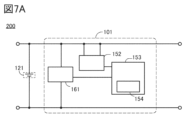
- FIG. 7 shows an example of a secondary battery management system 200. As shown in FIG. The secondary battery management system 200 can operate even at low temperatures.
- the charging circuit 101 shown in FIG. 7A has a differentiator 161 unlike the configuration shown in FIG. 1A.
- Differentiator 161 has a function of outputting a time difference, and can output a time difference when, for example, there is a difference between the terminal voltage at time t1 and the terminal voltage at time t2.
- the differentiator 161 also has a function of converting an analog value into a digital value, that is, a so-called AD converter function. Since such a differentiator 161 has a voltage measurement function, the voltage measurement circuit 151 shown in Examples 1 and 2 can be omitted in Example 3, and other configurations are the same as those in Examples 1 and 2.
- the differentiator 161 and the control circuit 153 are shown in FIG. 7B.
- the differentiator 161 has a sample/hold circuit 300 , a comparator 301 , a DA converter 302 , a successive approximation register 303 , a second control circuit 304 and a clock generation circuit 305 .
- the differentiator 161 can have an AD converter, and the configuration of the AD converter uses any one of a double integration type, a successive approximation type, a ⁇ modulation type, a parallel comparison type (also referred to as a flash type), and a pipeline type. be able to.
- the number of bits of the successive approximation type can be 10 bits or more and 18 bits or less, and the conversion speed is preferably several tens of kHz or more and several MHz or less. Further, the number of bits of the double integration type can be 8 bits or more and 20 bits or less, and the conversion speed is preferably several Hz or more and several kHz or less.
- the differentiator 161 can hold the acquired voltage (analog value) in the sample and hold circuit 300 .
- the sample and hold circuit 300 holds the value while converting the analog value to a digital value.
- An OS transistor can be used as a transistor included in the sample-and-hold circuit 300 .
- An OS transistor is a transistor in which an oxide semiconductor layer is used as an active layer.
- the off-state current value of the OS transistor is, for example, 1 aA (1 ⁇ 10 ⁇ 18 A) or less, 1 zA (1 ⁇ 10 ⁇ 21 A) or less, or 1 yA (1 ⁇ 10 ⁇ 24 A) per ⁇ m channel width at room temperature.
- the off current value of the Si transistor per 1 ⁇ m channel width at room temperature is 1 fA (1 ⁇ 10 ⁇ 15 A) or more and 1 pA (1 ⁇ 10 ⁇ 12 A) or less. Therefore, it can be said that the off-state current of the OS transistor is about ten digits lower than the off-state current of the Si transistor. A transistor with such a small off current is suitable for the sample and hold circuit 300 .
- the value output from the sample/hold circuit 300 is input to the comparator 301 and compared with the data output from the successive approximation register 303 .
- the successive approximation register 303 divides the voltage analog value into at least two, and outputs digital data in which each is assigned to each bit.
- the digital data is converted from digital data to analog data via the DA converter 302 before being input to the comparator 301 .
- Comparator 301 compares the data from sample-and-hold circuit 300 with the data from successive approximation register 303 . If the data match, 0 is output, and if the data do not match, 1 is output. A value of 0 or 1 is output to the second control circuit 304, and a voltage (digital) is output from the successive approximation register 303 when they match. Thus, a voltage converted to a digital value can be obtained.
- Data DataA, data DataB and data DataC are output from the second control circuit 304 to the control circuit 153 .
- Data DataA is, for example, a code (+ or -) indicating whether it is charging or discharging.
- Data DataB is, for example, count data relating to time.
- Data DataC is an error flag. Errors to be flagged include, for example, when the difference in voltage is assigned to 1 bit, and when it is determined to be 2 bits or more.
- the differentiator 161 should be able to output the time between time t1 and time t2. Data corresponding to the time can be output by counting based on a clock signal or the like input to the differentiator 161 .
- the differentiator 161 should be able to output a positive or negative sign.
- the code can be used to distinguish between the voltage during charging and the voltage during discharging. If the distinction is unnecessary, no code need be output.
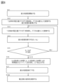
- FIG. 8 shows a flow chart regarding difference processing.
- step S11 difference processing is started.
- step S12 the analog voltage value acquired at an arbitrary time T 0 can be converted into a digital value (D 0 ).
- the voltage value is also added with information about the time when it was acquired.
- the successive approximation type AD converter described above may be used for conversion into digital values.
- This digital value (D 0 ) is used as a reference for difference processing.
- step S13 the analog voltage value acquired after T 1 seconds from an arbitrary time is converted into a digital value (D 1 ).
- the voltage value is also added with information about the time when it was acquired.
- the interval is 50 ms to 1 s, preferably 100 ms to 150 ms, and analog voltage acquisition should be performed periodically at each interval.
- step S14 the reference digital value (D 0 ) and the digital value (D 1 ) after T seconds are subtracted to perform difference processing.
- step S15 it is determined whether the result of the subtraction process is other than zero. If it does not become 0 (corresponding to No in the figure), proceed to the next step, and if it becomes 0 (corresponding to Yes in the figure), return to step S13, acquire a new voltage value, convert it to a digital value, and then , and the digital value (D 0 ) of the reference voltage is repeated.
- step S17 the difference processing ends.
- ⁇ T Based on the time difference ( ⁇ T), a graph relating to battery characteristics such as a voltage differential waveform is calculated, and charging is stopped as shown in FIG. 3 and the like.
- a secondary battery of one embodiment of the present invention preferably includes a positive electrode, a negative electrode, and an electrolyte.
- a positive electrode of one embodiment of the present invention includes a positive electrode active material.
- the positive electrode active material contains lithium, transition metal M, oxygen, and additive element A.
- the positive electrode active material may have a compound oxide (LiMO 2 ) containing lithium and a transition metal M to which an additive element A is added.
- the positive electrode active material to which the additive element A is added is sometimes called a composite oxide.
- cobalt is preferably mainly used as the transition metal M responsible for an oxidation-reduction reaction.
- at least one or more selected from nickel and manganese may be used.
- cobalt is 75 atomic % or more, preferably 90 atomic % or more, and more preferably 95 atomic % or more of the transition metal M contained in the positive electrode active material, it is relatively easy to synthesize and handle, and has excellent cycle characteristics. It has many advantages and is preferable.
- nickel such as lithium nickel oxide (LiNiO 2 ) is included in the transition metal M.
- LiNiO 2 lithium nickel oxide
- the raw material may be cheaper than when cobalt is abundant. Moreover, the charge/discharge capacity per weight may increase, which is preferable.
- the additive element A contained in the positive electrode active material includes magnesium, fluorine, nickel, aluminum, titanium, zirconium, vanadium, iron, manganese, chromium, niobium, arsenic, zinc, silicon, sulfur, phosphorus, boron, bromine, and beryllium. It is preferable to use one or two or more selected.
- the sum of the transition metals among the additive elements A is preferably less than 25 atomic %, more preferably less than 10 atomic %, and even more preferably less than 5 atomic %.
- the positive electrode active material includes lithium cobalt oxide doped with magnesium and fluorine, lithium cobalt oxide doped with magnesium, fluorine and titanium, magnesium, lithium cobalt oxide doped with fluorine and aluminum, and magnesium, fluorine and nickel doped. Lithium cobaltate doped with magnesium, fluorine, nickel and aluminum, and the like.
- additive elements A can further stabilize the crystal structure of the positive electrode active material.
- the positive electrode active material can be substantially free of manganese.
- a positive electrode active material that does not substantially contain manganese has the above advantages of being relatively easy to synthesize, easy to handle, and having excellent cycle characteristics.
- the weight of manganese in the positive electrode active material substantially free of manganese is preferably 600 ppm or less, more preferably 100 ppm or less. Manganese weight can be analyzed using, for example, GD-MS.
- ⁇ Crystal structure> how much lithium that can be intercalated and desorbed remains in the positive electrode active material is indicated by x in the composition formula, for example, x in Li x CoO 2 or x in Li x MO 2 .
- Li x CoO 2 in this specification can be appropriately read as Li x MO 2 .
- x (theoretical capacity ⁇ charge capacity)/theoretical capacity.
- Li 0.2 CoO 2 or x 0.2.
- a small x in Li x CoO 2 means, for example, 0.1 ⁇ x ⁇ 0.24.
- the term “discharging is completed” refers to a state in which the voltage becomes 2.5 V (counter electrode lithium) or less at a current of 100 mA/g, for example.
- the layered rock salt-type composite oxide has a high discharge capacity, has a two-dimensional lithium ion diffusion path, is suitable for lithium ion insertion/extraction reactions, and is excellent as a positive electrode active material for secondary batteries. Therefore, it is particularly preferable that the inside, which occupies most of the volume of the positive electrode active material, has a layered rock salt crystal structure.
- the surface layer portion is a region containing the additive element A, and can function as a barrier film for the positive electrode active material.
- the surface layer portion is, for example, within 50 nm from the surface to the inside of the positive electrode active material, more preferably within 35 nm from the surface to the inside, still more preferably within 20 nm from the surface to the inside, most preferably from the surface to the inside. refers to a region within 10 nm toward
- the surface layer is a region where lithium ions are first desorbed during charging, and is a region where the lithium concentration tends to be lower than in the interior. Therefore, the surface layer portion is likely to be unstable, and can be said to be a region where deterioration of the crystal structure is likely to occur.
- the surface layer can be sufficiently stabilized, even when x in Li x CoO 2 is small, for example, x is 0.24 or less, the internal layered structure consisting of transition metal M and oxygen octahedrons can be made difficult to break. can be done. Furthermore, it is possible to suppress the displacement of the internal layer composed of the transition metal M and the octahedron of oxygen.
- the surface layer portion preferably contains the additive element A, and more preferably contains a plurality of the additive elements A. Further, it is preferable that the concentration of one or more elements selected from the additive element A is higher in the surface layer than in the inside.
- One or two or more of the additive elements A contained in the positive electrode active material preferably have a concentration gradient. Further, it is more preferable that the positive electrode active material has a different distribution depending on the additive element A. For example, it is more preferable that the additive element A has a different depth from the surface of the concentration peak.
- the concentration peak here means the maximum value of the concentration.
- magnesium which is one of the additive elements A
- the layered rock salt type crystal structure can be easily maintained by the presence of magnesium at the lithium site in the surface layer at an appropriate concentration. It is presumed that this is because the magnesium present in the lithium sites functions as a pillar supporting the CoO 2 layers.
- the presence of magnesium can suppress desorption of oxygen around magnesium when x in Li x CoO 2 is, for example, 0.24 or less.
- it can be expected that the presence of magnesium increases the density of the positive electrode active material.
- the magnesium concentration in the surface layer is high, it can be expected that the corrosion resistance to hydrofluoric acid generated by the decomposition of the electrolyte will be improved.
- the amount of magnesium contained in the entire positive electrode active material is appropriate.
- the ratio (Mg/M) of magnesium to the transition metal M (the sum when there are multiple transition metals) in the positive electrode active material of one embodiment of the present invention is 0.25% or more and 5% when M is cobalt.
- the following is preferable, 0.5% or more and 2% or less is more preferable, and about 1% is even more preferable.
- the amount of magnesium contained in the entire positive electrode active material referred to here may be a value obtained by performing elemental analysis of the entire positive electrode active material using, for example, GD-MS, ICP-MS, or the like. It may be based on the value of the raw material composition during the manufacturing process.
- nickel which is one of the additive elements A, can exist at both the transition metal M site and the lithium site.
- the oxidation-reduction potential is lower than that of cobalt, which leads to an increase in discharge capacity, which is preferable.
- the shift of the layered structure composed of the transition metal M and the octahedron of oxygen can be suppressed.
- the change in volume due to charge/discharge is suppressed.
- the elastic modulus increases, that is, it becomes harder. It is presumed that this is because the nickel present in the lithium sites also functions as a pillar supporting the CoO 2 layers. Therefore, the crystal structure can be expected to be more stable in a charged state at a particularly high temperature, for example, 45° C. or higher, which is preferable.
- the amount of nickel contained in the entire positive electrode active material is appropriate.
- the number of nickel atoms in the positive electrode active material is more than 0% of the number of cobalt atoms and is preferably 7.5% or less, preferably 0.05% or more and 4% or less, and 0.1% or more and 2% or less.
- 0.2% or more and 1% or less is more preferable.
- it is preferably more than 0% and 4% or less.
- it is preferably more than 0% and 2% or less.
- 0.05% or more and 7.5% or less is preferable.
- 0.05% or more and 2% or less is preferable.
- 0.1% or more and 7.5% or less is preferable.
- the amount of nickel shown here may be, for example, a value obtained by elemental analysis of the entire positive electrode active material using GD-MS, ICP-MS, etc. may be based on the value of
- aluminum which is one of the additive elements A
- the amount of aluminum contained in the entire positive electrode active material is appropriate.
- the number of aluminum atoms in the entire positive electrode active material is preferably 0.05% or more and 4% or less, preferably 0.1% or more and 2% or less, or 0.3% or more and 1.5%. The following are more preferred. Alternatively, 0.05% or more and 2% or less is preferable. Alternatively, 0.1% or more and 4% or less is preferable.
- the amount of the entire positive electrode active material referred to here may be, for example, a value obtained by performing elemental analysis of the entire positive electrode active material using GD-MS, ICP-MS, or the like, or It may be based on the value of the raw material mix in the process.
- Fluorine which is one of the additive elements A, is a monovalent anion, and if part of the oxygen in the surface layer is substituted with fluorine, the desorption energy of lithium becomes small. This is because the change in the valence of cobalt ions due to desorption of lithium changes from trivalent to tetravalent when fluorine is not present, and from divalent to trivalent when fluorine is present, resulting in different oxidation-reduction potentials. Therefore, when a part of oxygen is replaced with fluorine in the surface layer portion of the positive electrode active material, it can be said that desorption and insertion of lithium ions in the vicinity of fluorine are likely to occur smoothly.
- the positive electrode active material of the present invention when used in a secondary battery, charge/discharge characteristics, current characteristics, etc. can be improved.
- the presence of fluorine in the surface layer portion which is the portion in contact with the electrolytic solution, can effectively improve the corrosion resistance to hydrofluoric acid.
- a fluxing agent flux agent that lowers the melting point of other additive element A sources is used.
- Titanium oxide which is one of the additive elements A, is known to have superhydrophilicity. Therefore, by using a positive electrode active material having titanium oxide in the surface layer portion, wettability to a highly polar solvent may be improved. When used as a secondary battery, the interface between the positive electrode active material and the highly polar electrolyte solution is in good contact, and there is a possibility that an increase in internal resistance can be suppressed.
- phosphorus which is one of the additive elements A, in the surface layer, because it may suppress short circuits when x in Li x CoO 2 is kept small.
- it preferably exists in the surface layer portion as a compound containing phosphorus and oxygen.
- the positive electrode active material contains phosphorus
- hydrogen fluoride generated by decomposition of the electrolytic solution or electrolyte reacts with phosphorus, which may reduce the concentration of hydrogen fluoride in the electrolyte, which is preferable.
- the electrolyte has LiPF 6
- hydrolysis can generate hydrogen fluoride.
- hydrogen fluoride may be generated due to the reaction between polyvinylidene fluoride (PVDF), which is used as a component of the positive electrode, and alkali.
- PVDF polyvinylidene fluoride
- By reducing the concentration of hydrogen fluoride in the electrolyte corrosion of the current collector and/or peeling of the film can be suppressed in some cases.
- the surface layer portion is occupied only by the additive element A and the compound of oxygen, it becomes difficult to intercalate and deintercalate lithium, which is not preferable.
- the surface layer it is not preferable for the surface layer to be occupied only by a structure in which MgO, MgO and NiO(II) are in solid solution, and/or a structure in which MgO and CoO(II) are in solid solution. Therefore, the surface layer must contain at least cobalt, lithium in the discharged state, and a path for intercalation and deintercalation of lithium.
- the concentration of cobalt in the surface layer is preferably higher than that of magnesium.
- the ratio Mg/Co between the number Mg of magnesium atoms and the number Co of cobalt atoms is preferably 0.62 or less.
- the concentration of cobalt in the surface layer portion is higher than that of nickel.
- the concentration of cobalt in the surface layer portion is higher than that of aluminum.
- the concentration of cobalt in the surface layer portion is higher than that of fluorine.
- the positive electrode active material of one embodiment of the present invention has the distribution and/or the crystal structure of the additional element A as described above in the discharged state, the crystal structure when x in Li x CoO 2 is small However, it is different from conventional positive electrode active materials.
- x is small means that 0.1 ⁇ x ⁇ 0.24.
- the positive electrode active material of one embodiment of the present invention shown in FIG. 9 changes in the crystal structure in the discharged state where x in Li x CoO 2 is 1 and in the state where x is 0.24 or less are greater than those in the conventional positive electrode active material. few. More specifically, the shift between the CoO 2 layer when x is 1 and when x is 0.24 or less can be reduced. Also, the change in volume when compared per cobalt atom can be reduced. Therefore, the positive electrode active material of one embodiment of the present invention does not easily lose its crystal structure even when charging and discharging are repeated such that x is 0.24 or less, and excellent cycle characteristics can be achieved.
- the positive electrode active material of one embodiment of the present invention can have a more stable crystal structure than a conventional positive electrode active material when x in Li x CoO 2 is 0.24 or less. Therefore, in the positive electrode active material of one embodiment of the present invention, short-circuiting is unlikely to occur when x in Li x CoO 2 is maintained at 0.24 or less. In such a case, the safety of the secondary battery is further improved, which is preferable.
- FIG. 9 shows the crystal structure of the inside of the positive electrode active material when x in Li x CoO 2 is about 1 and 0.2. Since the inside occupies most of the volume of the positive electrode active material and greatly contributes to charging and discharging, it can be said that displacement of the CoO 2 layer and volume change are the most problematic parts.
- the positive electrode active material has the same R-3mO3 crystal structure as conventional lithium cobaltate.
- the positive electrode active material has a crystal structure different from that of the conventional lithium cobaltate having an H1-3 type crystal structure. .
- the positive electrode active material of one embodiment of the present invention when x is about 0.2 has a crystal structure belonging to the trigonal space group R-3m. It has the same symmetry of CoO2 layer as O3. Therefore, this crystal structure is called an O3' type crystal structure.
- the crystal structure is shown in FIG. 9 labeled R-3m O3′.
- the crystal structure of the O3′ type has the coordinates of cobalt and oxygen in the unit cell as Co (0, 0, 0.5), O (0, 0, x), within the range of 0.20 ⁇ x ⁇ 0.25 can be shown as
- ions of cobalt, nickel, magnesium, etc. occupy six oxygen-coordinated positions. Note that a light element such as lithium may occupy the 4-coordinate position of oxygen in some cases.
- the difference in volume per cobalt atom of the same number in the R-3m(O3) in the discharged state and the O3' type crystal structure is 2.5% or less, more specifically 2.2% or less, typically 1.5%. 8%.
- the positive electrode active material of one embodiment of the present invention when x in Li x CoO 2 is small, that is, when a large amount of lithium is desorbed, the change in crystal structure is suppressed more than in a conventional positive electrode active material. ing. Also, the change in volume when compared per the same number of cobalt atoms is suppressed. Therefore, the crystal structure of the positive electrode active material does not easily collapse even when charging and discharging are repeated such that x becomes 0.24 or less. Therefore, the positive electrode active material is prevented from decreasing in charge/discharge capacity during charge/discharge cycles. In addition, since more lithium can be stably used than conventional positive electrode active materials, the positive electrode active material has a large discharge capacity per weight and per volume. Therefore, by using a positive electrode active material, a secondary battery with high discharge capacity per weight and per volume can be produced.
- the positive electrode active material sometimes has an O3′ type crystal structure when x in Li x CoO 2 is 0.15 or more and 0.24 or less. 27 or less is presumed to have an O3'-type crystal structure.
- x is not necessarily limited to the above range.
- the positive electrode active material does not have to have an O3′-type crystal structure. It may contain other crystal structures, or may be partially amorphous.
- the state in which x in Li x CoO 2 is small can be rephrased as the state of being charged at a high charging voltage.
- a charging voltage of 4.6 V or more based on the potential of lithium metal can be said to be a high charging voltage.
- the charging voltage is expressed based on the potential of lithium metal.
- the positive electrode active material of one embodiment of the present invention is preferable because it can retain a crystal structure having R-3mO3 symmetry even when charged at a high charging voltage, for example, a voltage of 4.6 V or higher at 25°C. can be paraphrased.
- it can be said that it is preferable because it can have an O3' type crystal structure when charged at a higher charging voltage, for example, a voltage of 4.65 V or more and 4.7 V or less at 25°C.
- the positive electrode active material of one embodiment of the invention can have an O3′-type crystal structure in some cases.
- the voltage of the secondary battery is lowered by the potential of the graphite.
- the potential of graphite is about 0.05 V to 0.2 V with respect to the potential of lithium metal. Therefore, in the case of a secondary battery using graphite as a negative electrode active material, it has a similar crystal structure at a voltage obtained by subtracting the potential of graphite from the above voltage.
- the manufacturing process of the positive electrode active material it is preferable to first synthesize a composite oxide containing lithium and a transition metal, and then mix the additive element A source and perform heat treatment.
- the concentration of the additive element A in the surface layer portion is increased. is difficult. Further, after synthesizing a composite oxide containing lithium and transition metal M, if the source of additive element A is only mixed and no heating is performed, the additive element A simply adheres to the composite oxide without forming a solid solution. Without sufficient heating, it is difficult to distribute the additive element A well. Therefore, it is preferable to mix the additive element A source after synthesizing the composite oxide, and to perform the heat treatment. The heat treatment after mixing the additive element A source is sometimes called annealing.
- the annealing temperature is too high, cation mixing will occur, increasing the likelihood that additional element A, such as magnesium, will enter the transition metal M site.
- additional element A such as magnesium
- Magnesium present in the transition metal M site has no effect of maintaining the R-3m layered rock salt type crystal structure when x in Li x CoO 2 is small.
- adverse effects such as reduction of cobalt to bivalence and sublimation or evaporation of lithium may occur.
- a material functioning as a flux with the additive element A source. If the melting point is lower than that of the composite oxide containing lithium and transition metal M, it can be said that the material functions as a flux.
- a material that functions as a flux is preferably a fluorine compound such as lithium fluoride.
- This heating may be referred to as initial heating.
- lithium is desorbed from a part of the surface layer of the composite oxide containing lithium and transition metal M, so that the distribution of additive element A is further improved.
- the initial heating facilitates the distribution of the additive element A to differ due to the following mechanism.
- initial heating desorbs lithium from a part of the surface layer.
- a composite oxide containing lithium having a lithium-deficient surface layer portion and a transition metal M, and an additive element A source such as a nickel source, an aluminum source, and a magnesium source are mixed and heated.
- an additive element A source such as a nickel source, an aluminum source, and a magnesium source
- magnesium is a typical divalent element
- nickel, a transition metal tends to become a divalent ion. Therefore, a rock salt type phase containing Mg 2+ and Ni 2+ and Co 2+ reduced due to lack of lithium is formed in a part of the surface layer.
- nickel easily dissolves into a solid solution in the case of a composite oxide having a layered rock salt type lithium and a transition metal M on the surface layer, and diffuses into the inside. Easy to stay in.
- the Me-O distance in rock salt Ni 0.5 Mg 0.5 O is 0.209 nm
- the Me-O distance in rock salt MgO is 0.211 nm.
- the Me-O distance of spinel-type NiAl2O4 is 0.20125 nm
- the Me- O distance of spinel-type MgAl2O4 is 0.202 nm. is.
- the Me-O distance exceeds 0.2 nm in both cases.
- the bonding distance between metals other than lithium and oxygen is shorter than the above.
- the Al-O distance in layered rock salt LiAlO 2 is 0.1905 nm (Li-O distance is 0.211 nm).
- the Co-O distance in the layered rock salt LiCoO 2 is 0.19224 nm (the Li-O distance is 0.20916 nm).
- the ionic radius of hexacoordinated aluminum is 0.0535 nm
- the ionic radius of hexacoordinated oxygen is 0.0535 nm. 14 nm and their sum is 0.1935 nm.
- the initial heating is expected to have the effect of increasing the crystallinity of the layered rock salt type crystal structure inside.
- the initial heating does not necessarily have to be performed.
- the atmosphere, temperature, time, etc. in other heating steps, such as annealing it may be possible to produce a positive electrode active material having O3′ type when x in Li x CoO 2 is small.
- Example 1 of method for producing positive electrode active material An example of a method for manufacturing a positive electrode active material (Example 1 of a method for manufacturing a positive electrode active material) that can be used as one embodiment of the present invention will be described with reference to FIGS. 10A to 10C. Note that the production method described here is an example of the production method of the positive electrode active material 10 having the characteristics described above in this embodiment.
- Step S11 In step S11 shown in FIG. 10A, a lithium source (Li source) and a cobalt source (Co source) are prepared as starting materials of lithium and transition metal materials, respectively.
- a lithium source Li source
- a cobalt source Co source
- the lithium source it is preferable to use a compound containing lithium.
- a compound containing lithium for example, lithium carbonate, lithium hydroxide, lithium nitrate, lithium fluoride, or the like can be used.
- the lithium source preferably has a high purity, and for example, a material with a purity of 99.99% or higher is preferably used.
- cobalt source it is preferable to use a compound containing cobalt, and for example, cobalt oxide, cobalt hydroxide, or the like can be used.
- the cobalt source preferably has a high purity, for example, a purity of 3N (99.9%) or higher, preferably 4N (99.99%) or higher, more preferably 4N5 (99.995%) or higher, further preferably 5N (99%) or higher. .999%) or higher.
- Impurities in the positive electrode active material can be controlled by using a high-purity material. As a result, the capacity of the secondary battery is increased and/or the reliability of the secondary battery is improved.
- the cobalt source is preferably highly crystalline, eg, having single crystal grains.
- TEM transmission electron microscope
- STEM scanning transmission electron microscope
- HAADF-STEM high angle scattering annular dark field scanning transmission electron microscope
- ABF-STEM Judgment by annular bright field scanning transmission electron microscope
- XRD X-ray diffraction
- the method for evaluating the crystallinity described above can be applied not only to the cobalt source but also to the evaluation of other crystallinities.
- Step S12 the lithium source and the cobalt source are pulverized and mixed to produce a mixed material. Grinding and mixing can be dry or wet. The wet method is preferred because it can be pulverized into smaller pieces.
- a lithium source and a cobalt source with dehydrated acetone with a purity of 99.5% or more and with a water content of 10 ppm or less, followed by pulverization and mixing.
- dehydrated acetone with the above purity, possible impurities can be reduced.
- a ball mill, a bead mill, or the like can be used as means for mixing.
- a ball mill it is preferable to use aluminum oxide balls or zirconium oxide balls as grinding media. Zirconium oxide balls are preferable because they emit less impurities.
- the peripheral speed should be 100 mm/s or more and 2000 mm/s or less in order to suppress contamination from the media. In this embodiment, the peripheral speed is 838 mm/s (rotational speed: 400 rpm, ball mill diameter: 40 mm).
- Step S13 the mixed material is heated. Heating is preferably performed at 800° C. or higher and 1100° C. or lower, more preferably 900° C. or higher and 1000° C. or lower, and even more preferably 950° C. or higher and 1000° C. or lower. If the temperature is too low, decomposition and melting of the lithium source and cobalt source may be insufficient. On the other hand, if the temperature is too high, defects may occur, such as by evaporation of lithium from the lithium source and/or excessive reduction of cobalt. For example, cobalt changes from trivalent to divalent and may induce oxygen defects and the like.
- the heating time may be 1 hour or more and 100 hours or less, preferably 2 hours or more and 20 hours or less.
- the heating rate is preferably 80° C./h or more and 250° C./h or less, although it depends on the reaching temperature of the heating temperature. For example, when heating at 1000° C. for 10 hours, the heating rate is preferably 200° C./h.
- Heating is preferably carried out in an atmosphere with little water such as dry air, for example, an atmosphere with a dew point of -50°C or lower, more preferably -80°C or lower. In this embodiment mode, heating is performed in an atmosphere with a dew point of -93°C.
- concentrations of impurities such as CH 4 , CO, CO 2 , and H 2 in the heating atmosphere be 5 ppb (parts perbillion) or less.
- an atmosphere containing oxygen is preferable.
- the flow rate of dry air is preferably 10 L/min.
- the process by which oxygen continues to be introduced into the reaction chamber and is flowing through the reaction chamber is referred to as flow.
- the heating atmosphere is an atmosphere containing oxygen
- a method that does not flow may be used.
- the reaction chamber may be decompressed and then filled with oxygen to prevent the oxygen from entering or exiting the reaction chamber. This is called purging.
- the reaction chamber may be evacuated to -970 hPa and then filled with oxygen to 50 hPa.
- Cooling after heating may be natural cooling, but it is preferable that the cooling time from the specified temperature to room temperature is within 10 hours or more and 50 hours or less. However, cooling to room temperature is not necessarily required, and cooling to a temperature that the next step allows is sufficient.
- Heating in this step may be performed by a rotary kiln or a roller hearth kiln. Heating by a rotary kiln can be performed while stirring in either a continuous system or a batch system.
- the crucible used for heating is preferably an aluminum oxide crucible.
- a crucible made of aluminum oxide is a material that does not easily release impurities.
- a crucible made of aluminum oxide with a purity of 99.9% is used.
- step S13 After the heating is finished, it may be pulverized and sieved as necessary. When recovering the material after heating, it may be recovered after being moved from the crucible to a mortar.
- a mortar made of aluminum oxide or zirconium oxide Aluminum oxide mortar is a material that does not easily release impurities. Specifically, a mortar made of aluminum oxide with a purity of 90% or higher, preferably 99% or higher is used. Note that the same heating conditions as in step S13 can be applied to the later-described heating process other than step S13.
- Step S14 Through the steps described above, lithium cobaltate (LiCoO 2 ) shown in step S14 shown in FIG. 10A can be synthesized.
- the composite oxide may be produced by the coprecipitation method.
- the composite oxide may be produced by a hydrothermal method.
- step S20 it is preferable to add additive element A as an A source to lithium cobaltate.
- step S20 the details of step S20 of preparing the additive element A as the A source will be described with reference to FIGS. 10B and 10C.
- Step S21 prepares an additive element A.
- the additive element A the additive element described in the previous embodiment, for example, the additive element X and the additive element Y can be used.
- one or more selected from magnesium, fluorine, nickel, aluminum, titanium, zirconium, vanadium, iron, manganese, chromium, niobium, arsenic, zinc, silicon, sulfur, phosphorus and boron can be used.
- One or more selected from bromine and beryllium can also be used.
- FIG. 10B illustrates a case where a magnesium source and a fluorine source are prepared.
- a lithium source may be prepared separately.
- the additive element source can be called a magnesium source.
- a magnesium source magnesium fluoride, magnesium oxide, magnesium hydroxide, magnesium carbonate, or the like can be used. Multiple sources of magnesium may be used.
- the additive element source can be called a fluorine source.
- the fluorine source include lithium fluoride (LiF), magnesium fluoride (MgF 2 ), aluminum fluoride (AlF 3 ), titanium fluoride (TiF 4 ), cobalt fluoride (CoF 2 , CoF 3 ) and fluorine.
- lithium fluoride is preferable because it has a relatively low melting point of 848° C. and is easily melted in a heating step to be described later.
- Magnesium fluoride can be used as both a fluorine source and a magnesium source. Lithium fluoride can also be used as a lithium source. Other lithium sources used in step S21 include lithium carbonate.
- the fluorine source may also be gaseous, such as fluorine ( F2 ), carbon fluoride, sulfur fluoride, or oxygen fluoride ( OF2 , O2F2 , O3F2 , O4F2 , O5F 2 , O 6 F 2 , O 2 F) or the like may be used and mixed in the atmosphere in the heating step described later. Multiple fluorine sources may be used.
- lithium fluoride (LiF) is prepared as a fluorine source
- magnesium fluoride (MgF 2 ) is prepared as a fluorine source and a magnesium source.
- LiF:MgF 2 65:35 (molar ratio)
- the effect of lowering the melting point is maximized.
- the amount of lithium fluoride increases, there is a concern that the amount of lithium becomes excessive and the cycle characteristics deteriorate.
- the neighborhood is a value that is more than 0.9 times and less than 1.1 times that value.
- step S22 shown in FIG. 10B the magnesium source and fluorine source are pulverized and mixed.
- This step can be performed by selecting from the pulverization and mixing conditions described in step S12.
- a heating process may be performed after step S22, if necessary.
- the heating process can be performed by selecting from the heating conditions described in step S13.
- the heating time is preferably 2 hours or longer, and the heating temperature is preferably 800° C. or higher and 1100° C. or lower.
- step S23 shown in FIG. 10B the material pulverized and mixed as described above can be recovered to obtain the additive element A source (A source).
- the additive element A source shown in step S23 has a plurality of starting materials, and can also be called a mixture.
- D50 (median diameter) is preferably 600 nm or more and 20 ⁇ m or less, more preferably 1 ⁇ m or more and 10 ⁇ m or less. Even when one type of material is used as the additive element A source, the D50 (median diameter) is preferably 600 nm or more and 20 ⁇ m or less, more preferably 1 ⁇ m or more and 10 ⁇ m or less.
- Such a pulverized mixture (including the case where one additive element is added) is likely to uniformly adhere to the surface of lithium cobaltate when mixed with lithium cobaltate in a later step. It is preferable that the mixture is uniformly adhered to the surface of the lithium cobalt oxide, since the additive element is easily distributed or diffused uniformly in the surface layer of the composite oxide after heating.
- Step S21> A process different from that in FIG. 10B will be described with reference to FIG. 10C.
- Step S20 shown in FIG. 10C has steps S21 to S23.
- step S21 shown in FIG. 10C four types of additive element sources to be added to lithium cobaltate are prepared. That is, FIG. 10C differs from FIG. 10B in the type of additive element source. Also, in addition to the additive element source, a lithium source may be prepared separately.
- a magnesium source (Mg source), a fluorine source (F source), a nickel source (Ni source), and an aluminum source (Al source) are prepared as four kinds of additive element sources.
- the magnesium source and the fluorine source can be selected from the compounds and the like described with reference to FIG. 10B.
- a nickel source nickel oxide, nickel hydroxide, or the like can be used.
- Aluminum oxide, aluminum hydroxide, and the like can be used as the aluminum source.
- Step S22 and Step S23 are the same as the steps described in FIG. 10B.
- step S31 shown in FIG. 10A lithium cobalt oxide and an additive element source (A source) are mixed.
- the mixing in step S31 is preferably performed under milder conditions than the mixing in step S12.
- the number of revolutions is smaller than that of the mixing in step S12, or that the time is shorter.
- the conditions of the dry method are milder than those of the wet method.
- a ball mill, bead mill, or the like can be used.
- zirconium oxide balls it is preferable to use, for example, zirconium oxide balls as media.
- dry mixing is performed at 150 rpm for 1 hour using a ball mill using zirconium oxide balls with a diameter of 1 mm.
- the mixing is performed in a dry room with a dew point of -100°C or higher and -10°C or lower.
- step S32 of FIG. 10A the mixed materials are recovered to obtain a mixture 903.
- the additive element may be added at other timings, or may be added multiple times. Also, the timing may be changed depending on the element.
- the additive element may be added to the lithium source and the cobalt source at the stage of step S11, that is, at the stage of the starting material of the composite oxide. After that, in step S13, lithium cobaltate having the additive element can be obtained. In this case, there is no need to separate the steps S11 to S14 from the steps S21 to S23. It can be said that it is a simple and highly productive method.
- Lithium cobaltate having a part of the additive element in advance may also be used. For example, if lithium cobaltate to which magnesium and fluorine are added is used, part of steps S11 to S14 and step S20 can be omitted. It can be said that it is a simple and highly productive method.
- lithium cobaltate to which magnesium and fluorine are added in advance is heated in step S15, and then, as in step S20, a magnesium source and a fluorine source, or a magnesium source, a fluorine source, a nickel source, and an aluminum source. may be added.
- step S33 shown in FIG. 10A the mixture 903 is heated. It can be implemented by selecting from the heating conditions described in step S13.
- the heating time is preferably 2 hours or longer.
- the lower limit of the heating temperature in step S33 must be higher than or equal to the temperature at which the reaction between the lithium cobalt oxide and the additive element source proceeds.
- the temperature at which the reaction proceeds may be any temperature at which interdiffusion of the elements of the lithium cobalt oxide and the additive element source occurs, and may be lower than the melting temperature of these materials. Taking an oxide as an example, solid-phase diffusion occurs from 0.757 times the melting temperature T m (Tamman temperature T d ). Therefore, the heating temperature in step S33 may be 500° C. or higher.
- the reaction proceeds more easily when the temperature is higher than or equal to the temperature at which one or more selected from the materials included in the mixture 903 melt.
- the eutectic point of LiF and MgF2 is around 742°C, so the lower limit of the heating temperature in step S33 is preferably 742°C or higher.
- the upper limit of the heating temperature is less than the decomposition temperature (1130° C.) of lithium cobaltate. At temperatures in the vicinity of the decomposition temperature, there is concern that lithium cobaltate will decompose, albeit in a very small amount. Therefore, it is preferably 1000° C. or lower, more preferably 950° C. or lower, and even more preferably 900° C. or lower.
- the heating temperature in step S33 is preferably 500° C. or higher and 1130° C. or lower, more preferably 500° C. or higher and 1000° C. or lower, even more preferably 500° C. or higher and 950° C. or lower, and further preferably 500° C. or higher and 900° C. or lower. preferable.
- the temperature is preferably 742°C or higher and 1130°C or lower, more preferably 742°C or higher and 1000°C or lower, even more preferably 742°C or higher and 950°C or lower, and even more preferably 742°C or higher and 900°C or lower.
- the temperature is preferably 800° C. to 1100° C., preferably 830° C.
- the heating temperature in step S33 is preferably lower than that in step S13.
- some materials such as LiF which is a fluorine source may function as a flux.
- the heating temperature can be lowered to below the decomposition temperature of lithium cobalt oxide, for example, 742° C. or higher and 950° C. or lower, and additional elements such as magnesium are distributed in the surface layer portion to produce a positive electrode active material with good characteristics. can.
- LiF has a lower specific gravity in a gaseous state than oxygen
- LiF may volatilize due to heating, and the volatilization reduces LiF in the mixture 903 .
- the function as a flux is weakened. Therefore, it is necessary to heat while suppressing volatilization of LiF.
- LiF is not used as a fluorine source or the like, there is a possibility that Li on the surface of LiCoO 2 reacts with F in the fluorine source to generate LiF and volatilize. Therefore, even if a fluoride having a higher melting point than LiF is used, it is necessary to similarly suppress volatilization.
- the mixture 903 in an atmosphere containing LiF, that is, to heat the mixture 903 in a state where the partial pressure of LiF in the heating furnace is high. Such heating can suppress volatilization of LiF in the mixture 903 .
- the heating in this step is preferably performed so that the mixtures 903 do not adhere to each other. If the mixture 903 adheres to each other during heating, the contact area with oxygen in the atmosphere is reduced, and the diffusion path of the additive element (eg, fluorine) is blocked. distribution may deteriorate.
- the additive element eg, fluorine
- the additive element for example, fluorine
- a positive electrode active material that is smooth and has less irregularities can be obtained. Therefore, in order to maintain or smoothen the surface after the heating in step S15 in this step, it is preferable that the mixtures 903 do not adhere to each other.
- heating by a rotary kiln it is preferable to heat by controlling the flow rate of the oxygen-containing atmosphere in the kiln. For example, it is preferable to reduce the flow rate of the oxygen-containing atmosphere, or to stop the flow of the atmosphere after first purging the atmosphere and introducing the oxygen atmosphere into the kiln.
- Flowing oxygen may evaporate the fluorine source, which is not preferable for maintaining smoothness of the surface.
- the mixture 903 can be heated in an atmosphere containing LiF, for example, by placing a lid on the container containing the mixture 903 .
- the heating temperature is preferably 600° C. or higher and 950° C. or lower, for example.
- the heating time is, for example, preferably 3 hours or longer, more preferably 10 hours or longer, and even more preferably 60 hours or longer.
- the cooling time after heating is, for example, 10 hours or more and 50 hours or less.
- the heating temperature is preferably 600° C. or higher and 950° C. or lower, for example.
- the heating time is, for example, preferably 1 hour or more and 10 hours or less, more preferably about 2 hours.
- the cooling time after heating is, for example, 10 hours or more and 50 hours or less.
- step S34 shown in FIG. 10A the heated material is recovered and, if necessary, pulverized to obtain positive electrode active material 10 . At this time, it is preferable to further screen the recovered positive electrode active material 10 . Through the above steps, the positive electrode active material 10 having the features described in this embodiment can be manufactured.
- Example 2 of method for producing positive electrode active material Another example of a method for manufacturing a positive electrode active material (Example 2 of a method for manufacturing a positive electrode active material) that can be used as one embodiment of the present invention will be described with reference to FIGS.
- steps S11 to S14 are performed in the same manner as in FIG. 10A to prepare lithium cobalt oxide.
- Step S15 lithium cobaltate is heated in step S15 shown in FIG.
- the heating in step S15 may be called initial heating because it is the first heating for lithium cobalt oxide.
- the heating since the heating is performed before step S20 described below, it may be called preheating or pretreatment.
- lithium is desorbed from a part of the surface layer of the lithium cobaltate as described above.
- the effect of increasing the crystallinity of the interior can be expected.
- the lithium source and/or the cobalt source prepared in step S11 or the like may contain impurities. It is possible to reduce impurities from the finished lithium cobaltate in step 14 by initial heating.
- the effect of increasing the crystallinity of the interior is, for example, the effect of relieving strain, displacement, etc., caused by the difference in shrinkage of the lithium cobalt oxide produced in step S13.
- the initial heating has the effect of making the surface of the lithium cobaltate smooth.
- smooth surface means that the surface is less uneven, the complex oxide is overall rounded, and the corners are rounded.
- the state in which there are few foreign substances adhering to the surface is also called smooth. Foreign matter is considered to be a cause of unevenness, and it is preferable not to allow foreign matter to adhere to the surface.
- the heating time in this step is too short, a sufficient effect cannot be obtained, but if it is too long, the productivity will decrease.
- it can be implemented by selecting from the heating conditions described in step S13.
- the heating temperature in step S15 is preferably lower than the temperature in step S13 in order to maintain the crystal structure of the composite oxide.
- the heating time in step S15 is preferably shorter than the time in step S13 in order to maintain the crystal structure of the composite oxide. For example, heating may be performed at a temperature of 700° C. to 1000° C. for 2 hours to 20 hours.
- a temperature difference may occur between the surface and the inside of the lithium cobalt oxide due to the heating in step S13. Differences in temperature can induce differential shrinkage. It is also considered that the difference in shrinkage occurs due to the difference in fluidity between the surface and the inside due to the temperature difference.
- the energy associated with differential shrinkage imparts internal stress differentials to lithium cobaltate.
- the difference in internal stress is also called strain, and the energy is sometimes called strain energy.
- strain energy is homogenized by the initial heating in step S15.
- the strain energy is homogenized, the strain of lithium cobaltate is relaxed. Along with this, the surface of lithium cobaltate may become smooth. It is also called surface-improved. In other words, after step S15, it is thought that the difference in shrinkage caused in the lithium cobalt oxide is relaxed and the surface of the composite oxide becomes smooth.
- step S15 may be performed. After step S15, it is possible to homogenize the displacement of the composite oxide (relax the displacement of crystals or the like occurring in the composite oxide, or align the crystal grains). As a result, the surface of the composite oxide may become smooth.
- lithium cobalt oxide having a smooth surface When lithium cobalt oxide having a smooth surface is used as a positive electrode active material, deterioration during charging and discharging as a secondary battery is reduced, and cracking of the positive electrode active material can be prevented.
- step S14 previously synthesized lithium cobaltate may be used. In this case, steps S11 to S13 can be omitted. By performing step S15 on previously synthesized lithium cobalt oxide, lithium cobalt oxide with a smooth surface can be obtained.
- steps S20 to S33 are performed in the same manner as in FIG. 10A to obtain the positive electrode active material 10 of step S34.
- 10B and 10C can be referred to for details of step S20 in FIG.
- the positive electrode active material 10 having the features described in this embodiment can be manufactured.
- Example 3 of method for producing positive electrode active material Another example of a method for manufacturing a positive electrode active material (Example 3 of a method for manufacturing a positive electrode active material) that can be used as one embodiment of the present invention will be described with reference to FIGS.
- Example 3 of the method for producing a positive electrode active material is different from the above-described examples 1 and 2 of the method for producing a positive electrode active material in terms of the number of times the additive element is added and the mixing method. The description of Examples 1 and 2 can be applied.
- steps S11 to S15 are performed in the same manner as in FIG. 10A to prepare lithium cobalt oxide that has undergone initial heating.
- Step S20a additive element A is added to lithium cobalt oxide that has undergone initial heating. Step S20a will be described also with reference to FIG. 13A.
- a first additive element source (A1 source) is prepared.
- the A1 source can be selected from the additive elements A described in step S21 shown in FIG. 10B.
- the additive element A1 one or more selected from magnesium, fluorine, and calcium can be used.
- FIG. 13A illustrates a case where a magnesium source (Mg source) and a fluorine source (F source) are used as the additive element A1.
- Steps S21 to S23 shown in FIG. 13A can be manufactured under the same conditions as steps S21 to S23 shown in FIG. 10B.
- an additive element source (A1 source) can be obtained in step S23.
- steps S31 to S33 shown in FIG. 12 can be manufactured under the same conditions as steps S31 to S33 shown in FIG. 10A.
- Step S34a Next, the material heated in step S33 is recovered, and lithium cobaltate having the additive element A1 is produced.
- the composite oxide (first composite oxide) in step S14 it is also called a second composite oxide.
- Step S40 In step S40 shown in FIG. 12, a second additive element source is added. Step S40 will also be described with reference to FIGS. 13B and 13C.
- a second additive element source (A2 source) is prepared.
- the A2 source can be selected from the additive elements A described in step S21 shown in FIG. 10B.
- the additional element A2 any one or more selected from nickel, titanium, boron, zirconium, and aluminum can be suitably used.
- FIG. 13B illustrates a case where nickel and aluminum are used as the additive element A2.
- Steps S41 to S43 shown in FIG. 13B can be manufactured under the same conditions as steps S21 to S23 shown in FIG. 10B. As a result, an additive element source (A2 source) can be obtained in step S43.
- A2 source additive element source
- Steps S41 to S43 shown in FIG. 13C are a modification of FIG. 13B.
- a nickel source (Ni source) and an aluminum source (Al source) are prepared in step S41 shown in FIG. 13C, and pulverized independently in step S42a.
- a plurality of second additive element sources (A2 sources) are prepared in step S43.
- the step of FIG. 13C differs from that of FIG. 13B in that the additive elements are independently pulverized in step S42a.
- steps S51 to S53 shown in FIG. 12 can be manufactured under the same conditions as steps S31 to S33 shown in FIG. 10A.
- the conditions of step S53 regarding the heating process may be a lower temperature and a shorter time than those of step S33.
- Step S54 Next, in step S54 shown in FIG. 12, the heated material is collected and, if necessary, pulverized to obtain positive electrode active material 10 .
- the positive electrode active material 10 having the features described in this embodiment can be manufactured.
- the additive elements to lithium cobaltate are introduced separately into a first additive element A1 and a second additive element A2.
- the profile of each additive element in the depth direction can be changed. For example, it is possible to profile the first additive element so that the concentration is higher in the surface layer than in the inside, and to profile the second additive element so that the concentration is higher inside than in the surface layer. .
- a negative electrode of one embodiment of the present invention includes a negative electrode active material.
- a negative electrode active material a material capable of reacting with carrier ions of a secondary battery, a material capable of inserting and extracting carrier ions, a material capable of alloying reaction with a metal that serves as carrier ions, and a material serving as carrier ions. It is preferable to use a material capable of dissolving and depositing metal.
- Carbon materials such as graphite, graphitizable carbon, non-graphitizable carbon, carbon nanotube, carbon black, and graphene can be used as the negative electrode active material.
- the negative electrode active material for example, a material containing one or more elements selected from silicon, lithium, tin, gallium, aluminum, germanium, lead, antimony, bismuth, silver, zinc, cadmium, and indium can be used.
- phosphorus, arsenic, boron, aluminum, gallium, or the like may be added as an impurity element to silicon to lower the resistance.
- a material containing silicon for example, a material represented by SiO x (where x is preferably less than 2, more preferably 0.5 or more and 1.6 or less) can be used.
- a material containing silicon for example, a form having a plurality of crystal grains in one particle can be used.
- a form in which one grain has one or more silicon crystal grains can be used.
- the one particle may have silicon oxide around the silicon crystal grain.
- the silicon oxide may be amorphous.
- Li 2 SiO 3 and Li 4 SiO 4 can be used as compounds containing silicon.
- Li 2 SiO 3 and Li 4 SiO 4 may each be crystalline or amorphous.
- Compounds containing silicon can be analyzed using NMR, XRD, Raman spectroscopy, and the like.
- a lithium foil may be prepared as the negative electrode containing lithium.
- Lithium foil can be made by sputtering, CVD, or vapor deposition and is sometimes referred to as a lithium layer or lithium metal.
- examples of materials that can be used for the negative electrode active material include oxides containing one or more elements selected from titanium, niobium, tungsten, and molybdenum.
- a plurality of the metals, materials, compounds, and the like shown above can be used in combination as the negative electrode active material.
- the negative electrode active material of one embodiment of the present invention may contain fluorine in the surface layer portion.
- fluorine By having the halogen in the surface layer of the negative electrode active material, it is possible to suppress a decrease in charge-discharge efficiency. In addition, it is considered that the reaction with the electrolyte on the surface of the active material is suppressed.
- At least part of the surface of the negative electrode active material of one embodiment of the present invention is covered with a halogen-containing region in some cases.
- the region may be, for example, membranous. Fluorine is particularly preferred as halogen.
- the negative electrode may be a negative electrode that does not have a negative electrode active material at the end of the production of the battery.
- the negative electrode without a negative electrode active material for example, a negative electrode having only a negative electrode current collector at the end of battery production, lithium ions desorbed from the positive electrode active material by charging the battery are deposited on the negative electrode current collector.
- a negative electrode deposited as lithium metal to form a negative electrode active material layer can be used.
- a battery using such a negative electrode is sometimes called a negative electrode-free (anode-free) battery, a negative electrode-less (anode-less) battery, or the like.
- a film for uniform deposition of lithium may be provided on the negative electrode current collector.
- a film for uniform deposition of lithium for example, a solid electrolyte having lithium ion conductivity can be used.
- the solid electrolyte a sulfide grain-based solid electrolyte, an oxide-based solid electrolyte, a polymer-based solid electrolyte, or the like can be used.
- the polymer solid electrolyte is suitable as a film for uniform deposition of lithium because it is relatively easy to form a uniform film on the negative electrode current collector.
- a metal film forming an alloy with lithium can be used as a film for uniformizing deposition of lithium.
- a magnesium metal film for example, can be used as the metal film forming an alloy with lithium. Since lithium and magnesium form a solid solution in a wide composition range, it is suitable as a film for uniform deposition of lithium.
- a negative electrode current collector having unevenness can be used.
- the concave portions of the negative electrode current collector become cavities in which lithium contained in the negative electrode current collector is easily deposited, so that when lithium is deposited, it is suppressed to form a dendrite shape. can do.
- the electrolyte preferably contains a solvent and a metal salt that serves as carrier ions.
- the metal salts are referred to as lithium salts.
- Preferred electrolyte solvents are aprotic organic solvents such as ethylene carbonate (EC), propylene carbonate (PC), butylene carbonate, chloroethylene carbonate, vinylene carbonate, ⁇ -butyrolactone, ⁇ -valerolactone, dimethyl carbonate ( DMC), diethyl carbonate (DEC), ethyl methyl carbonate (EMC), methyl formate, methyl acetate, ethyl acetate, methyl propionate, ethyl propionate, propyl propionate, methyl butyrate, 1,3-dioxane, 1,4- Dioxane, dimethoxyethane (DME), dimethyl sulfoxide, diethyl ether, methyl diglyme, ace
- EC is a cyclic carbonate and has a high dielectric constant, so it has the effect of promoting the dissociation of lithium salts.
- the organic solvent specifically described as one aspect of the present invention preferably further contains EMC and DMC instead of EC alone.
- EMC is a chain carbonate, has the effect of lowering the viscosity of the electrolytic solution, and has a freezing point of -54°C.
- DMC is also a chain carbonate, has the effect of lowering the viscosity of the electrolytic solution, and has a freezing point of -43°C.
- EC, EMC, and DMC having such physical properties are used in a volume ratio of x: y: 100-x-y (where 5 ⁇ x ⁇ 35), with the total content of these three organic solvents being 100 vol%. , and 0 ⁇ y ⁇ 65.)
- An electrolyte prepared using an organic solvent mixed so as to satisfy the condition is preferable because the solidification point can be ⁇ 40° C. or lower.
- Ionic liquids normal temperature molten salts
- the internal temperature rises due to internal short-circuiting or overcharging of the secondary battery.
- the secondary battery can be prevented from exploding or catching fire.
- Ionic liquids consist of cations and anions, including organic cations and anions.
- Organic cations used in the electrolyte include aliphatic onium cations such as quaternary ammonium cations, tertiary sulfonium cations and quaternary phosphonium cations, and aromatic cations such as imidazolium cations and pyridinium cations.
- anions used in the electrolyte include monovalent amide anions, monovalent methide anions, fluorosulfonate anions, perfluoroalkylsulfonate anions, tetrafluoroborate anions, perfluoroalkylborate anions, hexafluorophosphate anions, Alternatively, perfluoroalkyl phosphate anions and the like can be mentioned.
- Examples of salts dissolved in the above solvent include LiPF 6 , LiClO 4 , LiAsF 6 , LiBF 4 , LiAlCl 4 , LiSCN, LiBr, LiI, Li 2 SO 4 , Li 2 B 10 Cl 10 , Li 2 B 12 Cl12 , LiCF3SO3 , LiC4F9SO3 , LiC ( CF3SO2 ) 3 , LiC( C2F5SO2 ) 3 , LiN( CF3SO2 ) 2 , LiN ( C4F9 SO 2 )(CF 3 SO 2 ), LiN(C 2 F 5 SO 2 ) 2 or the like can be used alone, or two or more thereof can be used in any combination and ratio.
- the electrolyte used in the secondary battery it is preferable to use a highly purified electrolytic solution containing only a small amount of particulate matter or elements other than constituent elements of the electrolyte (hereinafter also simply referred to as “impurities”).
- impurities a highly purified electrolytic solution containing only a small amount of particulate matter or elements other than constituent elements of the electrolyte (hereinafter also simply referred to as “impurities”).
- the weight ratio of impurities to the electrolyte is preferably 1% or less, preferably 0.1% or less, and more preferably 0.01% or less.
- the electrolyte includes vinylene carbonate (VC), propanesultone (PS), tert-butylbenzene (TBB), fluoroethylene carbonate (FEC), lithium bis(oxalate) borate (LiBOB), and dinitriles such as succinonitrile and adiponitrile.
- Additives such as chemical compounds may be added.
- the concentration of the material to be added may be, for example, 0.1 wt % or more and 5 wt % or less with respect to the entire solvent.
- VC or LiBOB are particularly preferred because they tend to form good coatings.
- a solution containing a solvent and a salt serving as carrier ions is sometimes called an electrolytic solution.
- a polymer gel electrolyte obtained by swelling a polymer with an electrolytic solution may also be used.
- the safety against leakage and the like is enhanced. Also, the thickness and weight of the secondary battery can be reduced.
- silicone gel acrylic gel, acrylonitrile gel, polyethylene oxide gel, polypropylene oxide gel, fluorine polymer gel, and the like can be used.
- polymers examples include polymers having a polyalkylene oxide structure such as polyethylene oxide (PEO), PVDF, polyacrylonitrile, and copolymers containing them.
- PEO polyethylene oxide
- PVDF-HFP which is a copolymer of PVDF and hexafluoropropylene (HFP)
- the polymer formed may also have a porous geometry.
- a solid electrolyte containing an inorganic material can be used as the electrolyte.
- sulfide-based solid electrolytes, oxide-based solid electrolytes, halide-based solid electrolytes, and the like can be used.
- a solid electrolyte having a polymer material such as PEO (polyethylene oxide) can be used.
- Sulfide-based solid electrolytes include thiolysicone - based ( Li10GeP2S12 , Li3.25Ge0.25P0.75S4 , etc. ) , sulfide glass ( 70Li2S , 30P2S5 , 30Li2 S.26B2S3.44LiI , 63Li2S.36SiS2.1Li3PO4 , 57Li2S.38SiS2.5Li4SiO4 , 50Li2S.50GeS2 , etc. ) , sulfide crystallized glass ( Li7 P 3 S 11 , Li 3.25 P 0.95 S 4 etc.).
- a sulfide-based solid electrolyte has advantages such as being a material with high conductivity, being able to be synthesized at a low temperature, and being relatively soft so that a conductive path is easily maintained even after charging and discharging.
- oxide-based solid electrolytes examples include materials having a perovskite-type crystal structure (La2 /3- xLi3xTiO3 , etc.), materials having a NASICON-type crystal structure ( Li1- xAlxTi2 -x ( PO4 ) 3, etc.), materials having a garnet- type crystal structure ( Li7La3Zr2O12 , etc. ), materials having a LISICON-type crystal structure ( Li14ZnGe4O16 , etc. ), LLZO ( Li7La3Zr2O 12 ), oxide glass ( Li3PO4 - Li4SiO4 , 50Li4SiO4 , 50Li3BO3 , etc. ), oxide crystallized glass ( Li1.07Al0.69Ti1.46 ( PO4 ) 3 , Li 1.5 Al 0.5 Ge 1.5 (PO 4 ) 3 etc.). Oxide-based solid electrolytes have the advantage of being stable in the atmosphere.
- Halide-based solid electrolytes include LiAlCl 4 , Li 3 InBr 6 , LiF, LiCl, LiBr, LiI, and the like. Composite materials in which pores of porous aluminum oxide or porous silica are filled with these halide-based solid electrolytes can also be used as solid electrolytes.
- Li1 + xAlxTi2 -x ( PO4 ) 3 (0[x[1) (hereinafter referred to as LATP) having a NASICON-type crystal structure is used in the secondary battery of one embodiment of the present invention, which includes aluminum and titanium. Since it contains an element that the positive electrode active material to be used may have, a synergistic effect can be expected to improve the cycle characteristics, which is preferable. Also, an improvement in productivity can be expected by reducing the number of processes.
- the NASICON-type crystal structure is a compound represented by M 2 (AO 4 ) 3 (M: transition metal, A: S, P, As, Mo, W, etc.), and MO 6 It has a structure in which octahedrons and AO 4 tetrahedrons share vertices and are arranged three-dimensionally.
- the charging voltage of the secondary battery is higher than 4.2V. is preferred, and higher than 4.3V is more preferred. Also, the charging voltage of the secondary battery is, for example, 4.8V or less, 4.7V or less, or 4.65V or less.
- the secondary battery When the secondary battery has a compound represented by the chemical formula LiMO 2 in which 40 mol % or more of M is nickel as the positive electrode active material, and graphite as the negative electrode active material, the secondary battery is preferably higher than 4.1V, more preferably higher than 4.2V. Also, the charging voltage of the secondary battery is, for example, 4.8 V or less, 4.7 V or less, or 4.65 V or less.
- the charging capacity is, for example, 200 mAh/g or more, more preferably 210 mAh/g or more, and still more preferably 215 mAh/g or more (45° C. , at a charge rate of 0.5C).
- FIG. 14 An example of an external view of an example of a laminated secondary battery 121 is shown in FIG. FIG. 14 has a positive electrode layer 106 , a negative electrode layer 107 , a separator 103 , an exterior body 509 , a positive electrode lead electrode 510 and a negative electrode lead electrode 511 .
- FIG. 15A shows an external view of the positive electrode layer 106 and the negative electrode layer 107.
- the positive electrode layer 106 has a structure in which a positive electrode active material layer is formed on a positive electrode current collector.
- the positive electrode layer 106 has a region where the positive electrode current collector is partially exposed (hereinafter referred to as a tab region), and a positive electrode tab 501 is provided in this region.
- the negative electrode layer 107 has a structure in which a negative electrode active material layer is formed on a negative electrode current collector. Further, the negative electrode layer 107 has a region where the negative electrode current collector is partially exposed, that is, a tab region, and a negative electrode tab 504 is provided in this region.
- a negative electrode layer 107, a separator 103 and a positive electrode layer 106 are laminated.
- an example is shown in which five sets of negative electrodes and four sets of positive electrodes are used.
- the tab regions of the positive electrode layer 106 are joined together, and the positive electrode lead electrode 510 is joined to the tab region of the outermost positive electrode.
- For joining for example, ultrasonic welding or the like may be used.
- bonding between the tab regions of the negative electrode layer 107 and bonding of the negative electrode lead electrode 511 to the tab region of the outermost negative electrode are performed.
- the layered body shown in FIG. 15B is arranged on the armor 509, and the armor 509 is bent at the portion indicated by the broken line. After that, the outer peripheral portion of the exterior body 509 is adhered.
- the area used for gluing is referred to as the gluing area.
- thermocompression bonding or the like may be used for joining.
- the electrolytic solution into the exterior body 509 through an inlet provided in the exterior body 509 . It is preferable to introduce the electrolytic solution under a reduced pressure atmosphere or an inert atmosphere. And finally, the inlet is joined. In this manner, the laminated secondary battery 121 can be manufactured.
- This embodiment can be used in combination with other embodiments.
- the secondary battery 121 can be bent after forming the above-described laminated secondary battery 121 . That is, the secondary battery 121 has flexibility.
- FIG. 16A shows secondary battery 121 in a bent configuration.
- FIG. 16A shows a configuration in which a secondary battery 121 having a positive electrode layer 106, a separator 103, and a negative electrode layer 107 is bent toward the positive electrode layer 106 side.
- the secondary battery 121 may have a curved shape toward the negative electrode layer 107 .
- the curved shape includes a shape having an arc-shaped portion in one cross section of the secondary battery 121 .
- the secondary battery 121 also has an exterior and the like.
- the exterior body described in the above embodiment can follow a curved shape.
- the secondary battery 121 has a layer closer to the center of curvature 1800, for example, the radius of curvature 1802 of the positive electrode layer 106 is larger than the radius of curvature 1804 of the layer farther from the center of curvature 1800, such as the negative electrode layer 107. become smaller.
- the thickness of the layer having a small radius of curvature, for example, the positive electrode layer 106 is preferably smaller than that of the negative electrode layer 107 .
- FIG. 16B when the secondary battery 121 is bent as shown in FIG. 16A, compressive stress is applied to the surface of the positive electrode layer 106 and tensile stress is applied to the surface of the negative electrode layer 107 as indicated by arrows.
- a layer with a smaller radius of curvature, such as the positive electrode layer 106 may be thicker than the negative electrode layer 107 in order to relieve compressive stress.
- the recesses and protrusions are formed on the surface of the exterior body 1805 and are like patterns. Note that, as can be seen from a cross section of the exterior body 1805, when the exterior body is provided with a convex portion, a recessed portion is also formed at the same time, and when the exterior body is provided with a recessed portion, the convex portion is also formed at the same time. That is, it is not necessary to form both recesses and protrusions on the exterior body, and by providing one of them, the other is formed at the same time.
- the armor 1805 can relieve the compressive stress and tensile stress described above. That is, the secondary battery 121 can be deformed within a range in which the radius of curvature of the outer package on the side closer to the center of curvature is 30 mm or more, preferably 10 mm or more.
- a bonding region 1807 is a region where the exterior body 1805 is bonded by thermocompression bonding or the like.
- An adhesive layer 1803 may be positioned between the outer bodies 1805 in the adhesive region 1807 .
- concave portions or convex portions provided on the upper and lower sides of the exterior body 1805 may overlap each other. Since the concave portions or the convex portions overlap each other, the concave portions or the convex portions may be formed in the exterior body 1805 again when the exterior body is adhered. Adhesion strength can be increased by such a configuration.
- a region 1808 that is an end portion of the outer package 1805 and is not the adhesive region 1807 shows the secondary battery 121 having a space 1810 .
- a region 1808 that is an end portion of the outer package 1805 and is not the adhesive region 1807 shows the secondary battery 121 having the electrolyte 108 . Since the adhesive strength of the exterior body 1805 is high, the electrolytic solution 108 does not leak from the exterior body 1805 . 17B may have a space if it is not filled with the electrolyte 108.
- the shape of the curved secondary battery 121 is not limited to a simple arc shape in a cross-sectional view, and may be a shape partially having an arc shape.
- This embodiment can be used in combination with other embodiments.
- the secondary battery management system preferably has the charging circuit of one embodiment of the present invention.
- the charging circuit of one embodiment of the present invention preferably includes components included in the charging circuit described in any of the above embodiments.
- the charging circuit of one embodiment of the present invention may include a circuit having a function of converting voltage, current, or the like of supplied power. Examples of circuits that have the function of converting the voltage, current, etc. of electric power include regulators, step-down circuits, step-up circuits, circuits that have the function of converting AC power to DC power, modulation circuits, demodulation circuits, amplifier circuits, and the like. .
- FIG. 18 shows a block diagram of a vehicle having a motor.
- the electric vehicle is provided with first batteries 1301a and 1301b as secondary batteries for main driving, and a second battery 1311 that supplies power to an inverter 1312 that starts the motor 1304 .
- the second battery 1311 is also called cranking battery or starter battery.
- the second battery 1311 only needs to have a high output and does not need a large capacity so much, and the capacity of the second battery 1311 is smaller than that of the first batteries 1301a and 1301b.
- This embodiment mode shows an example in which two first batteries 1301a and 1301b are connected in parallel, but three or more batteries may be connected in parallel. Further, if the first battery 1301a can store sufficient electric power, the first battery 1301b may be omitted. A large amount of electric power can be extracted by forming a battery pack including a plurality of secondary batteries. A plurality of secondary batteries may be connected in parallel, may be connected in series, or may be connected in series after being connected in parallel. A plurality of secondary batteries is also called an assembled battery.
- a secondary battery for vehicle has a service plug or a circuit breaker that can cut off high voltage without using a tool in order to cut off power from a plurality of secondary batteries.
- the power of the first batteries 1301 a and 1301 b is mainly used to rotate the motor 1304 , but is also used to power the 42V system (high voltage system) in-vehicle components (electric power steering 1307 , heater 1308 ) via the DCDC circuit 1306 . , defogger 1309).
- the first battery 1301a is also used to rotate the rear motor 1317 when the rear wheel has the rear motor 1317 .
- the second battery 1311 supplies power to 14V system (low voltage system) in-vehicle components (audio 1313, power window 1314, lamps 1315, etc.) via the DCDC circuit 1310 .
- 14V system low voltage system
- in-vehicle components audio 1313, power window 1314, lamps 1315, etc.
- the first batteries 1301a and 1301b mainly supply power to 42V system (high voltage system) in-vehicle equipment, and the second battery 1311 supplies power to 14V system (low voltage system) in-vehicle equipment.
- a lead-acid battery is often adopted as the second battery 1311 because of its cost advantage.
- the second battery 1311 may use a lead-acid battery, an all-solid battery, or an electric double layer capacitor.
- regenerated energy from the rotation of tire 1316 is sent to motor 1304 via gear 1305 and charged to second battery 1311 from motor controller 1303 or battery controller 1302 .
- the battery controller 1302 charges the first battery 1301 a through the control circuit unit 1321 .
- the battery controller 1302 charges the first battery 1301 b through the control circuit unit 1321 .
- the battery controller 1302 can set the charging voltage and charging current of the first batteries 1301a and 1301b.
- the battery controller 1302 can set charging conditions according to the charging characteristics of the secondary battery to be used and perform rapid charging.
- the charging circuit of one embodiment of the present invention can be used as the battery controller 1302 . Between the motor 1304 and the battery controller 1302, a circuit having a function of converting the voltage, current, etc. of electric power may be provided.
- the charging circuit of one embodiment of the present invention as the battery controller 1302, the reliability of the first batteries 1301a and 1301b can be improved while the charge capacity of the first batteries 1301a and 1301b is increased. Since the charge capacities of the first batteries 1301a and 1301b can be increased, the travel distance of the electric vehicle can be increased. In addition, since deterioration of the first batteries 1301a and 1301b can be suppressed, it is possible to reduce the frequency of battery replacement in the electric vehicle. Moreover, since the reliability of the first batteries 1301a and 1301b can be improved, the safety of the electric vehicle can be improved.
- a next-generation clean energy vehicle such as a hybrid vehicle (HV), an electric vehicle (EV), or a plug-in hybrid vehicle (PHV) can be realized by installing the secondary battery management system of one embodiment of the present invention in a vehicle.
- agricultural machinery such as electric tractors, motorized bicycles including electric assisted bicycles, motorcycles, electric wheelchairs, electric carts, small or large ships, submarines, aircraft such as fixed or rotary wing aircraft, rockets, artificial satellites
- a secondary battery can also be mounted on a transportation vehicle such as a space probe, a planetary probe, or a spacecraft.
- a vehicle 2001 shown in FIG. 19A is an electric vehicle that uses an electric motor as a power source for running. Alternatively, it is a hybrid vehicle in which an electric motor and an engine can be appropriately selected and used as power sources for running.
- the secondary battery is installed at one or more locations.
- a car 2001 shown in FIG. 19A has a secondary battery management system according to one embodiment of the present invention.
- the secondary battery management system includes the charging circuit of one embodiment of the present invention and the first battery 1301a illustrated in FIG.
- the secondary battery management system may have a plurality of secondary batteries connected in series as an assembled battery. The assembled battery is electrically connected to the charging circuit of one embodiment of the present invention.
- the secondary battery management system of the automobile 2001 can receive power from an external power supply facility by a plug-in system, a contactless power supply system, or the like.
- a plug-in system for power supply, it is possible to use a connector standard according to a predetermined method such as CHAdeMO (registered trademark) or Combo, and a power supply method.
- Power may be supplied from a charging station provided in a commercial facility, or may be supplied from a household power source.
- a signal to stop charging can be given to the charging station via the control circuit included in the charging circuit of one embodiment of the present invention.
- the charging circuit of one embodiment of the present invention may be applied to a charging station.
- a charging station may have at least some of the components of the charging circuit of one aspect of the invention, such as a control circuit of the charging circuit of one aspect of the invention.
- the automobile 2001 preferably has a function of converting AC power into DC power via a conversion device such as an ACDC converter.
- converted DC power is supplied to the secondary battery management system.
- a power receiving device can be mounted on a vehicle to receive power from a power transmitting device on the ground in a contactless manner.
- power can be supplied not only while the vehicle is stopped but also while the vehicle is running by incorporating a power transmission device into the road or the outer wall.
- power may be transmitted and received between two vehicles.
- a solar battery may be provided on the exterior of the vehicle to receive power while the vehicle is stopped or running. An electromagnetic induction method or a magnetic resonance method can be used for such contactless power supply.
- FIG. 19B shows a large transport vehicle 2002 with electrically controlled motors as an example of a transport vehicle.
- the secondary battery module of the transportation vehicle 2002 has a maximum voltage of 170 V, for example, a four-cell unit of secondary batteries of 3.5 V or more and 4.7 V or less, and 48 cells connected in series.
- a secondary battery management system 2201 includes a charging circuit of one embodiment of the present invention and a secondary battery module. Except for the number of secondary batteries constituting the secondary battery module, the function is the same as that of FIG. 19A, so the description is omitted.
- FIG. 19C shows, as an example, a large transport vehicle 2003 with electrically controlled motors.
- Transport vehicle 2003 has secondary battery management system 2202 .
- a secondary battery management system 2202 includes a charging circuit of one embodiment of the present invention and a secondary battery module.
- a maximum voltage of 600V is obtained by connecting in series one hundred or more secondary batteries of 3.5V to 4.7V. Except for the number of secondary batteries constituting the secondary battery module, the function is the same as that of FIG. 19A, so the description is omitted.
- FIG. 19D shows an aircraft 2004 having an engine that burns fuel as an example. Since the aircraft 2004 shown in FIG. 19D has wheels for takeoff and landing, it can be said to be part of a transportation vehicle, and a secondary battery module is configured by connecting a plurality of secondary batteries. It has a secondary battery management system 2203 including a charging circuit of one embodiment of the invention.
- the secondary battery module of the aircraft 2004 has a maximum voltage of 32V, for example, eight 4V secondary batteries connected in series. Except for the number of secondary batteries constituting the secondary battery module of the secondary battery management system 2203, the functions are the same as those in FIG. 19A, so the description is omitted.
- FIG. 19E shows a transport vehicle 2005 transporting freight as an example.
- Transport vehicle 2005 has secondary battery management system 2204 .
- a secondary battery management system 2204 includes a charging circuit of one embodiment of the present invention and a secondary battery module.
- the transportation vehicle 2005 has a motor controlled by electricity, and performs various tasks by supplying power from the secondary battery that constitutes the secondary battery module of the secondary battery management system 2204 .
- the transportation vehicle 2005 is not limited to being operated by a human as a driver, and can be operated unmanned by CAN communication or the like.
- FIG. 19E shows a forklift, it is not particularly limited, and can be applied to industrial machines that can be operated by CAN communication or the like, such as automatic transportation machines, work robots, or small construction machines.
- a secondary battery management system can be installed.
- the house shown in FIG. 20A has a secondary battery management system 2612 and solar panels 2610 .
- the secondary battery management system 2612 has, for example, an assembled battery made up of a plurality of secondary batteries.
- the secondary battery management system 2612 is electrically connected to the solar panel 2610 via wiring 2611 and the like.
- the secondary battery management system 2612 has a charging circuit of one embodiment of the present invention. Electric power obtained from the solar panel 2610 can be charged to the secondary battery management system 2612 through a charging circuit.
- the secondary battery management system 2612 and the ground-mounted charging device 2604 may be electrically connected.
- a signal for notifying the charging device 2604 to stop charging can be given via the control circuit included in the charging circuit.
- the charging circuit of one embodiment of the present invention may be applied to the charging device 2604 .
- the charging device 2604 may comprise at least some of the components of the charging circuit of one aspect of the invention, such as control circuitry of the charging circuit of one aspect of the invention.
- the electric power stored in the secondary battery management system 2612 can charge the secondary battery of the vehicle 2603 via the charging device 2604 .
- the secondary battery management system 2612 is preferably installed in the underfloor space. By installing in the space under the floor, the space above the floor can be effectively used. Alternatively, the secondary battery management system 2612 may be installed on the floor.
- the power stored in the secondary battery management system 2612 can also be supplied to other electronic devices in the house. Therefore, even when power cannot be supplied from a commercial power supply due to a power failure or the like, the use of the electronic device is possible by using the secondary battery management system 2612 as an uninterruptible power supply.
- FIG. 20B shows an example of a secondary battery management system according to one aspect of the present invention.
- a secondary battery management system 791 including a large secondary battery and a charging circuit of one embodiment of the present invention is installed.
- a control device 790 is installed in the secondary battery management system 791.
- the control device 790 includes a distribution board 703, a power storage controller 705 (also referred to as a control device), a display 706, and a router 709 by wiring. and are electrically connected to
- Power is sent from commercial power supply 701 to distribution board 703 via drop wire attachment 710 . Also, power is sent to the distribution board 703 from the secondary battery management system 791 and the commercial power supply 701, and the distribution board 703 transmits the sent power via an outlet (not shown). , general load 707 and storage system load 708 .
- a general load 707 is, for example, an electronic device such as a television or a personal computer
- a power storage system load 708 is, for example, an electronic device such as a microwave oven, refrigerator, or air conditioner.
- the power storage controller 705 has a measurement unit 711 , a prediction unit 712 and a planning unit 713 .
- the measuring unit 711 has a function of measuring the amount of electric power consumed by the general load 707 and the power storage system load 708 during a day (for example, from 00:00 to 24:00). Also, the measurement unit 711 may have a function of measuring the power amount of the secondary battery management system 791 and the power amount supplied from the commercial power source 701 .
- the prediction unit 712 predicts the demand to be consumed by the general load 707 and the storage system load 708 during the next day based on the amount of power consumed by the general load 707 and the storage system load 708 during the day. It has a function of predicting power consumption.
- the planning unit 713 also has a function of planning charging and discharging of the secondary battery management system 791 based on the power demand predicted by the prediction unit 712 .
- the amount of electric power consumed by the general load 707 and the power storage system load 708 measured by the measuring unit 711 can be checked on the display 706 .
- the amount of power demand predicted by the prediction unit 712 for each time period (or for each hour) can be confirmed using the display 706, the electronic device, and the portable electronic terminal.
- a secondary battery of one embodiment of the present invention can be used for one or both of an electronic device and a lighting device, for example.
- electronic devices include mobile phones, smart phones, portable information terminals such as notebook computers, portable game machines, portable music players, digital cameras, and digital video cameras.
- FIG. 21A shows an example of a mobile phone.
- a mobile phone 7400 includes a display portion 7402 incorporated in a housing 7401, operation buttons 7403, an external connection port 7404, a speaker 7405, a microphone 7406, and the like.
- the mobile phone 7400 has a secondary battery management system.
- the secondary battery management system has a secondary battery 7407 and a charging circuit 7408 electrically connected to the secondary battery 7407 .
- the charging circuit 7408 can receive power from an external power supply via the external connection port 7404 . Power is supplied to the external connection port 7404 from, for example, an AC adapter.
- the AC adapter has a function of converting AC power into DC power and supplying it to the external connection port 7404 .
- mobile phone 7400 may have a function of converting AC power into DC power via a conversion circuit such as an ACDC converter.
- the charging circuit 7408 may have a circuit that converts AC power to DC power.
- power may be supplied from an external power supply to the mobile phone 7400 by wireless power supply.
- the Qi standard or the like may be used as the wireless power supply standard.
- a signal transmitted to the mobile phone 7400 by wireless power supply is supplied to a charging circuit 7408 through a demodulation circuit or the like, for example.
- the charging circuit 7408 may have a circuit for wireless communication, such as a modulation circuit, a demodulation circuit, and the like.
- the safety of the mobile phone 7400 can be improved.
- the discharge energy density of the secondary battery can be increased, the volume and weight of the secondary battery can be reduced, and the size and weight of the mobile phone 7400 can be reduced.
- the life of the secondary battery can be extended, the mobile phone 7400 can be used for a long time without replacing the secondary battery.
- the charging circuit of one embodiment of the present invention has both the functions of a charging control circuit and a protection circuit, the area or the number of chips included in the mobile phone 7400 can be reduced. Therefore, the size and weight of the mobile phone 7400 can be reduced, and the reliability of the mobile phone 7400 can be improved.
- FIG. 21B shows a state in which the mobile phone 7400 is bent.
- the secondary battery 7407 provided therein is also bent.
- FIG. 21C shows an example of a bangle-type display device.
- a portable display device 7100 includes a housing 7101, a display portion 7102, operation buttons 7103, and a secondary battery management system.
- the secondary battery management system has a secondary battery 7104 and a charging circuit 7105 electrically connected to the secondary battery 7104 .
- the casing deforms and the curvature of part or all of the secondary battery 7104 changes.
- the degree of curvature at an arbitrary point of the curve is expressed by the value of the radius of the corresponding circle, which is called the radius of curvature, and the reciprocal of the radius of curvature is called the curvature.
- part or all of the main surface of the housing or the secondary battery changes within a radius of curvature of 40 mm or more and 150 mm or less.
- High reliability can be maintained if the radius of curvature of the main surface of the secondary battery is in the range of 40 mm or more and 150 mm or less.
- FIG. 21D shows an example of a wristwatch-type portable information terminal.
- a mobile information terminal 7200 includes a housing 7201, a display portion 7202, a band 7203, a buckle 7204, operation buttons 7205, an input/output terminal 7206, and the like.
- Personal digital assistant 7200 is capable of running a variety of applications such as mobile phones, e-mail, text viewing and composition, music playback, Internet communication, computer games, and the like.
- the display portion 7202 has a curved display surface, and can perform display along the curved display surface.
- the display portion 7202 includes a touch sensor and can be operated by touching the screen with a finger, a stylus, or the like. For example, by touching an icon 7207 displayed on the display portion 7202, the application can be activated.
- the operation button 7205 can have various functions such as time setting, power on/off operation, wireless communication on/off operation, manner mode execution/cancellation, power saving mode execution/cancellation, and the like.
- an operating system installed in the mobile information terminal 7200 can freely set the functions of the operation buttons 7205 .
- the mobile information terminal 7200 is capable of performing short-range wireless communication according to communication standards. For example, by intercommunicating with a headset capable of wireless communication, hands-free communication is also possible.
- the portable information terminal 7200 has an input/output terminal 7206 and can directly exchange data with another information terminal through a connector. Also, charging can be performed through the input/output terminal 7206 . Note that the charging operation may be performed by wireless power supply without using the input/output terminal 7206 .
- a display portion 7202 of the portable information terminal 7200 has a secondary battery management system.
- the secondary battery 7104 and the charging circuit 7105 shown in FIG. 21C can be incorporated inside the housing 7201 in a curved state or inside the band 7203 in a curved state.
- Personal digital assistant 7200 preferably has a sensor.
- sensors for example, a fingerprint sensor, a pulse sensor, a human body sensor such as a body temperature sensor, a touch sensor, a pressure sensor, an acceleration sensor, or the like is preferably mounted.
- FIG. 21E shows an example of an armband-type display device.
- the display device 7300 has a display portion 7304 and a secondary battery management system.
- the secondary battery 7104 and charging circuit 7105 shown in FIG. 21C can be incorporated in the display device 7300.
- the display device 7300 can include a touch sensor in the display portion 7304 and can function as a portable information terminal.
- the display surface of the display portion 7304 is curved, and display can be performed along the curved display surface.
- the display device 7300 can change the display state by short-range wireless communication or the like according to communication standards.
- the display device 7300 has an input/output terminal and can directly exchange data with another information terminal through a connector. Also, charging can be performed via the input/output terminals. Note that the charging operation may be performed by wireless power supply without using the input/output terminal.
- FIG. 22A shows an example of a wearable device.
- a wearable device uses a secondary battery management system as a power source.
- wearable devices that can be charged not only by wires with exposed connectors but also by wireless charging. is desired.
- a glasses-type device 9000 as shown in FIG. 22A can be equipped with the secondary battery management system that is one embodiment of the present invention.
- the glasses-type device 9000 has a frame 9000a and a display section 9000b.
- the secondary battery management system By mounting the secondary battery management system on the temple portion of the curved frame 9000a, the spectacles-type device 9000 that is lightweight, has a good weight balance, and can be used continuously for a long time can be obtained.
- the secondary battery management system that is one aspect of the present invention, the energy density of the secondary battery management system can be increased, and a configuration that can cope with space saving due to downsizing of the housing can be realized. can.
- the headset device 9001 can be equipped with the secondary battery management system which is one embodiment of the present invention.
- a headset type device 9001 has at least a microphone section 9001a, a flexible pipe 9001b, and an earphone section 9001c.
- a secondary battery management system can be provided in the flexible pipe 9001b or in the earphone section 9001c.
- the device 9002 that can be attached directly to the body can be equipped with the secondary battery management system that is one embodiment of the present invention.
- a secondary battery management system 9002b can be provided in a thin housing 9002a of the device 9002 .
- the device 9003 that can be attached to clothes can be equipped with the secondary battery management system that is one embodiment of the present invention.
- a secondary battery management system 9003b can be provided in a thin housing 9003a of the device 9003 .
- the belt-type device 9006 can be equipped with the secondary battery management system that is one embodiment of the present invention.
- a belt-type device 9006 has a belt portion 9006a and a wireless power supply receiving portion 9006b, and a secondary battery management system can be mounted inside the belt portion 9006a.
- the secondary battery management system that is one embodiment of the present invention can be installed in the wristwatch-type device 9005 .
- a wristwatch-type device 9005 has a display portion 9005a and a belt portion 9005b, and a secondary battery management system can be provided in the display portion 9005a or the belt portion 9005b.
- the display portion 9005a can display not only the time but also various information such as incoming e-mails and phone calls.
- the wristwatch-type device 9005 is a wearable device that is directly wrapped around the arm, it may be equipped with a sensor for measuring the user's pulse, blood pressure, and the like. It is possible to accumulate data on the amount of exercise and health of the user and manage the health.
- FIG. 22B shows a perspective view of the wristwatch-type device 9005 removed from the arm.
- FIG. 22C shows a state in which a secondary battery management system 913 according to one aspect of the present invention is built inside.
- the secondary battery management system 913 is provided so as to overlap with the display portion 9005a, and is small and lightweight.
- FIG. 23A shows an example of a cleaning robot.
- the cleaning robot 9300 has a display unit 9302 arranged on the upper surface of a housing 9301, a plurality of cameras 9303 arranged on the side surfaces, a brush 9304, an operation button 9305, a secondary battery management system 9306, various sensors, and the like.
- the cleaning robot 9300 is provided with tires, a suction port, and the like.
- the cleaning robot 9300 can run by itself, detect dust 9310, and suck the dust from a suction port provided on the bottom surface.
- the cleaning robot 9300 can analyze images captured by the camera 9303 and determine the presence or absence of obstacles such as walls, furniture, or steps. Further, when an object such as wiring that is likely to get entangled in the brush 9304 is detected by image analysis, the rotation of the brush 9304 can be stopped.
- the cleaning robot 9300 includes therein a secondary battery management system 9306 according to one embodiment of the present invention and a semiconductor device or an electronic component. By using the secondary battery management system 9306 according to one embodiment of the present invention for the cleaning robot 9300, the cleaning robot 9300 can be a highly reliable electronic device with a long operating time.
- FIG. 23B shows an example of a robot.
- the robot 9400 shown in FIG. 23B includes a secondary battery management system 9409, an illuminance sensor 9401, a microphone 9402, an upper camera 9403, a speaker 9404, a display unit 9405, a lower camera 9406, an obstacle sensor 9407, a moving mechanism 9408, an arithmetic device, and the like.
- a secondary battery management system 9409 an illuminance sensor 9401, a microphone 9402, an upper camera 9403, a speaker 9404, a display unit 9405, a lower camera 9406, an obstacle sensor 9407, a moving mechanism 9408, an arithmetic device, and the like.
- a microphone 9402 has a function of detecting a user's speech, environmental sounds, and the like. Also, the speaker 9404 has a function of emitting sound. Robot 9400 can communicate with a user using microphone 9402 and speaker 9404 .
- the display portion 9405 has a function of displaying various information.
- the robot 9400 can display information desired by the user on the display section 9405 .
- the display portion 9405 may include a touch panel. Further, the display portion 9405 may be a removable information terminal, which is installed at a fixed position of the robot 9400 so that charging and data transfer are possible.
- Upper camera 9403 and lower camera 9406 have the function of capturing images of the surroundings of robot 9400 .
- the obstacle sensor 9407 can sense the presence or absence of an obstacle in the traveling direction when the robot 9400 moves forward using the moving mechanism 9408 .
- the robot 9400 uses an upper camera 9403, a lower camera 9406, and an obstacle sensor 9407 to recognize the surrounding environment and can move safely.
- a robot 9400 includes therein a secondary battery management system 9409 according to one embodiment of the present invention, and a semiconductor device or an electronic component.
- the robot 9400 can be a highly reliable electronic device with a long operating time.
- FIG. 23C shows an example of an air vehicle.
- a flying object 9500 shown in FIG. 23C has a propeller 9501, a camera 9502, a secondary battery management system 9503, and the like, and has a function of autonomous flight.
- An aircraft 9500 includes a secondary battery management system 9503 according to one aspect of the present invention.
- the flying object 9500 can be a highly reliable electronic device with a long operating time.
- a satellite 6800 has a body 6801 , a solar panel 6802 , an antenna 6803 and a secondary battery 6805 .
- Solar panels are sometimes called solar modules.
- Solar panel 6802 is irradiated with sunlight to generate power necessary for satellite 6800 to operate. However, less power is generated, for example, in situations where the solar panel is not illuminated by sunlight, or where the amount of sunlight illuminated by the solar panel is low. Thus, the power required for satellite 6800 to operate may not be generated.
- a secondary battery 6805 may be provided in the satellite 6800 so that the satellite 6800 can operate even when the generated power is low.
- a secondary battery management system is preferably provided as a system for managing the secondary battery 6805 included in the artificial satellite 6800 .
- power may be supplied to each circuit included in the charging circuit from a secondary battery or a power supply device other than the secondary battery 6805.
- the secondary battery 6805 of the artificial satellite 6800 may have a temperature approximately equal to the temperature of outer space unless a heater or the like is arranged.
- the temperature of the exterior body of the secondary battery or the temperature of the housing in which the exterior body is enclosed may be measured. Even if the temperature is approximately equal to the temperature in outer space, the secondary battery management system can determine the upper limit voltage.
- Satellite 6800 may generate a signal.
- the signal is transmitted via antenna 6803 and can be received by, for example, a ground-based receiver or other satellite.
- the position of the receiver that received the signal can be determined.
- artificial satellite 6800 can constitute, for example, a satellite positioning system.
- satellite 6800 may be configured with sensors.
- artificial satellite 6800 can have a function of detecting sunlight that hits and is reflected by an object provided on the ground.
- the artificial satellite 6800 can have a function of detecting thermal infrared rays emitted from the earth's surface by adopting a configuration having a thermal infrared sensor.
- artificial satellite 6800 can function as an earth observation satellite, for example.
- battery characteristic data of a secondary battery using graphite for the negative electrode is shown.
- the secondary battery management system 100 can detect the maximum value in the battery characteristic data.
- lithium cobaltate (Cellseed C-10N, manufactured by Nippon Kagaku Kogyo Co., Ltd.) having no particular additive element was prepared as the lithium cobaltate (LiCoO 2 ) in step S14 shown in FIG. 12 .
- lithium cobaltate was heated at 850° C. for 2 hours in an oxygen atmosphere.
- the oxygen atmosphere was such that oxygen did not enter or leave the reaction chamber.
- an A1 source was prepared as an additive element source.
- Lithium fluoride and magnesium fluoride were used as A1 sources, and they were weighed so that the molar ratio of lithium fluoride:magnesium fluoride was 1:3. These were mixed to obtain a mixture serving as A1 source. Such mixtures are sometimes referred to as magnesium sources or fluorine sources.
- the magnesium of the magnesium source was 1 at % of the cobalt of the lithium cobaltate.
- the heated lithium cobaltate and the magnesium source were mixed to obtain a mixture 903 of step S32 shown in FIG.
- the mixture 903 is referred to as mixture A.
- step S33 shown in FIG. 12 mixture A was heated at 900° C. for 20 hours in an oxygen atmosphere.
- the oxygen atmosphere was such that oxygen did not enter or leave the reaction chamber.
- a composite oxide of step S34a shown in FIG. 12 was obtained.
- the composite oxide is referred to as composite oxide A.
- an A2 source was prepared as an additive element source.
- nickel hydroxide was prepared as a nickel source
- aluminum hydroxide was prepared as an aluminum source. So that nickel in nickel hydroxide is 0.5 at% of cobalt in composite oxide A, and aluminum in aluminum hydroxide is 0.5 at% of cobalt in composite oxide A, respectively. was weighed and mixed with composite oxide A to obtain mixture 904 of step S52 shown in FIG. The mixture 904 is referred to as mixture B.
- step S53 shown in FIG. 12 the mixture B was heated at 850° C. for 10 hours in an oxygen atmosphere to obtain the positive electrode active material 10 of step S54 shown in FIG.
- the positive electrode active material 10 is referred to as sample Sa1.
- a slurry was prepared by mixing sample Sa1, acetylene black (AB), polyvinylidene fluoride (PVDF), and NMP.
- the prepared slurry was applied to one side of an aluminum foil as a current collector. After that, heating was performed at 80° C. to volatilize the solvent. After heating, it was pressed to obtain a positive electrode.
- the prepared slurry was applied to one side of a copper foil as a current collector. After that, heating was performed at 50° C. to obtain a negative electrode.
- a secondary battery was produced using the positive electrode and the negative electrode produced above.
- Lithium hexafluorophosphate (LiPF 6 ) was dissolved in this organic solvent so as to have a concentration of 1 mol/L, and this was used as an electrolytic solution.
- Polypropylene was used as a separator. A film in which a polypropylene layer, an acid-modified polypropylene layer, an aluminum layer, and a nylon layer were laminated in this order was used as the film to be the exterior body.
- a secondary battery was manufactured through the above steps.
- FIG. 24 shows a graph of the voltage change of the secondary battery with respect to time.
- the secondary battery management system 100 can obtain the above graph using the control circuit and the like shown in the above embodiments and the like.
- the maximum value can be detected by the control circuit.
- the control circuit performs the following processing. Specifically, as shown in FIG. 25, the rate of change was determined. Considering the upper limit voltage in the constant current charging of this embodiment, the voltage of 4.5 V or less can be ignored. Also, it can be seen from FIG. 24 that the voltage of 4.5 V corresponds to the time of 29000 seconds. Therefore, FIG. 25 shows the rate of change over 29000 seconds. In the graph shown in FIG. 25, a maximum value was confirmed at the location marked with an arrow. The control circuit can stop charging when the maximum value is detected.
Landscapes
- Chemical & Material Sciences (AREA)
- Electrochemistry (AREA)
- General Chemical & Material Sciences (AREA)
- Chemical Kinetics & Catalysis (AREA)
- Engineering & Computer Science (AREA)
- Inorganic Chemistry (AREA)
- Manufacturing & Machinery (AREA)
- Organic Chemistry (AREA)
- Composite Materials (AREA)
- Power Engineering (AREA)
- Materials Engineering (AREA)
- Microelectronics & Electronic Packaging (AREA)
- Secondary Cells (AREA)
Priority Applications (5)
| Application Number | Priority Date | Filing Date | Title |
|---|---|---|---|
| DE112022004181.1T DE112022004181T5 (de) | 2021-08-31 | 2022-08-22 | Sekundärbatterie-Managementsystem |
| KR1020247010410A KR20240058128A (ko) | 2021-08-31 | 2022-08-22 | 이차 전지 관리 시스템 |
| JP2023544792A JPWO2023031721A1 (https=) | 2021-08-31 | 2022-08-22 | |
| US18/687,412 US20240396357A1 (en) | 2021-08-31 | 2022-08-22 | Secondary battery management system |
| CN202280058043.8A CN117916976A (zh) | 2021-08-31 | 2022-08-22 | 二次电池管理系统 |
Applications Claiming Priority (2)
| Application Number | Priority Date | Filing Date | Title |
|---|---|---|---|
| JP2021141791 | 2021-08-31 | ||
| JP2021-141791 | 2021-08-31 |
Publications (1)
| Publication Number | Publication Date |
|---|---|
| WO2023031721A1 true WO2023031721A1 (ja) | 2023-03-09 |
Family
ID=85412024
Family Applications (1)
| Application Number | Title | Priority Date | Filing Date |
|---|---|---|---|
| PCT/IB2022/057828 Ceased WO2023031721A1 (ja) | 2021-08-31 | 2022-08-22 | 二次電池管理システム |
Country Status (6)
| Country | Link |
|---|---|
| US (1) | US20240396357A1 (https=) |
| JP (1) | JPWO2023031721A1 (https=) |
| KR (1) | KR20240058128A (https=) |
| CN (1) | CN117916976A (https=) |
| DE (1) | DE112022004181T5 (https=) |
| WO (1) | WO2023031721A1 (https=) |
Families Citing this family (2)
| Publication number | Priority date | Publication date | Assignee | Title |
|---|---|---|---|---|
| JP7810590B2 (ja) * | 2022-03-30 | 2026-02-03 | 本田技研工業株式会社 | 制御システム及び制御方法並びに航空機 |
| KR20260036906A (ko) * | 2024-09-09 | 2026-03-17 | 주식회사 엘지에너지솔루션 | 배터리 진단 장치 및 이의 동작 방법 |
Citations (2)
| Publication number | Priority date | Publication date | Assignee | Title |
|---|---|---|---|---|
| JP2018107053A (ja) * | 2016-12-28 | 2018-07-05 | 日立オートモティブシステムズ株式会社 | リチウムイオン二次電池 |
| JP2019179758A (ja) * | 2017-06-26 | 2019-10-17 | 株式会社半導体エネルギー研究所 | 正極活物質の作製方法 |
Family Cites Families (2)
| Publication number | Priority date | Publication date | Assignee | Title |
|---|---|---|---|---|
| US9046586B2 (en) * | 2010-03-29 | 2015-06-02 | Panasonic Intellectual Property Management Co., Ltd. | Method and device for diagnosing secondary battery degradation |
| KR102373449B1 (ko) | 2018-02-01 | 2022-03-10 | 주식회사 엘지에너지솔루션 | 배터리의 전력 한계 결정 방법 및 배터리 관리 시스템 |
-
2022
- 2022-08-22 JP JP2023544792A patent/JPWO2023031721A1/ja active Pending
- 2022-08-22 US US18/687,412 patent/US20240396357A1/en active Pending
- 2022-08-22 WO PCT/IB2022/057828 patent/WO2023031721A1/ja not_active Ceased
- 2022-08-22 CN CN202280058043.8A patent/CN117916976A/zh active Pending
- 2022-08-22 KR KR1020247010410A patent/KR20240058128A/ko active Pending
- 2022-08-22 DE DE112022004181.1T patent/DE112022004181T5/de active Pending
Patent Citations (2)
| Publication number | Priority date | Publication date | Assignee | Title |
|---|---|---|---|---|
| JP2018107053A (ja) * | 2016-12-28 | 2018-07-05 | 日立オートモティブシステムズ株式会社 | リチウムイオン二次電池 |
| JP2019179758A (ja) * | 2017-06-26 | 2019-10-17 | 株式会社半導体エネルギー研究所 | 正極活物質の作製方法 |
Also Published As
| Publication number | Publication date |
|---|---|
| CN117916976A (zh) | 2024-04-19 |
| JPWO2023031721A1 (https=) | 2023-03-09 |
| KR20240058128A (ko) | 2024-05-03 |
| DE112022004181T5 (de) | 2024-07-25 |
| US20240396357A1 (en) | 2024-11-28 |
Similar Documents
| Publication | Publication Date | Title |
|---|---|---|
| CN109792049B (zh) | 正极活性物质粒子以及正极活性物质粒子的制造方法 | |
| JP2023002723A (ja) | リチウムイオン二次電池 | |
| JP7731902B2 (ja) | 蓄電システム、車両、および電子機器 | |
| JP7792340B2 (ja) | 制御回路および電子機器 | |
| JP7830611B2 (ja) | 二次電池 | |
| US20240170993A1 (en) | Method for charging secondary battery | |
| WO2019102319A1 (ja) | 二次電池および二次電池の作製方法 | |
| CN113165908A (zh) | 正极活性物质及二次电池 | |
| WO2022034414A1 (ja) | 二次電池、電子機器、車両、及び正極活物質の作製方法 | |
| WO2022254284A1 (ja) | 二次電池、電子機器及び飛行体 | |
| CN114930579A (zh) | 正极活性物质、二次电池、电子设备 | |
| WO2023031721A1 (ja) | 二次電池管理システム | |
| US20230378459A1 (en) | Secondary battery, electronic device, and vehicle | |
| WO2024009185A1 (ja) | 蓄電システム | |
| JP2025161895A (ja) | 正極活物質の作製方法 | |
| KR20240000578A (ko) | 이차 전지 및 전자 기기 | |
| CN115917790A (zh) | 正极活性物质、正极活性物质层、二次电池、电子设备及车辆 | |
| JP2023145391A (ja) | リチウムイオン電池、電子機器、および車両 | |
| WO2023047234A1 (ja) | 複合酸化物の作製方法、及びリチウムイオン電池の作製方法 | |
| US20240079583A1 (en) | Formation method of positive electrode active material | |
| CN116918134A (zh) | 二次电池充电方法 | |
| US20240047751A1 (en) | Secondary battery, electronic device, and vehicle | |
| WO2024003654A1 (ja) | 二次電池の充電管理システム | |
| WO2023031729A1 (ja) | 正極および正極の作製方法 | |
| WO2022243782A1 (ja) | 正極活物質の作製方法、正極、リチウムイオン二次電池、移動体、蓄電システム、及び電子機器 |
Legal Events
| Date | Code | Title | Description |
|---|---|---|---|
| 121 | Ep: the epo has been informed by wipo that ep was designated in this application |
Ref document number: 22863725 Country of ref document: EP Kind code of ref document: A1 |
|
| WWE | Wipo information: entry into national phase |
Ref document number: 2023544792 Country of ref document: JP |
|
| WWE | Wipo information: entry into national phase |
Ref document number: 202280058043.8 Country of ref document: CN |
|
| WWE | Wipo information: entry into national phase |
Ref document number: 18687412 Country of ref document: US |
|
| ENP | Entry into the national phase |
Ref document number: 20247010410 Country of ref document: KR Kind code of ref document: A |
|
| WWE | Wipo information: entry into national phase |
Ref document number: 112022004181 Country of ref document: DE |
|
| 122 | Ep: pct application non-entry in european phase |
Ref document number: 22863725 Country of ref document: EP Kind code of ref document: A1 |