WO2023027161A1 - カテーテル - Google Patents
カテーテル Download PDFInfo
- Publication number
- WO2023027161A1 WO2023027161A1 PCT/JP2022/032115 JP2022032115W WO2023027161A1 WO 2023027161 A1 WO2023027161 A1 WO 2023027161A1 JP 2022032115 W JP2022032115 W JP 2022032115W WO 2023027161 A1 WO2023027161 A1 WO 2023027161A1
- Authority
- WO
- WIPO (PCT)
- Prior art keywords
- catheter
- groove
- strand
- body wall
- wire
- Prior art date
- Legal status (The legal status is an assumption and is not a legal conclusion. Google has not performed a legal analysis and makes no representation as to the accuracy of the status listed.)
- Ceased
Links
Images



Classifications
-
- A—HUMAN NECESSITIES
- A61—MEDICAL OR VETERINARY SCIENCE; HYGIENE
- A61M—DEVICES FOR INTRODUCING MEDIA INTO, OR ONTO, THE BODY; DEVICES FOR TRANSDUCING BODY MEDIA OR FOR TAKING MEDIA FROM THE BODY; DEVICES FOR PRODUCING OR ENDING SLEEP OR STUPOR
- A61M25/00—Catheters; Hollow probes
-
- A—HUMAN NECESSITIES
- A61—MEDICAL OR VETERINARY SCIENCE; HYGIENE
- A61M—DEVICES FOR INTRODUCING MEDIA INTO, OR ONTO, THE BODY; DEVICES FOR TRANSDUCING BODY MEDIA OR FOR TAKING MEDIA FROM THE BODY; DEVICES FOR PRODUCING OR ENDING SLEEP OR STUPOR
- A61M25/00—Catheters; Hollow probes
- A61M25/0009—Making of catheters or other medical or surgical tubes
- A61M25/0012—Making of catheters or other medical or surgical tubes with embedded structures, e.g. coils, braids, meshes, strands or radiopaque coils
-
- A—HUMAN NECESSITIES
- A61—MEDICAL OR VETERINARY SCIENCE; HYGIENE
- A61M—DEVICES FOR INTRODUCING MEDIA INTO, OR ONTO, THE BODY; DEVICES FOR TRANSDUCING BODY MEDIA OR FOR TAKING MEDIA FROM THE BODY; DEVICES FOR PRODUCING OR ENDING SLEEP OR STUPOR
- A61M25/00—Catheters; Hollow probes
- A61M25/0043—Catheters; Hollow probes characterised by structural features
- A61M25/0045—Catheters; Hollow probes characterised by structural features multi-layered, e.g. coated
-
- A—HUMAN NECESSITIES
- A61—MEDICAL OR VETERINARY SCIENCE; HYGIENE
- A61M—DEVICES FOR INTRODUCING MEDIA INTO, OR ONTO, THE BODY; DEVICES FOR TRANSDUCING BODY MEDIA OR FOR TAKING MEDIA FROM THE BODY; DEVICES FOR PRODUCING OR ENDING SLEEP OR STUPOR
- A61M25/00—Catheters; Hollow probes
- A61M25/0043—Catheters; Hollow probes characterised by structural features
- A61M25/005—Catheters; Hollow probes characterised by structural features with embedded materials for reinforcement, e.g. wires, coils, braids
-
- A—HUMAN NECESSITIES
- A61—MEDICAL OR VETERINARY SCIENCE; HYGIENE
- A61M—DEVICES FOR INTRODUCING MEDIA INTO, OR ONTO, THE BODY; DEVICES FOR TRANSDUCING BODY MEDIA OR FOR TAKING MEDIA FROM THE BODY; DEVICES FOR PRODUCING OR ENDING SLEEP OR STUPOR
- A61M25/00—Catheters; Hollow probes
- A61M25/0043—Catheters; Hollow probes characterised by structural features
- A61M25/005—Catheters; Hollow probes characterised by structural features with embedded materials for reinforcement, e.g. wires, coils, braids
- A61M25/0053—Catheters; Hollow probes characterised by structural features with embedded materials for reinforcement, e.g. wires, coils, braids having a variable stiffness along the longitudinal axis, e.g. by varying the pitch of the coil or braid
-
- A—HUMAN NECESSITIES
- A61—MEDICAL OR VETERINARY SCIENCE; HYGIENE
- A61M—DEVICES FOR INTRODUCING MEDIA INTO, OR ONTO, THE BODY; DEVICES FOR TRANSDUCING BODY MEDIA OR FOR TAKING MEDIA FROM THE BODY; DEVICES FOR PRODUCING OR ENDING SLEEP OR STUPOR
- A61M25/00—Catheters; Hollow probes
- A61M25/01—Introducing, guiding, advancing, emplacing or holding catheters
- A61M25/0105—Steering means as part of the catheter or advancing means; Markers for positioning
- A61M25/0108—Steering means as part of the catheter or advancing means; Markers for positioning using radio-opaque or ultrasound markers
Definitions
- the present disclosure relates to catheters.
- a catheter such as an imaging catheter, a guiding catheter, or a microcatheter (see, for example, Patent Document 1) includes a long tubular catheter body wall and a catheter body wall provided in the catheter body wall. and at least one strand forming a braid or the like.
- the catheter needs to be set appropriately for flexibility while ensuring pushability.
- an object of the present disclosure is to provide a catheter whose flexibility can be easily set.
- a catheter in one aspect of the present disclosure, includes an elongated tubular catheter body wall and at least one strand within the catheter body wall, the at least one strand defining at least one groove. It is a catheter with
- the catheter is a catheter in which the at least one groove is provided only at the distal end of the catheter.
- the catheter is a catheter in which the at least one groove has a pitch that decreases from proximal to distal of the catheter.
- the catheter is a catheter in which the width or depth of the at least one groove increases from the proximal side to the distal side of the catheter.
- the catheter is a catheter in which the at least one strand forms a contrast marker or reinforcement.
- the catheter is a catheter in which the at least one strand is provided in the catheter body wall along the entire circumference.
- the catheter is a catheter in which the at least one strand forms a coiled body or a braided body.
- the catheter is a catheter in which the at least one groove is provided in a portion of the at least one strand that extends around the entire circumference of the catheter body wall.
- the catheter is arranged such that the at least one groove is not provided in a portion of the at least one strand that is aligned in a first direction perpendicular to the axial direction of the catheter body wall, and the at least The catheter is provided in a portion of one strand of the catheter body wall that is aligned in a second direction perpendicular to both the axial direction and the first direction.
- the catheter is a catheter in which the at least one groove is provided on only one side or both sides of the at least one strand itself in the second direction.
- the catheter is a catheter in which the at least one groove is provided on only one side or both sides of the catheter body wall in the at least one strand itself in the axial direction.
- the catheter is a catheter wherein the at least one groove extends axially of the catheter body wall.
- the catheter is a catheter in which the at least one groove is provided only in a portion of the at least one strand located radially outside of the catheter body wall.
- the catheter is a catheter in which the at least one groove is spirally or annularly provided on the outer peripheral surface of the at least one strand itself.
- the method for manufacturing the catheter includes irradiating the at least one strand with a laser beam while the at least one strand is provided inside the wall of the catheter body.
- FIG. 1 is a side view of a catheter according to one embodiment
- FIG. FIG. 2 is a partial cross-sectional side view taken along line AA of FIG. 1
- FIG. 3 is a cross-sectional view taken along line BB of FIG. 2
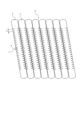
- It is a side view which shows the modification of the reinforcement body shown in FIG.
- It is a side view which shows the modification of the groove part shown in FIG.
- It is a side view which shows the modification of the groove part shown in FIG.
- FIG. is a side view which shows the modification of the groove part shown in FIG.
- FIG. is a side view which shows the modification of the groove part shown in FIG.
- FIG. 1 is a side view of a catheter according to one embodiment
- FIG. FIG. 2 is a partial cross-sectional side view taken along line AA of FIG. 1
- FIG. 3 is a cross-sectional view taken along line BB of FIG. 2
- It is a side view which shows the modification of the reinforcement body shown in FIG.
- a catheter 1 includes an elongate tubular catheter body wall 2 centered on an axis O and at least one element provided within the catheter body wall 2. , wherein at least one strand 3 has at least one groove 4 .
- Catheter 1 may be an imaging catheter, a guiding catheter, a microcatheter, or the like.
- the catheter 1 has a catheter body wall 2, a hub 5, a first wire portion 6a, a second wire portion 6b and a groove portion 7.
- the hub 5 continues to the proximal end of the catheter body wall 2 .
- the end positioned forward when the catheter 1 is introduced into the body cavity is referred to as the distal end, and the opposite end is referred to as the proximal end.
- the hub 5 has a tubular shape centered on the axis O, and the lumen of the hub 5 communicates with the lumen of the catheter body wall 2 .
- the catheter body wall 2 has an inner layer 2a and an outer layer 2b.
- the inner layer 2a and the outer layer 2b each have a long tubular shape centered on the axis O, and the outer layer 2b is provided radially outside the inner layer 2a.
- the inner layer 2a and the outer layer 2b are each made of a synthetic resin material. Materials for forming the inner layer 2a and the outer layer 2b can be appropriately set according to the use of the catheter 1 and the like.
- the first wire portion 6a and the second wire portion 6b are provided between the inner layer 2a and the outer layer 2b, respectively.
- the first wire portion 6a and the second wire portion 6b are each embedded in the outer layer 2b radially outside the inner layer 2a.
- the first wire portion 6a is formed of two wires 3 and is a double spiral coil body centered on the axis O. That is, the first wire portion 6a is provided inside the catheter body wall 2 over the entire circumference.
- the first strand portion 6a forms a contrast marker. That is, the first wire portion 6a is made of a material such as Pt, Au, or the like, which has low X-ray transparency.
- the cross-sectional shape (the shape in the cross section perpendicular to the axial direction) of each wire 3 itself forming the first wire portion 6a is circular.
- the first wire portion 6a is provided only at the distal end portion 1a of the catheter 1 .
- the first wire portion 6a is provided closer to the distal end than the second wire portion 6b.
- the second wire portion 6b is formed of one wire 3 and is a single-helical coil body centered on the axis O. That is, the second wire portion 6b is provided inside the catheter body wall 2 over the entire circumference.
- the second wire portion 6b forms a reinforcement. That is, the second wire portion 6b is made of a highly rigid material such as metal.
- the cross-sectional shape of the wire 3 itself forming the second wire portion 6b is circular.
- the second wire portion 6b is provided over the entire portion of the catheter main body wall 2 excluding the distal end portion.
- each wire 3 itself forming the first wire portion 6a has a double spiral groove 4 formed by two grooves 4. Therefore, the first wire portion 6a has a groove portion 7 formed by four grooves 4. As shown in FIG. Each groove 4 extends spirally along the axial direction (longitudinal direction) of the wire 3 itself. Each groove 4 has two side surfaces 4a facing each other and a bottom surface 4b connecting the side surfaces 4a. The material forming the outer layer 2b enters into each groove 4, thereby realizing strong bonding strength between the outer layer 2b and the first strand portion 6a.
- Each groove 4 has a constant width W (the distance between the side surfaces 4a) and a constant depth D (the depth D of the bottom surface 4b).
- the groove portion 7 forms a predetermined pattern in which a portion of the groove 4 is arranged at a predetermined pitch P in the width direction of the groove 4 .
- the pitch P of the groove portions 7 is constant.
- Each groove 4 is provided over the entire axial length of the wire 3 itself. Therefore, the groove portion 7 is provided on the entire circumference around the axis O in the first wire portion 6a.
- each groove 4 is not particularly limited.
- the outer peripheral surface of the wire 3 itself is irradiated with a laser or the like that is irradiated perpendicularly to the axial direction while rotating the wire 3 itself in a state of being linearly extended before being formed into a coil and feeding it in the axial direction while rotating it in the circumferential direction.
- Each groove 4 can be formed by cutting the .
- each strand 3 itself forming the second strand portion 6 b does not have the groove 4 . That is, the groove 4 is provided only in the first wire portion 6a. Therefore, the groove 4 is provided only at the distal end portion 1a of the catheter 1. As shown in FIG.
- the groove portion 7 flexibility can be enhanced while ensuring X-ray contrastability of the first wire portion 6a.
- the width W, depth D, and pitch P of the groove 4 of the groove portion 7 the flexibility of the distal end portion 1a of the catheter 1 can be easily set.
- the first wire portion 6a may be a helical coil body other than a double helical coil body. It can be a body.
- the cross-sectional shape of each wire 3 itself forming the first wire portion 6a may be other than circular, and may be oval, rectangular, square, polygonal, or the like.
- the second wire portion 6b may be a helical coil body other than a single helical coil body. It can be a body.
- the cross-sectional shape of each wire 3 itself forming the second wire portion 6b may be other than circular, and may be oval, rectangular, square, polygonal, or the like.
- the second wire portion 6b may not be a coil body, but may be a braided body formed by weaving a plurality of wire strands 3 into a tubular shape.
- the second wire portion 6b may be a net tubular braided body as a reinforcing body also called a braid.
- each strand 3 itself forming the braid has a circular cross-sectional shape.
- the cross-sectional shape of each strand 3 itself forming the braided body may be other than circular, and may be oval, rectangular, square, polygonal, or the like.
- the first wire portion 6a may not be provided on the distal end side of the second wire portion 6b. section may be provided.
- each wire 3 forming the first wire portion 6a may have a spiral groove 4 other than a double spiral, for example, a single spiral groove 4. Alternatively, it may have three or more multiple spiral grooves 4 .
- Each groove 4 forming the groove portion 7 may be provided annularly instead of spirally.
- the outer peripheral surface of each wire 3 itself forming the first wire portion 6a has a plurality of annular grooves arranged at a predetermined pitch P in the axial direction of the wire 3 itself. 4. Only one groove 4 is labeled in FIG.
- the groove portion 7 may be provided not only in the first wire portion 6a but also in the second wire portion 6b.
- each groove 4 forming the groove portion 7 of the second wire portion 6b may be spirally or annularly provided.
- a configuration may be adopted in which the first wire portion 6a having the groove portion 7 is provided and the second wire portion 6b is not provided.
- a configuration may be adopted in which the second wire portion 6b having the groove portion 7 is provided without providing the first wire portion 6a.
- a configuration in which not each strand 3 forming the first strand portion 6a but only a part of the strand 3 has at least one groove 4 may be employed.
- a configuration in which not each wire 3 forming the second wire portion 6b but only a portion of the wire 3 has at least one groove 4 is also possible.
- each groove 4 forming the groove portion 7 provided in the wire portion 6 may be provided in a shape other than spiral or annular.
- each groove 4 forming the groove portion 7 provided in the wire portion 6 may extend along the axial direction of the catheter body wall 2 (direction along the axis O). good.
- each groove 4 may be provided only in a portion of the wire portion 6 located radially outside of the catheter body wall 2 (radially outside of the axis O). Only one groove 4 is labeled in FIG.
- At least one groove 4 is formed by irradiating the wire portion 6 (at least one wire 3) with a laser beam while the wire portion 6 (at least one wire 3) is provided inside the catheter body wall 2.
- the groove portion 7 can be easily formed by the forming irradiation process.
- the wavelength of the laser light used in the irradiation step is set to a wavelength at which the wire portion 6 made of metal or the like easily absorbs heat and the catheter main body wall 2 made of synthetic resin or the like hardly absorbs heat.
- the irradiation step may be performed after the wire portion 6 is provided on the outer surface of the inner layer 2a of the catheter body wall 2 and before the outer layer 2b is provided.
- Each groove 4 forming the groove portion 7 provided in the wire portion 6 may extend in the axial direction of the catheter body wall 2 or may extend in other directions.
- Each groove 4 forming a groove portion 7 provided in the wire portion 6 is located in the catheter body in the wire portion 6 in addition to or instead of the portion of the wire portion 6 located radially outside the catheter body wall 2 . It may be provided in a portion located radially inward of the wall 2 .
- the groove portions 7 provided in the wire portions 6 may be provided on both or one side in the axial direction of the catheter body wall 2 in at least one wire portion 3 itself.
- the configuration may be such that they are arranged in two directions (perpendicular to the paper surface of FIG. 7 or 8). Only one groove 4 is labeled in FIG. 7 or 8 . According to such a configuration, flexibility in a specific direction can be enhanced while ensuring the pushability of the strand portion 6 .
- the groove portions 7 provided in the portions of the wire portions 6 aligned in the second direction are provided only on both sides of the catheter body wall 2 in the axial direction of at least one wire portion 3 itself, as in the modification shown in FIG. 7, for example. good too.
- the groove portion 7 provided in the portion of the wire portion 6 aligned in the second direction may be provided only on one surface of the catheter main body wall 2 in the axial direction of at least one wire portion 3 itself. According to such a configuration, flexibility in the first direction can be enhanced while ensuring the pushability of the wire portion 6 .
- the groove portions 7 provided in the portions of the wire portions 6 that are aligned in the second direction may be provided only on both surfaces in the second direction of at least one wire portion 3 itself, or only on one surface, as in the modification shown in FIG. good. According to such a configuration, flexibility in the second direction can be enhanced while ensuring the pushability of the wire portion 6 .
- the groove portion 7 provided in the wire portion 6 is not limited to a configuration in which the width W, depth D and pitch P of the groove 4 are constant.
- the groove portion 7 provided in the wire portion 6 may have a configuration in which the pitch P of the groove 4 decreases from the proximal side to the distal side of the catheter 1, or the width W or depth of the groove 4 may be D may be configured to increase from the proximal side of the catheter 1 toward the distal side. According to such a configuration, it is possible to efficiently improve the flexibility of the distal end portion 1a of the catheter 1 while ensuring the pushability of the wire portion 6 .
- catheter 1 according to the embodiment described above can be modified in various ways, for example, as described below.
- the catheter 1 according to the embodiment described above has an elongated tubular catheter body wall 2 and at least one strand 3 provided in the catheter body wall 2, and the at least one strand 3 is connected to at least one As long as the catheter 1 has the groove 4, various modifications are possible.
- the catheter 1 is not limited to the configuration having the hub 5.
- the structure of the catheter body wall 2 is not limited to having the inner layer 2a and the outer layer 2b.
- the first wire portion 6a is not limited to the coil body.
- the first wire portion 6a is not limited to the contrast marker.
- the second wire portion 6b may have a form other than the coiled body and the braided body.
- the second wire portion 6b is not limited to the reinforcing body.
- the catheter 1 is preferably a catheter 1 in which at least one groove 4 is provided only in the distal end portion 1a of the catheter 1.
- the catheter 1 according to the embodiment described above is preferably a catheter 1 in which at least one groove 4 has a pitch P that decreases from the proximal end side to the distal end side of the catheter 1 .
- the catheter 1 according to the above-described embodiment is preferably a catheter 1 in which the width W or depth D of at least one groove 4 increases from the proximal side to the distal side of the catheter 1 .
- the catheter 1 according to the embodiment described above is preferably a catheter 1 in which at least one strand 3 forms a contrast marker or reinforcement.
- the catheter 1 according to the above-described embodiment is preferably a catheter 1 in which at least one strand 3 is provided inside the catheter body wall 2 over the entire circumference.
- the catheter 1 according to the embodiment described above is preferably a catheter 1 in which at least one strand 3 forms a coiled body or a braided body.
- the catheter 1 according to the above-described embodiment is preferably a catheter 1 in which at least one groove 4 is provided in at least one wire 3 along the entire circumference of the catheter body wall 2 .
- the at least one groove 4 is not provided in the portion of the at least one element wire 3 that is aligned in the first direction perpendicular to the axial direction of the catheter body wall 2, and at least one element It is also preferred that the catheter 1 is provided at a portion of the catheter body wall 2 at the line 3 which is aligned in a second direction perpendicular to both the axial direction and the first direction.
- the catheter 1 is preferably a catheter 1 in which at least one groove 4 is provided only on both sides in the second direction or only on one side of at least one strand 3 itself.
- the catheter 1 is also preferably a catheter 1 in which at least one groove 4 is provided on only one or both axial sides of the catheter body wall 2 at the at least one strand 3 itself.
- the catheter 1 according to the embodiment described above is preferably a catheter 1 in which at least one groove 4 extends in the axial direction of the catheter body wall 2 .
- the catheter 1 is preferably a catheter 1 in which at least one groove 4 is provided only in a portion of at least one strand 3 located radially outside the catheter body wall 2 .
- the catheter 1 according to the above-described embodiment is also preferably a catheter 1 in which at least one groove 4 is spirally or annularly provided on the outer peripheral surface of at least one strand 3 itself.
- At least one wire 3 is provided in the catheter body wall 2, and at least one wire 3 is irradiated with a laser beam to form at least one groove 4. It is preferable that the method for manufacturing the catheter 1 has an irradiation step of forming a .
Landscapes
- Health & Medical Sciences (AREA)
- Life Sciences & Earth Sciences (AREA)
- Biophysics (AREA)
- Pulmonology (AREA)
- Engineering & Computer Science (AREA)
- Anesthesiology (AREA)
- Biomedical Technology (AREA)
- Heart & Thoracic Surgery (AREA)
- Hematology (AREA)
- Animal Behavior & Ethology (AREA)
- General Health & Medical Sciences (AREA)
- Public Health (AREA)
- Veterinary Medicine (AREA)
- Media Introduction/Drainage Providing Device (AREA)
Priority Applications (3)
| Application Number | Priority Date | Filing Date | Title |
|---|---|---|---|
| JP2023543992A JPWO2023027161A1 (https=) | 2021-08-26 | 2022-08-25 | |
| CN202280057767.0A CN117858736A (zh) | 2021-08-26 | 2022-08-25 | 导管 |
| US18/421,358 US20240157088A1 (en) | 2021-08-26 | 2024-01-24 | Catheter |
Applications Claiming Priority (2)
| Application Number | Priority Date | Filing Date | Title |
|---|---|---|---|
| JP2021-138213 | 2021-08-26 | ||
| JP2021138213 | 2021-08-26 |
Related Child Applications (1)
| Application Number | Title | Priority Date | Filing Date |
|---|---|---|---|
| US18/421,358 Continuation US20240157088A1 (en) | 2021-08-26 | 2024-01-24 | Catheter |
Publications (1)
| Publication Number | Publication Date |
|---|---|
| WO2023027161A1 true WO2023027161A1 (ja) | 2023-03-02 |
Family
ID=85322952
Family Applications (1)
| Application Number | Title | Priority Date | Filing Date |
|---|---|---|---|
| PCT/JP2022/032115 Ceased WO2023027161A1 (ja) | 2021-08-26 | 2022-08-25 | カテーテル |
Country Status (4)
| Country | Link |
|---|---|
| US (1) | US20240157088A1 (https=) |
| JP (1) | JPWO2023027161A1 (https=) |
| CN (1) | CN117858736A (https=) |
| WO (1) | WO2023027161A1 (https=) |
Citations (4)
| Publication number | Priority date | Publication date | Assignee | Title |
|---|---|---|---|---|
| JPH11155956A (ja) * | 1997-12-01 | 1999-06-15 | Asahi Intecc Co Ltd | カテーテル |
| JP2013158588A (ja) * | 2012-02-08 | 2013-08-19 | Sumitomo Bakelite Co Ltd | 医療用コイル、医療機器および医療用コイルの製造方法 |
| JP2013192692A (ja) * | 2012-03-19 | 2013-09-30 | Sumitomo Bakelite Co Ltd | 医療用コイル、医療機器および医療用コイルの製造方法 |
| JP2022047161A (ja) * | 2020-09-11 | 2022-03-24 | 朝日インテック株式会社 | カテーテル |
-
2022
- 2022-08-25 JP JP2023543992A patent/JPWO2023027161A1/ja active Pending
- 2022-08-25 WO PCT/JP2022/032115 patent/WO2023027161A1/ja not_active Ceased
- 2022-08-25 CN CN202280057767.0A patent/CN117858736A/zh active Pending
-
2024
- 2024-01-24 US US18/421,358 patent/US20240157088A1/en active Pending
Patent Citations (4)
| Publication number | Priority date | Publication date | Assignee | Title |
|---|---|---|---|---|
| JPH11155956A (ja) * | 1997-12-01 | 1999-06-15 | Asahi Intecc Co Ltd | カテーテル |
| JP2013158588A (ja) * | 2012-02-08 | 2013-08-19 | Sumitomo Bakelite Co Ltd | 医療用コイル、医療機器および医療用コイルの製造方法 |
| JP2013192692A (ja) * | 2012-03-19 | 2013-09-30 | Sumitomo Bakelite Co Ltd | 医療用コイル、医療機器および医療用コイルの製造方法 |
| JP2022047161A (ja) * | 2020-09-11 | 2022-03-24 | 朝日インテック株式会社 | カテーテル |
Also Published As
| Publication number | Publication date |
|---|---|
| US20240157088A1 (en) | 2024-05-16 |
| CN117858736A (zh) | 2024-04-09 |
| JPWO2023027161A1 (https=) | 2023-03-02 |
Similar Documents
| Publication | Publication Date | Title |
|---|---|---|
| JP5757532B2 (ja) | カテーテル | |
| JP2005525133A (ja) | 血管内カテーテルのための一体化されたポリマーおよび編組体 | |
| JPWO2006085498A1 (ja) | 医療用カテーテルチューブならびにその製造方法 | |
| JP5649131B2 (ja) | 医療用チューブ及びこれを用いたカテーテル | |
| JP7647987B2 (ja) | カテーテル | |
| JP6089876B2 (ja) | 医療機器 | |
| JP2023535468A5 (https=) | ||
| US11484687B2 (en) | Catheter | |
| WO2016035740A1 (ja) | カテーテル | |
| WO2023027161A1 (ja) | カテーテル | |
| JP6195382B2 (ja) | 医療用チューブ体 | |
| JP6205785B2 (ja) | 医療機器 | |
| JPWO2020255736A5 (https=) | ||
| WO2020031409A1 (ja) | ガイドワイヤ | |
| JP7748835B2 (ja) | ガイドワイヤ | |
| JP6209841B2 (ja) | 医療用機器 | |
| JP6201368B2 (ja) | 医療用機器 | |
| JP5957966B2 (ja) | 医療機器及び医療機器の製造方法 | |
| JPWO2023027161A5 (https=) | ||
| JP2013192717A (ja) | 医療機器 | |
| JP2017189213A (ja) | 補強部材、及び、カテーテル | |
| WO2019146086A1 (ja) | カテーテル | |
| JP6162802B2 (ja) | カテーテル | |
| JP7298162B2 (ja) | 医療用機器 | |
| JP7165268B2 (ja) | 医療器具 |
Legal Events
| Date | Code | Title | Description |
|---|---|---|---|
| 121 | Ep: the epo has been informed by wipo that ep was designated in this application |
Ref document number: 22861449 Country of ref document: EP Kind code of ref document: A1 |
|
| ENP | Entry into the national phase |
Ref document number: 2023543992 Country of ref document: JP Kind code of ref document: A |
|
| WWE | Wipo information: entry into national phase |
Ref document number: 202280057767.0 Country of ref document: CN |
|
| NENP | Non-entry into the national phase |
Ref country code: DE |
|
| 122 | Ep: pct application non-entry in european phase |
Ref document number: 22861449 Country of ref document: EP Kind code of ref document: A1 |