WO2023026773A1 - 焼入れ装置及び焼入れ方法並びに金属板の製造方法 - Google Patents
焼入れ装置及び焼入れ方法並びに金属板の製造方法 Download PDFInfo
- Publication number
- WO2023026773A1 WO2023026773A1 PCT/JP2022/029364 JP2022029364W WO2023026773A1 WO 2023026773 A1 WO2023026773 A1 WO 2023026773A1 JP 2022029364 W JP2022029364 W JP 2022029364W WO 2023026773 A1 WO2023026773 A1 WO 2023026773A1
- Authority
- WO
- WIPO (PCT)
- Prior art keywords
- metal plate
- cooling
- roll
- quenching
- temperature
- Prior art date
- Legal status (The legal status is an assumption and is not a legal conclusion. Google has not performed a legal analysis and makes no representation as to the accuracy of the status listed.)
- Ceased
Links
Images




Classifications
-
- C—CHEMISTRY; METALLURGY
- C21—METALLURGY OF IRON
- C21D—MODIFYING THE PHYSICAL STRUCTURE OF FERROUS METALS; GENERAL DEVICES FOR HEAT TREATMENT OF FERROUS OR NON-FERROUS METALS OR ALLOYS; MAKING METAL MALLEABLE, e.g. BY DECARBURISATION OR TEMPERING
- C21D9/00—Heat treatment, e.g. annealing, hardening, quenching or tempering, adapted for particular articles; Furnaces therefor
- C21D9/0062—Heat-treating apparatus with a cooling or quenching zone
-
- C—CHEMISTRY; METALLURGY
- C21—METALLURGY OF IRON
- C21D—MODIFYING THE PHYSICAL STRUCTURE OF FERROUS METALS; GENERAL DEVICES FOR HEAT TREATMENT OF FERROUS OR NON-FERROUS METALS OR ALLOYS; MAKING METAL MALLEABLE, e.g. BY DECARBURISATION OR TEMPERING
- C21D9/00—Heat treatment, e.g. annealing, hardening, quenching or tempering, adapted for particular articles; Furnaces therefor
- C21D9/52—Heat treatment, e.g. annealing, hardening, quenching or tempering, adapted for particular articles; Furnaces therefor for wires; for strips ; for rods of unlimited length
- C21D9/54—Furnaces for treating strips or wire
- C21D9/56—Continuous furnaces for strip or wire
- C21D9/573—Continuous furnaces for strip or wire with cooling
-
- B—PERFORMING OPERATIONS; TRANSPORTING
- B21—MECHANICAL METAL-WORKING WITHOUT ESSENTIALLY REMOVING MATERIAL; PUNCHING METAL
- B21B—ROLLING OF METAL
- B21B45/00—Devices for surface or other treatment of work, specially combined with or arranged in, or specially adapted for use in connection with, metal-rolling mills
- B21B45/02—Devices for surface or other treatment of work, specially combined with or arranged in, or specially adapted for use in connection with, metal-rolling mills for lubricating, cooling, or cleaning
-
- C—CHEMISTRY; METALLURGY
- C21—METALLURGY OF IRON
- C21D—MODIFYING THE PHYSICAL STRUCTURE OF FERROUS METALS; GENERAL DEVICES FOR HEAT TREATMENT OF FERROUS OR NON-FERROUS METALS OR ALLOYS; MAKING METAL MALLEABLE, e.g. BY DECARBURISATION OR TEMPERING
- C21D1/00—General methods or devices for heat treatment, e.g. annealing, hardening, quenching or tempering
- C21D1/18—Hardening; Quenching with or without subsequent tempering
-
- C—CHEMISTRY; METALLURGY
- C21—METALLURGY OF IRON
- C21D—MODIFYING THE PHYSICAL STRUCTURE OF FERROUS METALS; GENERAL DEVICES FOR HEAT TREATMENT OF FERROUS OR NON-FERROUS METALS OR ALLOYS; MAKING METAL MALLEABLE, e.g. BY DECARBURISATION OR TEMPERING
- C21D1/00—General methods or devices for heat treatment, e.g. annealing, hardening, quenching or tempering
- C21D1/56—General methods or devices for heat treatment, e.g. annealing, hardening, quenching or tempering characterised by the quenching agents
- C21D1/60—Aqueous agents
-
- C—CHEMISTRY; METALLURGY
- C21—METALLURGY OF IRON
- C21D—MODIFYING THE PHYSICAL STRUCTURE OF FERROUS METALS; GENERAL DEVICES FOR HEAT TREATMENT OF FERROUS OR NON-FERROUS METALS OR ALLOYS; MAKING METAL MALLEABLE, e.g. BY DECARBURISATION OR TEMPERING
- C21D1/00—General methods or devices for heat treatment, e.g. annealing, hardening, quenching or tempering
- C21D1/62—Quenching devices
- C21D1/63—Quenching devices for bath quenching
-
- C—CHEMISTRY; METALLURGY
- C21—METALLURGY OF IRON
- C21D—MODIFYING THE PHYSICAL STRUCTURE OF FERROUS METALS; GENERAL DEVICES FOR HEAT TREATMENT OF FERROUS OR NON-FERROUS METALS OR ALLOYS; MAKING METAL MALLEABLE, e.g. BY DECARBURISATION OR TEMPERING
- C21D1/00—General methods or devices for heat treatment, e.g. annealing, hardening, quenching or tempering
- C21D1/62—Quenching devices
- C21D1/667—Quenching devices for spray quenching
-
- C—CHEMISTRY; METALLURGY
- C21—METALLURGY OF IRON
- C21D—MODIFYING THE PHYSICAL STRUCTURE OF FERROUS METALS; GENERAL DEVICES FOR HEAT TREATMENT OF FERROUS OR NON-FERROUS METALS OR ALLOYS; MAKING METAL MALLEABLE, e.g. BY DECARBURISATION OR TEMPERING
- C21D11/00—Process control or regulation for heat treatments
- C21D11/005—Process control or regulation for heat treatments for cooling
-
- C—CHEMISTRY; METALLURGY
- C21—METALLURGY OF IRON
- C21D—MODIFYING THE PHYSICAL STRUCTURE OF FERROUS METALS; GENERAL DEVICES FOR HEAT TREATMENT OF FERROUS OR NON-FERROUS METALS OR ALLOYS; MAKING METAL MALLEABLE, e.g. BY DECARBURISATION OR TEMPERING
- C21D6/00—Heat treatment of ferrous alloys
- C21D6/005—Heat treatment of ferrous alloys containing Mn
-
- C—CHEMISTRY; METALLURGY
- C21—METALLURGY OF IRON
- C21D—MODIFYING THE PHYSICAL STRUCTURE OF FERROUS METALS; GENERAL DEVICES FOR HEAT TREATMENT OF FERROUS OR NON-FERROUS METALS OR ALLOYS; MAKING METAL MALLEABLE, e.g. BY DECARBURISATION OR TEMPERING
- C21D6/00—Heat treatment of ferrous alloys
- C21D6/008—Heat treatment of ferrous alloys containing Si
-
- C—CHEMISTRY; METALLURGY
- C21—METALLURGY OF IRON
- C21D—MODIFYING THE PHYSICAL STRUCTURE OF FERROUS METALS; GENERAL DEVICES FOR HEAT TREATMENT OF FERROUS OR NON-FERROUS METALS OR ALLOYS; MAKING METAL MALLEABLE, e.g. BY DECARBURISATION OR TEMPERING
- C21D8/00—Modifying the physical properties of ferrous metals or ferrous alloys by deformation combined with, or followed by, heat treatment
- C21D8/02—Modifying the physical properties of ferrous metals or ferrous alloys by deformation combined with, or followed by, heat treatment during manufacturing of plates or strips
- C21D8/0221—Modifying the physical properties of ferrous metals or ferrous alloys by deformation combined with, or followed by, heat treatment during manufacturing of plates or strips characterised by the working steps
- C21D8/0242—Flattening; Dressing; Flexing
-
- C—CHEMISTRY; METALLURGY
- C21—METALLURGY OF IRON
- C21D—MODIFYING THE PHYSICAL STRUCTURE OF FERROUS METALS; GENERAL DEVICES FOR HEAT TREATMENT OF FERROUS OR NON-FERROUS METALS OR ALLOYS; MAKING METAL MALLEABLE, e.g. BY DECARBURISATION OR TEMPERING
- C21D9/00—Heat treatment, e.g. annealing, hardening, quenching or tempering, adapted for particular articles; Furnaces therefor
- C21D9/46—Heat treatment, e.g. annealing, hardening, quenching or tempering, adapted for particular articles; Furnaces therefor for sheet metals
-
- C—CHEMISTRY; METALLURGY
- C21—METALLURGY OF IRON
- C21D—MODIFYING THE PHYSICAL STRUCTURE OF FERROUS METALS; GENERAL DEVICES FOR HEAT TREATMENT OF FERROUS OR NON-FERROUS METALS OR ALLOYS; MAKING METAL MALLEABLE, e.g. BY DECARBURISATION OR TEMPERING
- C21D9/00—Heat treatment, e.g. annealing, hardening, quenching or tempering, adapted for particular articles; Furnaces therefor
- C21D9/52—Heat treatment, e.g. annealing, hardening, quenching or tempering, adapted for particular articles; Furnaces therefor for wires; for strips ; for rods of unlimited length
- C21D9/54—Furnaces for treating strips or wire
- C21D9/56—Continuous furnaces for strip or wire
- C21D9/573—Continuous furnaces for strip or wire with cooling
- C21D9/5735—Details
- C21D9/5737—Rolls; Drums; Roll arrangements
-
- C—CHEMISTRY; METALLURGY
- C22—METALLURGY; FERROUS OR NON-FERROUS ALLOYS; TREATMENT OF ALLOYS OR NON-FERROUS METALS
- C22C—ALLOYS
- C22C38/00—Ferrous alloys, e.g. steel alloys
-
- C—CHEMISTRY; METALLURGY
- C21—METALLURGY OF IRON
- C21D—MODIFYING THE PHYSICAL STRUCTURE OF FERROUS METALS; GENERAL DEVICES FOR HEAT TREATMENT OF FERROUS OR NON-FERROUS METALS OR ALLOYS; MAKING METAL MALLEABLE, e.g. BY DECARBURISATION OR TEMPERING
- C21D2211/00—Microstructure comprising significant phases
- C21D2211/008—Martensite
-
- C—CHEMISTRY; METALLURGY
- C22—METALLURGY; FERROUS OR NON-FERROUS ALLOYS; TREATMENT OF ALLOYS OR NON-FERROUS METALS
- C22C—ALLOYS
- C22C38/00—Ferrous alloys, e.g. steel alloys
- C22C38/002—Ferrous alloys, e.g. steel alloys containing In, Mg, or other elements not provided for in one single group C22C38/001 - C22C38/60
-
- C—CHEMISTRY; METALLURGY
- C22—METALLURGY; FERROUS OR NON-FERROUS ALLOYS; TREATMENT OF ALLOYS OR NON-FERROUS METALS
- C22C—ALLOYS
- C22C38/00—Ferrous alloys, e.g. steel alloys
- C22C38/02—Ferrous alloys, e.g. steel alloys containing silicon
-
- C—CHEMISTRY; METALLURGY
- C22—METALLURGY; FERROUS OR NON-FERROUS ALLOYS; TREATMENT OF ALLOYS OR NON-FERROUS METALS
- C22C—ALLOYS
- C22C38/00—Ferrous alloys, e.g. steel alloys
- C22C38/04—Ferrous alloys, e.g. steel alloys containing manganese
-
- C—CHEMISTRY; METALLURGY
- C22—METALLURGY; FERROUS OR NON-FERROUS ALLOYS; TREATMENT OF ALLOYS OR NON-FERROUS METALS
- C22C—ALLOYS
- C22C38/00—Ferrous alloys, e.g. steel alloys
- C22C38/12—Ferrous alloys, e.g. steel alloys containing tungsten, tantalum, molybdenum, vanadium, or niobium
-
- C—CHEMISTRY; METALLURGY
- C22—METALLURGY; FERROUS OR NON-FERROUS ALLOYS; TREATMENT OF ALLOYS OR NON-FERROUS METALS
- C22C—ALLOYS
- C22C38/00—Ferrous alloys, e.g. steel alloys
- C22C38/14—Ferrous alloys, e.g. steel alloys containing titanium or zirconium
-
- C—CHEMISTRY; METALLURGY
- C22—METALLURGY; FERROUS OR NON-FERROUS ALLOYS; TREATMENT OF ALLOYS OR NON-FERROUS METALS
- C22C—ALLOYS
- C22C38/00—Ferrous alloys, e.g. steel alloys
- C22C38/16—Ferrous alloys, e.g. steel alloys containing copper
-
- C—CHEMISTRY; METALLURGY
- C22—METALLURGY; FERROUS OR NON-FERROUS ALLOYS; TREATMENT OF ALLOYS OR NON-FERROUS METALS
- C22C—ALLOYS
- C22C38/00—Ferrous alloys, e.g. steel alloys
- C22C38/18—Ferrous alloys, e.g. steel alloys containing chromium
- C22C38/32—Ferrous alloys, e.g. steel alloys containing chromium with boron
-
- C—CHEMISTRY; METALLURGY
- C22—METALLURGY; FERROUS OR NON-FERROUS ALLOYS; TREATMENT OF ALLOYS OR NON-FERROUS METALS
- C22C—ALLOYS
- C22C38/00—Ferrous alloys, e.g. steel alloys
- C22C38/18—Ferrous alloys, e.g. steel alloys containing chromium
- C22C38/38—Ferrous alloys, e.g. steel alloys containing chromium with more than 1.5% by weight of manganese
-
- C—CHEMISTRY; METALLURGY
- C22—METALLURGY; FERROUS OR NON-FERROUS ALLOYS; TREATMENT OF ALLOYS OR NON-FERROUS METALS
- C22C—ALLOYS
- C22C38/00—Ferrous alloys, e.g. steel alloys
- C22C38/60—Ferrous alloys, e.g. steel alloys containing lead, selenium, tellurium, or antimony, or more than 0.04% by weight of sulfur
Definitions
- the present invention relates to a quenching apparatus, a quenching method, and a method of manufacturing a metal plate that perform annealing while continuously conveying the metal plate.
- a water quenching method is known as one of the techniques with the fastest cooling rate for a metal plate. In the water quenching method, a heated metal plate is immersed in water and at the same time cooling water is sprayed onto the metal plate from a quench nozzle provided in the water, thereby quenching the metal plate.
- Patent Documents 1 and 2 various methods have been proposed to prevent shape defects of metal plates during quenching (see Patent Documents 1 and 2, for example).
- Patent Document 1 when the temperature at the Ms point where the martensitic transformation of the metal plate starts is TMs (°C) and the temperature at the Mf point where the martensitic transformation ends is TMf (°C), the temperature of the metal plate is (
- a method has been proposed in which a metal plate is constrained by a pair of constraining rolls provided in a cooling liquid in the range of TMs+150) (°C) to (TMf-150) (°C).
- Patent Document 2 when performing a quenching method in which water is jetted from a plurality of water jet nozzles onto the surface of a metal plate to cool it, the metal plate is restrained by restraint rolls, and the metal plate is cooled by a cooling fluid using a movable mask. It is disclosed to control the distance between the cooling start position and the constraining roll.
- the present invention has been made to solve such problems, by controlling the temperature of the metal plate at the position where the metal plate is restrained with high accuracy, and suppressing the variation in the shape of the metal plate that occurs during quenching. It is an object of the present invention to provide a quenching apparatus and a quenching method, and a method for manufacturing a metal plate product.
- a metal plate quenching apparatus that cools a metal plate while it is being conveyed, comprising: a cooling device that cools the metal plate that is being conveyed; a restraint roll, a roll moving device for moving the restraint roll along the conveying direction of the metal plate, and a movement control device for controlling the operation of the roll movement device to adjust the position of the restraint roll. Quenching equipment for metal plates.
- a cooling device that cools the metal plate that is being conveyed
- a restraint roll a roll moving device for moving the restraint roll along the conveying direction of the metal plate
- a movement control device for controlling the operation of the roll movement device to adjust the position of the restraint roll. Quenching equipment for metal plates.
- the cooling device has a plurality of nozzles for cooling the metal plate by injecting a cooling fluid.
- the cooling device has a cooling tank in which the metal plate is immersed and cooled.
- the movement control device controls the operation of the roll movement device, and positions the constraining roll so that the constraining roll constrains the metal plate at a position where the metal plate reaches a target temperature.
- a target temperature is (TMs + 150), where TMs (°C) is the temperature at the Ms point where the martensitic transformation of the metal plate starts, and TMf (°C) is the temperature at the Mf point where the martensitic transformation ends. (° C.) to (TMf-150) (° C.).
- the movement control device determines the distance from the cooling start position by the cooling device to the restraint roll, the conveying speed of the metal plate, the cooling start temperature of the metal plate when the cooling is started by the cooling device, The apparatus for hardening a metal plate according to [4] or [5], wherein the position of the constraining roll is set based on the target temperature and the cooling rate of the metal plate, and the position of the constraining roll is moved to the set distance.
- the movement control device controls the transport speed of the metal plate to be v (mm/s), the cooling start temperature to T1 (°C), the target temperature to T2 (°C), and the cooling device to cool the metal plate.
- the target temperature is (TMs + 150) where TMs (°C) is the temperature at the Ms point where the martensitic transformation of the metal plate starts, and TMf (°C) is the temperature at the Mf point where the martensitic transformation ends. (° C.) to (TMf-150) (° C.).
- the movement of the constraining roll is performed at the cooling start position based on the conveying speed of the metal plate, the cooling start temperature of the metal plate at the start of cooling, the target temperature, and the cooling speed of the metal plate. to the constraining roll, and moving the constraining roll to the set distance.
- the distance from the cooling start position to the constraining roll is v (mm/s) as the conveying speed of the metal plate, T1 (°C) as the cooling start temperature, T2 (°C) as the target temperature, and T2 (°C) as the target temperature.
- a method for producing a high-strength steel sheet wherein the high-strength steel sheet obtained by the method described in [14] is subjected to any one of hot-dip galvanizing treatment, electro-galvanizing treatment, or galvannealing treatment.
- the position of the constraining roll is adjusted along the conveying direction of the metal plate according to the temperature of the metal plate, thereby controlling the distance from the cooling start position to the constraining roll. , it is possible to suppress the variation in the shape of the metal plate that occurs during quenching.
- FIG. 9 is a graph showing the relationship between the conveying speed and the target temperature in Comparative Example 2.
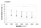
- FIG. 9 is a graph showing the relationship between the conveying speed and the amount of warpage of the metal plate in Comparative Example 2.
- FIG. It is a figure explaining a constraining roll and movement of a nozzle in other examples of a quenching device concerning an embodiment of the present invention.
- FIG. 1 is a schematic diagram showing a hardening apparatus according to an embodiment of the present invention.
- the quenching apparatus 1 shown in FIG. 1 is for quenching a steel material, for example, as a metal sheet S, and is applied to a cooling facility provided on the delivery side of a soaking zone of a continuous annealing furnace.
- a hardening apparatus 1 for a metal plate S shown in FIG. 1 includes a cooling device 10 that cools the metal plate S, and restraint rolls 20 that restrain the cooled metal plate S in the thickness direction.
- the cooling device 10 cools the metal plate S using the cooling fluid CF. and a plurality of nozzles 12 for jetting. Water is stored in the cooling tank 11 as a cooling fluid CF, and for example, the metal plate S is immersed from the upper surface of the cooling tank 11 in the conveying direction BD. A sink roll 2 for changing the conveying direction of the metal plate S is installed in the cooling tank 11 .
- the plurality of nozzles 12 are, for example, quench nozzles or the like, and are installed on both sides of the metal plate S along the conveying direction of the metal plate S. Therefore, the metal plate S is cooled by the cooling fluid CF in the cooling tank 11 and the cooling fluid CF jetted from the plurality of nozzles 12 .
- the cooling fluid CF in the cooling tank 11 By cooling the metal plate S using both the cooling bath 11 and the plurality of nozzles 12 in this manner, the boiling state of the surface of the metal plate S can be stabilized, and uniform shape control can be performed.
- FIG. 1 illustrates a case where a plurality of nozzles 12 are installed in the cooling bath 11, but the cooling method is limited to this as long as it is a method that can cool the metal plate S within a desired temperature range. not.
- the metal plate S may be cooled only by the cooling bath 11 or may be cooled only by the plurality of nozzles 12 .
- the distance between the metal plate S and the nozzle 12 is important in rapid cooling by liquid quenching. It is desirable to install the nozzle 12 close to the metal plate S in order to perform rapid cooling by breaking the vapor film generated by the boiling phenomenon with the liquid jet.
- the distance between the tip of the nozzle 12 and the metal plate S is preferably 10 mm or more and 150 mm or less. If it is less than 10 mm, the deformed and fluttering metal plate S may come into contact with the nozzle 12 . On the other hand, if it exceeds 150 mm, the effect of destroying the vapor film becomes weak, and it may become difficult to ensure sufficient cooling capacity.
- the constraining rolls 20 constrain the metal plate S cooled by the cooling device 10 in the thickness direction, and are installed on both sides of the metal plate S in the cooling tank 11 respectively.
- a pair of restraint rolls 20 are installed so as to face each other, but they may be installed at positions shifted along the conveying direction as long as they restrain.
- FIG. 1 illustrates a case where a pair of restraint rolls 20 is installed, a plurality of pairs of restraint rolls 20 may be installed along the transport direction.
- the roll diameter of the constraining roll 20 is preferably 50 mm or more and 300 mm or less from the correlation between the roll rigidity and the deflection caused by the constraining stress.
- the material of the constraining roll 20 is not limited. When a general steel roll is used as the restraining roll 20 and the roll diameter is less than 50 mm, the roll rigidity is insufficient, and it is difficult to apply a uniform restraining force to the metal plate S due to deflection. and there is a possibility of damage.
- the roll diameter is larger than 300 mm, the section in which the jet from the nozzle 12 does not reach the metal plate S becomes longer, and the steam film may not be sufficiently destroyed, resulting in a decrease in cooling capacity.
- the constraining roll 20 is installed movably along the conveying direction of the metal plate S.
- the conveying direction refers to the direction in which the metal plate S is conveyed.
- the hardening apparatus 1 for the metal plate S includes a roll moving device 30 that moves the constraining rolls 20 and a movement control device 40 that controls the movement of the constraining rolls 20 .
- the roll moving device 30 includes a known driving means such as a motor, and moves the restraint roll 20 along the conveying direction of the metal plate S in the conveying direction BD of the metal plate S or in the direction opposite to the conveying direction BD. configured to move.
- the roll moving device 30 is suitable by combining mechanical parts such as a power jack, a screw type lifting device with a screw mechanism or a gear mechanism, and a linear motion guide (LM guide) that uses rolling and has low resistance.
- FIG. 1 shows an example in which the roll moving device 30 is configured by a screw-type lifting device.
- a restraint roll 20 is rotatably attached to one end of the L-shaped arm 31 .
- a threaded portion 32 , another threaded portion that engages with the threaded portion 32 , and driving means (not shown) for driving the other threaded portion are provided on the other end side of the arm 31 .
- the driving means are fixed to a fixed part (not shown). Therefore, when the torque generated by the driving means rotates the other threaded portion, the arm 31 moves in a direction parallel to the conveying direction BD.
- the drive means described above is immersed in liquid, maintenance of the drive means may become difficult. Therefore, it is preferable that the drive means be installed above the liquid surface of the cooling bath 11 . Moreover, it is preferable that the drive means be installed in a space shielded from the inside of the furnace, which becomes a high temperature.
- the roll moving device 30 may have a function of moving the restraint roll 20 in the thickness direction of the metal plate S to restrain and release the restraint of the metal plate S. Any method can be used as long as it can be moved, but an electric type is more preferable in consideration of responsiveness.
- the movement control device 40 consists of hardware resources such as computers, and controls movement of the restraint roll 20 .
- the movement control device 40 controls the operation of the roll movement device 30 and positions the restraint roll 20 so that the metal plate S is restrained at the position RP where the target temperature is reached.
- the target temperature is defined as (TMs+150)( ° C.) to (TMf-150) (° C.).
- the movement control device 40 calculates the distance d from the cooling start position SP of the metal plate S by the cooling fluid CF to the position RP at which the restraint roll 20 reaches the target temperature, and moves the restraint roll 20 based on the calculated distance d. move. At this time, the movement control device 40 controls the conveying speed v (mm/s) of the metal plate S, the cooling start temperature T1 (°C), the target temperature T2 (°C) to be restrained by the restraining rolls 20, the metal plate S by the cooling device 10 The distance d is calculated using the cooling rate CV (°C/s) of .
- the cooling start temperature T1 is the temperature of the metal plate S immediately before the cooling start position SP where cooling of the metal plate S is started by the cooling fluid CF.
- the temperature immediately before reaching the cooling start position SP can be calculated based on the cooling state of the metal sheet S up to the cooling start position SP and the hardening device 1 .
- the temperature of the metal sheet S is measured with a non-contact type thermometer on the delivery side of the soaking zone of the continuous annealing furnace.
- the temperature of the metal sheet S immediately before or at the time of reaching the cooling start position SP can be calculated based on the temperature and the amount of temperature decrease due to the natural cooling of the metal sheet S until it reaches the quenching device 1. can.
- the amount of temperature decrease due to the natural cooling of the metal plate S described above can be obtained in advance by experiments.
- the above parameters may be obtained sequentially from the set values of the process computer or actual operation values, or may be measured using a speed sensor, temperature sensor, or the like.
- the cooling rate CV (°C/s) is determined by the nozzle shape or the coefficient ⁇ (°C mm/s) indicating the cooling conditions such as the type, temperature, and injection amount of the cooling fluid CF to be jetted, and the thickness of the metal plate S. It can be represented by the following formula (3) using t.
- the distance d can be expressed by the following formula (3).
- the movement control device 40 stores the cooling rate CV (°C/s) or ⁇ (°C ⁇ mm/s) obtained in advance through experiments, numerical analysis, or the like. Then, the movement control device 40 obtains the distance d using the formula (1) or the formula (3), and moves the restraint roll 20 so as to restrain the metal plate S at the position of the obtained distance d.
- the metal plate S is cooled by the cooling device 10 while being conveyed, and the metal plate S is quenched.
- the restraint roll 20 moves along the transport direction so as to restrain the thickness direction of the metal plate S, which is at the target temperature T2 at the position RP.
- the distance d is calculated using the above formula (1) or formula (3), and the restraint roll 20 is moved so as to restrain the metal plate S at the position of the calculated distance d. do.
- the movement of the restraining rolls 20 can be performed sequentially even while the metal plate S is being quenched.
- the movement control device 40 may calculate the distance d and move the restraint roll 20 at the timing when the conveying speed v is changed.
- the transport speed of the metal plate S fluctuates even for one metal plate S (within one coil). Therefore, if the metal plate S can be moved in the conveying direction or in the opposite direction while being restrained by the restraining rolls 20, the yield due to the defective shape of the decelerating portions such as the front end and the tail end of the metal plate S can be improved. preferable.
- the movement control device 40 may calculate the distance d and move the restraint roll 20 every set period.
- the moving distance of the constraining roll 20 for adjusting the constraining roll 20 to the constraining position RP of the metal plate S based on the distance d can be realistically estimated to be approximately 10 mm to 150 mm.
- the restraint roll 20 is moved up and down between the nozzles 12 while the distance between the nozzles 12 is widened in advance to about 10 mm to 150 mm. good.
- the temperature of the constrained metal plate S can be adjusted by about 10° C. to 150° C., and the movement distance of the constraining roll 20 is practically This is a sufficient control adjustment range.
- FIG. 9 is a diagram showing another example of the hardening device according to the embodiment of the present invention.
- a hardening device 50 shown in FIG. 9 includes a nozzle moving device 60 for moving the nozzle 12 in addition to the roll moving device 30 for moving the constraining roll 20 .
- the nozzle moving devices 60 are arranged on both sides of the metal plate S, respectively, as shown in FIG. 9(A).
- the nozzle moving device 60 is configured to move the nozzle 12 along the metal plate S and move the nozzle 12 toward and away from the metal plate S.
- the restraint rolls 20 on both sides of the metal plate S are offset in the vertical direction.
- the nozzle moving device 60 includes an elevating device 62 that moves the cooling pipes 61 communicating with the respective nozzles 12 in the vertical direction of the cooling device 10 , and the elevating device 62 with respect to the metal plate S. and a slider 63 for approaching and separating.
- the lifting device 62 is configured to be able to lift and lower each of the plurality of cooling pipes 61 independently of each other.
- the lifting device 62 and the slider 63 may be conventionally known ones. again.
- a control device (not shown) for controlling the driving of the lifting device 62 and the slider 63 is provided.
- FIG. 9 illustrates the case of moving upward. That is, the restraint roll 20 is moved to the position RP suitable for the target temperature T2 of the metal plate S.
- FIG. 9B shows that state.
- FIG. 9(B) shows that state.
- each nozzle 12 is brought close to the metal plate S by the slider 63, and the distance between them is set to the preset distance and maintained.
- FIG. 9(D) shows that state.
- the distance between the nozzles 12 is widened to about 10 mm to 150 mm in substantially the same manner as the example shown in FIG. , the restraint roll 20 may be moved to adjust to the above position RP. Further, if the cooling capacity permits, the space between the metal plate S and the nozzle 12 may be widened so that the restraint roll 20 can move 150 mm or more.
- the restraint roll 20 is installed movably along the conveying direction, thereby controlling the distance from the cooling start position to the restraint roll 20, and regardless of the manufacturing conditions of the metal plate S, the target The metal plate S at temperature T2 can be constrained by the constraining rolls 20 .
- the constraining rolls 20 As a result, in the continuous annealing equipment, it is possible to suppress shape defects of the metal sheet S due to manufacturing conditions of the metal sheet S that occur during quenching.
- the temperature of the metal plate S conveyed to the hardening apparatus 1 varies depending on the manufacturing conditions of the metal plate, such as the conveying speed v, the cooling start temperature T1 of the metal plate S, and the thickness t of the metal plate S, for example. Therefore, if the distance d is set constant regardless of the manufacturing conditions, the temperature of the metal sheet S when it reaches the restraining rolls 20 also varies.
- the metal plate S is a high-strength steel plate (high-tensile steel)
- the effect of suppressing deformation is particularly large.
- it is preferably applied to the production of steel sheets having a tensile strength of 580 MPa or more.
- the upper limit of the tensile strength is not particularly limited, it may be 2000 MPa or less as an example.
- the high-strength steel sheets (high-tensile steel) include high-strength cold-rolled steel sheets, hot-dip galvanized steel sheets, electro-galvanized steel sheets, alloyed hot-dip galvanized steel sheets, and the like.
- the composition of the high-strength steel sheet in mass%, C is 0.04% or more and 0.35% or less, Si is 0.01% or more and 2.50% or less, and Mn is 0.80% or more and 3 .70% or less, P is 0.001% or more and 0.090% or less, S is 0.0001% or more and 0.0050% or less, sol.
- Al is 0.005% or more and 0.065% or less, if necessary, at least one of Cr, Mo, Nb, V, Ni, Cu, and Ti is 0.5% or less, and if necessary , B, and Sb are each 0.01% or less, and the balance is Fe and unavoidable impurities.
- the metal plate S is not limited to a steel plate, and may be a metal plate other than a steel plate.
- a high-strength cold-rolled steel sheet having a thickness t of 1.0 mm and a width of 1000 mm and a tensile strength of 1470 MPa was quenched using the quenching apparatus 1 according to the embodiment of the present invention.
- the composition of the high-strength cold-rolled steel sheet with a tensile strength of 1470 MPa is 0.20% C, 1.0% Si, 2.3% Mn, 0.005% P, and 0 S in mass%. .002%.
- the temperature TMs at the Ms point of the high-strength cold-rolled steel sheet is 300°C, and the temperature TMf at the Mf point is 250°C.
- the target temperature T2 when passing through the restraining rolls 20 may be set in the range of 450.degree. C. to 100.degree.
- the cooling start temperature T1 was set at 800°C
- the target temperature T2 was set at 400°C.
- the temperature of the cooling fluid CF was set at 30° C.
- the cooling rate CV was set at 1500 (° C./s).
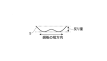
- FIG. 2 is a schematic diagram showing an example of the definition of the amount of warpage. As shown in FIG. 2, the amount of warpage was defined as the height from the contact surface to the highest point when the steel plate was placed on a horizontal surface.
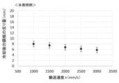
- FIG. 3 is a graph showing the relationship between the conveying speed v and the target temperature in the example of the present invention, and FIG. be.
- the temperature (° C.) when the constraining rolls 20 pass can be kept to the target value by moving the constraining rolls 20 according to the conveying speed v and changing the distance d. Everything could be controlled at a temperature of 400 ⁇ 25°C.
- the amount of warpage of all the steel sheets was reduced to 10 mm or less.
- the variation in the amount of warpage that is, the difference between the maximum value and the minimum value was suppressed to 4.2 mm.
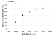
- FIG. 5 is a graph showing the relationship between the conveying speed v and the target temperature in Comparative Example 1
- FIG. 6 is a graph showing the relationship between the conveying speed v and the warp amount of the steel plate as the metal plate S in Comparative Example 1.
- Comparative Example 1 a quenching apparatus in which a constraining roll 20 was fixed as in Patent Document 1 was used, and other conditions were the same as those of the above-described example of the present invention.
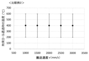
- FIG. 7 is a graph showing the relationship between the conveying speed v and the target temperature in Comparative Example 2
- FIG. 8 is a graph showing the relationship between the conveying speed v and the warp amount of the steel plate as the metal plate S in Comparative Example 2.
- the target temperature T2 is (TMs+150) (° C.) to (TMf ⁇ 150) (° C.), but is not limited to this.
- the target temperature T2 is set to (TMs + 150) (°C) ⁇ ( It may not be limited to TMf-150) (°C).
- the target temperature T2 is determined in advance in consideration of the expected shape (for example, the amount of warpage) while keeping in mind the degree of freedom of processing and operation in the post-process.
- the position adjustment controls the distance d from the cooling start position to the restraint rolls 20 .
- the temperature of the metal plate S when passing through the restraining rolls 20 is set to a predetermined temperature T2, and the shape (for example, the amount of warp) of the metal plate S is approximately the same, for example, the amount of warp defined in FIG.
- the variation should be within 4 mm.
- the number of the restraint rolls 20 is not limited to one pair, and may be provided in a plurality of pairs or a plurality of rolls. In that case, the position of the entire constraining roll pair may be controlled collectively, or a mechanism for controlling the position and opening/closing of each of a plurality of constraining rolls may be employed.
Landscapes
- Chemical & Material Sciences (AREA)
- Engineering & Computer Science (AREA)
- Mechanical Engineering (AREA)
- Materials Engineering (AREA)
- Metallurgy (AREA)
- Organic Chemistry (AREA)
- Physics & Mathematics (AREA)
- Thermal Sciences (AREA)
- Crystallography & Structural Chemistry (AREA)
- Heat Treatment Of Strip Materials And Filament Materials (AREA)
- Control Of Heat Treatment Processes (AREA)
Priority Applications (6)
| Application Number | Priority Date | Filing Date | Title |
|---|---|---|---|
| KR1020247004915A KR20240035542A (ko) | 2021-08-24 | 2022-07-29 | ??칭 장치 및 ??칭 방법 그리고 금속판의 제조 방법 |
| US18/682,680 US20240360530A1 (en) | 2021-08-24 | 2022-07-29 | Quenching apparatus, quenching method, and method of manufacturing metal sheet |
| CN202280055945.6A CN117813405A (zh) | 2021-08-24 | 2022-07-29 | 淬火装置及淬火方法以及金属板的制造方法 |
| JP2022559513A JP7464143B2 (ja) | 2021-08-24 | 2022-07-29 | 焼入れ装置及び焼入れ方法並びに金属板の製造方法 |
| MX2024002107A MX2024002107A (es) | 2021-08-24 | 2022-07-29 | Aparato de temple rapido, metodo de temple rapido y metodo de fabricacion de laminas de metal. |
| EP22861064.8A EP4372105A4 (en) | 2021-08-24 | 2022-07-29 | Quenching device, quenching method, and metal sheet manufacturing method |
Applications Claiming Priority (2)
| Application Number | Priority Date | Filing Date | Title |
|---|---|---|---|
| JP2021136141 | 2021-08-24 | ||
| JP2021-136141 | 2021-08-24 |
Publications (1)
| Publication Number | Publication Date |
|---|---|
| WO2023026773A1 true WO2023026773A1 (ja) | 2023-03-02 |
Family
ID=85323012
Family Applications (1)
| Application Number | Title | Priority Date | Filing Date |
|---|---|---|---|
| PCT/JP2022/029364 Ceased WO2023026773A1 (ja) | 2021-08-24 | 2022-07-29 | 焼入れ装置及び焼入れ方法並びに金属板の製造方法 |
Country Status (7)
| Country | Link |
|---|---|
| US (1) | US20240360530A1 (https=) |
| EP (1) | EP4372105A4 (https=) |
| JP (1) | JP7464143B2 (https=) |
| KR (1) | KR20240035542A (https=) |
| CN (1) | CN117813405A (https=) |
| MX (1) | MX2024002107A (https=) |
| WO (1) | WO2023026773A1 (https=) |
Citations (4)
| Publication number | Priority date | Publication date | Assignee | Title |
|---|---|---|---|---|
| JPH04114549U (ja) * | 1991-03-18 | 1992-10-08 | 中外炉工業株式会社 | 非鉄ストリツプ用竪型連続熱処理炉 |
| JP2011184773A (ja) * | 2010-03-10 | 2011-09-22 | Kobe Steel Ltd | 連続焼鈍設備およびその設備における急冷焼入時の金属板の波状変形抑制方法 |
| WO2016084283A1 (ja) * | 2014-11-28 | 2016-06-02 | Jfeスチール株式会社 | 金属板の製造方法および急冷焼入れ装置 |
| JP2019090106A (ja) | 2017-11-15 | 2019-06-13 | Jfeスチール株式会社 | 急冷焼入れ装置及び急冷焼入れ方法並びに金属板製品の製造方法 |
Family Cites Families (7)
| Publication number | Priority date | Publication date | Assignee | Title |
|---|---|---|---|---|
| JPS462733B1 (https=) * | 1967-02-07 | 1971-01-23 | ||
| JPS598447B2 (ja) * | 1977-10-12 | 1984-02-24 | 三菱重工業株式会社 | 熱間圧延設備の薄板冷却設備 |
| JPS6094722U (ja) | 1983-12-02 | 1985-06-28 | 日立電線株式会社 | アンダ−カ−ペツトケ−ブル |
| CN202945290U (zh) * | 2012-12-10 | 2013-05-22 | 株式会社天田 | 带锯条材料连续淬火冷却装置 |
| JP5928412B2 (ja) * | 2013-06-19 | 2016-06-01 | Jfeスチール株式会社 | 鋼板の竪型冷却装置、およびそれを用いた溶融亜鉛めっき鋼板の製造方法 |
| EP3061535B1 (de) * | 2015-02-27 | 2019-02-27 | Primetals Technologies Austria GmbH | Haspeleinrichtung mit asymmetrischer kühlung des gehaspelten bandes |
| JP6879429B2 (ja) * | 2018-10-25 | 2021-06-02 | Jfeスチール株式会社 | 焼入れ装置及び焼入れ方法並びに鋼板の製造方法 |
-
2022
- 2022-07-29 KR KR1020247004915A patent/KR20240035542A/ko active Pending
- 2022-07-29 EP EP22861064.8A patent/EP4372105A4/en active Pending
- 2022-07-29 US US18/682,680 patent/US20240360530A1/en active Pending
- 2022-07-29 WO PCT/JP2022/029364 patent/WO2023026773A1/ja not_active Ceased
- 2022-07-29 MX MX2024002107A patent/MX2024002107A/es unknown
- 2022-07-29 CN CN202280055945.6A patent/CN117813405A/zh active Pending
- 2022-07-29 JP JP2022559513A patent/JP7464143B2/ja active Active
Patent Citations (5)
| Publication number | Priority date | Publication date | Assignee | Title |
|---|---|---|---|---|
| JPH04114549U (ja) * | 1991-03-18 | 1992-10-08 | 中外炉工業株式会社 | 非鉄ストリツプ用竪型連続熱処理炉 |
| JP2011184773A (ja) * | 2010-03-10 | 2011-09-22 | Kobe Steel Ltd | 連続焼鈍設備およびその設備における急冷焼入時の金属板の波状変形抑制方法 |
| WO2016084283A1 (ja) * | 2014-11-28 | 2016-06-02 | Jfeスチール株式会社 | 金属板の製造方法および急冷焼入れ装置 |
| JP6094722B2 (ja) | 2014-11-28 | 2017-03-15 | Jfeスチール株式会社 | 金属板の製造方法および急冷焼入れ装置 |
| JP2019090106A (ja) | 2017-11-15 | 2019-06-13 | Jfeスチール株式会社 | 急冷焼入れ装置及び急冷焼入れ方法並びに金属板製品の製造方法 |
Also Published As
| Publication number | Publication date |
|---|---|
| JPWO2023026773A1 (https=) | 2023-03-02 |
| MX2024002107A (es) | 2024-03-06 |
| CN117813405A (zh) | 2024-04-02 |
| US20240360530A1 (en) | 2024-10-31 |
| JP7464143B2 (ja) | 2024-04-09 |
| KR20240035542A (ko) | 2024-03-15 |
| EP4372105A4 (en) | 2024-12-25 |
| EP4372105A1 (en) | 2024-05-22 |
Similar Documents
| Publication | Publication Date | Title |
|---|---|---|
| JP6094722B2 (ja) | 金属板の製造方法および急冷焼入れ装置 | |
| JP6687084B2 (ja) | 急冷焼入れ装置及び急冷焼入れ方法並びに金属板製品の製造方法 | |
| JP6870701B2 (ja) | 鋼板の冷却方法、鋼板の冷却装置および鋼板の製造方法 | |
| KR20240096738A (ko) | 퀀칭 장치 및 금속판의 제조 방법 | |
| JP7464143B2 (ja) | 焼入れ装置及び焼入れ方法並びに金属板の製造方法 | |
| JP6879428B2 (ja) | 焼入れ装置及び焼入れ方法並びに鋼板の製造方法 | |
| JP6687090B2 (ja) | 急冷焼入れ装置及び急冷焼入れ方法並びに金属板製品の製造方法 | |
| JP7508024B2 (ja) | 焼入れ装置及び焼入れ方法並びに金属板の製造方法 | |
| US12365956B2 (en) | Metal-strip rapid cooling apparatus, metal-strip rapid cooling method, and method of producing metal strip product | |
| JP7306590B1 (ja) | 焼入れ装置及び連続焼鈍設備、並びに焼入れ方法、鋼板の製造方法及びめっき鋼板の製造方法 | |
| JP7355251B2 (ja) | 金属板の焼入装置、連続焼鈍設備、金属板の焼入方法、冷延鋼板の製造方法及びめっき鋼板の製造方法 | |
| WO2023042795A1 (ja) | 焼入れ装置及び連続焼鈍設備、並びに焼入れ方法、鋼板の製造方法及びめっき鋼板の製造方法 | |
| JP2025175422A (ja) | 焼入れ装置及び金属帯の製造方法 | |
| US20240318272A1 (en) | Quenching apparatus, method for quenching, method for manufacturing cold rolled steel sheet, and method for manufacturing coated steel sheet | |
| TH2401000903A (th) | เครื่องสำหรับการเคว้นช์ วิธีการสำหรับการเคว้นช์และวิธีการผลิตแผ่นโลหะ | |
| JP4389435B2 (ja) | 溶融めっき金属帯の製造方法および製造装置 | |
| TH2401000908A (th) | เครื่องสำหรับการเคว้นช์ วิธีการสำหรับการเคว้นช์และวิธีการผลิตแผ่นโลหะ | |
| JPWO2023026773A5 (https=) |
Legal Events
| Date | Code | Title | Description |
|---|---|---|---|
| ENP | Entry into the national phase |
Ref document number: 2022559513 Country of ref document: JP Kind code of ref document: A |
|
| 121 | Ep: the epo has been informed by wipo that ep was designated in this application |
Ref document number: 22861064 Country of ref document: EP Kind code of ref document: A1 |
|
| WWE | Wipo information: entry into national phase |
Ref document number: 202417001899 Country of ref document: IN |
|
| WWE | Wipo information: entry into national phase |
Ref document number: 202280055945.6 Country of ref document: CN |
|
| WWE | Wipo information: entry into national phase |
Ref document number: 2022861064 Country of ref document: EP |
|
| ENP | Entry into the national phase |
Ref document number: 20247004915 Country of ref document: KR Kind code of ref document: A |
|
| WWE | Wipo information: entry into national phase |
Ref document number: 1020247004915 Country of ref document: KR Ref document number: 2401000903 Country of ref document: TH |
|
| ENP | Entry into the national phase |
Ref document number: 2022861064 Country of ref document: EP Effective date: 20240212 |
|
| NENP | Non-entry into the national phase |
Ref country code: DE |