WO2023021920A1 - 圧電フィルムおよび積層圧電素子 - Google Patents
圧電フィルムおよび積層圧電素子 Download PDFInfo
- Publication number
- WO2023021920A1 WO2023021920A1 PCT/JP2022/028362 JP2022028362W WO2023021920A1 WO 2023021920 A1 WO2023021920 A1 WO 2023021920A1 JP 2022028362 W JP2022028362 W JP 2022028362W WO 2023021920 A1 WO2023021920 A1 WO 2023021920A1
- Authority
- WO
- WIPO (PCT)
- Prior art keywords
- piezoelectric
- layer
- piezoelectric film
- film
- electrode layer
- Prior art date
- Legal status (The legal status is an assumption and is not a legal conclusion. Google has not performed a legal analysis and makes no representation as to the accuracy of the status listed.)
- Ceased
Links
Images




Classifications
-
- H—ELECTRICITY
- H04—ELECTRIC COMMUNICATION TECHNIQUE
- H04R—LOUDSPEAKERS, MICROPHONES, GRAMOPHONE PICK-UPS OR LIKE ACOUSTIC ELECTROMECHANICAL TRANSDUCERS; ELECTRIC HEARING AIDS; PUBLIC ADDRESS SYSTEMS
- H04R17/00—Piezoelectric transducers; Electrostrictive transducers
Definitions
- the present invention relates to a piezoelectric film used for an electroacoustic conversion film, etc., and a laminated piezoelectric element obtained by laminating this piezoelectric film.
- a flexible piezoelectric film has been proposed as a speaker that can be integrated into a flexible display without impairing its lightness and flexibility.
- a piezoelectric layer (polymer composite piezoelectric body) formed by dispersing piezoelectric particles in a viscoelastic matrix made of a polymer material having viscoelasticity at room temperature, and a piezoelectric layer provided on both sides of the piezoelectric layer describes a piezoelectric film (electroacoustic conversion film) having an electrode layer (thin film electrode) coated with a thin film and a protective layer provided on the surface of the electrode layer.
- the piezoelectric layer described in Patent Document 1 has excellent piezoelectric properties. Moreover, since this piezoelectric layer is made by dispersing piezoelectric particles such as lead zirconate titanate particles in a polymer material such as cyanoethylated polyvinyl alcohol, it has good flexibility. Therefore, according to the piezoelectric film using this piezoelectric layer, for example, an electroacoustic transducer that can be used as a piezoelectric speaker or the like, which has flexibility and good piezoelectric characteristics that can be used for a flexible speaker or the like. Films, etc. can be obtained.
- the piezoelectric layer (piezoelectric film) expands and contracts due to the action of the piezoelectric particles.
- the electrode and the piezoelectric layer are in close contact with each other over the entire surface without air bubbles or voids between the electrode and the piezoelectric layer. If there is a gap or the like between the electrode and the piezoelectric layer, a loss occurs when transmitting the vibration of the piezoelectric layer. As a result, for example, in audio output, problems such as a decrease in sound pressure occur.
- the present invention has the following configurations.
- a piezoelectric film in which electrode layers are provided on both sides of a piezoelectric layer containing piezoelectric particles in a matrix containing a polymer material, high sound pressure can be obtained, for example, when used as a piezoelectric speaker.
- FIG. 1 is a conceptual diagram of an example of the piezoelectric film of the present invention.
- FIG. 2 is a conceptual diagram for explaining nanoindentation measurement.
- FIG. 3 is a conceptual diagram for explaining an example of a method for producing a piezoelectric film.
- FIG. 4 is a conceptual diagram for explaining an example of a method for producing a piezoelectric film.
- FIG. 5 is a conceptual diagram for explaining an example of a method for producing a piezoelectric film.
- FIG. 6 is a conceptual diagram for explaining an example of a method for producing a piezoelectric film.
- FIG. 7 is a conceptual diagram for explaining an example of a method for producing a piezoelectric film.
- FIG. 1 is a conceptual diagram of an example of the piezoelectric film of the present invention.
- FIG. 2 is a conceptual diagram for explaining nanoindentation measurement.
- FIG. 3 is a conceptual diagram for explaining an example of a method for producing a piezoelectric film.
- FIG. 8 is a conceptual diagram for explaining an example of a method for producing a piezoelectric film.
- FIG. 9 is a conceptual diagram of an example of a piezoelectric speaker using the piezoelectric film shown in FIG.
- FIG. 10 is a conceptual diagram for explaining the sound pressure measuring method in the example.
- FIG. 1 conceptually shows an example of the piezoelectric film of the present invention.
- the piezoelectric film 10 includes a piezoelectric layer 12 , a first electrode layer 14 laminated on one surface of the piezoelectric layer 12 , and a first electrode layer 14 laminated on the surface of the first electrode layer 14 . It has a protective layer 18 , a second electrode layer 16 laminated on the other surface of the piezoelectric layer 12 , and a second protective layer 20 laminated on the surface of the second electrode layer 16 .
- the piezoelectric layer 12 contains piezoelectric particles 26 in a matrix 24 containing a polymeric material, as conceptually shown in FIG.
- the piezoelectric layer 12 has a maximum indentation amount (maximum indentation depth) d max by nanoindentation measurement that satisfies “100 nm ⁇ d max ⁇ 600 nm”.
- the piezoelectric film 10 of the present invention exists between the first electrode layer 14 and the piezoelectric layer 12 and/or between the second electrode layer 16 and the piezoelectric layer 12. It is possible to greatly reduce air bubbles, voids, and the like. This point will be described in detail later.
- the first and second in the first electrode layer 14 and the second electrode layer 16 and in the first protective layer 18 and the second protective layer 20 refer to two similar members that the piezoelectric film 10 has. are attached for convenience in order to distinguish between That is, the first and second marks attached to the constituent elements of the piezoelectric film 10 have no technical significance, and their positions may be reversed. may be the second protective layer.
- the piezoelectric layer 12 is formed by dispersing the piezoelectric particles 26 in the matrix 24 containing the polymeric material. That is, the piezoelectric layer 12 is a polymer composite piezoelectric.
- the polymer composite piezoelectric body (piezoelectric layer 12) preferably satisfies the following requirements.
- normal temperature is 0 to 50°C.
- Flexibility For example, when gripping a loosely bent state like a document like a newspaper or magazine for portable use, it is constantly subjected to a relatively slow and large bending deformation of several Hz or less from the outside. become.
- the polymer composite piezoelectric body is required to have appropriate hardness in order to increase the transmission efficiency of vibration energy. Also, if the frequency characteristics of the speaker are smooth, the amount of change in sound quality when the lowest resonance frequency f 0 changes as the curvature changes becomes small. Therefore, the loss tangent of the polymer composite piezoelectric body is required to be moderately large.
- the lowest resonance frequency f 0 of the speaker diaphragm is given by the following equation.
- s is the stiffness of the vibration system and m is the mass.
- the flexible polymer composite piezoelectric material used for the electroacoustic conversion film is required to behave hard against vibrations of 20 Hz to 20 kHz and softly against vibrations of several Hz or less. Also, the loss tangent of the polymer composite piezoelectric body is required to be moderately large with respect to vibrations of all frequencies of 20 kHz or less.
- polymer solids have a viscoelastic relaxation mechanism, and as temperature rises or frequency falls, large-scale molecular motion causes a decrease (relaxation) in storage elastic modulus (Young's modulus) or a maximum loss elastic modulus (absorption). is observed as Among them, the relaxation caused by the micro-Brownian motion of the molecular chains in the amorphous region is called principal dispersion, and a very large relaxation phenomenon is observed.
- the temperature at which this primary dispersion occurs is the glass transition point (Tg), and the viscoelastic relaxation mechanism appears most prominently.
- the polymer composite piezoelectric body (piezoelectric layer 12), by using a polymer material having a glass transition point at room temperature, in other words, a polymer material having viscoelasticity at room temperature as a matrix, it is possible to suppress vibrations of 20 Hz to 20 kHz. This realizes a polymer composite piezoelectric material that is hard at first and behaves softly with respect to slow vibrations of several Hz or less.
- a polymer material having a glass transition point at room temperature ie, 0 to 50° C. at a frequency of 1 Hz, for the matrix of the polymer composite piezoelectric material, because this behavior is favorably expressed.
- the polymer material having viscoelasticity at room temperature can be used as the polymer material having viscoelasticity at room temperature. It is preferable to use a polymeric material having a maximum value of loss tangent Tan ⁇ at a frequency of 1 Hz in a dynamic viscoelasticity test at normal temperature, ie, 0 to 50° C., of 0.5 or more. As a result, when the polymer composite piezoelectric body is slowly bent by an external force, the stress concentration at the interface between the polymer matrix and the piezoelectric particles at the maximum bending moment is relaxed, and high flexibility can be expected.
- the polymer material having viscoelasticity at room temperature preferably has a storage elastic modulus (E') at a frequency of 1 Hz measured by dynamic viscoelasticity of 100 MPa or more at 0°C and 10 MPa or less at 50°C.
- E' storage elastic modulus
- the polymer material having viscoelasticity at room temperature has a dielectric constant of 10 or more at 25°C.
- a voltage is applied to the polymer composite piezoelectric material, a higher electric field is applied to the piezoelectric particles in the polymer matrix, so a large amount of deformation can be expected.
- the polymer material in consideration of ensuring good moisture resistance and the like, it is also suitable for the polymer material to have a dielectric constant of 10 or less at 25°C.
- cyanoethylated polyvinyl alcohol cyanoethylated PVA
- polyvinyl acetate polyvinylidene chloride core acrylonitrile
- polystyrene-vinylpolyisoprene block copolymer examples include methyl ketone and polybutyl methacrylate.
- Commercially available products such as Hybler 5127 (manu
- the polymer material it is preferable to use a material having a cyanoethyl group, and it is particularly preferable to use cyanoethylated PVA.
- the matrix 24 only one type of these polymer materials having viscoelasticity at room temperature may be used, or a plurality of types may be used together (mixed).
- a polymer material having no viscoelasticity at room temperature may be added to the matrix 24, if necessary.
- the matrix 24 contains a polymer material having viscoelasticity at room temperature such as cyanoethylated PVA for the purpose of adjusting dielectric properties and mechanical properties, and if necessary, other dielectric polymer materials. You may add.
- dielectric polymer materials examples include polyvinylidene fluoride, vinylidene fluoride-tetrafluoroethylene copolymer, vinylidene fluoride-trifluoroethylene copolymer, and polyvinylidene fluoride-trifluoroethylene copolymer.
- fluorine-based polymers such as polyvinylidene fluoride-tetrafluoroethylene copolymer, vinylidene cyanide-vinyl acetate copolymer, cyanoethylcellulose, cyanoethylhydroxysaccharose, cyanoethylhydroxycellulose, cyanoethylhydroxypullulan, cyanoethylmethacrylate, cyanoethylacrylate, cyanoethyl Cyano groups such as hydroxyethylcellulose, cyanoethylamylose, cyanoethylhydroxypropylcellulose, cyanoethyldihydroxypropylcellulose, cyanoethylhydroxypropylamylose, cyanoethylpolyacrylamide, cyanoethylpolyacrylate, cyanoethylpullulan, cyanoethylpolyhydroxymethylene, cyanoethylglycidolpullul
- the dielectric polymer material added in addition to the polymer material having viscoelasticity at room temperature such as cyanoethylated PVA is not limited to one type, and a plurality of types may be added. You may
- the matrix 24 may also include thermoplastic resins such as vinyl chloride resin, polyethylene, polystyrene, methacrylic resin, polybutene and isobutylene, and phenolic resin for the purpose of adjusting the glass transition point Tg.
- thermoplastic resins such as vinyl chloride resin, polyethylene, polystyrene, methacrylic resin, polybutene and isobutylene
- phenolic resin for the purpose of adjusting the glass transition point Tg.
- thermosetting resins such as urea resins, melamine resins, alkyd resins and mica
- a tackifier such as rosin ester, rosin, terpene, terpene phenol, and petroleum resin may be added to the matrix 24 for the purpose of improving adhesiveness.
- the addition amount of the material other than the polymer material having viscoelasticity at room temperature such as cyanoethylated PVA is not particularly limited, but the proportion of the matrix 24 is 30 mass. % or less.
- the characteristics of the polymer material to be added can be expressed without impairing the viscoelastic relaxation mechanism in the matrix 24, so that the dielectric constant can be increased, the heat resistance can be improved, and the adhesion between the piezoelectric particles 26 and the electrode layer can be improved.
- favorable results can be obtained in terms of
- the piezoelectric layer 12 contains piezoelectric particles 26 in such a matrix 24 .
- the piezoelectric layer 12 is a polymeric composite piezoelectric body in which piezoelectric particles 26 are dispersed in such a matrix 24 .
- the piezoelectric particles 26 are made of ceramic particles having a perovskite or wurtzite crystal structure.
- Ceramic particles forming the piezoelectric particles 26 include lead zirconate titanate (PZT), lead zirconate lanthanate titanate (PLZT), barium titanate (BaTiO 3 ), zinc oxide (ZnO), and A solid solution (BFBT) of barium titanate and bismuth ferrite (BiFe 3 ) is exemplified. Only one kind of these piezoelectric particles 26 may be used, or a plurality of kinds thereof may be used together (mixed).
- the particle diameter of the piezoelectric particles 26 is not limited, and may be selected as appropriate according to the size and application of the piezoelectric film 10 .
- the particle size of the piezoelectric particles 26 is preferably 1 to 10 ⁇ m. By setting the particle size of the piezoelectric particles 26 within this range, favorable results can be obtained in that the piezoelectric film 10 can achieve both high piezoelectric characteristics and flexibility.
- the piezoelectric particles 26 in the piezoelectric layer 12 are irregularly dispersed in the matrix 24 in FIG. 1, the present invention is not limited to this. That is, the piezoelectric particles 26 in the piezoelectric layer 12 may be dispersed with regularity in the matrix 24 as long as they are preferably uniformly dispersed. Furthermore, the piezoelectric particles 26 may or may not have uniform particle diameters.
- the quantitative ratio of the matrix 24 and the piezoelectric particles 26 in the piezoelectric layer 12 is not limited, and the size and thickness of the piezoelectric film 10 in the plane direction, the application of the piezoelectric film 10, and It may be appropriately set according to the properties required for the piezoelectric film 10 .
- the volume fraction of the piezoelectric particles 26 in the piezoelectric layer 12 is preferably 30% to 80%, more preferably 50% or more, and therefore 50% to 80% is even more preferable.
- the thickness of the piezoelectric layer 12 is not particularly limited, and may be appropriately set according to the application of the piezoelectric film 10, the properties required of the piezoelectric film 10, and the like.
- the thickness of the piezoelectric layer 12 is preferably 8-300 ⁇ m, more preferably 8-200 ⁇ m, still more preferably 10-150 ⁇ m, particularly preferably 15-100 ⁇ m.
- the piezoelectric layer 12, that is, the piezoelectric film 10, is preferably polarized (poled) in the thickness direction.
- the polarization treatment will be detailed later.
- the illustrated piezoelectric film 10 has a first electrode layer 14 on one surface of the piezoelectric layer 12 and a first protective layer 18 on the surface thereof. 12 has a second electrode layer 16 on the other surface thereof, and a second protective layer 20 on the surface thereof.
- the first electrode layer 14 and the second electrode layer 16 form an electrode pair.
- the piezoelectric film 10 has a configuration in which both surfaces of the piezoelectric layer 12 are sandwiched between electrode pairs, and this laminate is sandwiched between the first protective layer 18 and the second protective layer 20 .
- the region sandwiched between the first electrode layer 14 and the second electrode layer 16 expands and contracts according to the applied voltage.
- the first protective layer 18 and the second protective layer 20 cover the first electrode layer 14 and the second electrode layer 16, and provide the piezoelectric layer 12 with appropriate rigidity and mechanical strength. is responsible for That is, in the piezoelectric film 10, the piezoelectric layer 12 made up of the matrix 24 and the piezoelectric particles 26 exhibits excellent flexibility against slow bending deformation, but depending on the application, the rigidity may increase. and mechanical strength may be insufficient.
- the piezoelectric film 10 is preferably provided with a first protective layer 18 and a second protective layer 20 to compensate for this.
- the laminate of the piezoelectric layer 12 and the electrode layer is sandwiched so as to correspond to both the first electrode layer 14 and the second electrode layer 16.
- a first protective layer 18 and a second protective layer 20 are provided.
- the first protective layer 18 and the second protective layer 20 are provided as preferred embodiments. Therefore, the piezoelectric film of the present invention may have neither the first protective layer 18 nor the second protective layer 20 , or may have only one of the first protective layer 18 and the second protective layer 20 . However, in consideration of the mechanical strength, rigidity, durability, etc.
- a laminate of the piezoelectric layer 12 and the electrode layer is sandwiched.
- a first protective layer 18 and a second protective layer 20 are preferably provided on the substrate.
- Various sheet materials can be used for the first protective layer 18 and the second protective layer 20 without limitation, and various resin films are preferably exemplified as examples.
- various resin films are preferably exemplified as examples.
- PET polyethylene terephthalate
- PP polypropylene
- PS polystyrene
- PC polycarbonate
- PPS polyphenylene sulfite
- PMMA polymethyl methacrylate
- PET polyethylene terephthalate
- PEI polyetherimide
- PI polyimide
- PEN polyethylene naphthalate
- TAC triacetyl cellulose
- cyclic olefin resins and the like are preferably used.
- the thicknesses of the first protective layer 18 and the second protective layer 20 are also not limited. Also, the thicknesses of the first protective layer 18 and the second protective layer 20 are basically the same, but may be different. Here, if the rigidity of the first protective layer 18 and the second protective layer 20 is too high, not only will the expansion and contraction of the piezoelectric layer 12 be restricted, but also the flexibility will be impaired. Therefore, the thinner the first protective layer 18 and the second protective layer 20, the better, except for the case where mechanical strength and good handling property as a sheet-like article are required.
- the thickness of the first protective layer 18 and the second protective layer 20 is less than twice the thickness of the piezoelectric layer 12, it is possible to ensure both rigidity and appropriate flexibility. favorable results can be obtained.
- the thickness of the first protective layer 18 and the second protective layer 20 is preferably 100 ⁇ m or less. 50 ⁇ m or less is more preferable, and 25 ⁇ m or less is even more preferable.
- a first electrode layer 14 is formed between the piezoelectric layer 12 and the first protective layer 18 in the piezoelectric film 10 .
- a second electrode layer 16 is formed between the piezoelectric layer 12 and the second protective layer 20 .
- the first electrode layer 14 and the second electrode layer 16 are provided for applying voltage to the piezoelectric layer 12 (piezoelectric film 10).
- the materials for forming the first electrode layer 14 and the second electrode layer 16 are not limited, and various conductors can be used. Specifically, metals such as carbon, palladium, iron, tin, aluminum, nickel, platinum, gold, silver, copper, titanium, chromium and molybdenum, alloys thereof, laminates and composites of these metals and alloys, Also, indium tin oxide and the like are exemplified. Among them, copper, aluminum, gold, silver, platinum, and indium tin oxide are preferably exemplified as the first electrode layer 14 and the second electrode layer 16 .
- the method of forming the first electrode layer 14 and the second electrode layer 16 is not limited, and known methods can be used. Examples include film formation by a vapor phase deposition method (vacuum film formation method) such as vacuum deposition and sputtering, film formation by plating, and a method of adhering a foil formed of the materials described above. Among them, thin films of copper, aluminum, or the like formed by vacuum deposition are particularly preferably used as the first electrode layer 14 and the second electrode layer 16 because the flexibility of the piezoelectric film 10 can be ensured. be. Among them, a copper thin film formed by vacuum deposition is particularly preferably used.
- the thicknesses of the first electrode layer 14 and the second electrode layer 16 are not limited. Also, the thicknesses of the first electrode layer 14 and the second electrode layer 16 are basically the same, but may be different.
- the first protective layer 18 and the second protective layer 20 described above if the rigidity of the first electrode layer 14 and the second electrode layer 16 is too high, not only will the expansion and contraction of the piezoelectric layer 12 be restricted, Flexibility is also impaired. Therefore, the thinner the first electrode layer 14 and the second electrode layer 16, the better, as long as the electrical resistance does not become too high.
- the product of the thickness of the first electrode layer 14 and the second electrode layer 16 and the Young's modulus is less than the product of the thickness of the first protective layer 18 and the second protective layer 20 and the Young's modulus , is preferred because it does not significantly impair flexibility.
- a combination of PET for the first protective layer 18 and the second protective layer 20 and copper for the first electrode layer 14 and the second electrode layer 16 is illustrated.
- PET has a Young's modulus of about 6.2 GPa and copper has a Young's modulus of about 130 GPa.
- the thickness of the first protective layer 18 and the second protective layer 20 is 10 ⁇ m
- the thickness of the first electrode layer 14 and the second electrode layer 16 is preferably 0.5 ⁇ m or less, more preferably 0.3 ⁇ m or less. , is more preferably 0.1 ⁇ m or less.
- a piezoelectric layer may be provided between the piezoelectric layer 12 and the first electrode layer 14 and/or between the piezoelectric layer 12 and the second electrode layer 16, if necessary. It may have an adhesive layer for increasing the adhesion between 12 and the electrode layer.
- the adhesive layer is not limited, and any known adhesive (adhesive, pressure-sensitive adhesive) can be used as long as it can adhere the piezoelectric layer 12 and the electrode layer according to the materials forming the piezoelectric layer 12 and the electrode layer. is.
- the polymer material used as the matrix 24 of the piezoelectric layer 12 may be used as the adhesive layer.
- the thickness of the adhesive layer There is no limitation on the thickness of the adhesive layer, and the thickness may be appropriately set so as to obtain sufficient adhesive strength.
- the adhesive layer is preferably thin as long as the required adhesive strength can be obtained.
- the piezoelectric film 10 of the present invention has the first electrode layer 14 on one side of the piezoelectric layer 12 and the second electrode layer 16 on the other side.
- the illustrated piezoelectric film 10 preferably has a first protective layer 18 covering the first electrode layer 14 and a second protective layer 20 covering the second electrode layer 16 .
- the piezoelectric layer 12 is a polymeric composite piezoelectric body, and is formed by dispersing piezoelectric particles 26 in a matrix 24 containing a polymeric material.
- the piezoelectric layer 12 made of such a polymeric composite piezoelectric material satisfies "100 nm ⁇ d max ⁇ 600 nm" in the maximum indentation amount d max measured by nanoindentation measurement.
- the maximum load holding time is 10 sec
- the unloading time is 10 sec.
- the piezoelectric film 10 of the present invention satisfies "100 nm ⁇ d max ⁇ 600 nm" in the maximum indentation amount d max of the piezoelectric layer 12 in the nanoindentation measurement, that is, the maximum displacement amount. Since the piezoelectric film 10 of the present invention has such a structure, air bubbles and gaps existing between the first electrode layer 14 and the piezoelectric layer 12 or between the second electrode layer 16 and the piezoelectric layer 12 are eliminated. , can be significantly reduced.
- the piezoelectric film 10 having electrode layers on both sides of the piezoelectric layer 12 and having a protective layer covering the electrode layers is manufactured as follows, as an example.
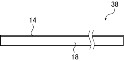
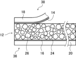
- a sheet 34 in which the second protective layer 20 and the second electrode layer 16 are laminated, and a sheet 38 in which the first protective layer 18 and the first electrode layer 14 are laminated are prepared (FIGS. 4 and 7). reference).
- a coating material is prepared by dissolving a material for the matrix 24 in a solvent and dispersing the piezoelectric particles 26 in this solution. This coating material is applied to the second electrode layer 16 of the sheet material 34 and dried to form the piezoelectric layer 12 (see FIG. 5).
- the piezoelectric multilayer body 36 having the second electrode layer 16 on the second protective layer 20 and the piezoelectric layer 12 on the second electrode layer 16 is produced.
- calendering see FIG. 6
- polarization etc.
- the first electrode layer 14 is directed to the piezoelectric layer 12, and the sheet-like material 38 in which the first protective layer 18 and the first electrode layer 14 are laminated is laminated and heat-pressed.
- the piezoelectric film 10 is produced (see FIG. 8).
- the bonding between the piezoelectric layer 12 and the first electrode layer 14 is performed, for example, by thermocompression bonding using a heating roller pair 60 as conceptually shown in FIG. Specifically, as described above, after manufacturing the piezoelectric multilayer body 36 in which the piezoelectric layer 12 is formed on the second electrode layer 16 of the sheet 34 (see FIG. 5), the first electrode layer 14 is formed. A sheet-like material 38 is laminated on the piezoelectric multilayer body 36 facing the piezoelectric layer 12 (see FIG. 8). The laminate of the piezoelectric multilayer body 36 and the sheet material 38 is nipped and conveyed by the pair of heating rollers 60, so that the piezoelectric layer 12 and the first electrode layer 14 are heat-pressed and adhered. Although this thermocompression bonding is usually performed by pinching and conveying the laminate by the pair of heating rollers 60, conversely, the laminate may be fixed and the pair of heating rollers 60 may be moved.
- a conventional piezoelectric film having a piezoelectric layer 12 made of a polymer composite piezoelectric material air and/or foreign matter F entrained during lamination may cause a problem between the first electrode layer 14 and the piezoelectric layer 12. , air bubbles and/or voids are often unavoidable.
- the piezoelectric layer 12 made of a polymeric composite piezoelectric material satisfies "100 nm ⁇ d max ⁇ 600 nm" in terms of the maximum indentation amount d max measured by nanoindentation. That is, in the piezoelectric film 10 of the present invention, the maximum indentation amount d max of the piezoelectric layer 12 measured by nanoindentation is 100 to 600 nm. In the following description, the maximum pushing amount d max of the piezoelectric layer 12 obtained by nanoindentation measurement is also simply referred to as "the maximum pushing amount d max of the piezoelectric layer 12". Since the piezoelectric film 10 of the present invention has such a structure, as conceptually shown in the lower center of FIG. can be significantly reduced.
- the piezoelectric layer 12 and the first electrode layer 14 are heated by the heating roller pair 60 by setting the maximum pressing amount d max of the piezoelectric layer 12 to 100 to 600 nm.
- the air trapped between the piezoelectric layer 12 and the first electrode layer 14 during lamination can be preferably pushed out.
- the maximum pressing amount d max of the piezoelectric layer 12 is set to 100 to 600 nm, when the piezoelectric layer 12 and the first electrode layer 14 are heat-pressed by the heating roller pair 60, the foreign matter F is removed from the piezoelectric layer. 12 to embed the foreign matter F, preventing air from remaining around the foreign matter F.
- the piezoelectric film 10 of the present invention can greatly reduce the amount of air and voids existing between the piezoelectric layer 12 and the electrode layer, as conceptually shown in the lower center of FIG. Therefore, the piezoelectric film 10 of the present invention can efficiently transmit the vibration of the piezoelectric layer 12, and can output sound with high sound pressure when used as a piezoelectric speaker, for example.
- the maximum push-in amount d max of the piezoelectric layer 12 is less than 100 nm, as conceptually shown on the lower left side of FIG.
- the body layer 12 cannot be fully embedded.
- air bubbles B exist around the foreign matter F between the piezoelectric layer 12 and the first electrode layer 14 .
- the maximum pressing amount d max of the piezoelectric layer 12 exceeds 600 nm, the pressing force during thermocompression bonding between the piezoelectric layer 12 and the first electrode layer 14 becomes insufficient.
- the air trapped between the piezoelectric layer 12 and the first electrode layer 14 during lamination cannot be pushed out, and the gap V (the separation portion) between the piezoelectric layer 12 and the first electrode layer 14 cannot be pushed out.
- the maximum pressing amount d max of the piezoelectric layer 12 is preferably 150 to 550 nm, more preferably 180 to 500 nm.
- the piezoelectric layer 12 is formed by coating the second electrode layer 16 of 34 with a paint that will become the piezoelectric layer 12 and drying it. Therefore, air can be prevented from entering between the second electrode layer 16 and the piezoelectric layer 12 . Also, even if the foreign matter F adheres to the second electrode layer 16 , the foreign matter F is completely embedded in the paint, that is, the piezoelectric layer 12 . The presence of air around the is also avoided.
- the nanoindentation measurement of the piezoelectric layer 12 is performed by removing the protective layer and the electrode layer from the piezoelectric film 10 to expose the piezoelectric layer 12 .
- the surface roughness Ra of the piezoelectric layer 12 and the film thickness distribution of the piezoelectric layer 12, which will be described later, are also preferably measured at the exposed portion of the piezoelectric layer 12 from which the protective layer and the electrode layer are removed.
- the method for removing the protective layer and the electrode layer from the piezoelectric film 10 is not limited, but the following method is exemplified. First, a 5 mol/L (liter) NaOH aqueous solution with a temperature of 15 to 25° C.
- the piezoelectric film 10 is dropped onto the protective layer of the piezoelectric film 10, and left to stand still to dissolve the protective layer and expose the electrode layer. do. At this time, a portion of the electrode layer may be dissolved, but the stationary time is set so that the NaOH aqueous solution does not come into contact with the piezoelectric layer 12 . After dropping the aqueous NaOH solution, the piezoelectric film 10 is left to stand for a predetermined time, and when the electrode layer is exposed, the piezoelectric film 10 is washed with pure water. After washing, the exposed electrode layer is dissolved in a 0.01 mol/L ferric chloride aqueous solution.
- the dissolution of the electrode layer with the ferric chloride aqueous solution is continued until the piezoelectric layer 12 having an area required for nanoindentation measurement is exposed, but not longer than 5 minutes after the piezoelectric layer 12 is exposed.
- the piezoelectric film 10 with the exposed piezoelectric layer 12 is washed with pure water and dried at 30° C. or less.
- the nanoindentation measurement conceptually shown in FIG. Measure the maximum pushing amount d max .
- the maximum push-in amount d max of the piezoelectric layer 12 may be measured on either the first electrode layer 14 side or the second electrode layer 16 side (principal surface) of the piezoelectric layer 12. good.
- the maximum pressing amount d max of the piezoelectric layer 12 is measured at 30 arbitrarily selected points on the surface of the piezoelectric layer 12, and the average value is obtained from the piezoelectric layer 10 in the piezoelectric film 10 to be measured. 12 maximum pushing amount d max .
- the piezoelectric layer 12 preferably has a smooth surface.
- the piezoelectric layer 12 preferably has a surface roughness Ra (arithmetic mean roughness Ra) of 800 nm or less, more preferably 700 nm or less, and even more preferably 600 nm or less.
- Ra arithmetic mean roughness Ra
- the surface roughness Ra (arithmetic mean roughness Ra) of the piezoelectric layer 12 is obtained, for example, by measuring the surface roughness Ra of the surface of the exposed piezoelectric layer using a non-contact three-dimensional surface profile roughness meter manufactured by Bruker. Under the conditions of white LED light source (green filter), objective lens 10x, internal lens 0.55x, CCD: 1280 x 960 pixels, VSI/VXI, observation field of view 825.7 ⁇ m x 619.3 ⁇ m, cross-sectional sampling 0.645 ⁇ m After the measurement, the slope is corrected with 0 as the average, and the measurement is performed by fitting with Gaussian process regression. The surface roughness Ra is measured at 30 arbitrarily selected points, and the average value is taken as the surface roughness Ra of the piezoelectric layer 12 in the piezoelectric film 10 to be measured.
- the piezoelectric layer 12 preferably has a uniform thickness.
- the thickness distribution (film thickness distribution) of the piezoelectric layer 12 is preferably 30% or less, more preferably 25% or less, and even more preferably 20% or less. By setting the thickness distribution of the piezoelectric layer 12 to 30% or less, it is preferable in that high sound pressure can be obtained when used as a piezoelectric speaker.
- the thickness distribution [%] of the piezoelectric layer 12 is obtained by measuring the exposed surface of the piezoelectric layer with a digital indicator (ID-F125 manufactured by Mitutoyo Co., Ltd.). (maximum value ⁇ minimum value)/average of maximum value and minimum value] ⁇ 100”. Such thickness distribution measurements are performed at 30 arbitrarily selected locations, and the average value is used as the thickness distribution of the piezoelectric layer 12 in the piezoelectric film 10 to be measured.
- a digital indicator ID-F125 manufactured by Mitutoyo Co., Ltd.
- the piezoelectric film 10 includes the piezoelectric layer 12 having the piezoelectric particles 26 in the matrix 24 containing a polymer material sandwiched between the first electrode layer 14 and the second electrode layer 16, and furthermore, this laminate is sandwiched between the first protective layer 18 and the second protective layer 20 .
- the maximum value of the loss tangent (Tan ⁇ ) at a frequency of 1 Hz by dynamic viscoelasticity measurement preferably exists at room temperature, and the maximum value of 0.1 or more exists at room temperature. is more preferable.
- the piezoelectric film 10 of the present invention preferably has a storage elastic modulus (E') at a frequency of 1 Hz measured by dynamic viscoelasticity measurement of 10 to 30 GPa at 0°C and 1 to 10 GPa at 50°C. Accordingly, the piezoelectric film 10 can have a large frequency dispersion in the storage elastic modulus (E') at room temperature. That is, it can act hard against vibrations of 20 Hz to 20 kHz and soft against vibrations of several Hz or less.
- E' storage elastic modulus
- the product of the thickness and the storage elastic modulus (E') at a frequency of 1 Hz measured by dynamic viscoelasticity measurement is 1.0 ⁇ 10 6 to 2.0 ⁇ 10 6 at 0° C. It is preferably 1.0 ⁇ 10 5 to 1.0 ⁇ 10 6 N/m at 50° C. N/m.
- the piezoelectric film 10 can have appropriate rigidity and mechanical strength within a range that does not impair flexibility and acoustic properties.
- the piezoelectric film 10 preferably has a loss tangent (Tan ⁇ ) of 0.05 or more at 25° C. and a frequency of 1 kHz in a master curve obtained from dynamic viscoelasticity measurement.
- Ton ⁇ loss tangent
- the frequency characteristics of the speaker using the piezoelectric film 10 are smoothed, and the amount of change in sound quality when the lowest resonance frequency f 0 changes as the curvature of the speaker changes can be reduced.
- the piezoelectric film 10 of the present invention covers the electrode lead-out portions for leading the electrodes from the first electrode layer 14 and the second electrode layer 16 and the area where the piezoelectric layer 12 is exposed.
- it may have an insulating layer or the like for preventing short circuits or the like.
- a method of connecting the conductors and drawing out the electrodes to the outside, and forming through holes in the first protective layer 18 and the second protective layer 20 by a laser or the like, filling the through holes with a conductive material, and , and the like are exemplified.
- suitable methods for extracting electrodes include the method described in Japanese Patent Application Laid-Open No. 2014-209724 and the method described in Japanese Patent Application Laid-Open No. 2016-015354.
- each electrode layer is not limited to one electrode lead-out portion, and may have two or more electrode lead-out portions.
- three or more electrode lead-out portions are provided in order to ensure more reliable conduction of electricity. is preferred.
- a sheet-like object 34 having a second electrode layer 16 formed on a second protective layer 20 is prepared.
- This sheet-like material 34 may be produced by forming a copper thin film or the like as the second electrode layer 16 on the surface of the second protective layer 20 by vacuum deposition, sputtering, plating, or the like.
- the second protective layer 20 with a separator temporary support
- PET or the like having a thickness of 25 to 100 ⁇ m can be used. The separator may be removed after the second electrode layer 16 and the second protective layer 20 are thermally compressed and before laminating any member on the second protective layer 20 .
- a polymer material having viscoelasticity at room temperature such as cyanoethylated PVA
- an organic solvent such as dimethylformamide (DMF), methyl ethyl ketone and cyclohexanone can be used.
- DMF dimethylformamide
- the paint is cast (applied) on the second electrode layer 16 of the sheet 34 and dried by evaporating the organic solvent.
- the thickness distribution of the piezoelectric layer 12 can be adjusted by controlling the coating conditions of the paint at this time.
- the surface roughness of the piezoelectric layer 12 can be adjusted by controlling the drying temperature of the paint at this time.
- the conditions for applying the paint when the application is performed using a slide coater, control of the gap distribution between the slide coater and the backup roller that supports the sheet-like material 34 is exemplified.
- a piezoelectric multilayer body 36 having the second electrode layer 16 on the second protective layer 20 and the piezoelectric layer 12 formed on the second electrode layer 16 is produced. do.
- the method of casting this paint is not particularly limited, and all known coating methods (coating devices) such as slide coaters and doctor knives can be used.
- the viscoelastic material is heat-meltable, such as cyanoethylated PVA
- the viscoelastic material is heated and melted, and the piezoelectric particles 26 are added/dispersed to prepare a melt, which is then extruded.
- the sheet is extruded onto the sheet-like material 34 shown in FIG. 4 and cooled to form the first electrode layer 14 on the first protective layer 18 as shown in FIG.
- a piezoelectric multilayer body 36 may be produced by forming the piezoelectric layer 12 on one electrode layer 14 .
- the matrix 24 may be added with a dielectric polymer material such as polyvinylidene fluoride in addition to the viscoelastic material such as cyanoethylated PVA.
- a dielectric polymer material such as polyvinylidene fluoride
- the polymeric piezoelectric materials to be added to the above-described paint may be dissolved.
- the polymer piezoelectric material to be added may be added to the viscoelastic material melted by heating as described above and melted by heating.
- Calendering is performed by pressing the surface of the piezoelectric layer 12 with a heating roller or the like.
- the method of calendering is not particularly limited, and known methods such as nip-conveyance by a pair of heating rollers, pressing by heating rollers, and treatment by a heating press may be used.
- the maximum pressing amount d max of the piezoelectric layer 12 of the piezoelectric film 10 to be manufactured can be controlled by adjusting the calendering conditions. Specifically, the maximum pressing amount d max of the piezoelectric layer 12 of the piezoelectric film 10 to be manufactured can be suitably You can control it.
- the heating roller pair 62 may be moved while holding the piezoelectric multilayer body 36 at a predetermined position.
- the pushing amount d max can be preferably controlled with good controllability. Specifically, by shortening the nip time, that is, by increasing the conveying speed of the piezoelectric multilayer body 36, the maximum pushing amount d max of the piezoelectric layer 12 can be increased. Conversely, by increasing the nip time, that is, by decreasing the conveying speed of the piezoelectric multilayer body 36, the maximum pressing amount d max of the piezoelectric layer 12 can be reduced.
- the maximum pressing amount d max of the piezoelectric layer 12 can be controlled by various methods other than adjusting the nip time in the calendering process.
- the maximum pushing amount d max of the piezoelectric layer 12 may be controlled by adjusting the composition of the matrix 24 of the piezoelectric layer 12 or the like.
- the calendering treatment may be performed after the polarization treatment described later. However, if the calendering process is performed after the polarization process, the piezoelectric particles 26 pushed in by the pressure will rotate, which may reduce the effect of the polarization process. Considering this point, the calendering treatment is preferably performed before the polarization treatment.
- the piezoelectric layer 12 is preferably calendered. After the treatment, the piezoelectric layer 12 is subjected to polarization treatment (poling).
- the method of polarization treatment of the piezoelectric layer 12 is not limited, and known methods can be used.
- electric field poling in which a DC electric field is directly applied to an object to be polarized, is exemplified.
- the first electrode layer 14 may be formed before the polarization treatment, and the electric field poling treatment may be performed using the first electrode layer 14 and the second electrode layer 16. .
- a sheet-like object 38 having a first electrode layer 14 formed on a first protective layer 18 is prepared.
- This sheet-like material 38 may be produced by forming a copper thin film or the like as the first electrode layer 14 on the surface of the first protective layer 18 by vacuum deposition, sputtering, plating, or the like. That is, the sheet-like material 38 may be the same as the sheet-like material 34 described above.
- the sheet-like material 38 is laminated on the piezoelectric multilayer body 36 with the first electrode layer 14 facing the piezoelectric layer 12 . Furthermore, as shown in FIG. 3, the piezoelectric multilayer body 36 and the sheet-like material 38 are thermo-compressed while being nipped and conveyed by the pair of heating rollers 60 to fabricate the piezoelectric film 10 .
- the piezoelectric film 10 may be produced by thermocompression bonding the laminate of the piezoelectric multilayer body 36 and the sheet-like material 38 using a hot press device.
- the piezoelectric film 10 produced in this manner is polarized in the thickness direction rather than in the plane direction, and excellent piezoelectric properties can be obtained without stretching after the polarization treatment. Therefore, the piezoelectric film 10 has no in-plane anisotropy in piezoelectric properties, and expands and contracts isotropically in all directions in the plane direction when a drive voltage is applied.
- Such a piezoelectric film 10 may be manufactured using a cut-sheet-like sheet-like material 34 and a sheet-like material 38 or the like, or may be manufactured using a roll-to-roll process. good too.
- FIG. 9 conceptually shows an example of a flat plate-type piezoelectric speaker using the piezoelectric film 10 of the present invention.
- This piezoelectric speaker 40 is a flat plate-type piezoelectric speaker that uses the piezoelectric film 10 as a diaphragm that converts an electrical signal into vibrational energy. Note that the piezoelectric speaker 40 can also be used as a microphone, a sensor, and the like. Furthermore, this piezoelectric speaker can also be used as a vibration sensor.
- the piezoelectric speaker 40 includes a piezoelectric film 10 , a case 42 , a viscoelastic support 46 and a frame 48 .
- the case 42 is a thin housing made of plastic or the like and having one side open. Examples of the shape of the housing include rectangular parallelepiped, cubic, and cylindrical.
- the frame 48 is a frame material that engages with the open surface side of the case 42 , having a through hole having the same shape as the open surface of the case 42 in the center.
- the viscoelastic support 46 has appropriate viscosity and elasticity, supports the piezoelectric film 10, and provides a constant mechanical bias at any location on the piezoelectric film, thereby allowing the piezoelectric film 10 to move back and forth without waste.
- Back-and-forth motion of the piezoelectric film 10 is motion in a direction perpendicular to the plane of the film.
- the viscoelastic support 46 include wool felt, non-woven fabric such as wool felt containing PET and the like, glass wool, and the like.
- the piezoelectric speaker 40 accommodates a viscoelastic support 46 in a case 42 , covers the case 42 and the viscoelastic support 46 with the piezoelectric film 10 , and surrounds the piezoelectric film 10 with a frame 48 to form an upper end surface of the case 42 .
- the frame body 48 is fixed to the case 42 in a state of being pressed to.
- the height (thickness) of the viscoelastic support 46 is greater than the height of the inner surface of the case 42 . Therefore, in the piezoelectric speaker 40 , the viscoelastic support 46 is pressed downward by the piezoelectric film 10 and held in a reduced thickness at the periphery of the viscoelastic support 46 . Similarly, the curvature of the piezoelectric film 10 changes sharply at the periphery of the viscoelastic support 46 , forming a rising portion in the piezoelectric film 10 that becomes lower toward the periphery of the viscoelastic support 46 . Further, the central region of the piezoelectric film 10 is pressed by the square prism-shaped viscoelastic support 46 to form a (substantially) planar shape.
- the piezoelectric film 10 when the piezoelectric film 10 expands in the plane direction due to the application of the drive voltage to the first electrode layer 14 and the second electrode layer 16, the action of the viscoelastic support 46 absorbs this expansion. Thus, the rising portion of the piezoelectric film 10 changes its angle in the rising direction. As a result, the piezoelectric film 10 having planar portions moves upward. Conversely, when the piezoelectric film 10 shrinks in the plane direction due to the application of the drive voltage to the second electrode layer 16 and the first electrode layer 14, the rising portion of the piezoelectric film 10 collapses in order to absorb this contraction. Change the angle in the direction (direction closer to the plane). As a result, the piezoelectric film 10 having planar portions moves downward. The piezoelectric speaker 40 generates sound by vibrating the piezoelectric film 10 .
- the piezoelectric film 10 of the present invention conversion from stretching motion to vibration can also be achieved by holding the piezoelectric film 10 in a curved state. Therefore, the piezoelectric film 10 of the present invention is not a flat piezoelectric speaker 40 having rigidity as shown in FIG. can function as
- a piezoelectric speaker using such a piezoelectric film 10 can take advantage of its good flexibility and can be rolled up or folded and accommodated in a bag or the like. Therefore, according to the piezoelectric film 10, it is possible to realize an easily portable piezoelectric speaker even if it has a certain size. Moreover, as described above, the piezoelectric film 10 is excellent in softness and flexibility, and has no in-plane anisotropy of piezoelectric properties. Therefore, the piezoelectric film 10 has little change in sound quality when bent in any direction, and also has little change in sound quality with respect to changes in curvature.
- the piezoelectric speaker using the piezoelectric film 10 has a high degree of freedom in installation location, and can be attached to various articles as described above.
- a so-called wearable speaker can be realized by attaching the piezoelectric film 10 to clothing such as clothes and portable items such as bags in a curved state.
- the piezoelectric film of the present invention by attaching the piezoelectric film of the present invention to a flexible display device such as a flexible organic electroluminescence display and a flexible liquid crystal display, the display device It can also be used as a speaker.
- a flexible display device such as a flexible organic electroluminescence display and a flexible liquid crystal display
- the piezoelectric film 10 expands and contracts in the plane direction when a voltage is applied, and this expansion and contraction in the plane direction suitably vibrates in the thickness direction. It expresses good acoustic characteristics that can output sound.
- the piezoelectric film 10, which exhibits good acoustic properties, that is, high expansion and contraction performance due to piezoelectricity, works well as a piezoelectric vibrating element for vibrating a vibrating body such as a diaphragm by forming a laminated piezoelectric element in which a plurality of sheets are laminated. do.
- the piezoelectric film 10 When the piezoelectric film 10 is laminated, the piezoelectric film may not have the first protective layer 18 and/or the second protective layer 20 if there is no possibility of short circuit. Alternatively, piezoelectric films without the first protective layer 18 and/or the second protective layer 20 may be laminated via an insulating layer.
- a laminated piezoelectric element in which piezoelectric films 10 are laminated may be attached to a diaphragm, and the laminated body of piezoelectric films 10 may vibrate the diaphragm to produce a speaker that outputs sound. That is, in this case, the laminated piezoelectric element in which the piezoelectric film 10 is laminated acts as a so-called exciter that outputs sound by vibrating the diaphragm.
- the individual piezoelectric films 10 expand and contract in the plane direction, and the expansion and contraction of each piezoelectric film 10 causes the entire laminate of the piezoelectric films 10 to expand and contract in the plane direction. do.
- the expansion and contraction of the laminated piezoelectric element in the planar direction bends the diaphragm to which the laminate is attached, and as a result, the diaphragm vibrates in the thickness direction. This vibration in the thickness direction causes the diaphragm to generate sound.
- the diaphragm vibrates according to the magnitude of the driving voltage applied to the piezoelectric film 10 and generates sound according to the driving voltage applied to the piezoelectric film 10 . Therefore, at this time, the piezoelectric film 10 itself does not output sound.
- the laminated piezoelectric element in which the piezoelectric films 10 are laminated has high rigidity, and the expansion/contraction force of the laminate as a whole is large.
- the laminated piezoelectric element in which the piezoelectric film 10 is laminated can sufficiently flex the diaphragm with a large force and sufficiently vibrate the diaphragm in the thickness direction. to make the diaphragm generate sound.
- the number of laminated piezoelectric films 10 is not limited. Just do it. It should be noted that one sheet of piezoelectric film 10 can also be used as a similar exciter (piezoelectric vibrating element) as long as it has sufficient stretching force.
- the vibration plate that is vibrated by the laminated piezoelectric element in which the piezoelectric film 10 is laminated there are no restrictions on the vibration plate that is vibrated by the laminated piezoelectric element in which the piezoelectric film 10 is laminated, and various sheet-like objects (plate-like objects and films) can be used.
- sheet-like objects plate-like objects and films
- resin films such as polyethylene terephthalate (PET)
- foamed plastics such as polystyrene foam
- paper materials such as cardboard, glass plates, and wood.
- various devices such as display devices such as organic electroluminescence displays and liquid crystal displays may be used as the diaphragm as long as they can be bent sufficiently.
- the adjacent piezoelectric films 10 are adhered to each other with an adhesive layer (adhesive).
- both the laminated piezoelectric element and the diaphragm are adhered with an adhesion layer.
- the adhesive layer may be made of a pressure-sensitive adhesive or an adhesive.
- an adhesive layer is used which, after application, results in a solid and hard adhesive layer. The above points are the same for a laminated body formed by folding a long piezoelectric film 10 described later.
- the polarization direction of each laminated piezoelectric film 10 is not limited.
- the piezoelectric film 10 of the present invention is preferably polarized in the thickness direction. Accordingly, the polarization direction of the piezoelectric film 10 referred to herein is the polarization direction in the thickness direction. Therefore, in the laminated piezoelectric element, all the piezoelectric films 10 may have the same polarization direction, or there may be piezoelectric films having different polarization directions.
- the piezoelectric films 10 are preferably laminated so that the polarization directions of the adjacent piezoelectric films 10 are opposite to each other.
- the polarity of the voltage applied to the piezoelectric layer 12 depends on the polarization direction of the piezoelectric layer 12 . Therefore, regardless of whether the polarization direction is from the first electrode layer 14 to the second electrode layer 16 or from the second electrode layer 16 to the first electrode layer 14, the first electrode is The polarity of layer 14 and the polarity of second electrode layer 16 are made the same.
- the laminated piezoelectric element in which the piezoelectric films 10 are laminated may have a configuration in which a plurality of piezoelectric films 10 are laminated by folding the piezoelectric films 10 one or more times, preferably a plurality of times.
- the configuration in which the piezoelectric film 10 is folded and laminated has the following advantages. That is, in a laminate in which a plurality of cut-sheet piezoelectric films 10 are laminated, it is necessary to connect the first electrode layer 14 and the second electrode layer 16 to the drive power source for each piezoelectric film. On the other hand, in the structure in which the long piezoelectric film 10 is folded and laminated, the laminated piezoelectric element can be configured with only one long piezoelectric film 10 .
- the long piezoelectric film 10 is folded and laminated, only one power source is required for applying the driving voltage, and the electrode may be led out from the piezoelectric film 10 at one point. Furthermore, in the structure in which the long piezoelectric films 10 are folded and laminated, the polarization directions of adjacent piezoelectric films 10 are inevitably opposite to each other.
- the laminated piezoelectric element in which electrode layers are provided on both sides of a piezoelectric layer made of a polymer composite piezoelectric body, and preferably a protective layer is provided on the surface of the electrode layer, the laminated piezoelectric element is laminated with a piezoelectric film. 2020/095812 and International Publication No. 2020/179353.
- piezoelectric films and laminated piezoelectric elements of the present invention are used in various applications such as various sensors, acoustic devices, haptics, ultrasonic transducers, actuators, dampers, and vibration power generators. It is preferably used.
- sensors using the piezoelectric film and laminated piezoelectric element of the present invention include sonic sensors, ultrasonic sensors, pressure sensors, tactile sensors, strain sensors, vibration sensors, and the like. Sensors using the piezoelectric film and laminated piezoelectric element of the present invention are particularly useful for inspections at manufacturing sites, such as infrastructure inspections such as crack detection, and foreign matter contamination detection.
- Examples of acoustic devices using the piezoelectric film and laminated piezoelectric element of the present invention include microphones, pickups, speakers, and exciters.
- Specific applications of the acoustic device using the piezoelectric film and laminated piezoelectric element of the present invention include noise cancellers used in cars, trains, airplanes, robots, etc., artificial vocal cords, buzzers for preventing insects from entering, and Examples include furniture, wallpaper, photographs, helmets, goggles, headrests, signage, robots, and the like that have an audio output function.
- Examples of applications of haptics using the piezoelectric film and laminated piezoelectric element of the present invention include automobiles, smart phones, smart watches, and game machines.
- Examples of ultrasonic transducers using the piezoelectric film and laminated piezoelectric element of the present invention include ultrasonic probes and hydrophones.
- Examples of applications of the actuator using the piezoelectric film and laminated piezoelectric element of the present invention include prevention of adhesion of water droplets, transportation, stirring, dispersion, polishing, and the like.
- Application examples of the damping material using the piezoelectric film and laminated piezoelectric element of the present invention include containers, vehicles, buildings, and sports equipment such as skis and rackets.
- application examples of the vibration power generator using the piezoelectric film and laminated piezoelectric element of the present invention include roads, floors, mattresses, chairs, shoes, tires, wheels, and personal computer keyboards.
- Example 1 A piezoelectric film as shown in FIG. 1 was produced by the method shown in FIGS. First, cyanoethylated PVA (CR-V, manufactured by Shin-Etsu Chemical Co., Ltd.) was dissolved in dimethylformamide (DMF) at the following compositional ratio. After that, PZT particles as piezoelectric particles were added to this solution at the following composition ratio, and the mixture was stirred with a propeller mixer (rotation speed: 2000 rpm) to prepare a paint for forming a piezoelectric layer.
- CR-V cyanoethylated PVA
- DMF dimethylformamide
- ⁇ PZT particles ⁇ 300 parts by mass ⁇ Cyanoethylated PVA ⁇ 30 parts by mass ⁇ DMF ⁇ 70 parts by mass
- Mixed powder obtained by wet-mixing in a ball mill was fired at 800° C. for 5 hours and then pulverized.
- two sheets were prepared by vacuum-depositing a copper thin film with a thickness of 0.1 ⁇ m on a PET film with a thickness of 4 ⁇ m. That is, in this example, the first electrode layer and the second electrode layer are 0.1 ⁇ m thick copper-deposited thin films, and the first protective layer and the second protective layer are 4 ⁇ m thick PET films.
- a slide coater was used to apply the previously prepared paint for forming the piezoelectric layer onto the copper thin film (second electrode layer) of one sheet. The gap distribution between the slide coater and the backup roller that supports the sheet was set to 30%.
- the sheet-like material coated with the paint was dried by heating on a hot plate at 120° C. to evaporate the DMF.
- a piezoelectric multilayer body having a second electrode layer made of copper on a second protective layer made of PET and a piezoelectric layer (polymer composite piezoelectric layer) having a thickness of 50 ⁇ m thereon is produced. bottom.
- the produced piezoelectric layer (piezoelectric multilayer) was calendered using a pair of heating rollers.
- heating roller pair heating rollers having a roll diameter of 300 mm were used, and the nip pressure was set to 200 MPa.
- the nip width of the heating roller pair was 0.07 mm.
- the temperature of the heating roller pair was set to 100.degree.
- the conveying speed of the piezoelectric multilayer body was 0.5 m/min (minute).
- the nip time under this condition that is, the processing time of calendering is 0.00840 sec (seconds).
- the produced piezoelectric layer was subjected to a polarization treatment in the thickness direction.
- first electrode layer Another sheet of copper thin film (first electrode layer) was laminated on the piezoelectric multilayer body facing the piezoelectric layer.
- the laminate of the piezoelectric multilayer body and the sheet-like material is thermocompression bonded at a temperature of 120° C. using a pair of heating rollers to bond the piezoelectric layer and the first electrode layer, as shown in FIG. A piezoelectric film like this was produced.
- Example 2 A piezoelectric film was produced in the same manner as in Example 1, except that the conveying speed of the piezoelectric multilayer body in the calendering process was set to 1 m/min. The nip time at this time, that is, the processing time of the calendering process is 0.00420 sec.
- Example 3 A piezoelectric film was produced in the same manner as in Example 1, except that the conveying speed of the piezoelectric multilayer body in the calendering process was set to 1.5 m/min. The nip time at this time, that is, the calendering processing time is 0.00280 sec.
- Example 4 A piezoelectric film was produced in the same manner as in Example 1, except that the conveying speed of the piezoelectric multilayer body in the calendering process was set to 5 m/min. The nip time at this time, that is, the calendering processing time is 0.00084 sec.
- Example 5 A piezoelectric film was produced in the same manner as in Example 1, except that the conveying speed of the piezoelectric multilayer body in the calendering process was set to 8 m/min. The nip time at this time, that is, the calendering processing time is 0.00053 sec.
- Example 6 A piezoelectric film was produced in the same manner as in Example 1, except that the conveying speed of the piezoelectric multilayer body in the calendering process was set to 9 m/min. The nip time at this time, that is, the calendering processing time is 0.00047 sec.
- Example 7 A piezoelectric film was produced in the same manner as in Example 1, except that the conveying speed of the piezoelectric multilayer body in the calendering process was set to 10 m/min. The nip time at this time, that is, the calendering processing time is 0.00042 sec.
- Example 8 A piezoelectric film was produced in the same manner as in Example 7, except that the heating and drying temperature (hot plate temperature) of the paint for forming the piezoelectric layer was changed from 120°C to 115°C.
- Example 9 A piezoelectric film was produced in the same manner as in Example 7, except that the heating and drying temperature (hot plate temperature) of the paint for forming the piezoelectric layer was changed from 120°C to 110°C.
- Example 10 In the coating of the paint for forming the piezoelectric layer, the gap distribution between the slide coater and the backup roller that supports the sheet was changed from 30% to 25% in the same manner as in Example 7. A piezoelectric film was produced.
- Example 11 In the coating of the paint for forming the piezoelectric layer, the gap distribution between the slide coater and the backup roller that supports the sheet was changed from 30% to 20% in the same manner as in Example 7. A piezoelectric film was produced.
- Example 12 A piezoelectric film was produced in the same manner as in Example 4, except that the heating and drying temperature (hot plate temperature) of the paint for forming the piezoelectric layer was changed from 120°C to 130°C.
- Example 13 In the coating of the paint for forming the piezoelectric layer, the gap distribution between the slide coater and the backup roller supporting the sheet was changed from 30% to 40% in the same manner as in Example 4. A piezoelectric film was produced.
- Example 14 changing the gap distribution between a slide coater and a backup roller that supports a sheet-like object from 30% to 40% in applying paint for forming a piezoelectric layer;
- a piezoelectric film was produced in the same manner as in Example 4, except that the heating and drying temperature (hot plate temperature) of the paint for forming the piezoelectric layer was changed from 120°C to 130°C.
- Example 1 A piezoelectric film was produced in the same manner as in Example 1, except that the conveying speed of the piezoelectric multilayer body in the calendering process was set to 0.1 m/min. The nip time at this time, that is, the calendering processing time is 0.04200 sec.
- Example 2 A piezoelectric film was produced in the same manner as in Example 1, except that the conveying speed of the piezoelectric multilayer body in the calendering process was set to 20 m/min. The nip time at this time, that is, the calendering processing time is 0.00021 sec.
- the piezoelectric film in which the first protective layer was dissolved was washed with pure water. After that, the exposed first electrode layer was dissolved in a 0.01 mol/L ferric chloride aqueous solution. The dissolution of the first electrode layer with the ferric chloride aqueous solution did not exceed 5 minutes after the piezoelectric layer was exposed.
- the piezoelectric film with the piezoelectric layer 12 exposed was washed with pure water and dried at 30° C. or less.
- ⁇ Measurement of maximum pushing amount d max >> The exposed piezoelectric layer was subjected to conditions of a maximum load of 200 ⁇ N, a load time of 10 sec, a maximum load holding time of 10 sec, and an unload time of 10 sec using a Bruker nanotriboindenter TI950 and a diamond Berkovich indenter as an indenter. (See FIG. 2), the nanoindentation measurement of the piezoelectric layer was performed to measure the maximum indentation amount d max . The maximum pushing amount d max was measured at 30 arbitrarily selected points, and the average value was taken as the maximum pushing amount d max of the piezoelectric layer.
- the surface roughness Ra (arithmetic mean roughness Ra) of the exposed piezoelectric layer was measured using a non-contact three-dimensional surface profile roughness meter manufactured by Bruker, with a white LED light source (green filter), a 10x objective lens, Internal lens 0.55 times, CCD: 1280 ⁇ 960 pixels, VSI / VXI, observation field of view 825.7 ⁇ m ⁇ 619.3 ⁇ m, cross-sectional sampling 0.645 ⁇ m After measurement, tilt correction with 0 as the average, Gaussian process regression By fitting with , the surface roughness Ra [nm] of the piezoelectric layer was measured. The surface roughness Ra [nm] of the piezoelectric layer was measured at 30 arbitrarily selected points, and the average value was taken as the surface roughness Ra of the piezoelectric layer.
- a piezoelectric speaker shown in FIG. 9 was produced. First, a rectangular test piece of 210 ⁇ 300 mm (A4 size) was cut out from the produced piezoelectric film. As shown in FIG. 9, the cut piezoelectric film was placed on a 210 ⁇ 300 mm case containing glass wool as a viscoelastic support in advance, and then the peripheral portion was pressed with a frame to apply an appropriate tension to the piezoelectric film. By giving curvature, a piezoelectric speaker as shown in FIG. 9 was produced. The depth of the case was 9 mm, the density of the glass wool was 32 kg/m 3 , and the thickness before assembly was 25 mm.
- a sine wave of 1 kHz was input as an input signal to the manufactured piezoelectric speaker through a power amplifier, and as conceptually shown in FIG. was measured.
- the sound pressure (initial sound pressure) after 30 seconds from the start of sound output from the piezoelectric speaker was taken as the sound pressure measurement result of the target piezoelectric speaker. Results are shown in the table below.
- the piezoelectric film of the present invention which has an indentation amount of the piezoelectric layer in the range of 100 to 600 nm by nanoindentation measurement, has a high sound pressure exceeding 75 dB when used as a speaker. have been obtained.
- a higher sound pressure exceeding 80 dB can be obtained by setting the pressing amount of the piezoelectric layer to the preferred range of 150 to 550 nm.
- a higher sound pressure can be obtained by setting the pressing amount of the piezoelectric layer to a more preferable range of 180 to 500 nm.
- Example 13 and Example 14 the sound pressure can be increased by setting the surface roughness Ra of the piezoelectric layer to 800 nm or less, which is a preferable range. Furthermore, as shown in Examples 7 to 9, by setting the surface roughness Ra of the piezoelectric layer to 700 nm or less, which is a more preferable range, or to 600 nm or less, which is a more preferable range, the sound pressure can be further increased. is obtained. In addition, a comparison between Example 12 and Example 14 shows that the sound pressure can be increased by setting the thickness distribution of the piezoelectric layer to 30% or less, which is a preferable range.
- the thickness distribution of the piezoelectric layer is set to 25% or less, which is a more preferable range, or to 20% or less, which is a more preferable range. , resulting in higher sound pressure.
- the amount of indentation of the piezoelectric layer by nanoindentation measurement was less than 100 nm or greater than 600 nm, it is considered that air bubbles and voids were generated between the piezoelectric layer and the electrode layer.
- the sound pressure when used as a speaker is 75 dB or less. is also low. From the above results, the effect of the present invention is clear.
- electroacoustic transducers such as speakers, and vibration sensors.
Landscapes
- Physics & Mathematics (AREA)
- Engineering & Computer Science (AREA)
- Acoustics & Sound (AREA)
- Signal Processing (AREA)
- Piezo-Electric Transducers For Audible Bands (AREA)
Priority Applications (2)
| Application Number | Priority Date | Filing Date | Title |
|---|---|---|---|
| CN202280054830.5A CN117813842A (zh) | 2021-08-18 | 2022-07-21 | 压电膜及层叠压电元件 |
| JP2023542284A JPWO2023021920A1 (https=) | 2021-08-18 | 2022-07-21 |
Applications Claiming Priority (2)
| Application Number | Priority Date | Filing Date | Title |
|---|---|---|---|
| JP2021-133268 | 2021-08-18 | ||
| JP2021133268 | 2021-08-18 |
Publications (1)
| Publication Number | Publication Date |
|---|---|
| WO2023021920A1 true WO2023021920A1 (ja) | 2023-02-23 |
Family
ID=85240569
Family Applications (1)
| Application Number | Title | Priority Date | Filing Date |
|---|---|---|---|
| PCT/JP2022/028362 Ceased WO2023021920A1 (ja) | 2021-08-18 | 2022-07-21 | 圧電フィルムおよび積層圧電素子 |
Country Status (3)
| Country | Link |
|---|---|
| JP (1) | JPWO2023021920A1 (https=) |
| CN (1) | CN117813842A (https=) |
| WO (1) | WO2023021920A1 (https=) |
Cited By (1)
| Publication number | Priority date | Publication date | Assignee | Title |
|---|---|---|---|---|
| EP4507480A4 (en) * | 2022-05-18 | 2025-07-09 | Kureha Corp | LAMINATED PIEZOELECTRIC FILM |
Citations (4)
| Publication number | Priority date | Publication date | Assignee | Title |
|---|---|---|---|---|
| JP2004274014A (ja) * | 2002-06-21 | 2004-09-30 | Ngk Insulators Ltd | 圧電/電歪膜型素子 |
| JP4986486B2 (ja) * | 2005-09-29 | 2012-07-25 | 京セラ株式会社 | 積層型圧電素子およびこれを用いた噴射装置 |
| JP2014212307A (ja) * | 2013-04-01 | 2014-11-13 | 富士フイルム株式会社 | 電気音響変換フィルム |
| WO2020095812A1 (ja) * | 2018-11-08 | 2020-05-14 | 富士フイルム株式会社 | 積層圧電素子および電気音響変換器 |
-
2022
- 2022-07-21 JP JP2023542284A patent/JPWO2023021920A1/ja active Pending
- 2022-07-21 CN CN202280054830.5A patent/CN117813842A/zh active Pending
- 2022-07-21 WO PCT/JP2022/028362 patent/WO2023021920A1/ja not_active Ceased
Patent Citations (4)
| Publication number | Priority date | Publication date | Assignee | Title |
|---|---|---|---|---|
| JP2004274014A (ja) * | 2002-06-21 | 2004-09-30 | Ngk Insulators Ltd | 圧電/電歪膜型素子 |
| JP4986486B2 (ja) * | 2005-09-29 | 2012-07-25 | 京セラ株式会社 | 積層型圧電素子およびこれを用いた噴射装置 |
| JP2014212307A (ja) * | 2013-04-01 | 2014-11-13 | 富士フイルム株式会社 | 電気音響変換フィルム |
| WO2020095812A1 (ja) * | 2018-11-08 | 2020-05-14 | 富士フイルム株式会社 | 積層圧電素子および電気音響変換器 |
Cited By (1)
| Publication number | Priority date | Publication date | Assignee | Title |
|---|---|---|---|---|
| EP4507480A4 (en) * | 2022-05-18 | 2025-07-09 | Kureha Corp | LAMINATED PIEZOELECTRIC FILM |
Also Published As
| Publication number | Publication date |
|---|---|
| CN117813842A (zh) | 2024-04-02 |
| JPWO2023021920A1 (https=) | 2023-02-23 |
Similar Documents
| Publication | Publication Date | Title |
|---|---|---|
| KR102617510B1 (ko) | 고분자 복합 압전체 및 압전 필름 | |
| JP7355819B2 (ja) | 圧電フィルム | |
| JP7350102B2 (ja) | 圧電フィルム | |
| KR102600731B1 (ko) | 압전 필름, 적층 압전 소자 및 전기 음향 변환기 | |
| US20240163615A1 (en) | Piezoelectric film and laminated piezoelectric element | |
| WO2023054019A1 (ja) | 圧電フィルムおよび積層圧電素子 | |
| JP7288508B2 (ja) | 圧電フィルム | |
| KR20230010710A (ko) | 압전 소자 | |
| WO2023026726A1 (ja) | 圧電フィルムおよび圧電素子 | |
| KR20230116020A (ko) | 압전 필름 | |
| WO2023021920A1 (ja) | 圧電フィルムおよび積層圧電素子 | |
| TW202108377A (zh) | 高分子複合壓電體及壓電薄膜 | |
| KR20230147697A (ko) | 압전 필름 | |
| WO2023047958A1 (ja) | 積層圧電素子および電気音響変換器 | |
| WO2022190807A1 (ja) | 圧電フィルムおよび積層圧電素子 | |
| JP7834757B2 (ja) | 圧電フィルム | |
| WO2023153173A1 (ja) | 圧電フィルムおよび積層圧電素子 | |
| WO2023053758A1 (ja) | 圧電フィルムおよび積層圧電素子 | |
| KR20230147670A (ko) | 압전 필름 | |
| WO2023053931A1 (ja) | 圧電素子および圧電スピーカー | |
| WO2023188966A1 (ja) | 圧電フィルム、圧電素子、および、電気音響変換器 | |
| WO2023188929A1 (ja) | 圧電フィルム、圧電素子、および、電気音響変換器 | |
| WO2023157636A1 (ja) | 圧電フィルムおよび積層圧電素子 | |
| WO2024062863A1 (ja) | 圧電フィルム | |
| WO2023053750A1 (ja) | 圧電素子および電気音響変換器 |
Legal Events
| Date | Code | Title | Description |
|---|---|---|---|
| 121 | Ep: the epo has been informed by wipo that ep was designated in this application |
Ref document number: 22858242 Country of ref document: EP Kind code of ref document: A1 |
|
| WWE | Wipo information: entry into national phase |
Ref document number: 2023542284 Country of ref document: JP |
|
| WWE | Wipo information: entry into national phase |
Ref document number: 202280054830.5 Country of ref document: CN |
|
| NENP | Non-entry into the national phase |
Ref country code: DE |
|
| 122 | Ep: pct application non-entry in european phase |
Ref document number: 22858242 Country of ref document: EP Kind code of ref document: A1 |