WO2023019783A1 - 光阻过滤器使用周期的监控方法、系统及光阻供给系统 - Google Patents
光阻过滤器使用周期的监控方法、系统及光阻供给系统 Download PDFInfo
- Publication number
- WO2023019783A1 WO2023019783A1 PCT/CN2021/131988 CN2021131988W WO2023019783A1 WO 2023019783 A1 WO2023019783 A1 WO 2023019783A1 CN 2021131988 W CN2021131988 W CN 2021131988W WO 2023019783 A1 WO2023019783 A1 WO 2023019783A1
- Authority
- WO
- WIPO (PCT)
- Prior art keywords
- photoresist
- filter
- filtering
- state
- light blocking
- Prior art date
- Legal status (The legal status is an assumption and is not a legal conclusion. Google has not performed a legal analysis and makes no representation as to the accuracy of the status listed.)
- Ceased
Links
Images



Classifications
-
- B—PERFORMING OPERATIONS; TRANSPORTING
- B01—PHYSICAL OR CHEMICAL PROCESSES OR APPARATUS IN GENERAL
- B01D—SEPARATION
- B01D35/00—Filtering devices having features not specifically covered by groups B01D24/00 - B01D33/00, or for applications not specifically covered by groups B01D24/00 - B01D33/00; Auxiliary devices for filtration; Filter housing constructions
-
- G—PHYSICS
- G01—MEASURING; TESTING
- G01D—MEASURING NOT SPECIALLY ADAPTED FOR A SPECIFIC VARIABLE; ARRANGEMENTS FOR MEASURING TWO OR MORE VARIABLES NOT COVERED IN A SINGLE OTHER SUBCLASS; TARIFF METERING APPARATUS; MEASURING OR TESTING NOT OTHERWISE PROVIDED FOR
- G01D21/00—Measuring or testing not otherwise provided for
-
- G—PHYSICS
- G03—PHOTOGRAPHY; CINEMATOGRAPHY; ANALOGOUS TECHNIQUES USING WAVES OTHER THAN OPTICAL WAVES; ELECTROGRAPHY; HOLOGRAPHY
- G03F—PHOTOMECHANICAL PRODUCTION OF TEXTURED OR PATTERNED SURFACES, e.g. FOR PRINTING, FOR PROCESSING OF SEMICONDUCTOR DEVICES; MATERIALS THEREFOR; ORIGINALS THEREFOR; APPARATUS SPECIALLY ADAPTED THEREFOR
- G03F7/00—Photomechanical, e.g. photolithographic, production of textured or patterned surfaces, e.g. printing surfaces; Materials therefor, e.g. comprising photoresists; Apparatus specially adapted therefor
- G03F7/16—Coating processes; Apparatus therefor
Definitions
- the present application relates to the field of semiconductor manufacturing, and in particular to a method and system for monitoring the life cycle of a photoresist filter and a photoresist supply system.
- a fine circuit pattern is produced by a photolithography process and an etching process.
- a liquid such as photoresist also called photoresist
- the photoresist contained in a supply bottle is sucked by a pump and passed through Filters and the like are applied from nozzles to objects to be coated such as wafers.
- the photoresist filter generally defines the service life according to the manufacturer's suggestion, but the service life of the filter cannot be accurately obtained, which often leads to the filter being discarded before fully performing the filtering function, resulting in a waste of resources , or lead to excessive use of filters and cause pattern defects on the photoresist to be coated, which affects the qualification rate and quality of the final semiconductor product, and also affects the production line and productivity of the semiconductor process technology.
- the purpose of the embodiments of the present application is to provide a method, system and photoresist supply system for monitoring the life cycle of the photoresist filter.
- the life cycle of the photoresist filter can be effectively and accurately defined , thereby reducing the defects of semiconductor products.
- Some embodiments of the present application provide a method for monitoring the service life of a photoresist filter, including: providing a photoresist filter, the photoresist filter traps particles in the photoresist to filter the photoresist; The light blocking filter; obtain the filtering state of the light blocking filter, and judge whether the filtering state reaches a preset first threshold; if not, return and continue to run the light blocking filter; if yes, Acquiring the state of the particles in the light blocking filter; judging whether the state of the particles reaches the preset second threshold; if not, return to continue running the light blocking filter; if yes, stop running the The photoresisting filter, and grabbing the current filtering state of the photoresisting filter as the life cycle of the photoresisting filter.
- the method further includes: issuing an alarm on the current filtering state to prompt to stop running the light blocking filter.
- the acquiring the filtering state of the light-blocking filter includes: acquiring the filtering state of the light-blocking filter in real time; or, acquiring the filtering state of the light-blocking filter periodically.
- the filtering state is a filtering amount or a filtering time of the light blocking filter
- the first threshold is a preset filtering amount or a filtering time value, respectively.
- the filtering state includes the filtering time and filtering amount of the light blocking filter
- the first threshold includes a preset filtering time value and filtering amount value; wherein, it is judged whether the filtering state is Reaching the preset first threshold includes: judging the first threshold by reaching one of the preset filtering time value and filtering amount earlier.
- the state of the particulate matter includes the number of particulate matter and/or the particle size of the particulate matter.
- obtaining the state of the particles in the light blocking filter includes:
- the state of the particles in the light blocking filter is acquired regularly.
- Some embodiments of the present application also provide a monitoring system for the life cycle of the photoresist filter, the monitoring system monitors the photoresist filter, and the photoresist filter intercepts the particles in the photoresist to filter the , the monitoring system includes: a first data collection unit, which acquires the filtering state value of the photoresist filter; a first comparison unit, which is used to extract a preset first threshold value in a database, and compare it with the first Comparing the filtering state value obtained by the data collection unit, judging whether the filtering state reaches a preset first threshold; if not, return to continue running the photoresist filter; if yes, obtain the photoresist The state value of the particles in the filter; the first output unit, which outputs the comparison result of the first comparison unit to the light resistance filter, and drives and adjusts the light resistance filter; the second data collection unit to obtain the state value of the particles in the photoresisting filter; the second comparison unit is used to extract the second threshold value preset in the database, and
- the monitoring system includes an alarm unit, and the alarm unit sends an alarm to the current filtering state, so as to prompt to stop the operation of the light blocking filter.
- Some embodiments of the present application also provide a photoresist supply system, the supply system includes: a photoresist supply bottle, which accommodates the photoresist to be filtered; a buffer, connected to the photoresist supply bottle, and the photoresist to be filtered temporarily stored in the buffer; the pump is connected to the buffer, and the pump sucks the photoresist to be filtered temporarily stored in the buffer; the photoresist filter is connected to the pump to The photoresist to be filtered sucked by the pump is filtered to obtain the filtered photoresist; the switch valve is connected to the photoresist filter; the nozzle is connected to the switch valve and sprays the filtered photoresist to the On the coating; the above-mentioned monitoring system is connected to the photoresist filter in communication, and the monitoring system monitors the service period of the photoresist filter; the control system is connected to the pump and the switch valve in communication to The pump and the on-off valve are controlled.
- the supply system further includes: an inert gas supply part connected to the photoresist supply bottle, so as to inject inert gas into the photoresist to be filtered.
- the nozzle includes a containing chamber for temporarily storing the filtered photoresist.
- the embodiment of the present application provides a method for monitoring the life cycle of a photoresist filter.
- the monitoring method not only monitors the filtering state of the filter such as the filtering amount and filtering time, but also includes monitoring the state of the particulate matter in the filter. Monitoring, so as to accurately define the life cycle of the filter, that is, define the upper limit of the filtration volume and the upper limit of the use time, the process is simple, avoiding product defects caused by exceeding the upper limit of use, and reducing the cost of filter replacement.
- Fig. 1 is the process figure in the filter filter photoresist of the present application
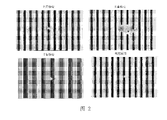
- Figure 2 is a schematic diagram of the impact of unfiltered photoresist on the product
- Fig. 3 is the overall flowchart of the monitoring method of the first embodiment of the present application.
- FIG. 4 is an overall flow chart of the monitoring method of the second embodiment of the present application.
- FIG. 5 is a structural schematic diagram of a photoresist supply system.
- 1 photoresist supply bottle
- 2 buffer
- 3 pump
- 4 photoresist filter
- 41 filter material
- 5 switching valve
- 6 nozzle
- 7 chip
- 8 inert gas supply part.
- FIG. 1 is a process diagram of filtering photoresist by the filter of the present application.
- the filter uses a filter material 41 with holes to filter the unfiltered photoresist, and the filter material filters out the particles in the unfiltered photoresist, and stays on the surface of the filter material or in the filter material, and is left
- the particles on the surface of the filter material or in the filter material are also called impurities in the photoresist.
- the filtering function of the filter is to remove impurities from the unfiltered photoresist, so that the unfiltered photoresist reaches the required cleanliness, which is the photoresist we use.
- the filter reaches a certain capacity, it will be saturated and become invalid.
- the impurities in the photoresist cannot be filtered out, and when it is sprayed on the chip, it will cause defects in the process graphics.
- the possible defects include several bridging forms shown in Figure 2.
- the size of the defect is about 1-1000um.
- the impact of the defect on the yield is fatal. Every photoresist used in the lithography process, All filters are required. The process requires at least 60 steps of photolithography coating, all of which may be affected by the filter.
- Fig. 3 is an overall flowchart of the monitoring method in the first embodiment of the present application.
- this embodiment provides a method for monitoring the life cycle of a photoresist filter, including:
- the photoresist filter traps particles in the photoresist to filter the photoresist
- the filtering state reaches the preset first threshold value, which may be the theoretical filtering volume of the filter, or 60% or 80% of the theoretical filtering volume, or the standard upper limit set by the filter manufacturer when leaving the factory.
- the standard upper limit set by the manufacturer is not set for a specific photoresist or flow rate, but a general standard value. Therefore, when the standard upper limit of the filtered amount and the used time is often used, the filter has not yet reached Limit, can also filter the photoresist, and filter clean, if the filter or filter is replaced when the standard upper limit of the filtered amount and the used time is used, the filter will often be wasted due to underutilization of resources, and The production cost and labor cost will be increased due to frequent disassembly and replacement of equipment.
- the state of particulate matter reaches the preset second threshold, it means that the photoresist filtered by the filter cannot meet the requirements of the use standard, that is, the filtered photoresist will cause defects in the chip, making the chip pass rate not up to standard when.
- the method for monitoring the life cycle of the photoresist filter in this embodiment firstly detects the filtering state, and then detects the state of the particulate matter when the filtering state reaches the preset first threshold value. According to whether the state of the particulate matter reaches the preset The second threshold value is determined to determine the service life of the photoresist filter.
- the process is simple, and the upper limit of the filter can be accurately detected through multi-level card control, which avoids product defects caused by exceeding the upper limit of use, and can make full use of the filter. devices, reducing waste and reducing equipment replacement costs.
- the method for monitoring the life cycle of the photoresist filter in this embodiment can be based on the data of the unfiltered photoresist (for example, data such as photoresist type, impurity type, impurity concentration, flow speed or process), and for different unfiltered photoresist
- the upper limit of the filtering amount and the upper limit of the use time (that is, the use cycle) obtained by the photoresist establish the relationship between the data of the unfiltered photoresist and the upper limit of the filter amount of the photoresist and the upper limit of the use time, so as to compare the unmeasured photoresist Predict the upper limit of filtration volume and usage time, and systematically control the service life of filters based on the predicted baseline filtration volume and usage time, so as to arrange filter replacement in advance to prevent defects, and at the same time, it can be pre-arranged in combination with machine maintenance time Or other machine scheduling, effectively reducing the impact on production capacity, avoiding the risk of emergency disconnection of the production line and the impact on the pass rate.
- the method for monitoring the life cycle of the photoresist filter in this embodiment can be based on the data of the unfiltered photoresist (for example, data such as photoresist type, impurity type, impurity concentration, flow speed or process) and filter type, As well as the reference filtering amount and reference use time obtained by different filters for different unfiltered photoresist, establish the data of unfiltered photoresist and filter type, and the relationship between the reference filter amount and reference use time of photoresist (It can be a functional relationship) to predict the upper limit of the filtering capacity and the upper limit of the use time of the filter, based on the upper limit of the filtering capacity and the upper limit of the use time, to systematically control the service life of the filter, so as to arrange the replacement of the filter in advance to prevent defects , At the same time, it can be pre-arranged in combination with machine maintenance time or other machine schedules to effectively reduce the impact on production capacity, avoid the risk of emergency disconnection of the production line and the impact on the pass rate.
- the method for monitoring the life cycle of the light-blocking filter further includes: sending an alarm to the current filtering state, so as to prompt to stop running the light-blocking filter. In order to prevent the light blocking filter from being used when it exceeds the upper limit of use.
- acquiring the filtering state of the light-blocking filter includes: acquiring the filtering state of the light-blocking filter in real time, or acquiring the filtering state of the light-blocking filter periodically. The details can be determined according to production and testing requirements.
- the filtering state is a filtering amount of the light blocking filter
- the first thresholds are respectively preset filtering amount values.
- the first threshold may be determined by a standard upper limit of the filtering capacity set by the manufacturer when leaving the factory, or it may be a theoretical filtering capacity of the filter or the like.
- the filtering state is the filtering time of the light blocking filter
- the first thresholds are respectively preset filtering time values.
- the first threshold can be determined by the standard upper limit of the filtering time set by the manufacturer when leaving the factory, or it can be the theoretical filtering time of the filter, etc.
- the filtering state includes the filtering time and filtering amount of the light blocking filter
- the first threshold includes a preset filtering time value and filtering amount value
- it is judged whether the filtering state is Reaching the preset first threshold includes: judging the first threshold by reaching one of the preset filtering time value and filtering amount earlier.
- the manufacturer can set the standard upper limit of the filtration amount and filtration time together to make the judgment so as to make the result accurate.
- the state of the particles includes the number of particles and/or the particle size of the particles. That is, it is judged by the number of particles and the particle size of particles together, or by using one of them.
- the state of particulate matter is detected by a routine measuring machine, and the preset second threshold is based on the basic level of the routine measuring machine.
- the second threshold can also be the degree of change in the state of particulate matter per unit time , the number or particle size of the particles per unit time does not change, it is determined that the filter has entered an invalid state, and the accuracy of monitoring the photoresist filter is improved.
- obtaining the state of the particles in the light blocking filter includes: obtaining the state of the particles in the light blocking filter in real time; or, periodically obtaining the state of the particles in the light blocking filter status. The details can be determined according to production and testing requirements.
- FIG. 4 is an overall flow chart of the detection method according to the second embodiment of the present application.
- this embodiment provides a method for monitoring the life cycle of a photoresist filter, including:
- the photoresist filter traps particles in the photoresist to filter the photoresist
- the safety threshold is a filtering state value of the filter when the state of the particulate matter reaches a preset state.
- the method for monitoring the life cycle of the photoresist filter in this embodiment can judge the life cycle of the filter when the safety threshold of the filter is known, so that the life cycle of the filter can be accurately judged, and much Second judgment, and can arrange filter replacement in advance according to the service cycle to prevent defects. At the same time, it can be pre-arranged in combination with machine maintenance time or other machine schedules to effectively reduce the impact on production capacity and avoid the risk of emergency disconnection of the production line. and its impact on yield.
- the filtering state includes filtering amount and/or filtering time, that is, the filtering state is judged through the filtering amount and filtering time together, or the filtering state is judged through one of them.
- This embodiment provides a monitoring system for the life cycle of a photoresist filter.
- the monitoring system monitors the photoresist filter.
- the photoresist filter traps particles in the photoresist to filter the photoresist.
- the monitoring The system includes:
- the first data collection unit acquires the filtering state value of the photoresist filter
- the first comparison unit is used to extract the preset first threshold in the database, and compare it with the filtering state value obtained by the first data collection unit, and judge whether the filtering state reaches the preset value first threshold;
- the first output unit outputs the comparison result of the first comparison unit to the photoresist filter, and drives and adjusts the photoresist filter;
- a second data collection unit for acquiring the state value of the particles in the light blocking filter
- the second comparison unit is used to extract the preset second threshold value in the database, and compare it with the state value of the particulate matter, to determine whether the state of the particulate matter reaches the preset second threshold value;
- the second output unit outputs the comparison result of the second comparison unit to the photoresisting filter, and drives and adjusts the photoresisting filter.
- the monitoring system for the life cycle of the photoresist filter in this embodiment firstly detects the filtering state, and then detects the state of the particulate matter when the filtering state reaches the preset first threshold value. According to whether the state of the particulate matter reaches the preset The second threshold value is determined to determine the life cycle of the photoresist filter.
- the process is simple, and the upper limit of the filter can be accurately detected, which avoids product defects caused by exceeding the upper limit of use, and can make full use of the filter to reduce waste. At the same time Reduce equipment replacement costs.
- the monitoring system of the life cycle of the photoresist filter in this embodiment can be based on the data of the unfiltered photoresist (for example, data such as photoresist type, impurity type, impurity concentration, flow speed or process), and for different unfiltered photoresist
- the upper limit of the filtering amount and the upper limit of the use time (that is, the use cycle) obtained by the photoresist establish the relationship between the data of the unfiltered photoresist and the upper limit of the filter amount of the photoresist and the upper limit of the use time, so as to compare the unmeasured photoresist Predict the upper limit of filtration volume and usage time, and systematically control the service life of filters based on the predicted baseline filtration volume and usage time, so as to arrange filter replacement in advance to prevent defects, and at the same time, it can be pre-arranged in combination with machine maintenance time Or other machine scheduling, effectively reducing the impact on production capacity, avoiding the risk of emergency disconnection of the production line and the impact on the pass rate.
- the method for monitoring the life cycle of the photoresist filter in this embodiment can be based on the data of the unfiltered photoresist (for example, data such as photoresist type, impurity type, impurity concentration, flow speed or process) and filter type, As well as the reference filtering amount and reference use time obtained by different filters for different unfiltered photoresist, establish the data of unfiltered photoresist and filter type, and the relationship between the reference filter amount and reference use time of photoresist (It can be a functional relationship) to predict the upper limit of the filtering capacity and the upper limit of the use time of the filter, based on the upper limit of the filtering capacity and the upper limit of the use time, to systematically control the service life of the filter, so as to arrange the replacement of the filter in advance to prevent defects , At the same time, it can be pre-arranged in combination with machine maintenance time or other machine schedules to effectively reduce the impact on production capacity, avoid the risk of emergency disconnection of the production line and the impact on the pass rate.
- the monitoring system for the life cycle of the light blocking filter further includes: the monitoring system includes an alarm unit, and the alarm unit sends an alarm to the current filtering state to prompt to stop the operation of the light blocking filter . In order to prevent the light blocking filter from being used when it exceeds the upper limit of use.
- the first comparison unit includes: a real-time first comparison unit, configured to acquire the filtering state of the light blocking filter in real time.
- the first comparison unit includes: a timing first comparison unit, configured to regularly acquire the filtering state of the light blocking filter.
- the filtering state is a filtering amount of the light blocking filter
- the first thresholds are respectively preset filtering amount values. That is to say, it is judged by the standard upper limit of the filtration volume set by the manufacturer when leaving the factory.
- the filtering state is the filtering time of the light blocking filter
- the first thresholds are respectively preset filtering time values. That is, it is determined by the standard upper limit of the filtration time set by the manufacturer when leaving the factory.
- the filtering state includes the filtering time and filtering amount of the light blocking filter
- the first threshold includes a preset filtering time value and filtering amount value
- it is judged whether the filtering state is Reaching the preset first threshold includes: judging the first threshold by reaching one of the preset filtering time value and filtering amount earlier. That is to say, the manufacturer sets the standard upper limit of the filtration amount and the filtration time together to make the judgment so that the result is accurate.
- the state of the particles includes the number of particles and/or the particle size of the particles. That is, it is judged by the number of particles and the particle size of particles together, or by using one of them. Specifically, there will be a routine measuring machine on the production line to detect the state of particulate matter through the routine measuring machine, and the preset second threshold is based on the basic level value of the routine measuring machine.
- the second comparison unit includes: a real-time second comparison unit, configured to acquire the state of the particles in the light blocking filter in real time.
- the second comparison unit includes: a timing second comparison unit, configured to regularly acquire the state of the particles in the light blocking filter.
- This implementation manner is the same as the first implementation manner or the second implementation manner, which will not be repeated here.
- FIG. 5 is a schematic structural diagram of a photoresist supply system.
- the photoresist is filtered and supplied through the supply system in the figure, and the photoresist supply system can be applied to a coating developing machine, for example, wherein the photoresist supply system includes: a photoresist supply bottle 1, a buffer 2, Pump 3, photoresist filter 4, switch valve 5, nozzle 6, monitoring system and control system of the third embodiment.
- the photoresist supply system includes: a photoresist supply bottle 1, a buffer 2, Pump 3, photoresist filter 4, switch valve 5, nozzle 6, monitoring system and control system of the third embodiment.
- the photoresist supply bottle 1 accommodates the photoresist to be filtered;
- the buffer 2 is connected to the photoresist supply bottle 1, and the photoresist to be filtered is temporarily stored in the buffer 2;
- the pump 3 is connected to the The buffer 2, the pump 3 pumps the photoresist to be filtered temporarily stored in the buffer 2;
- the photoresist filter 4 is connected to the pump 3 to suck the photoresist to be filtered by the pump 3
- the filtered photoresist is filtered to obtain the filtered photoresist;
- the switch valve 5 is connected to the photoresist filter 4;
- the nozzle 6 is connected to the switch valve 5, and the filtered photoresist is sprayed to the object to be coated Above;
- a monitoring system connected to the photoresist filter in communication, and the monitoring system monitors the service period of the photoresist filter;
- a control system connected to the pump 3 and the switch valve 5 in communication, to control the The pump 3 and the switch valve 5.
- the supply system further includes: an inert gas supply part 8, connected to the photoresist supply bottle 1, passing inert gas into the photoresist to be filtered to push out the air in the bottle, Form a vacuum state, in which the inert gas can be N2.
- This embodiment also provides a storage medium, on which a computer program is stored, and when the program is executed by a processor, the method for monitoring the life cycle of a photoresist filter as provided in the first embodiment or the second embodiment of the present application is realized .
- This embodiment also provides an electronic device, including a memory, a processor, and a computer program stored in the memory and operable on the processor.
- the processor executes the program, it implements the first embodiment or the second embodiment of the present application.
- the monitoring method of the life cycle of the photoresist filter provided by the method.
- the embodiments of the present application may be provided as methods, systems, or computer program products. Accordingly, the present application may take the form of an entirely hardware embodiment, an entirely software embodiment, or an embodiment combining software and hardware aspects. Furthermore, the present application may take the form of a computer program product embodied on one or more computer-usable storage media (including but not limited to disk storage, CD-ROM, optical storage, etc.) having computer-usable program code embodied therein.
- computer-usable storage media including but not limited to disk storage, CD-ROM, optical storage, etc.
- These computer program instructions may also be stored in a computer-readable memory capable of directing a computer or other programmable data processing apparatus to operate in a specific manner, such that the instructions stored in the computer-readable memory produce an article of manufacture comprising instruction means, the instructions
- the device realizes the function specified in one or more procedures of the flowchart and/or one or more blocks of the block diagram.
- the storage medium may be a magnetic disk, an optical disk, a read-only memory (Read-Only Memory, ROM for short), or a random access memory (Random Access Memory, RAM for short).
- the steps in the methods of the embodiments of the present application can be adjusted, combined and deleted according to actual needs.
- the modules in the system of the embodiment of the present application can be combined, divided and deleted according to actual needs.
Landscapes
- Physics & Mathematics (AREA)
- General Physics & Mathematics (AREA)
- Chemical & Material Sciences (AREA)
- Chemical Kinetics & Catalysis (AREA)
- Materials For Photolithography (AREA)
Abstract
本申请公开了一种光阻过滤器使用周期的监控方法、系统及光阻供给系统,其中,监控方法,包括:提供一光阻过滤器,所述光阻过滤器截留光阻内的颗粒物,以过滤所述光阻;运行所述光阻过滤器;获取所述光阻过滤器的过滤状态,并判断所述过滤状态是否达到预设定的第一阈值;如果否,返回继续运行所述光阻过滤器;如果是,获取所述光阻过滤器内所述颗粒物的状态;判断所述颗粒物的状态是否达到预设定的第二阈值;如果否,返回继续运行所述光阻过滤器;如果是,停止运行所述光阻过滤器,并抓取所述光阻过滤器当前的过滤状态为所述光阻过滤器使用周期。本申请监控方法过程简单,且能够准确的检测出过滤器的使用周期。
Description
交叉引用
本申请基于申请号为2021109557951、申请日为2021年08月19日的中国专利申请提出,并要求该中国专利申请的优先权,该中国专利申请的全部内容在此引入本申请作为参考。
本申请涉及半导体制造领域,特别涉及一种光阻过滤器使用周期的监控方法、系统及光阻供给系统。
在半导体晶片或液晶用玻璃基板等的表面上,由光刻工序和蚀刻工序制作微细电路图案。在光刻工序中,使用光阻供给装置将光阻(也被称为光刻胶)等液体涂覆在晶片或玻璃基板的表面上,收容在供给瓶内的光阻通过泵抽吸并通过过滤器等从喷嘴涂覆到晶片等被涂覆物上。目前,光阻的供给系统中,光阻过滤器一般是根据厂商的建议定义使用周期,而不能准确获取过滤器的使用周期,这往往导致过滤器未充分发挥过滤功能即被丢弃,造成资源浪费,或者导致过度使用过滤器而致使光阻在被涂覆物上出现图形缺陷,影响到最终半导体产品的合格率和质量,也同时影响半导体制程工艺的产线、生产率情况。
发明内容
鉴于此,本申请实施例的目的是提供一种光阻过滤器使用周期的监控方法、系统及光阻供给系统,根据本申请实施例可以有效并准确 的定义出所述光阻过滤器使用周期,从而降低半导体产品的缺陷。
本申请的一些实施例提供了一种光阻过滤器使用周期的监控方法,包括:提供一光阻过滤器,所述光阻过滤器截留光阻内的颗粒物,以过滤所述光阻;运行所述光阻过滤器;获取所述光阻过滤器的过滤状态,并判断所述过滤状态是否达到预设定的第一阈值;如果否,返回继续运行所述光阻过滤器;如果是,获取所述光阻过滤器内所述颗粒物的状态;判断所述颗粒物的状态是否达到预设定的第二阈值;如果否,返回继续运行所述光阻过滤器;如果是,停止运行所述光阻过滤器,并抓取所述光阻过滤器当前的过滤状态为所述光阻过滤器使用周期。
在一些实施例中,所述方法还包括:对所述当前的过滤状态发出警报,以提示停止运行所述光阻过滤器。
在一些实施例中,所述获取所述光阻过滤器的过滤状态为包括:实时获取所述光阻过滤器的过滤状态;或,定时获取所述光阻过滤器的过滤状态。
在一些实施例中,所述过滤状态为所述光阻过滤器的过滤量或过滤时间,所述第一阈值分别为预设定过滤量值或过滤时间值。
在一些实施例中,所述过滤状态包括所述光阻过滤器的过滤时间和过滤量,所述第一阈值包括预设定的过滤时间值和过滤量值;其中,判断所述过滤状态是否达到预设定的第一阈值包括:以更先达到所述预设定的过滤时间值和过滤量值中的一者进行所述第一阈值的判断。
在一些实施例中,所述颗粒物的状态包括颗粒物的数量和/或颗 粒物的粒径。
在一些实施例中,获取所述光阻过滤器内所述颗粒物的状态包括:
实时获取所述光阻过滤器内所述颗粒物的状态;或,
定时获取所述光阻过滤器内所述颗粒物的状态。
本申请的一些实施例还提供了一种光阻过滤器使用周期的监控系统,所述监控系统监控光阻过滤器,所述光阻过滤器截留光阻内的颗粒物,以过滤所述光阻,所述监控系统包括:第一数据收集单元,获取所述光阻过滤器的过滤状态值;第一比对单元,用于提取数据库中预设定的第一阈值,并和所述第一数据收集单元获取的所述过滤状态值进行比对,判断所述过滤状态是否达到预设定的第一阈值;如果否,返回继续运行所述光阻过滤器;如果是,获取所述光阻过滤器内所述颗粒物的状态值;第一输出单元,将所述第一比对单元的比对结果输出至所述光阻过滤器,驱动调整所述光阻过滤器;第二数据收集单元,获取所述光阻过滤器内所述颗粒物的状态值;第二比对单元,用于提取数据库中预设定的第二阈值,并和所述颗粒物的状态值进行比对,判断所述颗粒物的状态是否达到所述预设定的第二阈值;如果否,返回继续运行所述光阻过滤器;如果是,停止运行所述光阻过滤器,并抓取所述光阻过滤器当前的过滤状态为所述光阻过滤器使用周期;第二输出单元,将所述第二比对单元的比对结果输出至所述光阻过滤器,驱动调整所述光阻过滤器。
在一些实施例中,所述监控系统包括报警单元,所述报警单元对 所述当前的过滤状态发出警报,以提示停止运行所述光阻过滤器。
本申请的一些实施例还一种光阻供给系统,所述供给系统包括:光阻供给瓶,容纳有待过滤的光阻;缓冲器,连接所述光阻供给瓶,所述待过滤的光阻暂存于所述缓冲器内;泵,连接所述缓冲器,所述泵抽吸所述缓冲器内暂存的所述待过滤的光阻;光阻过滤器,连接所述泵,以将所述泵抽吸的待过滤的光阻进行过滤,得到过滤后的光阻;开关阀,连接光阻过滤器;喷嘴,连接所述开关阀,喷送所述过滤后的光阻至到被涂覆物上;上述监控系统,通讯连接于所述光阻过滤器,所述监控系统监控所述光阻过滤器的使用周期;控制系统,通讯连接于所述泵和所述开关阀,以控制所述泵和所述开关阀。
在一些实施例中,所述供给系统还包括:惰性气体供给部,连接于所述光阻供给瓶,以向所述待过滤的光阻内通入惰性气体。
在一些实施例中,所述喷嘴包括一容纳腔,以暂存所述过滤后的光阻。
本申请实施例提供了一种光阻过滤器使用周期的监控方法,所述监控方法通过对过滤器的过滤量和过滤时间等过滤状态进行监控之外,还包括对过滤器内的颗粒物状态进行监控,从而精准地定义出过滤器的使用周期,即,定义过滤量上限和使用时间上限,过程简单,避免了因超过使用上限而导致产品缺陷,同时减少过滤器更换费用。
图1是本申请过滤器过滤光阻中的过程图;
图2是未过滤完全的光阻对产品产生影响的示意图
图3是本申请第一实施方式的监控方法的总体流程图;
图4是是本申请第二实施方式的监控方法的总体流程图;
图5是光阻供给系统的结构示意图。
附图标记:
1:光阻供给瓶;2:缓冲器;3:泵;4:光阻过滤器;41:滤材;5:开关阀;6:喷嘴;7:芯片;8;惰性气体供给部。
为使本申请的目的、技术方案和优点更加清楚明了,下面结合具体实施方式并参照附图,对本申请进一步详细说明。应该理解,这些描述只是示例性的,而并非要限制本申请的范围。此外,在以下说明中,省略了对公知结构和技术的描述,以避免不必要地混淆本申请的概念。
显然,所描述的实施例是本申请一部分实施例,而不是全部的实施例。基于本申请中的实施例,本领域普通技术人员在没有做出创造性劳动前提下所获得的所有其他实施例,都属于本申请保护的范围。
此外,下面所描述的本申请不同实施方式中所涉及的技术特征只要彼此之间未构成冲突就可以相互结合。
在本申请的描述中,需要说明的是,术语“第一”、“第二”、“第三”仅用于描述目的,而不能理解为指示或暗示相对重要性。
图1是本申请过滤器过滤光阻中的过程图。
参见图1,过滤器使用带孔的滤材41来对未过滤的光阻进行过滤,滤材将未过滤的光阻中的颗粒物过滤出来,留在滤材表面或滤材内,被留在滤材表面或滤材内的颗粒物,也被称为光阻内杂质。
过滤器的过滤功能是从未过滤的光阻中除去杂质,使未过滤的光阻达到所需的洁净度,就是我们使用的光阻。当过滤器过滤达到一定容量时,就会饱和而失效,此时光阻中的杂质就无法滤除干净,喷涂于芯片上时会造成工艺图形产生缺陷。可能产生的缺陷包括图2中显示的几种桥接形式,其中,缺陷大小约介于1~1000um,缺陷的产生对于合格率的影响是致命的,光刻工艺所使用的每一种光阻,皆需使用过滤器。在工艺上需要经过光刻涂布至少60个步骤,都可能受到过滤器的影响。
第一实施方式
图3是本申请第一实施方式的监控方法的总体流程图。
参见图3,本实施方式提供了一种光阻过滤器使用周期的监控方法,包括:
提供一光阻过滤器,所述光阻过滤器截留光阻内的颗粒物,以过滤所述光阻;
运行所述光阻过滤器;
获取所述光阻过滤器的过滤状态,并判断所述过滤状态是否达到预设定的第一阈值;
如果否,返回继续运行所述光阻过滤器;
如果是,获取所述光阻过滤器内所述颗粒物的状态;
判断所述颗粒物的状态是否达到预设定的第二阈值;
如果否,返回继续运行所述光阻过滤器;
如果是,停止运行所述光阻过滤器,并抓取所述光阻过滤器当前的过滤状态为所述光阻过滤器使用周期。
其中,过滤状态达到预设定的第一阈值可以是过滤器理论过滤量,或者理论过滤量的60%、80%,还可以是过滤器生产厂商在出厂时设定的标准上限,由于这个生产厂商设定的标准上限并不是针对特定的光阻或是流动速率来设定的,只是通用的标准值,故而在已过滤量和已使用时间的标准上限时,往往其中的过滤器还未达到极限,还能对光阻进行过滤,并过滤干净,如果在已过滤量和已使用时间的标准上限时就对或过滤器进行更换,往往会因资源未充分利用而对过滤器造成浪费,并且会因频繁拆卸设备和更换设备而造成生产成本和人力成本上的增加。
颗粒物的状态是否达到预设定的第二阈值的时候,为过滤器过滤后的光阻无法满足使用标准需要的时候,即过滤后的光阻会使芯片产生缺陷,使得芯片合格率不达标的时候。
本实施方式的光阻过滤器使用周期的监控方法,通过先对过滤状态达进行检测,在过滤状态达到预设定的第一阈值时再进行颗粒物的状态检测,根据颗粒物的状态是否达到预设定的第二阈值来确定光阻过滤器使用周期,过程简单,且经过多层级的卡控能够准确的检测出过滤器的使用上限,避免了因超过使用上限而导致产品缺陷,可以 充分利用过滤器,减少浪费,同时减少设备更换费用。
本实施方式的光阻过滤器使用周期的监控方法,可以根据未过滤的光阻的数据(例如,光阻种类、杂质类型、杂质浓度、流动速度或制程等数据),以及针对不同未过滤的光阻所得到的过滤量上限和使用时间上限(即使用周期),建立未过滤的光阻的数据和光阻的过滤量上限及使用时间上限之间的关系,以对未进行测量的光阻的过滤量上限和使用时间上限进行预测,基于预测的基准过滤量和基准使用时间,对过滤器使用期限进行系统控制,以便提前安排更换过滤器,防止缺陷产生,同时可预先安排结合机台保养时间或其他机台排程,有效降低对生产产能的影响,避免产线紧急断线的风险以及对合格率的影响。此外,本实施方式的光阻过滤器使用周期的监控方法,可以根据未过滤的光阻的数据(例如,光阻种类、杂质类型、杂质浓度、流动速度或制程等数据)和过滤器类型,以及不同过滤器针对不同未过滤的光阻所得到的基准过滤量和基准使用时间,建立未过滤的光阻的数据和过滤器类型,以及光阻的基准过滤量和基准使用时间之间的关系(可以是函数关系),以对过滤器的过滤量上限以及使用时间上限进行预测,基于过滤量上限以及使用时间上限,对过滤器使用期限进行系统控制,以便提前安排更换过滤器,防止缺陷产生,同时可预先安排结合机台保养时间或其他机台排程,有效降低对生产产能的影响,避免产线紧急断线的风险以及对合格率的影响。
在一些实施例中,光阻过滤器使用周期的监控方法还包括:对所述当前的过滤状态发出警报,以提示停止运行所述光阻过滤器。以防 止光阻过滤器超过使用上限时还进行使用。
在一些实施例中,上述获取所述光阻过滤器的过滤状态包括:实时获取所述光阻过滤器的过滤状态,或是定时获取所述光阻过滤器的过滤状态。具体可根据生产和检测需求来确定。
在一些实施例中,所述过滤状态为所述光阻过滤器的过滤量,所述第一阈值分别为预设定过滤量值。该第一阈值可以是通过生产厂商在出厂时设定过滤量的标准上限来进行判定,还可以是过滤器理论过滤量等。
在一些实施例中,所述过滤状态为所述光阻过滤器的过滤时间,所述第一阈值分别为预设定过滤时间值。该第一阈值可以是通过生产厂商在出厂时设定过滤时间的标准上限来进行判定,还可以是过滤器理论过滤时间等。
在一些实施例中,所述过滤状态包括所述光阻过滤器的过滤时间和过滤量,所述第一阈值包括预设定的过滤时间值和过滤量值;其中,判断所述过滤状态是否达到预设定的第一阈值包括:以更先达到所述预设定的过滤时间值和过滤量值中的一者进行所述第一阈值的判断。例如可以是通过生产厂商在出厂时设定过滤量和过滤时间的标准上限共同来进行判定,以使结果准确。
在一些实施例中,所述颗粒物的状态包括颗粒物的数量和/或颗粒物的粒径。即通过颗粒物的数量和颗粒物的粒径共同来进行判断,或是使用其中之一来进行判断。例如通过例行性测机对颗粒物的状态进行检测,预设定的第二阈值以例行性测机的基本水平值为基准,当 然,第二阈值也可以是单位时间内颗粒物状态的变化程度,单位时间内颗粒物的数量或者粒径不再改变,判定所述过滤器进入失效状态,提高光阻过滤器监控的准确性。
在一些实施例中,获取所述光阻过滤器内所述颗粒物的状态包括:实时获取所述光阻过滤器内所述颗粒物的状态;或,定时获取所述光阻过滤器内所述颗粒物的状态。具体可根据生产和检测需求来确定。
第二实施方式
图4是本申请第二实施方式的侦测方法的总体流程图。
参见图4,本实施方式提供了一种光阻过滤器使用周期的监控方法,包括:
提供一光阻过滤器,所述光阻过滤器截留光阻内的颗粒物,以过滤所述光阻;
运行所述光阻过滤器;
获取所述光阻过滤器的过滤状态,并判断所述过滤状态是否达到预设定的安全阈值;
如果否,返回继续运行所述光阻过滤器;
如果是,停止运行所述光阻过滤器;其中,所述安全阈值为所述颗粒物的状态达到预设状态时,所述过滤器的过滤状态值。
本实施方式的光阻过滤器使用周期的监控方法,可以是在过滤器的安全阈值是已知的情况下进行过滤器使用周期的判断,能够准确判断出过滤器的使用周期,且减少了多次判断,并且能根据使用周期提 前安排更换过滤器,防止缺陷产生,同时可预先安排结合机台保养时间或其他机台排程,有效降低对生产产能的影响,避免产线紧急断线的风险以及对合格率的影响。
在一些实施例中,所述过滤状态包括过滤量和/或过滤时间,即通过过滤量和过滤时间一起进行过滤状态的判断,或通过其中之一进行过滤状态的进行过滤状态的判断。
第三实施方式
本实施方式提供了一种光阻过滤器使用周期的监控系统,所述监控系统监控光阻过滤器,所述光阻过滤器截留光阻内的颗粒物,以过滤所述光阻,所述监控系统包括:
第一数据收集单元,获取所述光阻过滤器的过滤状态值;
第一比对单元,用于提取数据库中预设定的第一阈值,并和所述第一数据收集单元获取的所述过滤状态值进行比对,判断所述过滤状态是否达到预设定的第一阈值;
如果否,返回继续运行所述光阻过滤器;
如果是,获取所述光阻过滤器内所述颗粒物的状态值;
第一输出单元,将所述第一比对单元的比对结果输出至所述光阻过滤器,驱动调整所述光阻过滤器;
第二数据收集单元,获取所述光阻过滤器内所述颗粒物的状态值;
第二比对单元,用于提取数据库中预设定的第二阈值,并和所述颗粒物的状态值进行比对,判断所述颗粒物的状态是否达到所述预设 定的第二阈值;
如果否,返回继续运行所述光阻过滤器;
如果是,停止运行所述光阻过滤器,并抓取所述光阻过滤器当前的过滤状态为所述光阻过滤器使用周期;
第二输出单元,将所述第二比对单元的比对结果输出至所述光阻过滤器,驱动调整所述光阻过滤器。
本实施方式的光阻过滤器使用周期的监控系统,通过先对过滤状态达进行检测,在过滤状态达到预设定的第一阈值时再进行颗粒物的状态检测,根据颗粒物的状态是否达到预设定的第二阈值来确定光阻过滤器使用周期,过程简单,且能够准确的检测出过滤器的使用上限,避免了因超过使用上限而导致产品缺陷,可以充分利用过滤器,减少浪费,同时减少设备更换费用。
本实施方式的光阻过滤器使用周期的监控系统,可以根据未过滤的光阻的数据(例如,光阻种类、杂质类型、杂质浓度、流动速度或制程等数据),以及针对不同未过滤的光阻所得到的过滤量上限和使用时间上限(即使用周期),建立未过滤的光阻的数据和光阻的过滤量上限及使用时间上限之间的关系,以对未进行测量的光阻的过滤量上限和使用时间上限进行预测,基于预测的基准过滤量和基准使用时间,对过滤器使用期限进行系统控制,以便提前安排更换过滤器,防止缺陷产生,同时可预先安排结合机台保养时间或其他机台排程,有效降低对生产产能的影响,避免产线紧急断线的风险以及对合格率的影响。此外,本实施方式的光阻过滤器使用周期的监控方法,可以根据 未过滤的光阻的数据(例如,光阻种类、杂质类型、杂质浓度、流动速度或制程等数据)和过滤器类型,以及不同过滤器针对不同未过滤的光阻所得到的基准过滤量和基准使用时间,建立未过滤的光阻的数据和过滤器类型,以及光阻的基准过滤量和基准使用时间之间的关系(可以是函数关系),以对过滤器的过滤量上限以及使用时间上限进行预测,基于过滤量上限以及使用时间上限,对过滤器使用期限进行系统控制,以便提前安排更换过滤器,防止缺陷产生,同时可预先安排结合机台保养时间或其他机台排程,有效降低对生产产能的影响,避免产线紧急断线的风险以及对合格率的影响。
在一些实施例中,光阻过滤器使用周期的监控系统还包括:所述监控系统包括报警单元,所述报警单元对所述当前的过滤状态发出警报,以提示停止运行所述光阻过滤器。以防止光阻过滤器超过使用上限时还进行使用。
在一些实施例中,第一比对单元包括:实时第一比对单元,用于实时获取所述光阻过滤器的过滤状态。
在一些实施例中,第一比对单元包括:定时第一比对单元,用于定时获取所述光阻过滤器的过滤状态。
在一些实施例中,所述过滤状态为所述光阻过滤器的过滤量,所述第一阈值分别为预设定过滤量值。即通过生产厂商在出厂时设定过滤量的标准上限来进行判定。
在一些实施例中,所述过滤状态为所述光阻过滤器的过滤时间,所述第一阈值分别为预设定过滤时间值。即通过生产厂商在出厂时设 定过滤时间的标准上限来进行判定。
在一些实施例中,所述过滤状态包括所述光阻过滤器的过滤时间和过滤量,所述第一阈值包括预设定的过滤时间值和过滤量值;其中,判断所述过滤状态是否达到预设定的第一阈值包括:以更先达到所述预设定的过滤时间值和过滤量值中的一者进行所述第一阈值的判断。即通过生产厂商在出厂时设定过滤量和过滤时间的标准上限共同来进行判定,以使结果准确。
在一些实施例中,所述颗粒物的状态包括颗粒物的数量和/或颗粒物的粒径。即通过颗粒物的数量和颗粒物的粒径共同来进行判断,或是使用其中之一来进行判断。具体来说,生产线上会有例行性测机,通过例行性测机对颗粒物的状态进行检测,预设定的第二阈值以例行性测机的基本水平值为基准。
在一些实施例中,第二比对单元,包括:实时第二比对单元,用于实时获取所述光阻过滤器内所述颗粒物的状态。
在一些实施例中,第二比对单元,包括:定时第二比对单元,用于定时获取所述光阻过滤器内所述颗粒物的状态。
本实施方式与第一实施方式或第二实施方式相同之处,在此不多做赘述。
第四实施方式
图5是光阻供给系统的结构示意图。
参见图5,通过图中的供给系统对光阻进行过滤、供给,该光阻供给系统例如可以适用于涂布显影机,其中,光阻供给系统包括:光 阻供给瓶1、缓冲器2、泵3、光阻过滤器4、开关阀5、喷嘴6、第三实施方式的监控系统和控制系统。其中,光阻供给瓶1,容纳有待过滤的光阻;缓冲器2,连接所述光阻供给瓶1,所述待过滤的光阻暂存于所述缓冲器2内;泵3,连接所述缓冲器2,所述泵3抽吸所述缓冲器2内暂存的所述待过滤的光阻;光阻过滤器4,连接所述泵3,以将所述泵3抽吸的待过滤的光阻进行过滤,得到过滤后的光阻;开关阀5,连接光阻过滤器4;喷嘴6,连接所述开关阀5,喷送所述过滤后的光阻至到被涂覆物上;监控系统,通讯连接于所述光阻过滤器,所述监控系统监控所述光阻过滤器的使用周期;控制系统,通讯连接于所述泵3和所述开关阀5,以控制所述泵3和所述开关阀5。若是需要使用光阻,则控制开关阀5和泵3,将光阻通过喷嘴6,喷涂于芯片7上。
在一些实施例中,所述供给系统还包括:惰性气体供给部8,连接于所述光阻供给瓶1,向所述待过滤的光阻内通入惰性气体,以将瓶内空气推出,形成一个真空状态,其中惰性气体可以是N2。
本实施方式还提供了一种存储介质,存储介质上存储有计算机程序,程序被处理器执行时实现如本申请的第一实施方式或第二实施方式提供的光阻过滤器使用周期的监控方法。
本实施方式还提供了一种电子设备,包括存储器、处理器及存储在存储器上并可在处理器上运行的计算机程序,处理器执行程序时实现如本申请的第一实施方式或第二实施方式提供的光阻过滤器使用周期的监控方法。
应当理解的是,本申请的上述具体实施方式仅仅用于示例性说明或解释本申请的原理,而不构成对本申请的限制。因此,在不偏离本申请的精神和范围的情况下所做的任何修改、等同替换、改进等,均应包含在本申请的保护范围之内。此外,本申请所附权利要求旨在涵盖落入所附权利要求范围和边界、或者这种范围和边界的等同形式内的全部变化和修改例。
本领域内的技术人员应明白,本申请的实施例可提供为方法、系统、或计算机程序产品。因此,本申请可采用完全硬件实施例、完全软件实施例、或结合软件和硬件方面的实施例的形式。而且,本申请可采用在一个或多个其中包含有计算机可用程序代码的计算机可用存储介质(包括但不限于磁盘存储器、CD-ROM、光学存储器等)上实施的计算机程序产品的形式。
本申请是参照根据本申请实施例的方法、设备(系统)、和计算机程序产品的流程图和/或方框图来描述的。应理解可由计算机程序指令实现流程图和/或方框图中的每一流程和/或方框、以及流程图和/或方框图中的流程和/或方框的结合。可提供这些计算机程序指令到通用计算机、专用计算机、嵌入式处理机或其他可编程数据处理设备的处理器以产生一个机器,使得通过计算机或其他可编程数据处理设备的处理器执行的指令产生用于实现在流程图一个流程或多个流程和/或方框图一个方框或多个方框中指定的功能的装置。
这些计算机程序指令也可存储在能引导计算机或其他可编程数据处理设备以特定方式工作的计算机可读存储器中,使得存储在该计 算机可读存储器中的指令产生包括指令装置的制造品,该指令装置实现在流程图一个流程或多个流程和/或方框图一个方框或多个方框中指定的功能。
这些计算机程序指令也可装载到计算机或其他可编程数据处理设备上,使得在计算机或其他可编程设备上执行一系列操作步骤以产生计算机实现的处理,从而在计算机或其他可编程设备上执行的指令提供用于实现在流程图一个流程或多个流程和/或方框图一个方框或多个方框中指定的功能的步骤。
本领域普通技术人员可以理解实现上述实施例方法中的全部或部分步骤是可以通过程序来指令相关硬件来完成,所述的程序可以存储于一计算机可读取存储介质中,该程序在执行时,包括如下如上述各方法的实施例的流程。其中,所述的存储介质可为磁碟、光盘、只读存储记忆体(Read-OnlyMemory,简称ROM)或随机存取存储器(RandomAccessMemory,简称RAM)等。
本申请实施例方法中的步骤可以根据实际需要进行顺序调整、合并和删减。本申请实施例系统中的模块可以根据实际需要进行合并、划分和删减。
Claims (12)
- 一种光阻过滤器使用周期的监控方法,包括:提供一光阻过滤器,所述光阻过滤器截留光阻内的颗粒物,以过滤所述光阻;运行所述光阻过滤器;获取所述光阻过滤器的过滤状态,并判断所述过滤状态是否达到预设定的第一阈值;如果否,返回继续运行所述光阻过滤器;如果是,获取所述光阻过滤器内所述颗粒物的状态;判断所述颗粒物的状态是否达到预设定的第二阈值;如果否,返回继续运行所述光阻过滤器;如果是,停止运行所述光阻过滤器,并抓取所述光阻过滤器当前的过滤状态为所述光阻过滤器使用周期。
- 根据权利要求1所述的光阻过滤器使用周期的监控方法,其中,所述方法还包括:对所述当前的过滤状态发出警报,以提示停止运行所述光阻过滤器。
- 根据权利要求1所述的光阻过滤器使用周期的监控方法,其中,所述获取所述光阻过滤器的过滤状态包括:实时获取所述光阻过滤器的过滤状态;或,定时获取所述光阻过滤器的过滤状态。
- 根据权利要求1~3任意一项所述的光阻过滤器使用周期的监控方法,其中,所述过滤状态为所述光阻过滤器的过滤量或过滤时间,所述第一阈值分别为预设定过滤量值或过滤时间值。
- 根据权利要求1所述的光阻过滤器使用周期的监控方法,其中,所述过滤状态包括所述光阻过滤器的过滤时间和过滤量,所述第一阈值包括预设定的过滤时间值和过滤量值;其中,判断所述过滤状态是否达到预设定的第一阈值包括:以更先达到所述预设定的过滤时间值和过滤量值中的一者进行所述第一阈值的判断。
- 根据权利要求1所述的光阻过滤器使用周期的监控方法,其中,所述颗粒物的状态包括颗粒物的数量和/或颗粒物的粒径。
- 根据权利要求1所述的光阻过滤器使用周期的监控方法,其中,所述获取所述光阻过滤器内所述颗粒物的状态包括:实时获取所述光阻过滤器内所述颗粒物的状态;或,定时获取所述光阻过滤器内所述颗粒物的状态。
- 一种光阻过滤器使用周期的监控系统,所述监控系统监控光阻过滤器,所述光阻过滤器截留光阻内的颗粒物,以过滤所述光阻,所述监控系统包括:第一数据收集单元,获取所述光阻过滤器的过滤状态值;第一比对单元,用于提取数据库中预设定的第一阈值,并和所述第一数据收集单元获取的所述过滤状态值进行比对,判断所述过滤状态是否达到预设定的第一阈值;如果否,返回继续运行所述光阻过滤器;如果是,获取所述光阻过滤器内所述颗粒物的状态值;第一输出单元,将所述第一比对单元的比对结果输出至所述光阻过滤器,驱动调整所述光阻过滤器;第二数据收集单元,获取所述光阻过滤器内所述颗粒物的状态值;第二比对单元,用于提取数据库中预设定的第二阈值,并和所述颗粒物的状态值进行比对,判断所述颗粒物的状态是否达到所述预设定的第二阈值;如果否,返回继续运行所述光阻过滤器;如果是,停止运行所述光阻过滤器,并抓取所述光阻过滤器当前的过滤状态为所述光阻过滤器使用周期;第二输出单元,将所述第二比对单元的比对结果输出至所述光阻过滤器,驱动调整所述光阻过滤器。
- 根据权利要求8所述的光阻过滤器使用周期的监控系统,其中,所述监控系统包括报警单元,所述报警单元对所述当前的过滤状态发出警报,以提示停止运行所述光阻过滤器。
- 一种光阻供给系统,所述供给系统包括:光阻供给瓶,容纳有待过滤的光阻;缓冲器,连接所述光阻供给瓶,所述待过滤的光阻暂存于所述缓冲器内;泵,连接所述缓冲器,所述泵抽吸所述缓冲器内暂存的所述待过滤的光阻;光阻过滤器,连接所述泵,以将所述泵抽吸的待过滤的光阻进行过滤,得到过滤后的光阻;开关阀,连接光阻过滤器;喷嘴,连接所述开关阀,喷送所述过滤后的光阻至到被涂覆物上;如权利要求8或9所述的监控系统,通讯连接于所述光阻过滤器,所述监控系统监控所述光阻过滤器的使用周期;控制系统,通讯连接于所述泵和所述开关阀,以控制所述泵和所述开关阀。
- 根据权利要求10所述的光阻供给系统,其中,所述供给系统还包括:惰性气体供给部,连接于所述光阻供给瓶,以向所述待过滤的光阻内通入惰性气体。
- 根据权利要求10所述的光阻供给系统,其中,所述喷嘴包括一容纳腔,以暂存所述过滤后的光阻。
Applications Claiming Priority (2)
| Application Number | Priority Date | Filing Date | Title |
|---|---|---|---|
| CN202110955795.1A CN115869671B (zh) | 2021-08-19 | 2021-08-19 | 光阻过滤器使用周期的监控方法、系统及光阻供给系统 |
| CN202110955795.1 | 2021-08-19 |
Publications (1)
| Publication Number | Publication Date |
|---|---|
| WO2023019783A1 true WO2023019783A1 (zh) | 2023-02-23 |
Family
ID=85239987
Family Applications (1)
| Application Number | Title | Priority Date | Filing Date |
|---|---|---|---|
| PCT/CN2021/131988 Ceased WO2023019783A1 (zh) | 2021-08-19 | 2021-11-22 | 光阻过滤器使用周期的监控方法、系统及光阻供给系统 |
Country Status (2)
| Country | Link |
|---|---|
| CN (1) | CN115869671B (zh) |
| WO (1) | WO2023019783A1 (zh) |
Citations (4)
| Publication number | Priority date | Publication date | Assignee | Title |
|---|---|---|---|---|
| TW422719B (en) * | 1998-10-22 | 2001-02-21 | Promos Technologies Inc | Method of detecting timing in changing filter |
| JP2003315461A (ja) * | 2002-04-19 | 2003-11-06 | Fuji Electric Co Ltd | 放射性ダストモニタ及び放射性ダストモニタ用濾紙リサイクル可否判定装置 |
| CN101271276A (zh) * | 2007-03-20 | 2008-09-24 | 台湾积体电路制造股份有限公司 | 更换光阻过滤器的系统与方法 |
| CN208984111U (zh) * | 2018-10-16 | 2019-06-14 | 上海华力集成电路制造有限公司 | 一种监控光阻过滤器使用寿命的系统 |
Family Cites Families (8)
| Publication number | Priority date | Publication date | Assignee | Title |
|---|---|---|---|---|
| KR19990064658A (ko) * | 1999-04-26 | 1999-08-05 | 김용선 | 역삼투압 정수기의 필터교환 경보장치 및 그 방법 |
| TW201015228A (en) * | 2008-10-15 | 2010-04-16 | Hweju Tratek Co Ltd | Pre-wet system for photoresist filter |
| JP6201822B2 (ja) * | 2014-03-05 | 2017-09-27 | トヨタ自動車株式会社 | 内燃機関の排気浄化システム及び、内燃機関の排気浄化システムのフィルタ故障判定方法 |
| TWM520721U (zh) * | 2015-09-04 | 2016-04-21 | 慧竹開發有限公司 | 光阻噴吐系統 |
| CN105091250B (zh) * | 2015-09-17 | 2018-03-06 | 北京金山安全软件有限公司 | 净化器滤网过期提示方法和装置及净化器 |
| CN205090507U (zh) * | 2015-09-30 | 2016-03-16 | 飞利浦(中国)投资有限公司 | 空气净化设备 |
| CN107265535B (zh) * | 2017-08-18 | 2020-11-03 | 宁波福特恩净水设备有限公司 | 纯水机及过滤器 |
| CN108050649B (zh) * | 2017-11-03 | 2019-08-27 | 珠海格力电器股份有限公司 | 空调过滤网检测方法、装置、存储介质及空调 |
-
2021
- 2021-08-19 CN CN202110955795.1A patent/CN115869671B/zh active Active
- 2021-11-22 WO PCT/CN2021/131988 patent/WO2023019783A1/zh not_active Ceased
Patent Citations (4)
| Publication number | Priority date | Publication date | Assignee | Title |
|---|---|---|---|---|
| TW422719B (en) * | 1998-10-22 | 2001-02-21 | Promos Technologies Inc | Method of detecting timing in changing filter |
| JP2003315461A (ja) * | 2002-04-19 | 2003-11-06 | Fuji Electric Co Ltd | 放射性ダストモニタ及び放射性ダストモニタ用濾紙リサイクル可否判定装置 |
| CN101271276A (zh) * | 2007-03-20 | 2008-09-24 | 台湾积体电路制造股份有限公司 | 更换光阻过滤器的系统与方法 |
| CN208984111U (zh) * | 2018-10-16 | 2019-06-14 | 上海华力集成电路制造有限公司 | 一种监控光阻过滤器使用寿命的系统 |
Also Published As
| Publication number | Publication date |
|---|---|
| CN115869671A (zh) | 2023-03-31 |
| CN115869671B (zh) | 2025-11-14 |
Similar Documents
| Publication | Publication Date | Title |
|---|---|---|
| CN105729229B (zh) | 具备确认有无异物的视觉传感器的加工装置 | |
| JP2023036702A (ja) | クーラント液処理システム | |
| KR101760979B1 (ko) | 자외선 감시 시스템, 방법, 및 디바이스 | |
| CN105363277B (zh) | 胶印润版液自循环净化系统及净化方法 | |
| WO2020187221A1 (zh) | 空气净化器滤网寿命判断方法和空气净化器 | |
| WO2023019783A1 (zh) | 光阻过滤器使用周期的监控方法、系统及光阻供给系统 | |
| US20220112692A1 (en) | Air Filter Deterioration Determination Device of Construction Machine | |
| CN112032927A (zh) | 一种滤网更换提示方法、装置及气体净化设备 | |
| CN203881708U (zh) | 表面破损检测装置 | |
| CN101364046A (zh) | 液体与液位的侦测预警系统及方法 | |
| KR100393289B1 (ko) | 포토레지스트 토출 감시장치 | |
| CN113340776A (zh) | 物料搬送系统、自动化天车走行区域微粒监控系统及监控方法 | |
| CN117531307A (zh) | 防尘清扫控制装置、方法、充电桩及存储介质 | |
| JP2001120966A (ja) | 膜ろ過システム | |
| JP2007266211A (ja) | 半導体製造装置及び半導体製造方法 | |
| JPS63137430A (ja) | 半導体製造装置 | |
| JP2005000894A (ja) | フィルタ管理装置、フィルタ管理方法および基板の処理装置 | |
| CN222421890U (zh) | 监测晶圆处理设备中颗粒的装置 | |
| CN106338846B (zh) | 湿式设备 | |
| CN109512332A (zh) | 一种吸尘设备及其控制装置及方法 | |
| CN110838461A (zh) | 净化处理装置及净化处理方法 | |
| KR100922553B1 (ko) | 반도체 소자 제조 장치 | |
| CN205533561U (zh) | 一种手术床油液透析系统 | |
| JP2013202605A (ja) | 洗浄装置及び方法 | |
| JP3200999U (ja) | 検出装置付きのチップ排出装置 |
Legal Events
| Date | Code | Title | Description |
|---|---|---|---|
| 121 | Ep: the epo has been informed by wipo that ep was designated in this application |
Ref document number: 21954018 Country of ref document: EP Kind code of ref document: A1 |
|
| NENP | Non-entry into the national phase |
Ref country code: DE |
|
| 122 | Ep: pct application non-entry in european phase |
Ref document number: 21954018 Country of ref document: EP Kind code of ref document: A1 |