WO2023013181A1 - 鉱山管理システム - Google Patents
鉱山管理システム Download PDFInfo
- Publication number
- WO2023013181A1 WO2023013181A1 PCT/JP2022/017536 JP2022017536W WO2023013181A1 WO 2023013181 A1 WO2023013181 A1 WO 2023013181A1 JP 2022017536 W JP2022017536 W JP 2022017536W WO 2023013181 A1 WO2023013181 A1 WO 2023013181A1
- Authority
- WO
- WIPO (PCT)
- Prior art keywords
- mine
- state
- management system
- efficiency
- predetermined value
- Prior art date
- Legal status (The legal status is an assumption and is not a legal conclusion. Google has not performed a legal analysis and makes no representation as to the accuracy of the status listed.)
- Ceased
Links
Images







Classifications
-
- G—PHYSICS
- G07—CHECKING-DEVICES
- G07C—TIME OR ATTENDANCE REGISTERS; REGISTERING OR INDICATING THE WORKING OF MACHINES; GENERATING RANDOM NUMBERS; VOTING OR LOTTERY APPARATUS; ARRANGEMENTS, SYSTEMS OR APPARATUS FOR CHECKING NOT PROVIDED FOR ELSEWHERE
- G07C5/00—Registering or indicating the working of vehicles
- G07C5/02—Registering or indicating driving, working, idle, or waiting time only
-
- G—PHYSICS
- G06—COMPUTING OR CALCULATING; COUNTING
- G06Q—INFORMATION AND COMMUNICATION TECHNOLOGY [ICT] SPECIALLY ADAPTED FOR ADMINISTRATIVE, COMMERCIAL, FINANCIAL, MANAGERIAL OR SUPERVISORY PURPOSES; SYSTEMS OR METHODS SPECIALLY ADAPTED FOR ADMINISTRATIVE, COMMERCIAL, FINANCIAL, MANAGERIAL OR SUPERVISORY PURPOSES, NOT OTHERWISE PROVIDED FOR
- G06Q10/00—Administration; Management
- G06Q10/06—Resources, workflows, human or project management; Enterprise or organisation planning; Enterprise or organisation modelling
- G06Q10/063—Operations research, analysis or management
-
- B—PERFORMING OPERATIONS; TRANSPORTING
- B60—VEHICLES IN GENERAL
- B60W—CONJOINT CONTROL OF VEHICLE SUB-UNITS OF DIFFERENT TYPE OR DIFFERENT FUNCTION; CONTROL SYSTEMS SPECIALLY ADAPTED FOR HYBRID VEHICLES; ROAD VEHICLE DRIVE CONTROL SYSTEMS FOR PURPOSES NOT RELATED TO THE CONTROL OF A PARTICULAR SUB-UNIT
- B60W40/00—Estimation or calculation of non-directly measurable driving parameters for road vehicle drive control systems not related to the control of a particular sub unit, e.g. by using mathematical models
- B60W40/12—Estimation or calculation of non-directly measurable driving parameters for road vehicle drive control systems not related to the control of a particular sub unit, e.g. by using mathematical models related to parameters of the vehicle itself, e.g. tyre models
- B60W40/13—Load or weight
-
- B—PERFORMING OPERATIONS; TRANSPORTING
- B60—VEHICLES IN GENERAL
- B60W—CONJOINT CONTROL OF VEHICLE SUB-UNITS OF DIFFERENT TYPE OR DIFFERENT FUNCTION; CONTROL SYSTEMS SPECIALLY ADAPTED FOR HYBRID VEHICLES; ROAD VEHICLE DRIVE CONTROL SYSTEMS FOR PURPOSES NOT RELATED TO THE CONTROL OF A PARTICULAR SUB-UNIT
- B60W50/00—Details of control systems for road vehicle drive control not related to the control of a particular sub-unit, e.g. process diagnostic or vehicle driver interfaces
- B60W50/02—Ensuring safety in case of control system failures, e.g. by diagnosing, circumventing or fixing failures
-
- B—PERFORMING OPERATIONS; TRANSPORTING
- B60—VEHICLES IN GENERAL
- B60W—CONJOINT CONTROL OF VEHICLE SUB-UNITS OF DIFFERENT TYPE OR DIFFERENT FUNCTION; CONTROL SYSTEMS SPECIALLY ADAPTED FOR HYBRID VEHICLES; ROAD VEHICLE DRIVE CONTROL SYSTEMS FOR PURPOSES NOT RELATED TO THE CONTROL OF A PARTICULAR SUB-UNIT
- B60W50/00—Details of control systems for road vehicle drive control not related to the control of a particular sub-unit, e.g. process diagnostic or vehicle driver interfaces
- B60W50/02—Ensuring safety in case of control system failures, e.g. by diagnosing, circumventing or fixing failures
- B60W50/0205—Diagnosing or detecting failures; Failure detection models
-
- G—PHYSICS
- G06—COMPUTING OR CALCULATING; COUNTING
- G06Q—INFORMATION AND COMMUNICATION TECHNOLOGY [ICT] SPECIALLY ADAPTED FOR ADMINISTRATIVE, COMMERCIAL, FINANCIAL, MANAGERIAL OR SUPERVISORY PURPOSES; SYSTEMS OR METHODS SPECIALLY ADAPTED FOR ADMINISTRATIVE, COMMERCIAL, FINANCIAL, MANAGERIAL OR SUPERVISORY PURPOSES, NOT OTHERWISE PROVIDED FOR
- G06Q50/00—Information and communication technology [ICT] specially adapted for implementation of business processes of specific business sectors, e.g. utilities or tourism
- G06Q50/02—Agriculture; Fishing; Forestry; Mining
-
- G—PHYSICS
- G06—COMPUTING OR CALCULATING; COUNTING
- G06Q—INFORMATION AND COMMUNICATION TECHNOLOGY [ICT] SPECIALLY ADAPTED FOR ADMINISTRATIVE, COMMERCIAL, FINANCIAL, MANAGERIAL OR SUPERVISORY PURPOSES; SYSTEMS OR METHODS SPECIALLY ADAPTED FOR ADMINISTRATIVE, COMMERCIAL, FINANCIAL, MANAGERIAL OR SUPERVISORY PURPOSES, NOT OTHERWISE PROVIDED FOR
- G06Q50/00—Information and communication technology [ICT] specially adapted for implementation of business processes of specific business sectors, e.g. utilities or tourism
- G06Q50/08—Construction
-
- G—PHYSICS
- G06—COMPUTING OR CALCULATING; COUNTING
- G06Q—INFORMATION AND COMMUNICATION TECHNOLOGY [ICT] SPECIALLY ADAPTED FOR ADMINISTRATIVE, COMMERCIAL, FINANCIAL, MANAGERIAL OR SUPERVISORY PURPOSES; SYSTEMS OR METHODS SPECIALLY ADAPTED FOR ADMINISTRATIVE, COMMERCIAL, FINANCIAL, MANAGERIAL OR SUPERVISORY PURPOSES, NOT OTHERWISE PROVIDED FOR
- G06Q50/00—Information and communication technology [ICT] specially adapted for implementation of business processes of specific business sectors, e.g. utilities or tourism
- G06Q50/40—Business processes related to the transportation industry
-
- B—PERFORMING OPERATIONS; TRANSPORTING
- B60—VEHICLES IN GENERAL
- B60W—CONJOINT CONTROL OF VEHICLE SUB-UNITS OF DIFFERENT TYPE OR DIFFERENT FUNCTION; CONTROL SYSTEMS SPECIALLY ADAPTED FOR HYBRID VEHICLES; ROAD VEHICLE DRIVE CONTROL SYSTEMS FOR PURPOSES NOT RELATED TO THE CONTROL OF A PARTICULAR SUB-UNIT
- B60W50/00—Details of control systems for road vehicle drive control not related to the control of a particular sub-unit, e.g. process diagnostic or vehicle driver interfaces
- B60W2050/0001—Details of the control system
- B60W2050/0019—Control system elements or transfer functions
- B60W2050/0028—Mathematical models, e.g. for simulation
- B60W2050/0031—Mathematical model of the vehicle
-
- B—PERFORMING OPERATIONS; TRANSPORTING
- B60—VEHICLES IN GENERAL
- B60W—CONJOINT CONTROL OF VEHICLE SUB-UNITS OF DIFFERENT TYPE OR DIFFERENT FUNCTION; CONTROL SYSTEMS SPECIALLY ADAPTED FOR HYBRID VEHICLES; ROAD VEHICLE DRIVE CONTROL SYSTEMS FOR PURPOSES NOT RELATED TO THE CONTROL OF A PARTICULAR SUB-UNIT
- B60W50/00—Details of control systems for road vehicle drive control not related to the control of a particular sub-unit, e.g. process diagnostic or vehicle driver interfaces
- B60W50/02—Ensuring safety in case of control system failures, e.g. by diagnosing, circumventing or fixing failures
- B60W50/0205—Diagnosing or detecting failures; Failure detection models
- B60W2050/0215—Sensor drifts or sensor failures
-
- B—PERFORMING OPERATIONS; TRANSPORTING
- B60—VEHICLES IN GENERAL
- B60W—CONJOINT CONTROL OF VEHICLE SUB-UNITS OF DIFFERENT TYPE OR DIFFERENT FUNCTION; CONTROL SYSTEMS SPECIALLY ADAPTED FOR HYBRID VEHICLES; ROAD VEHICLE DRIVE CONTROL SYSTEMS FOR PURPOSES NOT RELATED TO THE CONTROL OF A PARTICULAR SUB-UNIT
- B60W2300/00—Indexing codes relating to the type of vehicle
- B60W2300/12—Trucks; Load vehicles
- B60W2300/125—Heavy duty trucks
-
- B—PERFORMING OPERATIONS; TRANSPORTING
- B60—VEHICLES IN GENERAL
- B60W—CONJOINT CONTROL OF VEHICLE SUB-UNITS OF DIFFERENT TYPE OR DIFFERENT FUNCTION; CONTROL SYSTEMS SPECIALLY ADAPTED FOR HYBRID VEHICLES; ROAD VEHICLE DRIVE CONTROL SYSTEMS FOR PURPOSES NOT RELATED TO THE CONTROL OF A PARTICULAR SUB-UNIT
- B60W2510/00—Input parameters relating to a particular sub-units
- B60W2510/24—Energy storage means
- B60W2510/242—Energy storage means for electrical energy
- B60W2510/244—Charge state
-
- B—PERFORMING OPERATIONS; TRANSPORTING
- B60—VEHICLES IN GENERAL
- B60W—CONJOINT CONTROL OF VEHICLE SUB-UNITS OF DIFFERENT TYPE OR DIFFERENT FUNCTION; CONTROL SYSTEMS SPECIALLY ADAPTED FOR HYBRID VEHICLES; ROAD VEHICLE DRIVE CONTROL SYSTEMS FOR PURPOSES NOT RELATED TO THE CONTROL OF A PARTICULAR SUB-UNIT
- B60W2552/00—Input parameters relating to infrastructure
- B60W2552/15—Road slope, i.e. the inclination of a road segment in the longitudinal direction
-
- B—PERFORMING OPERATIONS; TRANSPORTING
- B60—VEHICLES IN GENERAL
- B60W—CONJOINT CONTROL OF VEHICLE SUB-UNITS OF DIFFERENT TYPE OR DIFFERENT FUNCTION; CONTROL SYSTEMS SPECIALLY ADAPTED FOR HYBRID VEHICLES; ROAD VEHICLE DRIVE CONTROL SYSTEMS FOR PURPOSES NOT RELATED TO THE CONTROL OF A PARTICULAR SUB-UNIT
- B60W2552/00—Input parameters relating to infrastructure
- B60W2552/35—Road bumpiness, e.g. potholes
-
- B—PERFORMING OPERATIONS; TRANSPORTING
- B60—VEHICLES IN GENERAL
- B60W—CONJOINT CONTROL OF VEHICLE SUB-UNITS OF DIFFERENT TYPE OR DIFFERENT FUNCTION; CONTROL SYSTEMS SPECIALLY ADAPTED FOR HYBRID VEHICLES; ROAD VEHICLE DRIVE CONTROL SYSTEMS FOR PURPOSES NOT RELATED TO THE CONTROL OF A PARTICULAR SUB-UNIT
- B60W2556/00—Input parameters relating to data
- B60W2556/10—Historical data
-
- B—PERFORMING OPERATIONS; TRANSPORTING
- B60—VEHICLES IN GENERAL
- B60W—CONJOINT CONTROL OF VEHICLE SUB-UNITS OF DIFFERENT TYPE OR DIFFERENT FUNCTION; CONTROL SYSTEMS SPECIALLY ADAPTED FOR HYBRID VEHICLES; ROAD VEHICLE DRIVE CONTROL SYSTEMS FOR PURPOSES NOT RELATED TO THE CONTROL OF A PARTICULAR SUB-UNIT
- B60W2556/00—Input parameters relating to data
- B60W2556/45—External transmission of data to or from the vehicle
Definitions
- the present invention relates to a mine management system that manages mine dumps operating in mines.
- Patent Document 1 describes a system and method for calculating a production efficiency index of a mining machine, such as fuel consumption or load per unit time, in a specific section where adjacent links on a route meet predetermined conditions. .
- Patent Document 1 Although it is possible to detect an increase in fuel consumption per hour and a decrease in load capacity for a predetermined section, it is not possible to monitor a decrease in productivity in sections other than the predetermined section. I didn't.
- the load capacity used to calculate the productivity index (carrying amount per liter of fuel [T/L] and carrying amount per unit time [T/h]) is the It is often calculated from the suspension pressure.
- the device that calculates the load requires calibration because it is affected by suspension oil and tire pressure changes. had not been done.
- the present invention has been made in view of the above problems, and an object of the present invention is to provide a mine management system capable of separately detecting abnormalities in a mine dump power train system (power train system) and a load sensor. to provide.
- a mine management system for managing mine dump trucks operating in a mine includes a processing device for calculating and aggregating a productivity index of the mine dump trucks, wherein the processing device calculates at least the vehicle speed of the mine dump trucks. , the road surface gradient, and the load capacity, and calculating the energy consumption of the mine dump truck based on at least one of the fuel injection amount, the trolley power, and the battery power of the mine dump truck. , based on the consumed energy and the input energy, it is determined whether or not there is an abnormality in the load sensor or the power train system of the mine dump truck.
- the present invention configured as described above, it is possible to separately detect an abnormality in the power train system (power train system) and the load sensor of the mine dump.
- the productivity of the mine can be maintained and improved by performing maintenance/replacement of the power train system or reducing the operation of the mine dump.
- the productivity of the mine can be accurately managed by calibrating the load sensor.
- the mining system it is possible to separate and detect abnormalities in the power train system and the load sensor of the mine dump.
- Flowchart showing an example of processing executed when the vehicle model calibration unit corrects the road surface coefficient Flowchart showing an example of processing executed when the vehicle model calibration unit corrects auxiliary power
- a diagram showing an example of a method for calculating efficiency for each cycle from mining dump operation data A diagram showing an example of the relationship between efficiency during empty operation, efficiency during loaded operation, powertrain system abnormality, and load sensor abnormality.
- Flowchart showing an example of processing of an abnormality determination unit A diagram showing a display example of efficiency during empty operation and efficiency during loaded operation aggregated by mine dump
- FIG. 4 is a flow chart showing an example of processing executed when an abnormality determination unit identifies an abnormal location in a powertrain system;
- a diagram showing a display example of the efficiency during empty operation and the efficiency during trolley operation aggregated by mine dump Flowchart showing an example of processing executed when a processing device identifies a factor of productivity reduction
- Diagram showing an example display of cycle efficiency aggregated by route, by driver, and by mine dump
- FIG. 1 A mine management system according to the first embodiment of the present invention will be described using FIGS. 1 to 12.
- FIG. 1 A mine management system according to the first embodiment of the present invention will be described using FIGS. 1 to 12.
- the processing device 202 in this embodiment starts processing after buffering a certain amount of operation data.
- a certain amount can be determined by, for example, the time corresponding to the longest cycle from one cargo to the next, or the amount of data corresponding to the longest cycle.
- a user of the mine management system 200 can detect a decline in mine productivity at an early stage by using the information (dashboard information) displayed on the display terminal device 203, and implement countermeasures based on the cause of the decline in productivity.
- You can maintain and manage the productivity of the mine.
- a mine operation planner 301 can modify the operation plan for each mine dump 101 using dashboard information.
- the operator instructor 302 can find an operator whose driving should be improved from the dashboard information and provide driving instruction.
- the road surface maintenance staff 303 can quickly identify the road surface part leading to a decrease in productivity from the dashboard information and repair it.
- the equipment maintenance staff 304 can detect the powertrain system abnormality of the mine dump truck 101 from the dashboard information and can tell the parts dealer to prepare the necessary parts in advance.
- the mining manager 305 can be instructed to correct the mining/maintenance plan, It is possible to issue improvement instructions to the operation planner 301, the operator instructor 302, the road surface maintenance staff 303, and the equipment maintenance staff 304 in order to prevent a decline in productivity.
- the display format of the display terminal device 203 is not limited to the dashboard format, and may be a report format or an email format.
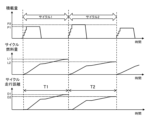
- the traveling cycle (hereinafter referred to as cycle) of the mine dump truck 101 includes a loading state (loading), a loading state (loading travel), a loading unloading state (soil dumping), and a loading state. It is roughly divided into four states of traveling with no load (running without load). An example of the state determination method will be described.
- the predetermined value P1 is a threshold value for determining whether or not the vehicle is loaded, and the loaded state is determined at the timing (T1) when the load exceeds the predetermined value P1 while the vehicle is stopped.
- a productivity index for example, a transport amount [T/L] per liter of fuel
- operation data is aggregated for each state for abnormality determination.
- one cycle is defined as one load from one load to the next load. May start the cycle.
- FIG. 4 is a diagram showing an example of aggregated operation data of the mine dump 101.
- the load calculated by the load calculation device is shown in the upper row
- the cycle fuel obtained by integrating the engine injection amount for each cycle is shown in the middle row
- the cycle traveling distance obtained by integrating the vehicle speed for each cycle is shown in the lower row.
- the load of cycle 1 is P1
- the load of cycle 2 is P2
- the fuel amount of cycle 1 is L1
- the fuel amount of cycle 2 is L2
- the travel distance of cycle 1 is D1
- the travel distance of cycle 2 is D2
- the running time of cycle 1 is T1
- the running time of cycle 2 is T2.
- the productivity index [T/L] for cycle 1 is obtained by P1/L1
- the productivity index for cycle 2 is obtained by P2/L2.
- productivity index [T/L] varies greatly depending on the travel route (especially the length of the uphill road), even if the travel distance is the same. (acceleration/deceleration), road surface roughness, and other factors. Therefore, simply calculating the productivity index [T/L] for each cycle makes it difficult to manage productivity and obtain knowledge leading to maintenance and improvement. Therefore, in this embodiment, in addition to the productivity index [T/L], productivity is accurately managed and maintained by calculating the state-by-state efficiency described later.
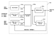
- FIG. 5 is a diagram showing an example of a functional block diagram of the processing device 202.
- the processing device 202 has a state determination section 202a, an input energy calculation section 202b, a consumption energy calculation section 202c, a state-by-state efficiency calculation section 202d, an abnormality determination section 202e, and a vehicle model calibration section 202f.
- the processing unit 202 is composed of a controller having an arithmetic processing function, an input/output interface for inputting/outputting signals with external devices, and the like. come true.
- the state determination unit 202a determines the state of the mine dump truck 101 based on the vehicle speed and load amount by the method described in FIG.
- the input signal to the state determination unit 202a varies depending on the state of the mine dump 101 to be determined. For example, in order to determine the operating state of the trolley, it is necessary to input the trolley voltage or the like.
- the energy consumption calculation unit 202c calculates the energy consumption [kW/h] from the vehicle speed, altitude, and load capacity by a method described later.
- the state-by-state efficiency calculation unit 202d calculates the state-by-state efficiency in a predetermined state (cycle, empty operation, loaded operation, etc.).
- the vehicle model calibration unit 202f adjusts the road surface coefficient and auxiliary power (energy consumption) so that the state-by-state efficiency falls within a predetermined range when the abnormality determination unit 202e does not determine that the load sensor 101a or the power train system is abnormal. parameters of the vehicle model used for the calculation) are corrected. With this configuration, it is possible to realize a robust abnormality determination against changes in the road surface coefficient and auxiliary power that are greatly influenced by the mine environment (weather, etc.). By inspecting or calibrating the sensor 101a, the productivity index for each cycle can be calculated accurately.
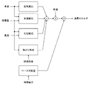
- FIG. 6 is a diagram showing an example of a method of calculating energy consumption using a vehicle model.
- Energy consumption during vehicle running is calculated by multiplying the sum of air resistance, acceleration resistance, slope resistance, and rolling resistance by vehicle speed, and adding the base consumption required for auxiliary equipment such as engine idling, cooling fans, and cabin air conditioning. obtained by Here, by obtaining the vehicle speed, load capacity, and altitude from the vehicle operation data, it is possible to calculate the energy consumption according to the actual driving conditions.
- Air resistance also depends on air density, which changes according to the weather, but since the impact of air resistance is small compared to rolling resistance and base consumption, the value determined here is based only on vehicle speed.
- the slope resistance is obtained from the total vehicle weight, which is the weight of the vehicle plus the load capacity, and the slope of the road surface.
- the road gradient is obtained from the change in altitude over time, but if the vehicle body is provided with an inclination angle sensor, it may be obtained from the inclination angle of the vehicle body.
- step S701 If it is determined YES in step S701 (there is no abnormality in the load sensor 101a or the powertrain system), the state-by-state efficiency (steady-state operation efficiency) in the operating region in which the efficiency of the powertrain system is substantially constant is calculated (step S702).
- Efficiency during steady-state operation is the state-by-state efficiency calculated when the vehicle is running at a constant speed (with almost no acceleration resistance).
- the state-specific efficiency is used to correct the road surface coefficient for the entire mine area, but it is also possible to determine a predetermined route or predetermined section using GPS coordinates, and correct the road surface coefficient for each determined route or section.
- step S703 it is determined whether or not the efficiency during steady operation is smaller than a predetermined value R1 (minimum efficiency assumed during steady operation) (step S703). If it is determined as YES in step S703 (the steady-state driving efficiency is smaller than the predetermined value R1), the road surface coefficient is corrected to increase (step S704), and the flow ends.
- a predetermined value R1 minimum efficiency assumed during steady operation
- FIG. 8 is a flowchart showing an example of processing executed when the vehicle model calibration unit 202f corrects the auxiliary power. Each step will be described in order below.
- step S801 If it is determined YES in step S801 (there is no abnormality in the load sensor 101a or the powertrain system), the state-by-state efficiency during idle operation (idle operation efficiency) in which the power consumption of the auxiliary equipment is dominant is calculated (step S802).
- step S803 it is determined whether or not the efficiency during idle operation is smaller than a predetermined value I1 (minimum efficiency assumed during idle operation) (step S803). If it is determined YES in step S803 (the efficiency during idling is smaller than the predetermined value I1), the auxiliary electric power is corrected to the increasing side (step S804), and the flow ends.
- a predetermined value I1 minimum efficiency assumed during idle operation
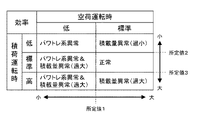
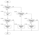
- step S1101 If it is determined YES in step S1101 (the efficiency during empty operation is smaller than the predetermined value 1), the equipment maintenance staff 304 is notified of an abnormality in the power train system (step S1102). At this time, the operation planner 301 may be notified to refrain from using the vehicle.
- step S1103 it is determined whether or not the state-specific efficiency during loaded operation (efficiency during loaded operation) is equal to or greater than a predetermined value 2 (step S1103). If the determination in step S1103 is NO (the efficiency during loaded operation is smaller than the predetermined value 2), the flow ends.
- step S1101 If it is determined NO in step S1101 (the efficiency during empty operation is equal to or greater than the predetermined value 1), it is determined whether the efficiency during loaded operation is smaller than a predetermined value 2 (step S1105).
- step S1105 the efficiency during loaded operation is equal to or less than the predetermined value 2
- step S1107 it is determined whether the efficiency during loaded operation is equal to or greater than a predetermined value 3 (step S1107). If it is determined NO in step S1107 (the efficiency during loaded operation is smaller than the predetermined value 3), the flow ends.
- step S1107 If it is determined YES in step S1107 (the efficiency during load operation is equal to or greater than the predetermined value of 3), it is determined that the load amount is detected to be excessively large due to an abnormality in the load amount sensor 101a.
- the equipment maintenance staff 304 is notified to calibrate the load sensor 101a, or the mine dump truck 101 is remotely instructed to calibrate the load sensor 101a. (Step S1108), the flow ends.
- the load sensor 101a can be calibrated at an appropriate timing, and by excluding the productivity index of the cycle in which the load is detected to be too small or too large from the tallying process, It is possible to prevent aggregation and management of productivity indicators based on inaccurate load capacity.
- FIG. 12 is a diagram showing a display example of efficiency during empty operation and efficiency during loaded operation aggregated by dump truck.
- the efficiency during empty operation and the efficiency during loaded operation for a predetermined period are displayed in a box chart for each mine dump.
- Tr5, Tr21, and Tr1 are determined to have a powertrain system abnormality because the efficiency during empty operation is smaller than the predetermined value 1. Furthermore, since the efficiency during loaded operation of Tr1 is equal to or greater than the predetermined value 2, it is also determined that the load sensor 101a is abnormal (excessive detection). In the Tr6 machine, the efficiency during empty operation is equal to or higher than the predetermined value 1 and the efficiency during loaded operation is smaller than the predetermined value 2, so it is determined that the load amount sensor 101a is abnormal (underdetection). In the Tr3 machine, since the efficiency during loaded operation is equal to or higher than the predetermined value 3, it is determined that the load amount sensor 101a is abnormal (underdetection). As shown in FIG.
- a mine management system 200 that manages a mine dump truck 101 operating in a mine includes a processing device 202 that calculates and aggregates the productivity index of the mine dump truck 101 .
- the energy consumption of the mine dump truck 101 is calculated based on the vehicle speed, the road surface gradient, and the load capacity, and the input energy of the mine dump truck 101 is calculated based on at least one of the fuel injection amount of the mine dump truck 101, the trolley power, and the battery power. Then, based on the consumed energy and the input energy, it is determined whether there is an abnormality in the load sensor 101a of the mine dump truck 101 or in the power train system.
- this embodiment configured as described above, it is possible to separately detect an abnormality in the power train system (power train system) of the mine dump truck 101 and the load sensor 101a.
- the productivity of the mine can be maintained and improved by performing maintenance/replacement of the power train system or by reducing the operation of the mine dump truck. can.
- the productivity of the mine can be accurately managed by calibrating the load sensor 101a.
- the processing device 202 in this embodiment controls the parameters (auxiliary equipment power).
- auxiliary equipment power controls the parameters (auxiliary equipment power).
- the processing device 202 in the present embodiment has the state-by-state efficiency when the mine dump truck 101 is in an empty operation that is lower than the first predetermined value (predetermined value 1) and the state-by-state efficiency when the mine dump truck 101 is in a loaded operation. is a second predetermined value (predetermined value 2) or more, or the state-specific efficiency during unloaded operation is a first predetermined value (first predetermined value) or more, and the state-specific efficiency during laden operation When the efficiency is out of a predetermined range (predetermined value 2 to predetermined value 3), it is determined that the load sensor 101a is abnormal. As a result, an abnormality of the load amount sensor 101a can be detected based on the state-by-state efficiency of the mine dump truck 101 during empty operation and loaded operation.
- the processing device 202 in this embodiment determines that the load sensor 101a is abnormal, it determines that the load sensor 101a needs to be calibrated. As a result, the load sensor 101a can be calibrated in a timely manner.
- the processing device 202 in this embodiment excludes the productivity index calculated while the load sensor 101a is determined to be abnormal from the counting process. As a result, it is possible to prevent aggregation and management of the productivity index based on an inaccurate load amount.
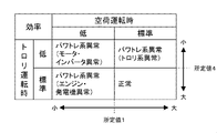
- the efficiency during no-load operation when the efficiency during no-load operation is smaller than a predetermined value 1 (minimum efficiency assumed during no-load operation), it is determined that the efficiency during no-load operation is low.
- a predetermined value 1 minimum efficiency assumed during no-load operation
- a predetermined value 4 minimum efficiency assumed during trolley operation
- the efficiency during trolley operation is low. is the standard. If the efficiency is low during empty-load operation, it is determined that there is an abnormality in the motor/inverter when the efficiency is low during trolley operation, and it is determined that the engine/generating system is abnormal when the efficiency during trolley operation is normal.
- FIG. 14 is a flowchart showing an example of processing executed by the abnormality determination unit 202e when identifying an abnormality in the powertrain system. Each step will be described in order below.
- step S1401 efficiency during empty operation is smaller than predetermined value 1
- step S1402 efficiency during trolley operation
- step S1402 If it is determined YES (the trolley efficiency is smaller than the predetermined value 4) in step S1402, the equipment maintenance staff 304 is notified of the motor/inverter abnormality (step S1403), and the flow ends. Since more fuel and trolley power are consumed than usual in this abnormal state, for example, the operation planner 301 may be notified of request information to reduce the frequency of use of the vehicle or to shorten the travel distance.
- step S1405 If it is determined YES (the trolley efficiency is smaller than the predetermined value 4) in step S1405, an abnormality in the trolley system is notified to the equipment maintenance personnel 304 (step S1406), and the flow ends. Since everything other than the trolley system is normal at the time of this abnormality, the decrease in productivity can be minimized by assigning the relevant vehicle to a route that does not use the trolley for the operation planner 301 .
- FIG. 15 is a diagram showing a display example of the efficiency during empty operation and the efficiency during trolley operation aggregated for each mine dump in a predetermined period.
- the efficiency during empty operation and the efficiency during loaded operation for a predetermined period are displayed in a box chart for each mine dump. Abnormality determination is performed by the method described with reference to FIGS.
- the productivity of the mine can be maintained by taking appropriate countermeasures against the faulty part. becomes possible.
- FIG. 16 A mine management system according to the third embodiment of the present invention will be explained using FIGS. 16 and 17.
- FIG. it is assumed that an abnormality of the load amount sensor 101a is not detected by the method described in the first embodiment.
- the processing device 202 first aggregates the cycle efficiencies calculated for each cycle for each route, and determines whether or not the aggregate representative value (for example, median value or average value) is lower than a predetermined value R (step S1601).
- the predetermined value R the minimum value of the cycle efficiency assumed for the corresponding route may be set, or the minimum value of the cycle efficiency assumed for the representative route may be set.
- step S1601 If it is determined in step S1601 that the total representative value is lower than the predetermined value R (YES), information (route ID) for identifying maintenance candidate routes is displayed on the display terminal device 203 (step S1602). As a result, the road surface maintenance staff 303 can perform maintenance on the route, and the operation planner 301 can review the operation plan so as to reduce the number of trips on the route.
- step S1601 If it is determined in step S1601 that the total representative value is equal to or greater than the predetermined value R (NO), or following step S1602, the cycle efficiency is totaled for each driver, and whether the total representative value is smaller than the predetermined value D (step S1603).
- the predetermined value D the minimum value of the cycle efficiency assumed in advance may be set.
- step S1603 If it is determined in step S1603 that the total representative value is lower than the predetermined value D (YES), the information (driver ID) for identifying the driver whose cycle efficiency is lower than the predetermined value D is displayed on the display terminal device 203. (Step S1604). This enables the operator instructor 302 to provide driving instruction to the driver.
- step S1603 If it is determined in step S1603 that the total representative value is equal to or greater than the predetermined value D (NO), or following step S1604, the cycle efficiency is totaled for each mine dump, and whether the total representative value is lower than the predetermined value V It is determined whether or not (step S1605). As the predetermined value V, the minimum value of the cycle efficiency assumed in advance may be set. If it is determined NO (the total representative value is equal to or greater than the predetermined value V) in step S1605, the flow ends.
- step S1605 determines YES (aggregation representative value is smaller than predetermined value V)
- information for identifying mine dump whose cycle efficiency is lower than predetermined value V is displayed on display terminal device 203. (step S1606) and the flow ends. This enables the equipment maintenance staff 304 to perform maintenance on the mine dump.
- FIG. 17 is a diagram showing a display example of cycle efficiency aggregated by route, by driver, and by mine dump.
- Cycle efficiencies calculated over a predetermined period e.g. one week
- route, driver, or mine dump are aggregated and displayed in ascending order of the median value, so that the routes, drivers, or mine dumps with low cycle efficiencies are displayed. 101 can be easily identified.
- the displayed aggregated results can be changed arbitrarily, and for example, only those with a small median value may be displayed.
- the thresholds predetermined values R, D, V
- the display can be arbitrarily changed, not only according to the user's designation, but also at preset timing, each time a problem occurs, or a combination thereof.
- the order of display by route, by driver, and by mine dump can be arbitrarily changed, and it is also possible to display only desired objects or to display them collectively.
- the notification history and analysis results (improvements/problems) in comparison with the history may be displayed together.
- the mode of notification is not limited to any form, such as e-mail to a smart phone or voice, as long as the person to be notified can confirm it. As a result, it is possible to quickly remove factors that reduce productivity.
- the processing device 202 in this embodiment aggregates the state-specific efficiencies for each route along which the mine dump truck travels, and determines that there is an abnormality in the road surface of the route where the aggregated representative value of the state-specific efficiencies is less than a predetermined value R. do. Further, the processing device 202 in this embodiment aggregates the state-by-state efficiency for each driver who drives the mine dump truck 101, and if the aggregated representative value of the state-by-state efficiency is less than a predetermined value D, there is a problem in the driving of the driver. I judge. In addition, the processing apparatus in this embodiment aggregates the state-by-state efficiency for each mine dump truck 101, and determines that the mine dump truck 101 for which the total representative value of the state-by-state efficiency falls below a predetermined value R is abnormal.
- the present invention is not limited to the above-described embodiments, and includes various modifications.
- the above embodiments have been described in detail for easy understanding of the present invention, and are not necessarily limited to those having all the described configurations. It is also possible to add part of the configuration of another embodiment to the configuration of one embodiment, or to delete part of the configuration of one embodiment or replace it with part of another embodiment. It is possible.
Landscapes
- Engineering & Computer Science (AREA)
- Business, Economics & Management (AREA)
- Physics & Mathematics (AREA)
- Human Resources & Organizations (AREA)
- General Physics & Mathematics (AREA)
- Automation & Control Theory (AREA)
- Strategic Management (AREA)
- Economics (AREA)
- Marketing (AREA)
- Tourism & Hospitality (AREA)
- Theoretical Computer Science (AREA)
- General Business, Economics & Management (AREA)
- Transportation (AREA)
- Mechanical Engineering (AREA)
- Primary Health Care (AREA)
- General Health & Medical Sciences (AREA)
- Health & Medical Sciences (AREA)
- Human Computer Interaction (AREA)
- Entrepreneurship & Innovation (AREA)
- Quality & Reliability (AREA)
- Mining & Mineral Resources (AREA)
- Development Economics (AREA)
- Life Sciences & Earth Sciences (AREA)
- Agronomy & Crop Science (AREA)
- Animal Husbandry (AREA)
- Marine Sciences & Fisheries (AREA)
- Educational Administration (AREA)
- Operations Research (AREA)
- Mathematical Physics (AREA)
- Game Theory and Decision Science (AREA)
- Traffic Control Systems (AREA)
- Management, Administration, Business Operations System, And Electronic Commerce (AREA)
- Electric Propulsion And Braking For Vehicles (AREA)
- Operation Control Of Excavators (AREA)
Priority Applications (6)
| Application Number | Priority Date | Filing Date | Title |
|---|---|---|---|
| CN202280019490.2A CN116964650A (zh) | 2021-08-05 | 2022-04-11 | 矿山管理系统 |
| AU2022324820A AU2022324820B2 (en) | 2021-08-05 | 2022-04-11 | Mine management system |
| JP2023539648A JP7515026B2 (ja) | 2021-08-05 | 2022-04-11 | 鉱山管理システム |
| CA3211298A CA3211298A1 (en) | 2021-08-05 | 2022-04-11 | Mine management system |
| US18/280,776 US12444245B2 (en) | 2021-08-05 | 2022-04-11 | Mine management system |
| EP22852610.9A EP4290492A4 (en) | 2021-08-05 | 2022-04-11 | MINE MANAGEMENT SYSTEM |
Applications Claiming Priority (2)
| Application Number | Priority Date | Filing Date | Title |
|---|---|---|---|
| JP2021128964 | 2021-08-05 | ||
| JP2021-128964 | 2021-08-05 |
Publications (1)
| Publication Number | Publication Date |
|---|---|
| WO2023013181A1 true WO2023013181A1 (ja) | 2023-02-09 |
Family
ID=85155613
Family Applications (1)
| Application Number | Title | Priority Date | Filing Date |
|---|---|---|---|
| PCT/JP2022/017536 Ceased WO2023013181A1 (ja) | 2021-08-05 | 2022-04-11 | 鉱山管理システム |
Country Status (7)
| Country | Link |
|---|---|
| US (1) | US12444245B2 (https=) |
| EP (1) | EP4290492A4 (https=) |
| JP (1) | JP7515026B2 (https=) |
| CN (1) | CN116964650A (https=) |
| AU (1) | AU2022324820B2 (https=) |
| CA (1) | CA3211298A1 (https=) |
| WO (1) | WO2023013181A1 (https=) |
Families Citing this family (1)
| Publication number | Priority date | Publication date | Assignee | Title |
|---|---|---|---|---|
| JP2025151123A (ja) * | 2024-03-27 | 2025-10-09 | 川田工業株式会社 | 作業管理装置、作業管理システム、及び作業管理方法 |
Citations (4)
| Publication number | Priority date | Publication date | Assignee | Title |
|---|---|---|---|---|
| JPH06510418A (ja) * | 1991-09-03 | 1994-11-17 | ワグナー マイニング アンド コンストラクション イクイップメント カンパニー | 可変速度ac電気駆動車両 |
| JP2008133798A (ja) * | 2006-11-29 | 2008-06-12 | Hitachi Ltd | 車両のエネルギ伝達診断装置 |
| WO2015029229A1 (ja) | 2013-08-30 | 2015-03-05 | 株式会社小松製作所 | 鉱山機械の管理システム及び管理方法 |
| WO2017081912A1 (ja) * | 2015-11-11 | 2017-05-18 | 日立建機株式会社 | 運搬車両 |
Family Cites Families (20)
| Publication number | Priority date | Publication date | Assignee | Title |
|---|---|---|---|---|
| US7571683B2 (en) * | 2001-03-27 | 2009-08-11 | General Electric Company | Electrical energy capture system with circuitry for blocking flow of undesirable electrical currents therein |
| JP4186723B2 (ja) * | 2003-06-20 | 2008-11-26 | トヨタ自動車株式会社 | エネルギー管理装置およびエネルギー管理方法 |
| US8190335B2 (en) * | 2008-02-04 | 2012-05-29 | Caterpillar Inc. | Performance management system for multi-machine worksite |
| US8543287B2 (en) * | 2009-09-25 | 2013-09-24 | Cross Chasm Technologies Inc. | System, method and computer program for simulating vehicle energy use |
| JP2012031824A (ja) * | 2010-08-02 | 2012-02-16 | Fuji Heavy Ind Ltd | 車両の燃料消費率評価装置 |
| JP5596661B2 (ja) * | 2011-11-11 | 2014-09-24 | 株式会社小松製作所 | 鉱山機械の管理システム及び鉱山機械の管理システムの管理方法 |
| CA2900352C (en) * | 2013-03-15 | 2023-02-14 | Crown Equipment Corporation | Normalizing performance data across industrial vehicles |
| CA2848835C (en) * | 2013-08-30 | 2016-10-25 | Motohide Sugihara | Management system and management method of mining machine |
| JP6329904B2 (ja) * | 2014-03-12 | 2018-05-23 | 株式会社小松製作所 | 運搬車両の運転解析装置および運転解析方法 |
| US9600541B2 (en) * | 2014-05-02 | 2017-03-21 | Kookmin University Industry Academy Corporation Foundation | Method of processing and analysing vehicle driving big data and system thereof |
| WO2016074600A1 (zh) * | 2014-11-11 | 2016-05-19 | 冯春魁 | 车辆运行监控、监视、数据处理、超载监控的方法及系统 |
| EP3245340A1 (en) * | 2015-01-15 | 2017-11-22 | Modustri LLC | Configurable monitor and parts management system |
| JP6958170B2 (ja) * | 2017-09-22 | 2021-11-02 | 株式会社デンソー | 電流センサの診断装置 |
| JP6968026B2 (ja) * | 2018-04-27 | 2021-11-17 | 株式会社ブリヂストン | タイヤ状態検出装置 |
| CN108806021B (zh) * | 2018-06-12 | 2020-11-06 | 重庆大学 | 基于物理模型和道路特征参数的电动汽车目标路段能耗预测方法 |
| IT201800008155A1 (it) * | 2018-08-22 | 2020-02-22 | Iveco Spa | Metodo e sistema di monitoraggio e di determinazione di una causa di extra-consumo di combustibile |
| JP7215175B2 (ja) * | 2019-01-09 | 2023-01-31 | 住友電気工業株式会社 | センサ異常検出装置、分散型電源システム、及びセンサ異常判定方法 |
| JP7415364B2 (ja) * | 2019-08-02 | 2024-01-17 | 株式会社オートネットワーク技術研究所 | 車載中継装置、コンピュータプログラム及び故障判定方法 |
| US11892836B2 (en) * | 2020-01-27 | 2024-02-06 | Liebherr Mining Equipment Newport News Co. | System for controlling a plurality of autonomous vehicles on a mine site |
| CN112907173B (zh) * | 2021-02-20 | 2024-04-12 | 三一重型装备有限公司 | 矿车运行工况的获取方法及装置 |
-
2022
- 2022-04-11 AU AU2022324820A patent/AU2022324820B2/en active Active
- 2022-04-11 US US18/280,776 patent/US12444245B2/en active Active
- 2022-04-11 WO PCT/JP2022/017536 patent/WO2023013181A1/ja not_active Ceased
- 2022-04-11 JP JP2023539648A patent/JP7515026B2/ja active Active
- 2022-04-11 EP EP22852610.9A patent/EP4290492A4/en active Pending
- 2022-04-11 CN CN202280019490.2A patent/CN116964650A/zh active Pending
- 2022-04-11 CA CA3211298A patent/CA3211298A1/en active Pending
Patent Citations (4)
| Publication number | Priority date | Publication date | Assignee | Title |
|---|---|---|---|---|
| JPH06510418A (ja) * | 1991-09-03 | 1994-11-17 | ワグナー マイニング アンド コンストラクション イクイップメント カンパニー | 可変速度ac電気駆動車両 |
| JP2008133798A (ja) * | 2006-11-29 | 2008-06-12 | Hitachi Ltd | 車両のエネルギ伝達診断装置 |
| WO2015029229A1 (ja) | 2013-08-30 | 2015-03-05 | 株式会社小松製作所 | 鉱山機械の管理システム及び管理方法 |
| WO2017081912A1 (ja) * | 2015-11-11 | 2017-05-18 | 日立建機株式会社 | 運搬車両 |
Non-Patent Citations (1)
| Title |
|---|
| See also references of EP4290492A4 |
Also Published As
| Publication number | Publication date |
|---|---|
| CN116964650A (zh) | 2023-10-27 |
| EP4290492A1 (en) | 2023-12-13 |
| US20240304038A1 (en) | 2024-09-12 |
| AU2022324820A1 (en) | 2023-09-21 |
| AU2022324820B2 (en) | 2025-09-04 |
| EP4290492A4 (en) | 2025-02-19 |
| JP7515026B2 (ja) | 2024-07-11 |
| US12444245B2 (en) | 2025-10-14 |
| JPWO2023013181A1 (https=) | 2023-02-09 |
| CA3211298A1 (en) | 2023-02-09 |
Similar Documents
| Publication | Publication Date | Title |
|---|---|---|
| JP6502294B2 (ja) | 電気トラックの走行ルート選定システム、電気トラックの走行ルート選定方法 | |
| US9937936B2 (en) | System and method for monitoring coupler fatigue | |
| JP6013739B2 (ja) | 運搬車両運行支援システム及び運搬車両運行支援方法 | |
| CN115081669A (zh) | 电耗预测装置 | |
| CN115427256A (zh) | 用于监测电池单元老化的方法 | |
| JP7515026B2 (ja) | 鉱山管理システム | |
| JP6626310B2 (ja) | 車両消費の監視システムおよび方法 | |
| JP6597752B2 (ja) | 車両用表示装置 | |
| JP5240244B2 (ja) | バッテリ異常警告装置 | |
| JP6311142B2 (ja) | ハイブリッド車両の制御システム及びハイブリッド車両の制御方法 | |
| JP6936827B2 (ja) | 電気トラックの走行ルート選定システム、電気トラックの走行ルート選定方法 | |
| US11734965B2 (en) | Method and system of calculating distance to empty of each vehicle drive mode | |
| EP3979167A1 (en) | Information processing method and information processing system | |
| WO2021079582A1 (ja) | 情報処理方法、情報処理装置、及び情報処理プログラム | |
| JP2023121569A (ja) | オイル管理システム | |
| JP2018025401A (ja) | 電気トラックの走行ルート選定システム、電気トラックの走行ルート選定方法 | |
| KR102896304B1 (ko) | 배터리 주행거리 산출 장치 및 방법 | |
| JP2024055213A (ja) | 運搬車両の管理システム | |
| EP4227141A1 (en) | A method for determining ageing of a fuel cell system | |
| US12481004B2 (en) | Systems and methods for monitoring a state of health of a battery system of an electric vehicle | |
| US20250256589A1 (en) | Vertical range estimation for tired machine | |
| WO2024201651A1 (ja) | 情報処理装置、情報処理方法および非一時的なコンピュータ可読記録媒体 | |
| CN115071498A (zh) | 电动矿卡载运能力自诊断系统及其耗能估算方法 | |
| US20260054602A1 (en) | Method and control arrangement for setting a remaining distance to empty parameter in an electric vehicle | |
| JP2019167029A (ja) | 運搬車両、走行速度提示装置 |
Legal Events
| Date | Code | Title | Description |
|---|---|---|---|
| 121 | Ep: the epo has been informed by wipo that ep was designated in this application |
Ref document number: 22852610 Country of ref document: EP Kind code of ref document: A1 |
|
| WWE | Wipo information: entry into national phase |
Ref document number: 2023539648 Country of ref document: JP |
|
| WWE | Wipo information: entry into national phase |
Ref document number: 202280019490.2 Country of ref document: CN |
|
| WWE | Wipo information: entry into national phase |
Ref document number: 18280776 Country of ref document: US Ref document number: 2022324820 Country of ref document: AU Ref document number: 3211298 Country of ref document: CA |
|
| ENP | Entry into the national phase |
Ref document number: 2022852610 Country of ref document: EP Effective date: 20230906 |
|
| ENP | Entry into the national phase |
Ref document number: 2022324820 Country of ref document: AU Date of ref document: 20220411 Kind code of ref document: A |
|
| NENP | Non-entry into the national phase |
Ref country code: DE |
|
| WWG | Wipo information: grant in national office |
Ref document number: 18280776 Country of ref document: US |