WO2023008486A1 - 車両の制動制御装置 - Google Patents
車両の制動制御装置 Download PDFInfo
- Publication number
- WO2023008486A1 WO2023008486A1 PCT/JP2022/028953 JP2022028953W WO2023008486A1 WO 2023008486 A1 WO2023008486 A1 WO 2023008486A1 JP 2022028953 W JP2022028953 W JP 2022028953W WO 2023008486 A1 WO2023008486 A1 WO 2023008486A1
- Authority
- WO
- WIPO (PCT)
- Prior art keywords
- pressure
- master
- servo
- bottoming
- chamber
- Prior art date
- Legal status (The legal status is an assumption and is not a legal conclusion. Google has not performed a legal analysis and makes no representation as to the accuracy of the status listed.)
- Ceased
Links
Images



Classifications
-
- B—PERFORMING OPERATIONS; TRANSPORTING
- B60—VEHICLES IN GENERAL
- B60T—VEHICLE BRAKE CONTROL SYSTEMS OR PARTS THEREOF; BRAKE CONTROL SYSTEMS OR PARTS THEREOF, IN GENERAL; ARRANGEMENT OF BRAKING ELEMENTS ON VEHICLES IN GENERAL; PORTABLE DEVICES FOR PREVENTING UNWANTED MOVEMENT OF VEHICLES; VEHICLE MODIFICATIONS TO FACILITATE COOLING OF BRAKES
- B60T13/00—Transmitting braking action from initiating means to ultimate brake actuator with power assistance or drive; Brake systems incorporating such transmitting means, e.g. air-pressure brake systems
- B60T13/10—Transmitting braking action from initiating means to ultimate brake actuator with power assistance or drive; Brake systems incorporating such transmitting means, e.g. air-pressure brake systems with fluid assistance, drive, or release
- B60T13/12—Transmitting braking action from initiating means to ultimate brake actuator with power assistance or drive; Brake systems incorporating such transmitting means, e.g. air-pressure brake systems with fluid assistance, drive, or release the fluid being liquid
- B60T13/14—Transmitting braking action from initiating means to ultimate brake actuator with power assistance or drive; Brake systems incorporating such transmitting means, e.g. air-pressure brake systems with fluid assistance, drive, or release the fluid being liquid using accumulators or reservoirs fed by pumps
- B60T13/148—Arrangements for pressure supply
-
- B—PERFORMING OPERATIONS; TRANSPORTING
- B60—VEHICLES IN GENERAL
- B60T—VEHICLE BRAKE CONTROL SYSTEMS OR PARTS THEREOF; BRAKE CONTROL SYSTEMS OR PARTS THEREOF, IN GENERAL; ARRANGEMENT OF BRAKING ELEMENTS ON VEHICLES IN GENERAL; PORTABLE DEVICES FOR PREVENTING UNWANTED MOVEMENT OF VEHICLES; VEHICLE MODIFICATIONS TO FACILITATE COOLING OF BRAKES
- B60T13/00—Transmitting braking action from initiating means to ultimate brake actuator with power assistance or drive; Brake systems incorporating such transmitting means, e.g. air-pressure brake systems
- B60T13/10—Transmitting braking action from initiating means to ultimate brake actuator with power assistance or drive; Brake systems incorporating such transmitting means, e.g. air-pressure brake systems with fluid assistance, drive, or release
- B60T13/12—Transmitting braking action from initiating means to ultimate brake actuator with power assistance or drive; Brake systems incorporating such transmitting means, e.g. air-pressure brake systems with fluid assistance, drive, or release the fluid being liquid
- B60T13/14—Transmitting braking action from initiating means to ultimate brake actuator with power assistance or drive; Brake systems incorporating such transmitting means, e.g. air-pressure brake systems with fluid assistance, drive, or release the fluid being liquid using accumulators or reservoirs fed by pumps
- B60T13/142—Systems with master cylinder
- B60T13/145—Master cylinder integrated or hydraulically coupled with booster
-
- B—PERFORMING OPERATIONS; TRANSPORTING
- B60—VEHICLES IN GENERAL
- B60T—VEHICLE BRAKE CONTROL SYSTEMS OR PARTS THEREOF; BRAKE CONTROL SYSTEMS OR PARTS THEREOF, IN GENERAL; ARRANGEMENT OF BRAKING ELEMENTS ON VEHICLES IN GENERAL; PORTABLE DEVICES FOR PREVENTING UNWANTED MOVEMENT OF VEHICLES; VEHICLE MODIFICATIONS TO FACILITATE COOLING OF BRAKES
- B60T13/00—Transmitting braking action from initiating means to ultimate brake actuator with power assistance or drive; Brake systems incorporating such transmitting means, e.g. air-pressure brake systems
- B60T13/10—Transmitting braking action from initiating means to ultimate brake actuator with power assistance or drive; Brake systems incorporating such transmitting means, e.g. air-pressure brake systems with fluid assistance, drive, or release
- B60T13/12—Transmitting braking action from initiating means to ultimate brake actuator with power assistance or drive; Brake systems incorporating such transmitting means, e.g. air-pressure brake systems with fluid assistance, drive, or release the fluid being liquid
- B60T13/14—Transmitting braking action from initiating means to ultimate brake actuator with power assistance or drive; Brake systems incorporating such transmitting means, e.g. air-pressure brake systems with fluid assistance, drive, or release the fluid being liquid using accumulators or reservoirs fed by pumps
- B60T13/142—Systems with master cylinder
- B60T13/145—Master cylinder integrated or hydraulically coupled with booster
- B60T13/146—Part of the system directly actuated by booster pressure
-
- B—PERFORMING OPERATIONS; TRANSPORTING
- B60—VEHICLES IN GENERAL
- B60T—VEHICLE BRAKE CONTROL SYSTEMS OR PARTS THEREOF; BRAKE CONTROL SYSTEMS OR PARTS THEREOF, IN GENERAL; ARRANGEMENT OF BRAKING ELEMENTS ON VEHICLES IN GENERAL; PORTABLE DEVICES FOR PREVENTING UNWANTED MOVEMENT OF VEHICLES; VEHICLE MODIFICATIONS TO FACILITATE COOLING OF BRAKES
- B60T13/00—Transmitting braking action from initiating means to ultimate brake actuator with power assistance or drive; Brake systems incorporating such transmitting means, e.g. air-pressure brake systems
- B60T13/10—Transmitting braking action from initiating means to ultimate brake actuator with power assistance or drive; Brake systems incorporating such transmitting means, e.g. air-pressure brake systems with fluid assistance, drive, or release
- B60T13/66—Electrical control in fluid-pressure brake systems
-
- B—PERFORMING OPERATIONS; TRANSPORTING
- B60—VEHICLES IN GENERAL
- B60T—VEHICLE BRAKE CONTROL SYSTEMS OR PARTS THEREOF; BRAKE CONTROL SYSTEMS OR PARTS THEREOF, IN GENERAL; ARRANGEMENT OF BRAKING ELEMENTS ON VEHICLES IN GENERAL; PORTABLE DEVICES FOR PREVENTING UNWANTED MOVEMENT OF VEHICLES; VEHICLE MODIFICATIONS TO FACILITATE COOLING OF BRAKES
- B60T13/00—Transmitting braking action from initiating means to ultimate brake actuator with power assistance or drive; Brake systems incorporating such transmitting means, e.g. air-pressure brake systems
- B60T13/10—Transmitting braking action from initiating means to ultimate brake actuator with power assistance or drive; Brake systems incorporating such transmitting means, e.g. air-pressure brake systems with fluid assistance, drive, or release
- B60T13/66—Electrical control in fluid-pressure brake systems
- B60T13/662—Electrical control in fluid-pressure brake systems characterised by specified functions of the control system components
-
- B—PERFORMING OPERATIONS; TRANSPORTING
- B60—VEHICLES IN GENERAL
- B60T—VEHICLE BRAKE CONTROL SYSTEMS OR PARTS THEREOF; BRAKE CONTROL SYSTEMS OR PARTS THEREOF, IN GENERAL; ARRANGEMENT OF BRAKING ELEMENTS ON VEHICLES IN GENERAL; PORTABLE DEVICES FOR PREVENTING UNWANTED MOVEMENT OF VEHICLES; VEHICLE MODIFICATIONS TO FACILITATE COOLING OF BRAKES
- B60T13/00—Transmitting braking action from initiating means to ultimate brake actuator with power assistance or drive; Brake systems incorporating such transmitting means, e.g. air-pressure brake systems
- B60T13/10—Transmitting braking action from initiating means to ultimate brake actuator with power assistance or drive; Brake systems incorporating such transmitting means, e.g. air-pressure brake systems with fluid assistance, drive, or release
- B60T13/66—Electrical control in fluid-pressure brake systems
- B60T13/68—Electrical control in fluid-pressure brake systems by electrically-controlled valves
- B60T13/686—Electrical control in fluid-pressure brake systems by electrically-controlled valves in hydraulic systems or parts thereof
-
- B—PERFORMING OPERATIONS; TRANSPORTING
- B60—VEHICLES IN GENERAL
- B60T—VEHICLE BRAKE CONTROL SYSTEMS OR PARTS THEREOF; BRAKE CONTROL SYSTEMS OR PARTS THEREOF, IN GENERAL; ARRANGEMENT OF BRAKING ELEMENTS ON VEHICLES IN GENERAL; PORTABLE DEVICES FOR PREVENTING UNWANTED MOVEMENT OF VEHICLES; VEHICLE MODIFICATIONS TO FACILITATE COOLING OF BRAKES
- B60T17/00—Component parts, details, or accessories of power brake systems not covered by groups B60T8/00, B60T13/00 or B60T15/00, or presenting other characteristic features
- B60T17/18—Safety devices; Monitoring
-
- B—PERFORMING OPERATIONS; TRANSPORTING
- B60—VEHICLES IN GENERAL
- B60T—VEHICLE BRAKE CONTROL SYSTEMS OR PARTS THEREOF; BRAKE CONTROL SYSTEMS OR PARTS THEREOF, IN GENERAL; ARRANGEMENT OF BRAKING ELEMENTS ON VEHICLES IN GENERAL; PORTABLE DEVICES FOR PREVENTING UNWANTED MOVEMENT OF VEHICLES; VEHICLE MODIFICATIONS TO FACILITATE COOLING OF BRAKES
- B60T17/00—Component parts, details, or accessories of power brake systems not covered by groups B60T8/00, B60T13/00 or B60T15/00, or presenting other characteristic features
- B60T17/18—Safety devices; Monitoring
- B60T17/22—Devices for monitoring or checking brake systems; Signal devices
-
- B—PERFORMING OPERATIONS; TRANSPORTING
- B60—VEHICLES IN GENERAL
- B60T—VEHICLE BRAKE CONTROL SYSTEMS OR PARTS THEREOF; BRAKE CONTROL SYSTEMS OR PARTS THEREOF, IN GENERAL; ARRANGEMENT OF BRAKING ELEMENTS ON VEHICLES IN GENERAL; PORTABLE DEVICES FOR PREVENTING UNWANTED MOVEMENT OF VEHICLES; VEHICLE MODIFICATIONS TO FACILITATE COOLING OF BRAKES
- B60T7/00—Brake-action initiating means
- B60T7/02—Brake-action initiating means for personal initiation
- B60T7/04—Brake-action initiating means for personal initiation foot actuated
- B60T7/042—Brake-action initiating means for personal initiation foot actuated by electrical means, e.g. using travel or force sensors
-
- B—PERFORMING OPERATIONS; TRANSPORTING
- B60—VEHICLES IN GENERAL
- B60T—VEHICLE BRAKE CONTROL SYSTEMS OR PARTS THEREOF; BRAKE CONTROL SYSTEMS OR PARTS THEREOF, IN GENERAL; ARRANGEMENT OF BRAKING ELEMENTS ON VEHICLES IN GENERAL; PORTABLE DEVICES FOR PREVENTING UNWANTED MOVEMENT OF VEHICLES; VEHICLE MODIFICATIONS TO FACILITATE COOLING OF BRAKES
- B60T8/00—Arrangements for adjusting wheel-braking force to meet varying vehicular or ground-surface conditions, e.g. limiting or varying distribution of braking force
- B60T8/17—Using electrical or electronic regulation means to control braking
-
- B—PERFORMING OPERATIONS; TRANSPORTING
- B60—VEHICLES IN GENERAL
- B60T—VEHICLE BRAKE CONTROL SYSTEMS OR PARTS THEREOF; BRAKE CONTROL SYSTEMS OR PARTS THEREOF, IN GENERAL; ARRANGEMENT OF BRAKING ELEMENTS ON VEHICLES IN GENERAL; PORTABLE DEVICES FOR PREVENTING UNWANTED MOVEMENT OF VEHICLES; VEHICLE MODIFICATIONS TO FACILITATE COOLING OF BRAKES
- B60T8/00—Arrangements for adjusting wheel-braking force to meet varying vehicular or ground-surface conditions, e.g. limiting or varying distribution of braking force
- B60T8/32—Arrangements for adjusting wheel-braking force to meet varying vehicular or ground-surface conditions, e.g. limiting or varying distribution of braking force responsive to a speed condition, e.g. acceleration or deceleration
- B60T8/34—Arrangements for adjusting wheel-braking force to meet varying vehicular or ground-surface conditions, e.g. limiting or varying distribution of braking force responsive to a speed condition, e.g. acceleration or deceleration having a fluid pressure regulator responsive to a speed condition
- B60T8/40—Arrangements for adjusting wheel-braking force to meet varying vehicular or ground-surface conditions, e.g. limiting or varying distribution of braking force responsive to a speed condition, e.g. acceleration or deceleration having a fluid pressure regulator responsive to a speed condition comprising an additional fluid circuit including fluid pressurising means for modifying the pressure of the braking fluid, e.g. including wheel driven pumps for detecting a speed condition, or pumps which are controlled by means independent of the braking system
Definitions
- the present disclosure relates to a vehicle braking control device.
- Patent Document 1 in a hydraulic brake system including a cylinder device having a front chamber in front of a pressurizing piston and a rear chamber behind the pressurizing piston, the presence or absence of fluid leakage in the brake system is determined based on the hydraulic pressure in the rear chamber. It is described that the Specifically, the state in which the value ⁇ P obtained by subtracting the actual rear hydraulic pressure from the target rear hydraulic pressure is greater than the first abnormality determination threshold value ⁇ Pth continues for the first abnormality determination time T1 or longer, and then the actual rear hydraulic pressure Ps increases. When it increases above the set gradient and the subtracted value ⁇ P becomes smaller than the restoration determination threshold value ⁇ p, it is determined that the pressurizing piston has bottomed due to leakage of hydraulic fluid from the front chamber.
- the state of master pistons 12c and 12d is determined based on the reaction hydraulic pressure detected by the reaction hydraulic pressure detector 25b and the master hydraulic pressure detected by the master hydraulic pressure detector Y. It is described that it is determined whether or not there is a state. Specifically, in Patent Document 2, when the stroke is less than a predetermined value (for example, a value corresponding to the bottoming stroke of the piston 13a2 of the stroke simulator 13a), the amount of increase in the stroke per unit time and the master Bottoming determination is performed based on the amount of increase in hydraulic pressure per unit time. On the other hand, when the stroke is equal to or greater than the predetermined value, the bottoming determination is performed based on the amount of increase per unit time of the reaction hydraulic pressure and the amount of increase per unit time of the master hydraulic pressure.
- a predetermined value for example, a value corresponding to the bottoming stroke of the piston 13a2 of the stroke simulator 13a
- the amount of increase in the stroke per unit time and the master Bottoming determination is performed based on the amount of increase in hydraulic pressure per
- Patent Document 1 the presence or absence of fluid leakage in the brake system is detected based on the difference between the control target (that is, target rear hydraulic pressure) and the control result (that is, actual rear hydraulic pressure).
- the stroke and the reaction hydraulic pressure correspond to the input at the brake pedal, so these state quantities are used to determine the control target in the hydraulic pressure control.
- the master hydraulic pressure is the result of pressure regulation control. Therefore, in Patent Document 2, similarly to Patent Document 1, the occurrence of bottoming (that is, the bottoming state) is determined based on the relationship between the control target and the control result.
- a slope ratio which is the amount of increase per unit time in the master hydraulic pressure with respect to the amount of increase in the reaction hydraulic pressure per unit time, is calculated. be done. Therefore, it is desired to quickly and reliably determine the bottoming state based on simple processing.
- An object of the present invention is to provide a braking control device for a vehicle that can quickly and reliably determine the bottoming of the master piston.
- the braking control device SC includes "a master cylinder (CM) having a master chamber (Rm) partitioned by a master piston (NP, NS)" and “for the master piston (NP, NS), A servo chamber (Ru) located on the opposite side of the master chamber (Rm) is provided.
- a servo pressure (Pu) is supplied to the servo chamber (Ru), and a master pressure (Pm ), and a first pressure regulating unit (YA) that generates
- the first pressure regulating unit (YA) acquires the master pressure (Pm) and the servo pressure (Pu), and based on a comparison between the master pressure (Pm) and the servo pressure (Pu), Bottoming of the master piston (NP, NS) is determined.
- the first pressure regulating unit (YA) performs the comparison based on the pressure receiving area (ru) of the servo chamber (Ru) and the pressure receiving area (rm) of the master chamber (Rm).
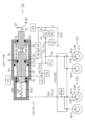
- FIG. 1 is a schematic diagram for explaining an entire vehicle JV equipped with a braking control device SC;
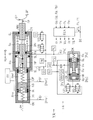
- FIG. 4 is a schematic diagram for explaining a first configuration example of the first pressure regulating unit YA;
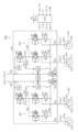
- FIG. 4 is a schematic diagram for explaining a configuration example of a second pressure regulating unit YB;
- FIG. 4 is a flow chart for explaining pressure regulation control;
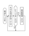
- FIG. 10 is a flow chart for explaining bottoming processing;
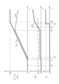
- FIG. 5 is a time-series diagram for explaining the operation of bottoming determination;
- FIG. 5 is a time-series diagram for explaining the operation of compensation control based on the bottoming determination result;
- FIG. 5 is a schematic diagram for explaining a second configuration example of the first pressure regulating unit YA;
- constituent elements such as members, signals, values, etc. denoted by the same reference numerals such as "CW” have the same function.
- the suffixes "f” and “r” attached to the end of various symbols related to wheels are generic symbols indicating whether the elements relate to the front wheels or the rear wheels. Specifically, “f” indicates “elements related to front wheels” and “r” indicates “elements related to rear wheels”.
- the wheel cylinders CW are described as “front wheel cylinder CWf, rear wheel cylinder CWr”. Additionally, the subscripts "f” and "r” may be omitted. When these are omitted, each symbol represents its generic name.
- the side remote from the wheel cylinder CW is called the "upper", and the closer side is called the “lower”.
- the brake fluid BF is sucked from the upper part of the pressure regulating valve UB and discharged to the lower part of the pressure regulating valve UB.
- the first and second pressure regulating units YA, YB are also called “upper and lower pressure regulating units YA, YB”.
- the first and second pressure regulating units YA, YB are composed of a set of an actuator (fluid unit) and a controller.
- the first pressure regulating unit YA is a combination of the first fluid unit HA and the first controller ECA
- the second pressure regulating unit YB is a combination of the second fluid unit HB and the second controller ECB.
- the first and second fluidic units HA, HB are also referred to as “upper and lower fluidic units HA, HB”.
- the first and second controllers ECA, ECB are also referred to as “upper and lower controllers ECA, ECB”.
- the adjustment (increase, etc.) of the wheel pressure Pw by the first pressure regulating unit YA is referred to as “upper pressure adjustment”
- the adjustment (increase, etc.) of the wheel pressure Pw by the second pressure adjustment unit YB is referred to as “lower pressure adjustment”. called respectively.
- the vehicle JV is equipped with a braking operation member BP, a steering operation member SH, and various sensors (BA, etc.).
- a braking operation member (for example, a brake pedal) BP is a member operated by the driver to decelerate the vehicle JV.
- a steering operation member (for example, a steering wheel) SH is a member operated by the driver to turn the vehicle JV.
- the vehicle JV is equipped with various sensors listed below.
- a braking operation amount sensor BA that detects the operation amount (braking operation amount) Ba of the braking operation member BP, and a steering operation that detects the operation amount (steering operation amount, for example, the steering angle) Sa of the steering operation member SH manipulated variable sensor SA;
- a wheel speed sensor VW for detecting the rotational speed (wheel speed) Vw of the wheel WH.
- a yaw rate sensor YR for detecting a yaw rate Yr, a longitudinal acceleration sensor GX for detecting a longitudinal acceleration Gx, and a lateral acceleration sensor GY for detecting a lateral acceleration Gy for the vehicle JV (in particular, the vehicle body).
- the vehicle JV is equipped with a braking device SX and a braking control device SC.
- the braking control device SC employs a so-called front-rear type (also referred to as "II type") as the two braking systems.
- the rotary member KT is fixed to the wheel WH of the vehicle, and a brake caliper CP is provided so as to sandwich the rotary member KT.
- a wheel cylinder CW is provided in the brake caliper CP.
- the wheel cylinder CW is supplied with pressurized brake fluid BF from the brake control device SC.
- the hydraulic pressure of the wheel cylinder CW is referred to as "wheel pressure Pw".
- the wheel pressure Pw presses the friction member (for example, brake pad) MS against the rotating member KT. Since the rotary member KT and the wheels WH are fixed so as to rotate integrally, braking torque Tb (resultingly, braking force Fb) is generated in the wheels WH by the frictional force generated at this time.
- the braking control device SC adjusts the actual wheel pressure Pw according to the operation amount Ba of the braking operation member BP.
- the brake fluid BF pressurized by the brake control device SC is supplied to the brake device SX (in particular, the wheel cylinder CW) via the front wheel/rear wheel communication paths HSf and HSr.
- the braking control device SC is composed of a master cylinder CM and first and second pressure regulating units YA and YB.
- the first pressure regulating unit YA includes a first fluid unit HA and a first controller ECA.
- the second pressure regulating unit YB includes a second fluid unit HB and a second controller ECB.
- the first controller ECA and the second controller ECB are connected via a communication bus BS so that signals (detected values, calculated values, etc.) can be shared.
- the master cylinder CM, the first and second pressure regulating units YA and YB (especially the first and second fluid units HA and HB), the wheel cylinder CW, etc. are provided with a connecting passage HS, an input passage HN, a pressure reducing passage HG, and a return passage. They are connected by HK, HL, servo path HU and the like. These are the fluid paths through which the damping fluid BF is moved.
- the fluid paths (HS, etc.) include fluid pipes, fluid paths in the fluid units HA and HB, hoses, and the like.
- a wheel pressure Pw is generated by the braking control device SC according to the braking operation amount Ba to decelerate the vehicle JV. That is, the braking control device SC is used as a service brake (also referred to as a "regular brake”). Furthermore, in the braking control device SC, the hydraulic pressure Pw of each wheel cylinder CW is independently and individually adjusted to perform vehicle stability control (so-called ESC) that improves the stability of the vehicle JV. Further, in the braking control device SC, the hydraulic pressure Pwr (rear wheel pressure) of the rear wheel cylinder CWr is limited, and braking force distribution control (so-called EBD control) is performed to ensure the stability of the vehicle JV during braking. executed.
- vehicle stability control so-called ESC
- EBD control braking force distribution control
- the service brake function of the braking control device SC is achieved by the first pressure regulating unit YA and the second pressure regulating unit YB.
- the braking operation amount Ba is input to the first controller ECA, and the required pressure Ps is calculated.
- the first controller ECA calculates a target pressure Pt for the first pressure regulating unit YA and a target differential pressure Qt for the second pressure regulating unit YB (in particular, the pressure regulating valve UB) based on the required pressure Ps. be.
- the first fluid unit HA is controlled by the first controller ECA based on the target pressure Pt.
- the target differential pressure Qt is transmitted to the second controller ECB via the communication bus BS, and the second fluid unit HB is controlled by the second controller ECB based on the target differential pressure Qt.
- the control brake functions of the braking control device SC are achieved by the second pressure regulating unit YB.
- Wheel speed Vw, steering operation amount (steering angle) Sa, hydraulic pressure Pm of master cylinder CM, yaw rate Yr, longitudinal acceleration Gx, and lateral acceleration Gy are input to the second controller ECB.
- the second fluid unit HB is controlled by the second controller ECB to improve the directional stability of the vehicle JV.
- the hydraulic pressure Pm of the master cylinder CM is transmitted to the first controller ECA via the communication bus BS so that the bottoming states of the first and second master pistons NP, NS can be determined.
- the first controller ECA identifies the bottoming condition of the master piston inserted in the master cylinder CM. Then, as a bottoming state determination result, a determination flag FL is transmitted to the second controller ECB via the communication bus BS. Details of the above processing will be described later.
- the first pressure regulating unit YA is a pressure source for increasing the hydraulic pressure (wheel pressure) Pw of the four wheel cylinders CW.
- the first pressure regulating unit YA is integrated with the master cylinder CM. Further, as the two braking systems, front and rear types are adopted.
- the first pressure regulating unit YA is composed of a first fluid unit HA and a first controller ECA that controls the first fluid unit HA.
- the first fluid unit HA is integrated with the master reservoir RV, the master cylinder CM, the first and second master pistons NP and NS, and the first and second master springs DP and DS.
- the first fluid unit HA includes an input cylinder CN, an input piston NN, an input spring DN, an input valve VN, a release valve VR, a stroke simulator SS and a simulator pressure sensor PB.
- the master reservoir (also called “atmospheric pressure reservoir”) RV is a tank for working fluid, and brake fluid BF is stored inside.
- the master reservoir RV is connected to the master cylinder CM (in particular, the front wheel and rear wheel master chambers Rmf and Rmr).
- the master cylinder CM is a cylinder member having a bottom.
- First and second master pistons NP and NS are inserted into the interior of the master cylinder CM, the interior of which is sealed by a seal member SL and divided into front wheel and rear wheel master chambers Rmf and Rmr.
- the front wheel master chamber Rmf is defined by the inner peripheral surface of the master cylinder CM, the end surface of the first master piston NP, and the one side end surface of the second master piston NS.
- the rear wheel master chamber Rmr is defined by the inner peripheral surface of the master cylinder CM, the bottom surface of the master cylinder CM, and the other end surface of the second master piston NS.
- the master cylinder CM is of a so-called tandem type.
- the hydraulic pressure Pmf in the front wheel master chamber Rmf is called “front wheel master pressure”
- the hydraulic pressure Pmr in the rear wheel master chamber Rmr is called “rear wheel master pressure”. Therefore, as a general term, the hydraulic pressure Pm in the master chamber Rm is referred to as "master pressure”.
- First and second master springs DP and DS are provided in the front and rear wheel master chambers Rmf and Rmr.
- the first and second master pistons NP and NS are pushed in the backward direction Hb (the direction in which the volume of the master chamber Rm increases and is opposite to the forward direction Ha) by the first and second master springs DP and DS.
- Hb the direction in which the volume of the master chamber Rm increases and is opposite to the forward direction Ha
- a collar (flange) is provided on the first master piston NP.
- the inside of the master cylinder CM is further partitioned into a servo chamber Ru and a rear chamber Ro for the first pressure regulating unit YA by this flange.
- the servo chamber Ru of the first pressure regulating unit YA is arranged to face the front wheel master chamber Rmf across the first master piston NP so that the hydraulic pressures Pmf and Pmr can be generated in the front and rear wheel master chambers Rmf and Rmr. placed.
- the rear chamber Ro of the first pressure regulating unit YA is sandwiched between the front wheel master chamber Rmf and the servo chamber Ru so as to absorb the brake fluid BF discharged from the input chamber Rn. there is
- the servo chamber Ru and the rear chamber Ro are also sealed by the seal member SL in the same manner as described above.
- the input cylinder CN is fixed to the master cylinder CM.
- An input piston NN is inserted inside the input cylinder CN and sealed by a seal member SL to form an input chamber Rn.
- the input piston NN is mechanically connected to the brake operating member BP via a clevis (U-shaped link).
- the input piston NN is provided with a collar (flange).
- An input spring DN is provided between this collar portion and the mounting surface of the input cylinder CN with respect to the master cylinder CM. The input spring DN presses the input piston NN in the backward direction Hb.
- the input chamber Rn, the servo chamber Ru, the rear chamber Ro, and the front wheel and rear wheel master chambers Rmf and Rmr are hydraulic pressure chambers (hydraulic pressure chambers).
- the "hydraulic pressure chamber” is filled with the damping fluid BF and sealed by the seal member SL.
- the volume of each hydraulic chamber is changed by movement of the input piston NN, first and second master pistons NP, NS.
- Hydraulic pressure chambers are arranged along the central axis Jm of the master cylinder CM from the side closest to the braking operation member BP: the input chamber Rn, the servo chamber Ru, the rear chamber Ro, the front wheel master chamber Rmf, and the rear wheel master chamber Rmr. are lined up in the order of
- the input chamber Rn and the rear chamber Ro are connected via an input path HN.
- An input valve VN is provided in the input path HN.
- the input path HN is connected to the master reservoir RV via a release valve VR between the rear chamber Ro and the input valve VN.
- the input valve VN and the release valve VR are two-position solenoid valves (also called “on/off valves") having an open position (communication state) and a closed position (blockage state).
- a normally closed solenoid valve is employed as the input valve VN.
- a normally open solenoid valve is employed as the open valve VR.
- the input valve VN and the open valve VR are driven (controlled) by drive signals Vn and Vr from the first controller ECA.
- a stroke simulator (simply called a "simulator") SS is connected to the rear chamber Ro.
- the simulator SS generates an operating force Fp for the brake operating member BP.
- a piston and an elastic body (for example, a compression spring) are provided inside the simulator SS.
- the piston is pushed by the brake fluid BF. Since a force is applied to the piston by the elastic body in a direction to prevent the inflow of the brake fluid BF, an operating force Fp is generated for the brake operating member BP.
- the operating characteristics of the brake operating member BP (the relationship between the operating displacement Sp and the operating force Fp) are formed by the simulator SS.
- a simulator pressure sensor PB is provided to detect the hydraulic pressure Pb of the simulator SS (referred to as "simulator pressure").
- the simulator pressure sensor PB is one of the braking operation amount sensors BA described above.
- the simulator pressure Pb is input to the first controller ECA as the braking operation amount Ba.
- the simulator pressure Pb is equal to the hydraulic pressure Pn (input pressure) of the input chamber Rn and the hydraulic pressure Po (rear pressure) of the rear chamber Ro.
- the first pressure regulating unit YA includes, as a brake operation amount sensor BA, an operation displacement sensor SP for detecting an operation displacement Sp of the brake operation member BP and/or an operation of the brake operation member BP.
- An operating force sensor FP is provided to detect the force Fp. That is, at least one of the simulator pressure sensor PB, the operation displacement sensor SP (stroke sensor), and the operation force sensor FP (pedal force sensor) is employed as the braking operation amount sensor BA. Therefore, the braking operation amount Ba is at least one of the simulator pressure Pb, the operation displacement Sp, and the operation force Fp.
- a fluid pump QA for accumulating pressure an electric motor MA for accumulating pressure, an accumulator AC, an accumulator pressure sensor PC, It includes a pressurizing cylinder CK, a pressurizing piston NK, a pressure increasing valve UZ, a pressure reducing valve UG, and a servo pressure sensor PU.
- the pressure is accumulated in the accumulator AC by the pressure accumulation fluid pump QA.
- An accumulator fluid pump QA (also referred to as a "first fluid pump") is driven by an accumulator electric motor MA (also referred to as a “first electric motor”) to pump brake fluid BF from the master reservoir RV.
- the brake fluid BF discharged from the fluid pump QA is stored in the accumulator AC.
- the accumulator AC stores the brake fluid BF pressurized to the accumulator pressure Pc.
- An accumulator pressure sensor PC is provided to detect the accumulator pressure Pc.
- the electric motor MA (first electric motor) for accumulating pressure is controlled so that the accumulator pressure Pc is maintained within a predetermined range.
- a pressure piston NK is inserted into the pressure cylinder CK.
- the inside of the pressurizing cylinder CK is partitioned into three hydraulic chambers Rp (pilot chamber), Rv (annular chamber), and Rk (pressurizing chamber) by a pressurizing piston NK.
- the pilot chamber Rp and the pressure chamber Rk are arranged so as to sandwich the pressure piston NK. That is, the pilot chamber Rp is located on the opposite side of the pressurizing piston NK from the pressurizing chamber Rk in the pressurizing cylinder CK.
- a hydraulic pressure Pp (referred to as “pilot pressure”) adjusted by a pressure increasing valve UZ and a pressure reducing valve UG is supplied to the pilot chamber Rp.
- the pilot pressure Pp is adjusted using the accumulator pressure Pc as a source pressure.
- An annular concave portion (constricted portion) is provided on the outer peripheral portion of the pressurizing piston NK.
- An annular chamber Rv is formed by this annular recess and the inner peripheral portion of the pressurizing cylinder CK.
- a valve body Vv (for example, a spool valve) is formed on the outer peripheral portion of the pressurizing piston NK.
- the valve element Vv is supplied with the braking fluid BF pressurized to the accumulator pressure Pc from the accumulator AC.
- the accumulator pressure Pc is regulated by the valve body Vv and introduced into the annular chamber Rv.
- the annular chamber Rv communicates with the pressure chamber Rk through a through hole provided in the pressure piston NK. Therefore, the hydraulic pressure in the annular chamber Rv and the hydraulic pressure in the pressure chamber Rk are the same. This hydraulic pressure is referred to as "servo pressure Pu".
- the pressurizing piston NK is moved by the hydraulic pressure Pp (pilot pressure) in the pilot chamber Rp, the opening amount of the valve body Vv changes. Then, the brake fluid BF is supplied from the accumulator AC through the valve body Vv of the pressurizing piston NK so that the pilot pressure Pp and the servo pressure Pu (fluid pressures of the annular chamber Rv and the pressurizing chamber Rk) match. That is, the high-pressure accumulator pressure Pc is throttled by the valve body Vv and adjusted to the servo pressure Pu.
- a servo pressure sensor PU is provided to detect the actual servo pressure Pu. Since the pressure chamber Rk and the servo chamber Ru are connected by a servo path (fluid path) HU, the brake fluid BF adjusted to the servo pressure Pu is supplied to the servo chamber Ru.
- the servo chamber Ru is arranged to move the front wheels toward the first and second master pistons NP and NS.
- the master thrust Fm and the servo thrust Fu are statically balanced.
- the pressure receiving area ru (servo area) of the servo chamber Ru is set equal to the pressure receiving area rm (master area) of the master chamber Rm.
- the first fluid unit HA is controlled by the first controller ECA.
- a braking operation amount Ba, an accumulator pressure Pc, a servo pressure Pu, and a master pressure Pm are input to the first controller ECA.
- the master pressure Pm is transmitted from the second controller ECB via the communication bus BS and input to the first controller ECA.
- a drive signal Ma is calculated.
- the solenoid valves "VN, VR, UZ, UG” constituting the first pressure regulating unit YA and the electric motor MA for pressure accumulation are controlled. (driven). Further, as will be described later, the first controller ECA calculates the required pressure Ps, the target pressure Pt, and the determination result (determination flag) FL of the bottoming state, and these are sent to the second controller ECB through the communication bus BS. sent.
- the pressure increasing valve UZ is closed and the pressure reducing valve UG is open, so that the pilot chamber Rp and the master reservoir RV are in communication, and the pilot pressure Pp is "0 (atmospheric pressure)".
- the pressurizing piston NK is pressed against the bottom of the pressurizing cylinder CK by the compression spring DK, and the valve body Vv (spool valve) is closed. Since the pressure chamber Rk and the master reservoir RV are in communication, the servo pressure Pu is also "0".
- the input valve VN is opened and the release valve VR is closed. That is, the input chamber Rn and the rear chamber Ro are communicated with each other, and the communication state between the rear chamber Ro and the master reservoir RV is cut off to be in a non-communication state.
- the operation amount Ba of the braking operation member BP increases, the input piston NN is moved in the forward direction Ha, and the brake fluid BF is discharged from the input chamber Rn.
- the pressure increasing valve UZ and the pressure reducing valve UG are controlled based on the braking operation amount Ba (at least one of the simulator pressure Pb, the operation displacement Sp, and the operation force Fp) to increase the hydraulic pressure Pp in the pilot chamber Rp. (pilot pressure) is increased.
- the valve body Vv is opened to increase the hydraulic pressure Pu (servo pressure) in the annular chamber Rv and the pressurizing chamber Rk.
- the servo pressure Pu is supplied to the servo chamber Ru via the servo path HU.
- the first master piston NP is pushed and moved in the forward direction Ha by a servo thrust Fu corresponding to the servo pressure Pu.
- the brake fluid BF adjusted to the master pressure Pm from the first pressure regulating unit YA is supplied to the second pressure regulating unit YB, and finally the hydraulic pressure Pw of the wheel cylinder CW is increased.
- the braking control device SC is a so-called brake-by-wire type. Therefore, when the vehicle is an electric vehicle (for example, an electric vehicle or a hybrid vehicle), cooperative regenerative control can be executed.
- the first fluid unit HA of the first pressure regulating unit YA there is a gap Ks between the input piston NN and the first master piston NP.
- the second pressure regulating unit YB is provided between the first pressure regulating unit YA and the wheel cylinder CW in the communication path HS (fluid path).
- the braking control device SC can adjust (increase, hold, or decrease) the master pressure Pm by the second pressure adjusting unit YB.
- the second pressure regulating unit YB is composed of a second fluid unit HB and a second controller ECB that controls the second fluid unit HB.
- the second fluid unit HB includes a pressure regulating valve UB, a master pressure sensor PM, a fluid pump QB for circulation (also referred to as a "second fluid pump”), and an electric motor MB for circulation (also referred to as a "second electric motor”). , a regulating reservoir RC, an inlet valve UI, and an outlet valve VO.
- the pressure regulating valve UB (solenoid valve) is a normally open linear valve (also called “differential pressure valve” or “proportional valve”).
- the return fluid pump QB (second fluid pump) is driven by a return electric motor MB (second electric motor).
- the master pressure Pm (fluid pressure in the master chamber Rm) is supplied by the first pressure regulating unit YA (in particular, the servo pressure Pu).
- the master pressure sensor PM is arranged above the pressure regulating valve UB (a portion between the master cylinder CM and the pressure regulating valve UB).
- the second fluid pump QB sucks the braking fluid BF from the upper portion of the pressure regulating valve UB and discharges it to the lower portion of the pressure regulating valve UB.
- the communication path HS and the return path HK are provided with a circulating flow KN of the brake fluid BF (that is, the front wheel, rear wheel return KNf, KNr and a flow of circulating braking fluid BF) is generated.
- the orifice effect causes the hydraulic pressure Pq at the bottom of the pressure regulating valve UB (referred to as “adjustment pressure”) to increase from the master pressure Pm at the top of the pressure regulating valve UB.
- the front and rear wheel communication paths HSf and HSr are each branched into two and connected to the front and rear wheel cylinders CWf and CWr.
- An inlet valve UI and an outlet valve VO are provided for each wheel cylinder CW.
- the inlet valve UI (solenoid valve) is a normally open linear valve like the pressure regulating valve UB. However, the opening directions of the pressure regulating valve UB and the inlet valve UI are different.
- the pressure regulating valve UB opens in response to the flow of the brake fluid BF from the wheel cylinder CW side (lower side) to the master cylinder CM side (upper side), the pressure regulating valve UB , the adjustment pressure Pq is greater than or equal to the master pressure Pm (that is, "Pq ⁇ Pm").
- the inlet valve UI opens in response to the flow from the pressure regulating valve UB side (upper side) to the wheel cylinder CW side (lower side). is equal to or lower than the pressure Pq (that is, "Pq ⁇ Pw").
- the inlet valve UI is provided in the branched communication path HS (that is, the side closer to the wheel cylinder CW with respect to the branched portion of the communication path HS).
- the communication path HS is connected to the pressure regulating reservoir RC via the pressure reduction path HG at the lower portion of the inlet valve UI (the portion of the communication path HS on the side closer to the wheel cylinder CW).
- An outlet valve VO which is a normally closed on/off valve, is arranged in the pressure reducing passage HG.
- the inlet valve UI and the outlet valve VO are individually controlled so that the wheel pressure Pw is adjusted separately for each wheel cylinder CW.
- the inlet valve UI is closed and the outlet valve VO is opened. Since the inflow of the brake fluid BF into the wheel cylinder CW is blocked and the brake fluid BF in the wheel cylinder CW flows out to the pressure regulating reservoir RC, the wheel pressure Pw is reduced.
- the inlet valve UI is opened and the outlet valve VO is closed.
- the brake fluid BF is prevented from flowing out to the pressure regulating reservoir RC, and the regulating pressure Pq from the pressure regulating valve UB is supplied to the wheel cylinder CW, thereby increasing the wheel pressure Pw.
- both the inlet valve UI and the outlet valve VO are closed. Since the wheel cylinder CW is fluidly sealed, the wheel pressure Pw is kept constant.
- the second fluid unit HB is controlled by the second controller ECB.
- the second controller ECB and the first controller ECA are connected via a communication bus BS so as to share information.
- Wheel speed Vw, master pressure Pm, steering amount Sa, yaw rate Yr, longitudinal acceleration Gx, lateral acceleration Gy, etc. are input to the second controller ECB.
- the required pressure Ps, the target pressure Pt, the determination flag FL, etc. calculated by the first controller ECA are input to the second controller ECB through the communication bus BS.
- the second controller ECB calculates a drive signal Ub for the pressure regulating valve UB, a drive signal Ui for the inlet valve UI, a drive signal Vo for the outlet valve VO, and a drive signal Mb for the second electric motor MB. . Then, according to these drive signals (Ub, etc.), the solenoid valves "UB, UI, VO" and the second electric motor MB, which constitute the second fluid unit HB, are controlled (driven).
- Pressure regulation control uses the first pressure regulation unit YA and the second pressure regulation unit YB as pressure sources to electrically generate and regulate the wheel pressure Pw.
- a pressure regulation control algorithm is programmed in the microprocessors in the first and second controllers ECA and ECB. Note that the following description assumes a configuration in which the servo area ru and the master area rm are equal.
- the relationship between the required pressure Ps (the target value of the wheel pressure Pw) and the target pressure Pt (the target value of the servo pressure Pu) depends on the relationship between the servo area ru and the master area rm. Converted based on ratio.
- step S110 various signals including the braking operation amount Ba, servo pressure Pu, etc. are read.
- the braking operation amount Ba (a general term for state quantities representing the degree of operation of the braking operation member BP) is detected by a braking operation amount sensor BA.
- the servo pressure Pu is detected by a servo pressure sensor PU.
- the required pressure Ps (variable) is calculated based on the operation amount Ba of the braking operation member BP.
- the required pressure Ps is a target value for the hydraulic pressure Pw (actual value) of all the wheel cylinders CW corresponding to the vehicle deceleration requested by the driver, and is equal between the front wheel braking system BKf and the rear wheel braking system BKr. is calculated as Specifically, as shown in block X120, the required pressure Ps is determined based on the braking operation amount Ba (variable) and a preset calculation map Zps. Specifically, the required pressure Ps is calculated to be "0" when the braking operation amount Ba is within the range from "0" to the play amount bo.
- the required pressure Ps is calculated to increase from “0" as the braking operation amount Ba increases. That is, when "Ba ⁇ bo", the required pressure Ps is determined according to the calculation map Zps such that the greater the braking operation amount Ba, the greater the required pressure Ps.
- the amount of play bo is a predetermined value (constant) set in advance and corresponds to the play of the braking operation member BP.
- step S130 based on the required pressure Ps, "whether or not the required pressure Ps is less than the area determination pressure ps (referred to as 'low fluid pressure area determination', also simply referred to as 'area determination')". is determined.
- the required pressure Ps is smaller than the region determination pressure ps and the region determination is affirmative, the process proceeds to step S140.
- the required pressure Ps is equal to or higher than the region determination pressure ps and the region determination is denied, the process proceeds to step S160.
- the region determination pressure ps is a threshold value for determining a low hydraulic pressure region, and is a preset predetermined value (constant).
- a target pressure Pt and a target differential pressure Qt corresponding to a region where the required pressure Ps (result, wheel pressure Pw) is relatively small are calculated.
- the required pressure Ps is decomposed into the target pressure Pt and the target differential pressure Qt. Therefore, the required pressure Ps is equal to the sum "Pt+Qt" of the target pressure Pt and the target differential pressure Qt.
- the wheel pressure Pw is controlled to be equal in all wheel cylinders CW.
- the first pressure regulating unit YA is not used and only the second pressure regulating unit YB is used in adjusting the wheel pressure Pw. This is so that the feature that "the pressure regulation accuracy of the second pressure regulation unit YB is high" can be utilized in the low hydraulic pressure region.
- IP characteristics the relationship between the supply current Ib to the pressure regulating valve UB and the target differential pressure Qt
- the calculation map Zip is set such that the supply current Ib increases as the target differential pressure Qt increases.
- both the first and second pressure regulating units YA and YB are used to adjust the wheel pressure Pw.
- the first and second pressure regulating units YA, YB are controlled based on the target pressure Pt and the target differential pressure Qt.
- the servo pressure Pu approaches and matches the target pressure Pt.
- the pressure increasing valve UZ and the pressure reducing valve UG are controlled to perform upper pressure regulation.
- the servo pressure Pu is increased by at least one of an increase in the opening amount of the pressure increasing valve UZ and a decrease in the opening amount of the pressure reducing valve UG.
- the servo pressure Pu is reduced by at least one of a decrease in the opening amount of the pressure increasing valve UZ and an increase in the opening amount of the pressure reducing valve UG.
- the second electric motor MB is driven to form a circulating flow KN of the brake fluid BF including the second fluid pump QB and pressure regulating valve UB.
- the pressure regulating valve UB is energized to adjust the actual differential pressure mQ.
- the second pressure regulating unit YB is originally a general-purpose unit used for vehicle stability control, etc., but has excellent pressure regulating accuracy for the wheel pressure Pw.
- this feature is utilized for the service brake. Specifically, in a region where the wheel pressure Pw is relatively small (when "Ps ⁇ ps"), the upper pressure regulation by the first pressure regulation unit YA is not adopted, and the lower pressure regulation by the second pressure regulation unit YB is not adopted. Only the wheel pressure Pw is adjusted.
- the wheel pressure Pw is adjusted by both the upper pressure regulation and the lower pressure regulation.
- the braking control device SC achieves quiet and highly accurate pressure regulation control.
- Bottoming process for the first and second master pistons NP and NS will be described with reference to the flow chart of FIG. "Bottoming" is a state in which the first and second master pistons NP and NS reach their movable limits in the forward direction Ha, and is also called “master bottoming”. Bottoming of the first and second master pistons NP and NS occurs in a situation where brake fluid leaks to the outside of the brake control device SC. Bottoming of the first and second master pistons NP and NS may also occur due to a brake fade phenomenon (simply referred to as "fade").
- the rubber, resin, etc. which are the materials of the friction member MS (for example, brake pad) exceed their heat resistance temperature and are thermally decomposed and gasified. Then, the gas enters between the friction member MS and the rotary member KT (for example, brake disc) to form a gas film.
- This gas film acts like a lubricant and reduces the coefficient of friction.
- the material of the friction member in particular, the base material, for example, phenolic resin, which is a thermosetting resin
- rapid wear for example, wear of several millimeters in one braking operation, referred to as "fading wear" may occur.
- bottoming processing identification of the occurrence of master bottoming and measures to be taken when the bottoming is identified (referred to as “compensation control”) will be described.
- the servo pressure Pu is a value detected by the servo pressure sensor PU and is directly input to the first controller ECA.
- the front and rear wheel master pressures Pmf and Pmr are detected values of the front and rear wheel master pressure sensors PMf and PMr, and are directly input to the second controller ECB.
- the front wheel and rear wheel master pressures Pmf and Pmr are transmitted from the second controller ECB to the first controller ECA through the communication bus BS.
- step S220 based on the servo pressure Pu and the front and rear wheel master pressures Pmf and Pmr, it is determined whether or not the bottoming state has occurred in the first and second master pistons NP and NS ("bottoming "judgment")" is judged respectively. Specifically, the servo pressure Pu and the front wheel master pressure Pmf are compared, and when the difference hPf (front wheel pressure difference) between the servo pressure Pu and the front wheel master pressure Pmf exceeds a predetermined pressure px, the first master piston NP is determined.
- hPf front wheel pressure difference
- the servo pressure Pu and the rear wheel master pressure Pmr are compared, and when the difference hPr (rear wheel pressure difference) between the servo pressure Pu and the rear wheel master pressure Pmr exceeds the predetermined pressure px, the second master piston NS is determined.
- the predetermined pressure px is a threshold value for bottoming determination, and is a preset predetermined value (constant).
- the pressure differences hPf and hPr are also referred to as a "determined hydraulic pressure difference" or a "determined differential pressure” in order to distinguish them from the "fluid pressure difference mQ caused by the pressure regulating valve UB" and the "fluid pressure difference wO caused by the inlet valve UI.” called.
- step S220 When at least one of the first and second master pistons NP, NS is in the bottoming state and step S220 is affirmative, the process proceeds to step S230. On the other hand, if bottoming has not occurred in any of the first and second master pistons NP and NS, the decision in step S220 is negative, and the process returns to step S210.
- step S230 compensation control is executed.
- the master pressure Pm is increased by the pressure regulating valve UB and supplied to the wheel cylinder CW as the regulated pressure Pq (finally, the wheel pressure Pw). , the difference between the master pressure Pm and the adjustment pressure Pq), and is also called a "first target differential pressure".
- the front wheel master pressure Pmf actual value detected by the front wheel master pressure sensor PMf
- the front wheel target pressure Ptf target value
- the rear wheel target differential pressure Qtr is calculated by subtracting the rear wheel target pressure Ptr (target value) from the required pressure Ps.
- the rear wheel target differential pressure Qtr is increased so as to compensate for the decrease in the rear wheel master pressure Pmr, thereby suppressing a decrease in vehicle deceleration.
- the calculation method of the front wheel target differential pressure Qtf is changed so that the front wheel target differential pressure Qtf is increased.
- the decrease in the front wheel master pressure Pmf is compensated for by the second pressure regulating unit YB.
- the calculation method of the rear wheel target differential pressure Qtr is changed so that the rear wheel target differential pressure Qtr is increased.
- the decrease in the rear wheel master pressure Pmr is compensated for by the second pressure regulating unit YB.
- the extent to which the front and rear wheel master pressures Pmf and Pmr are increased that is, the front and rear wheel actual differential pressures
- mQf and mQr the actual difference between the master pressure Pm and the adjustment pressure Pq
- the determination of the bottoming state of the first and second master pistons NP, NS is a simple calculation, and thus can be performed in a short time. Therefore, the reduction compensation of the master pressure Pm by the second pressure regulating unit YB is quickly performed.
- the braking load on the front wheels WHf is set higher than the braking load on the rear wheels WHr. Therefore, the above fade wear is more likely to occur in the friction member MSf of the front wheel WHf than in the friction member MSr of the rear wheel WHr. Since the front wheel master pressure Pmf and the rear wheel master pressure Pmr are substantially equal under normal conditions (that is, when bottoming does not occur), the rear wheel master pressure sensor PMr may be omitted. In this configuration, the bottoming state of the second master piston NS cannot be determined based on the comparison between the servo pressure Pu and the rear wheel master pressure Pmr. However, the omission of the rear wheel master pressure sensor PMr is based on the fact that the determination of the bottoming state of the first master piston NP is of higher importance for the above reason.
- step S230 based on the bottoming determination result of the first master piston NP, the rear wheel pressure in braking force distribution control (so-called EBD control) is performed as compensation control.
- EBD control the rear wheel pressure in braking force distribution control
- a vehicle body speed Vx is calculated based on the wheel speed Vw.
- the front and rear wheel slips Slf and Slr are calculated.
- the front and rear wheel slips Slf and Slr are state quantities representing the degree of deceleration slip of the front and rear wheels WHf and WHr.
- a rear wheel target wheel pressure Pvr is calculated based on the front wheel slip Slf and the rear wheel slip Slr.
- the rear wheel target wheel pressure Pvr is a target value corresponding to the actual rear wheel pressure Pwr in braking force distribution control.
- the rear wheel target wheel pressure Pvr is determined such that the rear wheel slip Slr is within a predetermined range with respect to the front wheel slip Slf.
- a rear wheel target differential pressure Otr is calculated based on the rear wheel target wheel pressure Pvr.
- Rear wheel inlet valve UIr reduces rear wheel regulating pressure Pqr (fluid pressure between rear wheel pressure regulating valve UBr and rear wheel inlet valve UIr) and supplies it to rear wheel cylinder CWr.
- the rear wheel target differential pressure Otr is a target value representing the degree to which the rear wheel adjustment pressure Pqr is reduced (that is, the difference between the rear wheel adjustment pressure Pqr and the rear wheel pressure Pwr). (the target value of the differential pressure by the pressure regulating valve UB)”, it is also called “the second target differential pressure (the target value of the differential pressure by the inlet valve UIr)”. (5) The rear wheel inlet valve UIr is controlled according to the rear wheel target differential pressure Otr. That is, the actual differential pressure wOr generated by the rear wheel inlet valve UIr (the hydraulic pressure difference between the rear wheel pressure Pwr and the rear wheel adjustment pressure Pqr) approaches and coincides with the rear wheel target differential pressure Otr. The supply current to wheel inlet valve UIr is controlled.
- the bottoming determination for identifying the bottoming states of the first and second master pistons NP and NS will be described with reference to the time-series diagram of FIG.
- the bottoming state is a state in which the movement of the first and second master pistons NP and NS in the forward direction Ha reaches the limit position.
- the volumes of the front and rear wheel master chambers Rmf and Rmr are the minimum, and the brake fluid BF cannot be pumped from the front and rear wheel master chambers Rmf and Rmr any more.
- a signal (master pressure) Pm from the master pressure sensor PM is input to the second controller ECB and transmitted to the first controller ECA via the communication bus BS. Then, bottoming determination is performed by the first controller ECA. Therefore, the master pressure Pm includes a delay time (time points t1 to t2) related to communication with respect to the servo pressure Pu. - In the configuration of the first fluidic unit HA, the servo area ru and the master area rm are set equal.
- the operation of the braking operation member BP is started, and the braking operation amount Ba begins to increase.
- the required pressure Ps is increased in accordance with the increase in the braking operation amount Ba.
- the required pressure Ps is less than the region determination pressure ps and is within the low hydraulic pressure region (see step S130), so the target pressure Pt remains at "0".
- the servo pressure Pu and the master pressure Pm are "0".
- the servo pressure Pu is controlled to match the target pressure Pt, the diagram of the target pressure Pt and the diagram of the servo pressure Pu overlap each other.
- the required pressure Ps becomes equal to or higher than the region determination pressure ps, leaving the low hydraulic pressure region.
- the target pressure Pt and the servo pressure Pu are increased from "0". Since the master pressure Pm (indicated by a dashed line) is received from the second controller ECB, there is a communication time delay between the servo pressure Pu and the master pressure Pm. Therefore, the master pressure Pm starts increasing at time t2 with a slight delay from the time t1 when the servo pressure Pu starts increasing. Both the first and second master pistons NP and NS are not bottoming.
- the difference hP between the servo pressure Pu and the master pressure Pm (that is, the value obtained by subtracting the master pressure Pm from the servo pressure Pu) is caused by the communication delay and is small in magnitude. That is, the servo pressure Pu and the master pressure Pm are substantially the same.
- the bottoming state of the first master piston NP is determined at time t5 when the state of "hP ⁇ px" continues for a predetermined time tx so as to eliminate the influence of noise and the like.
- the duration Tx of that state is calculated from the time when "hP ⁇ px" is satisfied for the first time (corresponding calculation cycle). Then, when "Tx ⁇ tx" is satisfied, the bottoming state is determined.
- the predetermined time tx is a threshold value corresponding to the duration Tx, and is a preset predetermined value (constant).
- the predetermined time tx can be set as several calculation cycles.
- the determination flag FL indicating the bottoming state is switched from “0” to "1".
- the determination flag FL indicates that the bottoming state has not occurred when it is "0”, and that the bottoming state has occurred when it is "1".
- the determination flag FL is transmitted from the first controller ECA to the second controller ECB via the communication bus BS.
- the bottoming state of the first master piston NP is determined by comparing the servo pressure Pu and the front wheel master pressure Pmf (or the rear wheel master pressure Pmr). That is, the bottoming state is not determined by comparing the control target and the control result. For this reason, bottoming determination is not affected by errors in pressure regulation control and control delays.
- the bottoming determination when the first master piston NP (or the second master piston NS) is not bottomed, the servo pressure Pu and the front wheel master pressure Pmf (or the rear wheel master pressure Pmr) match. It is based on the fact that when one master piston NP (or the second master piston NS) bottoms, they do not match. Therefore, the bottoming state of the first master piston NP (or the second master piston NS) can be quickly and reliably determined by simple arithmetic processing.
- the master pressure Pm is required to calculate the judgment differential pressure hP, and the master pressure Pm is obtained from the general-purpose second pressure regulating unit YB via the communication bus BS.
- a second pressure regulating unit YB including a master pressure sensor PM is already provided in the braking control device SC in order to perform vehicle stability control and the like. Therefore, it is not necessary to newly provide a master pressure sensor PM in the braking control device SC in order to perform the bottoming determination. Also from this point of view, the bottoming state of the first master piston NP (or the second master piston NS) can be determined with a simple configuration.
- the master pressure Pm is converted to correspond to the servo pressure Pu based on the ratio between the pressure receiving area ru of the servo chamber Ru and the pressure receiving area rm of the master chamber Rm. After that, it is compared with the servo pressure Pu. Specifically, the master pressure Pm is converted into "Pm ⁇ rm/ru", and the difference hP (hydraulic pressure difference for determination) between the servo pressure Pu and "Pm ⁇ rm/ru" is calculated.
- the determination hydraulic pressure difference hP is equal to or greater than a predetermined pressure px (preset constant)
- the predetermined force fx is a threshold value for bottoming determination and is a preset predetermined value (constant).
- the bottoming state of the first master piston NP (or the second master piston NS) is determined based on the comparison between the servo pressure Pu and the master pressure Pm.
- the period from time u0 to time u1 when the operation of the brake operation member BP is started at time u0 is a low hydraulic pressure range ("Ps ⁇ ps" range), and the wheel pressure Pw is the second pressure regulating unit. Pressurized by YB only. After the time point u1, the wheel pressure Pw is increased by both the first and second pressure regulating units YA and YB because the hydraulic pressure region is outside the low hydraulic pressure region. - At time u2, the rear wheel pressure Pwr is limited by braking force distribution control. At time u3, the bottoming state of the first master piston NP occurs, and immediately after that, at time u4, the bottoming state of the first master piston NP is determined.
- the brake operating member BP is held constant.
- the servo area ru and the master area rm are set equal.
- the rear wheel master pressure sensor PMr is not employed in the second pressure regulating unit YB, and only the front wheel master pressure sensor PMf is provided. Therefore, the bottoming determination for the second master piston NS is omitted.
- a signal (front wheel master pressure) Pmf from the front wheel master pressure sensor PMf is input to the second controller ECB and transmitted to the first controller ECA via the communication bus BS. Then, the bottoming determination of the first master piston NP is performed by the first controller ECA.
- the front wheel master pressure Pmf has a communication delay time with respect to the servo pressure Pu, it is omitted from the display in FIG.
- the operation of the braking operation member BP is started, and the braking operation amount Ba begins to increase.
- the required pressure Ps is increased in accordance with the increase in the braking operation amount Ba. Since the hydraulic pressure region is low at the beginning of braking, the front wheel target pressure Ptf remains "0" and only the front wheel target differential pressure Qtf is increased. As the front wheel target differential pressure Qtf (target value) increases, the front wheel actual differential pressure mQf (actual value) is increased. Since the front wheel target differential pressure mQf is controlled so as to approach and match the front wheel target differential pressure Qtf, the chart of the front wheel target differential pressure Qtf and the chart of the front wheel actual differential pressure mQf overlap.
- the front wheel target differential pressure Qtf (result, the front wheel actual differential pressure mQf) reaches the region determination pressure ps (predetermined constant). From time u1, the front wheel target pressure Ptf is also increased in addition to the front wheel target differential pressure Qtf.
- the servo pressure Pu (actual value) is increased in accordance with the increase in the front wheel target pressure Ptf (target value). Since the servo pressure Pu is controlled so as to approach and match the front wheel target pressure Ptf, the diagram of the front wheel target pressure Ptf and the diagram of the servo pressure Pu overlap.
- the slip Slr of the rear wheels WHr (for example, the speed difference between the vehicle body speed Vx and the wheel speed Vwr) increases, and braking force distribution control (EBD control) is started.
- the required pressure Ps is increased, but the rear wheel inlet valve UIr controls the rear wheel actual differential pressure wOr (the rear wheel adjustment pressure Pqr and the rear wheel wheel pressure Pwr difference) is limited.
- the second target differential pressure Otr is calculated based on the rear wheel target wheel pressure Pvr calculated based on the rear wheel slip Slr and the front wheel master pressure Pmf.
- the energization amount (current value) to the rear wheel inlet valve UIr is controlled according to the second target differential pressure Otr. Note that when the execution of the braking force distribution control is started, the control flag (execution flag) FE indicating the execution is switched from “0 (non-execution)" to "1 (execution)".
- the first front wheel target differential pressure Qtf is a target value corresponding to the actual differential pressure mQf (actual value) generated by the front wheel pressure regulating valve UBf.
- the front wheel master pressure Pmf is adopted for the calculation of the front wheel target differential pressure Qtf, and its decrease is reflected.
- the front wheel master pressure Pmf by the first pressure regulating unit YA is reduced, but the front wheel target differential pressure Qtf is increased so as to compensate for this reduction.
- the front wheel actual differential pressure mQf by the second pressure regulating unit YB is increased to compensate for the decrease in the front wheel pressure Pwf.
- the control method of the rear wheel inlet valve UIr in the braking force distribution control is changed as compensation control.
- the second target differential pressure Otr is a target value corresponding to the actual differential pressure mOr (actual value) generated by the rear wheel inlet valve UIr.
- the target rear wheel pressure Pvr is a target value corresponding to the rear wheel pressure Pwr (actual value) in braking force distribution control.
- the front wheel master pressure Pmf detected by the front wheel master pressure sensor PMf is equal to the rear wheel master pressure Pmr. Based on this, the rear wheel master pressure sensor PMr is omitted, and the front wheel master pressure Pmf is used for drive control of the rear wheel inlet valve UIr related to braking force distribution control.
- the front wheel master pressure Pmf does not match the rear wheel master pressure Pmr. Therefore, instead of the front wheel master pressure Pmf, the front wheel target pressure Ptf is employed for drive control of the rear wheel inlet valve UIr.
- bottoming determination and compensation control based on the determination will be summarized. Since the bottoming state of the first master piston NP is determined by simple arithmetic processing based on the comparison between the servo pressure Pu and the front wheel master pressure Pmf, the determination can be made quickly and reliably.
- the calculation method of the front wheel target differential pressure Qtf is changed based on the bottoming determination result, and the decrease in the front wheel master pressure Pmf in the first pressure regulating unit YA is compensated for by the second pressure regulating unit YB. Specifically, in the second pressure regulating unit YB, when it is determined that bottoming of the first master piston NP has occurred, the front wheel target difference is higher than when it is not determined that bottoming of the first master piston NP has occurred.
- the pressure Qtf is increased.
- the degree to which the front wheel master pressure Pmf is increased (actual differential pressure) mQf (that is, the actual difference between the front wheel master pressure Pmf and the front wheel adjustment pressure Pqf) is greatly adjusted. Since the bottoming of the first master piston NP is quickly determined, the front wheel pressure Pwf is immediately increased by the second pressure regulating unit YB.
- the control method of the rear wheel inlet valve UIr in the braking force distribution control is changed.
- the differential pressure Otr (target value) and mOr (actual value) by the rear wheel inlet valve UIr are appropriately controlled. That is, since an unnecessary increase in the rear wheel pressure Pwr is suppressed, vehicle stability is ensured.
- the bottoming of the first master piston NP is determined in a short time after its occurrence, disturbance of the vehicle behavior can be avoided as much as possible.
- the bottoming state of the second master piston NS is determined based on the comparison between the servo pressure Pu and the rear wheel master pressure Pmr (for example, the rear wheel determination differential pressure hPr). be. Furthermore, based on the bottoming determination result of the second master piston NS, the calculation method of the rear wheel target differential pressure Qtr is changed, and the rear wheel master pressure Pmr in the first pressure regulating unit YA is controlled by the second pressure regulating unit YB.
- the second pressure regulating unit YB when it is determined that the second master piston NS has bottomed, the rear wheel pressure is lower than when it is not determined that the second master piston NS has bottomed.
- the target differential pressure Qtr is increased.
- the degree to which the rear wheel master pressure Pmr is increased (actual differential pressure) mQr (that is, the actual difference between the rear wheel master pressures Pmr and Pqr) is greatly adjusted.
- bottoming of the second master piston NS is quickly determined, so that the rear wheel pressure Pwr is quickly increased by the second pressure regulating unit YB.
- a second configuration example of the first pressure regulating unit (upper pressure regulating unit) YA will be described with reference to the schematic diagram of FIG.
- a tandem-type master cylinder CM having two master chambers Rmf and Rmr is employed.
- an accumulator type is adopted in the first fluid unit HA of the first pressure regulating unit YA. Specifically, in the first fluid unit HA, the accumulator pressure Pc from the accumulator AC is used as the original pressure, the pilot pressure Pp is adjusted by the pressure increasing valve UZ and the pressure reducing valve UZ, and finally the servo pressure Pu was adjusted.
- the rear wheel master pressure sensor PMr is not employed, and the front wheel master pressure sensor PMr for detecting the front wheel master pressure Pmf in the front wheel master chamber Rmf is used. Only sensor PMf is employed.
- the servo pressure Pu is adjusted by throttling the brake fluid BF discharged by the third fluid pump QC driven by the third electric motor MC by the servo valve UC.
- the suction portion and the discharge portion are connected by a return path HL (fluid path) similar to the return path HK.
- the return path HL is provided with a servo valve UC (an electromagnetic valve similar to the pressure regulating valve UB), which is a normally open linear valve.
- a servo valve UC an electromagnetic valve similar to the pressure regulating valve UB
- the servo pressure Pu is adjusted by the orifice effect when the circulating flow KN is throttled by the servo valve UC.
- the return path HL is connected to the servo chamber Ru via the servo path HU between the discharge portion of the fluid pump QC and the servo valve UC. Thereby, the servo pressure Pu is supplied to the servo chamber Ru.
- the return passage HL is connected to the rear wheel cylinder CWr via the rear wheel connection passage HSr between the discharge portion of the fluid pump QC and the servo valve UC. Therefore, the servo pressure Pu is directly supplied to the rear wheel cylinder CWr.
- the bottoming state of the first master piston NP is quickly and reliably determined based on the relationship between the servo pressure Pu and the front wheel master pressure Pmf. Furthermore, when the bottoming state of the first master piston NP is determined, the degree of increase (differential pressure Qtf, mQf) of the front wheel master pressure Pmf by the second pressure regulating unit YB is increased. A drop in the master pressure Pmf can be compensated for. That is, the same effects as those of the first configuration example described above are obtained.
- the degree of increase in the master pressure Pm by the second pressure regulating unit YB that is, the difference The pressure Qt, mQ
- the target differential pressure Qt (result, the actual differential pressure mQ) is "0"
- the target differential pressure Qt is set to compensate for the drop in the master pressure Pm.
- the pressure Qt (resulting in the actual differential pressure mQ) is increased from "0".
- the first controller ECA acquires the master pressure Pm via the communication bus BS.
- the master pressure sensor PM may be connected to the first controller ECA and the master pressure Pm may be obtained directly by the first controller ECA.
- the second pressure regulating unit YB is already provided with the master pressure sensor PM as a general-purpose unit, it is better to obtain the master pressure Pm from the second controller via the communication bus BS. The overall configuration is simplified.
- a front-to-rear configuration is adopted as the two braking fluid passages.
- a diagonal type (also referred to as "X type") braking system may be employed.
- one of the two master chambers formed in the master cylinder CM is connected to the right front wheel cylinder and the left rear wheel cylinder, and the other side is connected to the left front wheel cylinder and the right rear wheel cylinder. be done.
- the bottoming state of the master piston is determined based on a comparison between the hydraulic pressure Pm of the two master chambers and the servo pressure Pu.
- a disc brake type braking device SX is employed.
- a drum brake type braking device SX is employed.
- the rotating member KT is a brake drum and the friction member MS is a brake lining provided on the brake shoe.
- the braking control device SC includes "a master cylinder CM having a master chamber Rm partitioned by the master pistons NP and NS" and "a servo chamber located on the opposite side of the master pistons NP and NS from the master chamber Rm.”
- a first pressure regulating unit YA which has Ru, supplies the servo pressure Pu to the servo chamber Ru, and generates the master pressure Pm in the master chamber Rm.
- the master pressure Pm and the servo pressure Pu are obtained in the first pressure regulating unit YA.
- Bottoming of the master pistons NP and NS is determined based on a comparison between the master pressure Pm and the servo pressure Pu.
- the master pressure Pm and the servo pressure Pu are compared based on the pressure receiving area ru of the servo chamber Ru and the pressure receiving area rm of the master chamber Rm.
- the braking control device SC is provided with a second pressure regulating unit YB that can increase the master pressure Pm and supply it to the wheel cylinder CW between the master cylinder CM and the wheel cylinder CW.
- the second pressure regulating unit YB when the occurrence of bottoming is determined, compared with the case where the occurrence of bottoming is not determined, the degree of increase of the master pressure Pm is the differential pressure Qt (target value), mQ (actual value) value) is increased.
- the master pressure Pm gradually decreases and becomes "0" in the worst case.
- the target differential pressure Qt is increased in accordance with the decrease in the master pressure Pm.
- the degree of increase in the master pressure Pm by the pressure regulating valve UB that is, the magnitude of the actual differential pressure mQ
- the effects of master bottoming decrease in vehicle deceleration, etc.
Landscapes
- Engineering & Computer Science (AREA)
- Transportation (AREA)
- Mechanical Engineering (AREA)
- Physics & Mathematics (AREA)
- Fluid Mechanics (AREA)
- Regulating Braking Force (AREA)
- Braking Systems And Boosters (AREA)
- Valves And Accessory Devices For Braking Systems (AREA)
Abstract
Description
以下の説明において、「CW」等の如く、同一記号を付された部材、信号、値等の構成要素は同一機能のものである。車輪に係る各種記号の末尾に付された添字「f」、「r」は、それが前輪、後輪の何れに関する要素であるかを示す包括記号である。具体的には、「f」は「前輪に係る要素」を、「r」は「後輪に係る要素」を、夫々示す。例えば、ホイールシリンダCWにおいて、「前輪ホイールシリンダCWf、後輪ホイールシリンダCWr」というように表記される。更に、添字「f」、「r」は省略されることがある。これらが省略される場合には、各記号は、その総称を表す。
図1の概略図を参照して、本発明に係る制動制御装置SCを搭載した車両JVの全体構成について説明する。
- 制動操作部材BPの操作量(制動操作量)Baを検出する制動操作量センサBA、及び、操舵操作部材SHの操作量(操舵操作量であって、例えば、操舵角)Saを検出する操舵操作量センサSA。
- 車輪WHの回転速度(車輪速度)Vwを検出する車輪速度センサVW。
- 車両JV(特に、車体)について、ヨーレイトYrを検出するヨーレイトセンサYR、前後加速度Gxを検出する前後加速度センサGX、及び、横加速度Gyを検出する横加速度センサGY。
図2の概略図を参照して、第1調圧ユニット(上部調圧ユニット)YAの第1の構成例について説明する。第1調圧ユニットYAは、4つのホイールシリンダCWの液圧(ホイール圧)Pwを増加するための加圧源である。例では、第1調圧ユニットYAは、マスタシリンダCMと一体化されている。また、2つの制動系統として、前後型のものが採用されている。第1調圧ユニットYAは、第1流体ユニットHA、及び、第1流体ユニットHAを制御する第1コントローラECAにて構成される。
第1調圧ユニットYAにおいて、第1流体ユニットHAは、第1コントローラECAによって制御される。第1コントローラECAには、制動操作量Ba、アキュムレータ圧Pc、サーボ圧Pu、及び、マスタ圧Pmが入力される。ここで、マスタ圧Pmは、通信バスBSを介して、第2コントローラECBから送信され、第1コントローラECAに入力される。第1コントローラECAでは、これら信号に基づいて、入力弁VNの駆動信号Vn、開放弁VRの駆動信号Vr、増圧弁UZの駆動信号Uz、減圧弁UGの駆動信号Ug、蓄圧用電気モータMAの駆動信号Maが演算される。そして、駆動信号「Vn、Vr、Uz、Ug、Ma」に応じて、第1調圧ユニットYAを構成する電磁弁「VN、VR、UZ、UG」、及び、蓄圧用の電気モータMAが制御(駆動)される。また、後述するように、第1コントローラECAでは、要求圧Ps、目標圧Pt、及び、ボトミング状態の判定結果(判定フラグ)FLが演算され、これらが、通信バスBSを通して、第2コントローラECBに送信される。
図3の概略図を参照して、第2調圧ユニット(下部調圧ユニット)YBの構成例について説明する。第2調圧ユニットYBは、連絡路HS(流体路)において、第1調圧ユニットYAとホイールシリンダCWとの間に設けられている。制動制御装置SCは、第2調圧ユニットYBによって、マスタ圧Pmを調整(増加、保持、減少)することができる。第2調圧ユニットYBは、第2流体ユニットHB、及び、第2流体ユニットHBを制御する第2コントローラECBにて構成される。
図4のフロー図を参照して、制動制御装置SCにおける調圧制御の処理例について説明する。「調圧制御」は、第1調圧ユニットYA、及び、第2調圧ユニットYBを加圧源にして、電気的にホイール圧Pwを発生させ、それを調整するものである。調圧制御のアルゴリズムは、第1、第2コントローラECA、ECB内のマイクロプロセッサにプログラムされている。なお、以下の説明では、サーボ面積ruとマスタ面積rmとが等しい構成が想定されている。サーボ面積ruとマスタ面積rmとが異なる構成では、要求圧Ps(ホイール圧Pwの目標値)と目標圧Pt(サーボ圧Puの目標値)との関係が、サーボ面積ruとマスタ面積rmとの比率に基づいて変換される。
図5のフロー図を参照して、第1、第2マスタピストンNP、NSのボトミング処理について説明する。「ボトミング」とは、第1、第2マスタピストンNP、NSが前進方向Haにおける可動限界の位置に達する状態であり、「マスタボトミング」とも称呼される。第1、第2マスタピストンNP、NSのボトミングは、制動制御装置SCの外部に制動液が漏れる状況で発生する。また、第1、第2マスタピストンNP、NSのボトミングは、ブレーキフェード現象(単に、「フェード」ともいう)に起因して発生する場合もある。フェードでは、摩擦部材MS(例えば、ブレーキパッド)の素材であるゴム、樹脂等が、それらの耐熱温度を越え、熱分解され、ガス化される。そして、ガスが、摩擦部材MSと回転部材KT(例えば、ブレーキディスク)との間に入り込み、ガス膜が形成される。このガス膜が、潤滑剤のように作用し、摩擦係数が低下する。更に、フェードが生じると、摩擦部材の素材(特に、母材であり、例えば、熱硬化性樹脂であるフェノール樹脂)が分解されて、脆くなる。このときに、摩擦係数の低下に加え、急激な摩耗(例えば、1回の制動作動において、数mm程度の摩耗であり、「フェード摩耗」という)が生じ得る。
(1)車輪速度Vwに基づいて、車体速度Vxが演算される。
(2)車体速度Vx、及び、前輪、後輪車輪速度Vwf、Vwrに基づいて、前輪、後輪スリップSlf、Slrが演算される。前輪、後輪スリップSlf、Slrは、前輪、後輪WHf、WHrの減速スリップの程度を表す状態量である。
(3)前輪スリップSlf、及び、後輪スリップSlrに基づいて、後輪目標ホイール圧Pvrが演算される。後輪目標ホイール圧Pvrは、制動力配分制御における、実際の後輪ホイール圧Pwrに対応する目標値である。後輪目標ホイール圧Pvrは、後輪スリップSlrが、前輪スリップSlfに対して所定の範囲内に収まるように決定される。
(4)後輪目標ホイール圧Pvrに基づいて、後輪目標差圧Otrが演算される。後輪インレット弁UIrによって、後輪調整圧Pqr(後輪調圧弁UBrと後輪インレット弁UIrとの間の液圧)は減少され、後輪ホイールシリンダCWrに供給される。後輪目標差圧Otrは、後輪調整圧Pqrを減少する度合い(即ち、後輪調整圧Pqrと後輪ホイール圧Pwrとの差)を表す目標値であって、上記「第1目標差圧(調圧弁UBによる差圧の目標値)」と区別するために、「第2目標差圧(インレット弁UIrによる差圧の目標値)」とも称呼される。
(5)後輪目標差圧Otrに応じて、後輪インレット弁UIrが制御される。つまり、後輪インレット弁UIrによって発生される実際の差圧wOr(後輪ホイール圧Pwrと後輪調整圧Pqrとの液圧差)が、後輪目標差圧Otrに近付き、一致するように、後輪インレット弁UIrへの供給電流が制御される。
図6の時系列線図(時間Tに対する状態量の遷移を表す線図)を参照して、第1、第2マスタピストンNP、NSのボトミング状態を識別するためのボトミング判定について説明する。ボトミング状態は、第1、第2マスタピストンNP、NSの前進方向Haの移動が限界位置に到達する状態である。ボトミング状態では、前輪、後輪マスタ室Rmf、Rmrの体積は最小であり、これ以上は、前輪、後輪マスタ室Rmf、Rmrから、制動液BFを圧送することができない。
- 時点t0にて制動操作部材BPの操作が開始され、時点t6にて、制動操作部材BPが一定に保持される。
- 時点t3にて、ボトミング状態が発生する。ここで、ボトミング状態は、第2マスタピストンNSでは発生せず、第1マスタピストンNPのみで発生する。従って、以下の説明、及び、図6では、特段の指定がない場合には、「PM」は「PMf」に、「Pt」は「Ptf」に、「Pm」は「Pmf」に、「hP」は「hPf」に、夫々対応している。なお、第1マスタピストンNPはボトミングせず、第2マスタピストンNSがボトミングする場合(上記とは逆の場合)には、以下の説明、及び、図6において、「NP」を「NS」に、「PM」は「PMr」に、「Pt」を「Ptr」に、「Pm」を「Pmr」に、「hP」を「hPr」に、夫々読み替えることができる。
- マスタ圧センサPMからの信号(マスタ圧)Pmは、第2コントローラECBに入力され、通信バスBSを介して、第1コントローラECAに送信される。そして、第1コントローラECAによって、ボトミング判定が実行される。このため、マスタ圧Pmは、サーボ圧Puに対して通信に係る遅れ時間(時点t1~t2)を含んでいる。
- 第1流体ユニットHAの構成において、サーボ面積ruとマスタ面積rmとが等しく設定されている。
図7の時系列線図を参照して、ボトミング判定結果に基づく補償制御の動作について説明する。「補償制御」は、ボトミング状態が判定される場合に、ボトミングの影響(車両減速度の低下等)を補償するためのものである。例では、以下の事項が想定されている。
- 時点u2にて、後輪ホイール圧Pwrが制動力配分制御によって制限される。時点u3にて、第1マスタピストンNPのボトミング状態が発生し、その直後の時点u4にて、第1マスタピストンNPのボトミング状態が判定される。時点u6にて、制動操作部材BPが一定に保持される。
- 第1流体ユニットHAにおいて、サーボ面積ruとマスタ面積rmとが等しく設定されている。
- 第2調圧ユニットYBには、後輪マスタ圧センサPMrが採用されず、前輪マスタ圧センサPMfのみが設けられている。従って、第2マスタピストンNSについてのボトミング判定は省略されている。
- 前輪マスタ圧センサPMfからの信号(前輪マスタ圧)Pmfは、第2コントローラECBに入力され、通信バスBSを介して、第1コントローラECAに送信される。そして、第1コントローラECAによって、第1マスタピストンNPのボトミング判定が実行される。なお、前輪マスタ圧Pmfは、サーボ圧Puに対して通信の遅れ時間を有するが、図7の表示では省略されている。
図8の概略図を参照して、第1調圧ユニット(上部調圧ユニット)YAの第2の構成例について説明する。第1の構成例では、2つのマスタ室Rmf、Rmrを有する、タンデム型のマスタシリンダCMが採用された。また、第1調圧ユニットYAの第1流体ユニットHAでは、アキュムレータ型のものが採用された。具体的には、第1流体ユニットHAでは、アキュムレータACからのアキュムレータ圧Pcが元圧とされ、増圧弁UZ、及び、減圧弁UZによって、パイロット圧Ppが調整され、最終的には、サーボ圧Puが調節された。このアキュムレータ型の構成に代えて、第1調圧ユニットYA(特に、第1流体ユニットHA)の第2の構成例では、シングル型のマスタシリンダCMが採用されるとともに、サーボ圧Puが、第3流体ポンプQCが吐出する制動液がサーボ弁UCによって絞られることで調節される。以下、相違点を主に説明する。
以下、制動制御装置SCの他の実施形態について説明する。他の実施形態でも、上記同様の効果(第1、第2マスタピストンNP、NSのボトミング状態の迅速且つ確実な判定、及び、該判定に基づく補償制御によるボトミング影響の抑制)を奏する。
以下に、制動制御装置SCの実施形態についてまとめる。
制動制御装置SCには、「マスタピストンNP、NSによって区画されるマスタ室Rmを有するマスタシリンダCM」と、「マスタピストンNP、NSに対して、マスタ室Rmとは反対側に位置するサーボ室Ruを有し、サーボ室Ruにサーボ圧Puを供給して、マスタ室Rmにマスタ圧Pmを発生させる第1調圧ユニットYA」と、が備えられる。第1調圧ユニットYAでは、マスタ圧Pm、及び、サーボ圧Puが取得される。そして、マスタ圧Pmとサーボ圧Puとの比較に基づいて、マスタピストンNP、NSのボトミングが判定される。例えば、第1調圧ユニットYAでは、サーボ室Ruの受圧面積ru、及び、マスタ室Rmの受圧面積rmに基づいて、マスタ圧Pmとサーボ圧Puとの比較が実行される。また、「ru=rm」に設定される構成では、第1調圧ユニットYAによって、サーボ圧Puとマスタ圧Pmとの差hP(=Pu-Pm)が所定圧px以上の場合にボトミングの発生が判定される。
Claims (4)
- マスタピストンによって区画されるマスタ室を有するマスタシリンダと、
前記マスタピストンに対して、前記マスタ室とは反対側に位置するサーボ室を有し、前記サーボ室にサーボ圧を供給して、前記マスタ室にマスタ圧を発生させる第1調圧ユニットと、を備える車両の制動制御装置において、
前記第1調圧ユニットは、
前記マスタ圧、及び、前記サーボ圧を取得し、
前記マスタ圧と前記サーボ圧との比較に基づいて、前記マスタピストンのボトミングを判定する、車両の制動制御装置。 - 請求項1に記載の車両の制動制御装置において、
前記第1調圧ユニットは、
前記サーボ室の受圧面積、及び、前記マスタ室の受圧面積に基づいて、前記比較を実行する、車両の制動制御装置。 - 請求項1に記載の車両の制動制御装置において、
前記第1調圧ユニットは、
前記サーボ圧と前記マスタ圧との差が所定圧以上の場合に前記ボトミングの発生を判定する、車両の制動制御装置。 - 請求項1乃至請求項3のうちの何れか一項に記載の車両の制動制御装置であって、
前記マスタシリンダとホイールシリンダとの間に、前記マスタ圧を増加して前記ホイールシリンダに供給することができる第2調圧ユニットを備え、
前記第2調圧ユニットは、
前記ボトミングの発生が判定される場合には、前記ボトミングの発生が判定されない場合に比べて、前記マスタ圧を増加する度合いを大きくする、車両の制動制御装置。
Priority Applications (2)
| Application Number | Priority Date | Filing Date | Title |
|---|---|---|---|
| US18/571,290 US20240286596A1 (en) | 2021-07-27 | 2022-07-27 | Braking control device for vehicle |
| CN202280049898.4A CN117642316A (zh) | 2021-07-27 | 2022-07-27 | 车辆的制动控制装置 |
Applications Claiming Priority (2)
| Application Number | Priority Date | Filing Date | Title |
|---|---|---|---|
| JP2021122164A JP7586018B2 (ja) | 2021-07-27 | 2021-07-27 | 車両の制動制御装置 |
| JP2021-122164 | 2021-07-27 |
Publications (1)
| Publication Number | Publication Date |
|---|---|
| WO2023008486A1 true WO2023008486A1 (ja) | 2023-02-02 |
Family
ID=85086872
Family Applications (1)
| Application Number | Title | Priority Date | Filing Date |
|---|---|---|---|
| PCT/JP2022/028953 Ceased WO2023008486A1 (ja) | 2021-07-27 | 2022-07-27 | 車両の制動制御装置 |
Country Status (4)
| Country | Link |
|---|---|
| US (1) | US20240286596A1 (ja) |
| JP (1) | JP7586018B2 (ja) |
| CN (1) | CN117642316A (ja) |
| WO (1) | WO2023008486A1 (ja) |
Citations (3)
| Publication number | Priority date | Publication date | Assignee | Title |
|---|---|---|---|---|
| JP2004291925A (ja) * | 2003-03-28 | 2004-10-21 | Advics:Kk | 車両用液圧ブレーキ装置 |
| WO2016175114A1 (ja) * | 2015-04-28 | 2016-11-03 | 株式会社アドヴィックス | 車両用制動装置 |
| JP2018058465A (ja) * | 2016-10-04 | 2018-04-12 | 株式会社アドヴィックス | 車両用制動装置 |
Family Cites Families (4)
| Publication number | Priority date | Publication date | Assignee | Title |
|---|---|---|---|---|
| JP4543476B2 (ja) * | 2000-02-14 | 2010-09-15 | トヨタ自動車株式会社 | ブレーキ装置 |
| JP4576766B2 (ja) * | 2001-07-13 | 2010-11-10 | 株式会社アドヴィックス | 車両用液圧ブレーキ装置 |
| JP5641138B2 (ja) * | 2011-06-13 | 2014-12-17 | トヨタ自動車株式会社 | 液圧発生装置および液圧ブレーキシステム |
| JP5708549B2 (ja) * | 2012-03-30 | 2015-04-30 | 株式会社アドヴィックス | 車両用制動装置 |
-
2021
- 2021-07-27 JP JP2021122164A patent/JP7586018B2/ja active Active
-
2022
- 2022-07-27 WO PCT/JP2022/028953 patent/WO2023008486A1/ja not_active Ceased
- 2022-07-27 US US18/571,290 patent/US20240286596A1/en active Pending
- 2022-07-27 CN CN202280049898.4A patent/CN117642316A/zh active Pending
Patent Citations (3)
| Publication number | Priority date | Publication date | Assignee | Title |
|---|---|---|---|---|
| JP2004291925A (ja) * | 2003-03-28 | 2004-10-21 | Advics:Kk | 車両用液圧ブレーキ装置 |
| WO2016175114A1 (ja) * | 2015-04-28 | 2016-11-03 | 株式会社アドヴィックス | 車両用制動装置 |
| JP2018058465A (ja) * | 2016-10-04 | 2018-04-12 | 株式会社アドヴィックス | 車両用制動装置 |
Also Published As
| Publication number | Publication date |
|---|---|
| JP7586018B2 (ja) | 2024-11-19 |
| JP2023018223A (ja) | 2023-02-08 |
| CN117642316A (zh) | 2024-03-01 |
| US20240286596A1 (en) | 2024-08-29 |
Similar Documents
| Publication | Publication Date | Title |
|---|---|---|
| US10625720B2 (en) | Vehicle braking device | |
| JP7247490B2 (ja) | 車両の制動制御装置 | |
| JP7823437B2 (ja) | 車両の制動制御装置 | |
| WO2020004347A1 (ja) | 車両の制動制御装置 | |
| US20180319383A1 (en) | Vehicle braking device | |
| WO2020004241A1 (ja) | 車両の制動制御装置 | |
| JP2020001438A (ja) | 車両の制動制御装置 | |
| WO2017018302A1 (ja) | 車両用制動装置 | |
| JP6470703B2 (ja) | 車両用制動装置 | |
| CN114401870B (zh) | 车辆的制动控制装置 | |
| WO2017098856A1 (ja) | ブレーキ装置、ブレーキシステム及びブレーキ装置の制御方法 | |
| JP2018043707A (ja) | 車両の制動装置 | |
| JP7586018B2 (ja) | 車両の制動制御装置 | |
| JP6575488B2 (ja) | 車両の制動制御装置 | |
| JP2023034694A (ja) | 車両の制動制御装置 | |
| US20160016572A1 (en) | Brake Control Device | |
| JP7070001B2 (ja) | 車両の制動制御装置 | |
| JP5461496B2 (ja) | 車両用ブレーキ装置 | |
| JP5859887B2 (ja) | ブレーキ制御装置 | |
| JP7091797B2 (ja) | 車両の制動制御装置 | |
| JP7703863B2 (ja) | 車両の制動制御装置 | |
| WO2022181644A1 (ja) | 車両の制動制御装置 | |
| JP5113681B2 (ja) | ブレーキ液圧制御装置 | |
| JP7354787B2 (ja) | 車両の制動制御装置 | |
| JP6724470B2 (ja) | 車両用制動装置 |
Legal Events
| Date | Code | Title | Description |
|---|---|---|---|
| 121 | Ep: the epo has been informed by wipo that ep was designated in this application |
Ref document number: 22849547 Country of ref document: EP Kind code of ref document: A1 |
|
| WWE | Wipo information: entry into national phase |
Ref document number: 18571290 Country of ref document: US |
|
| WWE | Wipo information: entry into national phase |
Ref document number: 202280049898.4 Country of ref document: CN |
|
| NENP | Non-entry into the national phase |
Ref country code: DE |
|
| 122 | Ep: pct application non-entry in european phase |
Ref document number: 22849547 Country of ref document: EP Kind code of ref document: A1 |