WO2023008244A1 - 印刷装置、印刷方法、印刷プログラムおよび記録媒体 - Google Patents
印刷装置、印刷方法、印刷プログラムおよび記録媒体 Download PDFInfo
- Publication number
- WO2023008244A1 WO2023008244A1 PCT/JP2022/027966 JP2022027966W WO2023008244A1 WO 2023008244 A1 WO2023008244 A1 WO 2023008244A1 JP 2022027966 W JP2022027966 W JP 2022027966W WO 2023008244 A1 WO2023008244 A1 WO 2023008244A1
- Authority
- WO
- WIPO (PCT)
- Prior art keywords
- ejection
- timing
- ejected
- ink droplets
- ink
- Prior art date
- Legal status (The legal status is an assumption and is not a legal conclusion. Google has not performed a legal analysis and makes no representation as to the accuracy of the status listed.)
- Ceased
Links
Images





Classifications
-
- B—PERFORMING OPERATIONS; TRANSPORTING
- B41—PRINTING; LINING MACHINES; TYPEWRITERS; STAMPS
- B41J—TYPEWRITERS; SELECTIVE PRINTING MECHANISMS, i.e. MECHANISMS PRINTING OTHERWISE THAN FROM A FORME; CORRECTION OF TYPOGRAPHICAL ERRORS
- B41J2/00—Typewriters or selective printing mechanisms characterised by the printing or marking process for which they are designed
- B41J2/005—Typewriters or selective printing mechanisms characterised by the printing or marking process for which they are designed characterised by bringing liquid or particles selectively into contact with a printing material
- B41J2/01—Ink jet
- B41J2/21—Ink jet for multi-colour printing
- B41J2/2121—Ink jet for multi-colour printing characterised by dot size, e.g. combinations of printed dots of different diameter
-
- B—PERFORMING OPERATIONS; TRANSPORTING
- B41—PRINTING; LINING MACHINES; TYPEWRITERS; STAMPS
- B41J—TYPEWRITERS; SELECTIVE PRINTING MECHANISMS, i.e. MECHANISMS PRINTING OTHERWISE THAN FROM A FORME; CORRECTION OF TYPOGRAPHICAL ERRORS
- B41J2/00—Typewriters or selective printing mechanisms characterised by the printing or marking process for which they are designed
- B41J2/005—Typewriters or selective printing mechanisms characterised by the printing or marking process for which they are designed characterised by bringing liquid or particles selectively into contact with a printing material
- B41J2/01—Ink jet
-
- B—PERFORMING OPERATIONS; TRANSPORTING
- B41—PRINTING; LINING MACHINES; TYPEWRITERS; STAMPS
- B41J—TYPEWRITERS; SELECTIVE PRINTING MECHANISMS, i.e. MECHANISMS PRINTING OTHERWISE THAN FROM A FORME; CORRECTION OF TYPOGRAPHICAL ERRORS
- B41J2/00—Typewriters or selective printing mechanisms characterised by the printing or marking process for which they are designed
- B41J2/005—Typewriters or selective printing mechanisms characterised by the printing or marking process for which they are designed characterised by bringing liquid or particles selectively into contact with a printing material
- B41J2/01—Ink jet
- B41J2/17—Ink jet characterised by ink handling
- B41J2/195—Ink jet characterised by ink handling for monitoring ink quality
-
- B—PERFORMING OPERATIONS; TRANSPORTING
- B41—PRINTING; LINING MACHINES; TYPEWRITERS; STAMPS
- B41J—TYPEWRITERS; SELECTIVE PRINTING MECHANISMS, i.e. MECHANISMS PRINTING OTHERWISE THAN FROM A FORME; CORRECTION OF TYPOGRAPHICAL ERRORS
- B41J2/00—Typewriters or selective printing mechanisms characterised by the printing or marking process for which they are designed
- B41J2/005—Typewriters or selective printing mechanisms characterised by the printing or marking process for which they are designed characterised by bringing liquid or particles selectively into contact with a printing material
- B41J2/01—Ink jet
- B41J2/205—Ink jet for printing a discrete number of tones
Definitions
- the present invention relates to inkjet technology for controlling the amount of ink droplets ejected from nozzles.
- a printing device that prints an image on a print medium by causing ink droplets ejected from nozzles of an inkjet head to land on the print medium.
- the amount of ink droplets ejected from nozzles is adjusted in four stages, for example, zero, small (S), middle (M), and large (L). This makes it possible to express the gradation of an image.
- the residual vibration may affect the subsequent ink droplets.
- the effect on ejection of droplets was significant.
- the present invention has been made in view of the above problems, and it is an object of the present invention to suppress the influence of residual vibration of ink that accompanies ejection of ink droplets from nozzles, and to enable good printing.
- a printing apparatus sets an ejection head that ejects ink droplets from nozzles, and an ejection condition for ejecting ink droplets from nozzles to target pixels that nozzles face, among pixels arranged at a pitch according to resolution.
- a controller for controlling the ejection of ink droplets from the nozzles based on the ejection data shown therein, the controller controlling first ejection conditions that are ejection conditions when the nozzles eject droplets at a first timing; The amount of ink droplets ejected by the nozzle at the second timing based on comparison with the second ejection condition, which is the ejection condition when the nozzle ejects droplets at the second timing after the time corresponding to the resolution has elapsed from the first timing. Execute the determination process to determine the
- a printing method includes a step of acquiring ejection data indicating ejection conditions when ink droplets are ejected from nozzles onto target pixels facing nozzles among pixels arranged at a pitch corresponding to resolution;
- a first ejection condition which is an ejection condition when the nozzle ejects the droplet at the timing, and an ejection condition when the nozzle ejects the droplet at the second timing after the time corresponding to the resolution has elapsed from the first timing. and executing a determination process for determining the amount of ink droplets to be ejected by the nozzle at the second timing based on the comparison with the second ejection condition.
- a print program includes a step of acquiring ejection data indicating ejection conditions when ink droplets are ejected from nozzles onto target pixels facing nozzles among pixels arranged at a pitch corresponding to resolution;
- a first ejection condition which is an ejection condition when the nozzle ejects the droplet at the timing, and an ejection condition when the nozzle ejects the droplet at the second timing after the time corresponding to the resolution has elapsed from the first timing. and executing a determination process for determining the amount of ink droplets to be ejected by the nozzles at the second timing based on the comparison with the second ejection condition.
- a recording medium records the above printing program so that it can be read by a computer.
- the residual vibration of the ink accompanying the ejection of the ink droplets at the first timing can affect the ejection of the ink droplets at the second timing.
- the influence of such residual vibration may become significant. .
- the nozzle is determined based on the comparison (in other words, combination) of the first ejection condition and the second ejection condition indicated by the ejection data.
- the amount of ink droplets to be ejected at the second timing is determined (decision processing). In this way, based on the first and second ejection conditions indicated by the ejection data, it is possible to cope with situations where it is determined that the influence of residual vibration will be large. As a result, it is possible to suppress the influence of the residual vibration of the ink caused by the ejection of ink droplets from the nozzles, and to perform good printing.
- control unit stores a reduction standard for reducing the amount of ink droplets ejected from the nozzles to the target pixel at the second timing from the amount indicated by the ejection data, and compares the first ejection condition and the second ejection condition.
- the printing device may be configured such that if the result satisfies the reduction criteria, the decision process determines that the amount of ink drops ejected by the nozzle at the second timing is to be reduced.
- the amount of ink droplets ejected by the nozzles at the second timing is reduced in response to a situation in which it is determined that the influence of residual vibration is large based on the first and second ejection conditions indicated by the ejection data. I can handle it. As a result, it is possible to suppress the influence of the residual vibration of the ink caused by the ejection of ink droplets from the nozzles, and to perform good printing.
- control unit determines in the determination process that the amount of ink droplets ejected by the nozzles at the second timing is zero when the comparison result between the first ejection condition and the second ejection condition satisfies the reduction criterion.
- a printing device may be configured. With such a configuration, the amount of ink droplets ejected by the nozzle at the second timing is set to zero in a situation where the influence of residual vibration is determined to be large based on the first and second ejection conditions indicated by the ejection data. can be handled by As a result, it is possible to suppress the influence of the residual vibration of the ink caused by the ejection of ink droplets from the nozzles, and to perform good printing.
- setting the amount of ink droplets ejected by a nozzle to zero means that no ink droplets are ejected from the nozzle.
- the ejection head is provided with a plurality of nozzles including nozzles, the plurality of nozzles eject ink droplets at different positions, and the control unit determines the amount of ink droplets ejected by the nozzles at the second timing in the determination process. If it is decided to decrease the number of ink droplets, the amount of ink droplets ejected from adjacent nozzles facing adjacent pixels, which are pixels adjacent to the target pixel, among the plurality of nozzles to the adjacent pixels is increased more than the amount indicated by the ejection data.
- a printing device may be configured.
- the amount of ink droplets ejected by the nozzles at the second timing is reduced in order to suppress the influence of residual vibration, so that the amount of ink droplets adhering to the region including the target pixel may be insufficient.
- by increasing the amount of ink droplets ejected from nozzles adjacent to pixels adjacent to the target pixel it is possible to compensate for the shortage of ink droplets and print a good image.
- the printing apparatus may be configured so that the ejection conditions indicate the amount of ink droplets ejected from the nozzles onto the target pixels.
- the control unit determines the number of ink droplets to be ejected by the nozzle at the second timing based on the comparison between the first ejection condition and the second ejection condition and the time interval between the first timing and the second timing.
- a printing device may be configured to determine the amount. With such a configuration, it is possible to accurately cope with the influence of residual vibration that varies depending on the time interval between the first timing and the second timing, and to perform good printing.
- the control unit determines the amount of ink droplets ejected by the nozzles at the second timing based on the comparison between the first ejection condition and the second ejection condition and the temperature of the ink. You may configure the device. With such a configuration, it is possible to accurately cope with the influence of the residual vibration that varies depending on the temperature of the ink, and perform good printing.
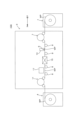
- FIG. 1 is a front view schematically showing a printing system equipped with an example of a printing apparatus according to the present invention
- FIG. FIG. 2 is a partial cross-sectional view schematically showing the configuration of an ejection head
- FIG. 2 is a block diagram showing an electrical configuration included in the printing apparatus of FIG. 1
- 4A and 4B are diagrams schematically showing waveforms of ejection signals output to piezoelectric elements of the ejection head
- FIG. FIG. 4 is a diagram schematically showing details of an ejection signal
- FIG. 4 is a diagram schematically showing residual vibration that occurs as ink is ejected in response to an ejection signal
- FIG. 10 is a table showing the relationship between the size of two ink droplets ejected in succession and the influence of residual vibration;
- FIG. 6 is a diagram schematically showing the relationship between ejection signals when the size of the preceding ink droplet of two ink droplets ejected in succession is L size.
- 4 is a flowchart showing an example of image printing executed by a printing device;
- FIG. 10 is a diagram schematically showing an example of image processing executed according to the flowchart of FIG. 9;
- FIG. 10 is a diagram schematically showing an example of image processing executed according to the flowchart of FIG. 9;
- FIG. FIG. 10 is a diagram schematically showing an example of image processing executed according to the flowchart of FIG. 9;
- FIG. FIG. 10 is a diagram schematically showing an example of image processing executed according to the flowchart of FIG. 9;
- FIG. 10 is a table showing the relationship between the size of two ink droplets ejected in succession and the influence of residual vibration;
- FIG. 10 is a table showing the relationship between the size of two ink droplets ejected in succession and the influence of residual vibration;
- FIG. 10 is a table showing the relationship between the size of two ink droplets ejected in succession and the influence of residual vibration;
- FIG. 10 is a table showing the relationship between the size of two ink droplets ejected in succession and the influence of residual vibration;
- 4 is a block diagram showing an electrical configuration for executing image printing;
- FIG. 10 is a diagram showing image processing executed in a first modified example of interpolation processing;
- FIG. 1 is a front view schematically showing a printing system 100 equipped with an example of the printing apparatus according to the invention.
- the X direction which is the horizontal direction in which the paper feeding unit 1, the printing device 3, and the paper discharging unit 4 constituting the printing system 100 are arranged
- the Y direction which is a horizontal direction perpendicular to the X direction, is shown as appropriate.
- the printing system 100 includes a paper feeding section 1, a printing device 3, and a paper discharging section 4.
- the paper feeding unit 1 holds a print medium WP, which is a roll of continuous paper, rotatably around a horizontal axis.
- the paper feeding unit 1 unwinds and supplies the printing medium WP to the printing device 3 .
- the printing device 3 performs printing by ejecting ink onto the print medium WP to form an image, and delivers the print medium WP to the paper discharge section 4 .
- the paper discharge unit 4 winds the print medium WP printed by the printing device 3 around the horizontal axis.
- the direction in which the print medium WP is sent out and transported by the paper feeding unit 1 is defined as the transport direction X.
- a horizontal direction orthogonal to the transport direction X is defined as a width direction Y.
- the paper feeding unit 1 described above is arranged on the upstream side of the printing device 3 in the transport direction X.
- the above-described paper discharge section 4 is arranged on the downstream side of the printing device 3 in the transport direction X. As shown in FIG.
- the printing device 3 has a drive roller 7 on the upstream side for taking in the print medium WP from the paper feeding unit 1 .
- the print medium WP fetched from the paper feeding unit 1 by the drive roller 7 is sent in the transport direction X by a plurality of transport rollers 9 and transported toward the paper discharge unit 4 on the downstream side.
- a driving roller 11 is arranged between the most downstream conveying roller 9 and the paper discharge section 4 . The driving roller 11 sends out the print medium WP conveyed on the conveying roller 9 toward the paper discharge section 4 .
- the printing device 3 includes a printing unit 13, a drying unit 15, and a line scanner 17 in that order along the transport direction X from the upstream side between the drive roller 7 and the drive roller 11.
- the printing unit 13 prints on the print medium WP.
- the drying unit 15 dries the print medium WP printed by the printing unit 13 .
- the line scanner 17 inspects whether or not the printed portion of the print medium WP is stained or missing.
- the printing unit 13 includes an ejection head 5 having a plurality of nozzles for ejecting ink onto the print medium WP.
- a plurality of printing units 13 are generally arranged along the transport direction X of the print medium WP. For example, a total of four printing units 13 for black (K), cyan (C), magenta (M), and yellow (Y) are provided. However, in the following description, a configuration in which the printing device 3 includes only one printing unit 13 will be described as an example.
- the printing unit 13 has a length that exceeds the width of the print medium WP in the width direction Y of the print medium WP.
- the printing unit 13 includes an ejection head 5 that can print a print area in the width direction of the print medium WP without moving in the width direction Y. As shown in FIG.
- FIG. 2 is a partial cross-sectional view schematically showing the configuration of the ejection head.
- the printing unit 13 has a plurality of ejection heads 5, and each ejection head 5 ejects ink using an inkjet method.
- the ejection head 5 has a housing 51 and a plurality of nozzles 52 arranged in a predetermined direction at the bottom of the housing 51. Each of the plurality of nozzles 52 opens downward.
- a plurality of cavities 53 communicating with the plurality of nozzles 52 and an ink supply chamber 54 communicating with the plurality of cavities 53 are provided inside the housing 51 .
- an inlet 511 and an outlet 512 communicating with the ink supply chamber 54 are opened in the housing 51, and ink supplied from the inlet 511 to the ink supply chamber 54 by an ink circulation mechanism (not shown) flows.
- the ink is cyclically supplied to the ink supply chamber 54 by being collected from the outlet 512 .
- Ink is supplied to each cavity 53 from the ink supply chamber 54 .
- a piezoelectric element 55 is provided for each of the plurality of cavities 53 .
- the piezoelectric element 55 is, for example, a piezoelectric element, and deforms according to an applied electrical signal.
- the pressure of the ink inside the cavity 53 fluctuates according to the deformation of the piezoelectric element 55 .
- an ejection signal which is an electrical signal, is applied to the piezoelectric element 55 .
- the piezoelectric element 55 gives the ink in the cavity 53 pressure fluctuation (ejection pressure fluctuation) required for ejecting ink from the nozzle 52 .
- FIG. 3 is a block diagram showing the electrical configuration of the printing apparatus of FIG.
- the printing apparatus 3 has a transport motor 341 that drives the driving roller 7 to transport the print medium WP, and the rotational position of the transport motor 341 (in other words, the transport position of the print medium WP). and an encoder 342 for detecting.
- the transport motor 341 is a servomotor that rotates the drive roller 7 .
- the printing device 3 also includes a line scanner 17 (line camera).
- the line scanner 17 is arranged perpendicular to the transport direction X of the print medium WP, and passes through an imaging position between the drying section 15 and the discharge section 4, which is located downstream of the printing section 13, for example. An image printed on the recording surface of the print medium WP is captured.
- the printing device 3 includes a control unit 39 that controls the entire device.
- This control unit 39 includes a calculation unit 391 and a storage unit 392 .
- the calculation unit 391 is configured by, for example, a processor such as a CPU (Central Processing Unit) or FPGA (Field-Programmable Gate Array), and the storage unit 392 is a storage device such as a HDD (Hard Disk Drive) or SSD (Solid State Drive).
- the computing unit 391 controls the conveying motor 341 , the encoder 342 , the line scanner 17 and the piezoelectric elements 55 , and the storage unit 392 stores a print program 393 executed by the computing unit 391 .
- This print program 393 is provided, for example, by a recording medium 399 provided separately from the control unit 39 .
- This recording medium 399 records the print program 393 so that it can be read by the computer (control unit 39).
- a recording medium 399 includes, for example, a USB (Universal Serial Bus) memory, a memory card, or a storage device of an external server computer.
- the print program 393 defines the content of control executed by the control unit 39 .
- FIG. 4 is a diagram schematically showing the waveform of the ejection signal output to the piezoelectric element of the ejection head.
- the horizontal axis represents time
- the vertical axis represents voltage.
- the ejection signal Sd is a voltage signal whose voltage changes with the lapse of time.
- the pressure applied to the ink inside the cavity 53 is varied according to the change in . This pressure fluctuation causes ink to be ejected from the nozzle 52 communicating with the cavity 53 .
- the ejection signal Sd is periodically output according to the transport speed of the print medium WP.
- the computing unit 391 calculates the speed at which the print medium WP is transported based on the transport position of the print medium WP detected by the encoder 342 .
- the calculation unit 391 determines the cycle Cs (that is, the time interval) for outputting the ejection signal Sd to the piezoelectric element 55 based on the transport speed of the printing medium WP thus calculated.
- the cycle Cs that is, the time interval
- the calculation unit 391 shortens the cycle Cs of the ejection signal Sd as the transport speed of the print medium WP increases, and shortens the cycle Cs of the ejection signal Sd as the transport speed of the print medium WP decreases. Lengthen the period Cs. That is, the period Cs is inversely proportional to the transport speed.
- FIG. 5 is a diagram schematically showing the details of the ejection signal.
- the horizontal axis represents time
- the vertical axis represents voltage.
- the calculation unit 391 can apply a plurality of element signals Se(1), Se(2), Se(3) shown in FIG.
- Each of the element signals Se(1), Se(2), and Se(3) is a voltage signal whose voltage changes over time.
- Element signal Se(1) is applied from time Ts1 to time Ts2
- element signal Se(2) is applied from time Ts2 to time Ts3
- element signal Se(3) is applied from time Ts3 to time Ts4.
- the time Ts1 corresponds to the start time of the cycle Cs
- the times Ts1 to Ts4 are set so that the period from the time Ts1 to the time Ts4 is equal to or less than the cycle Cs.
- the calculation unit 391 changes the combination of the element signals Se(1), Se(2), and Se(3) forming the ejection signal Sd, thereby obtaining a plurality of ejection signals Sd(s) and Sd(m). , Sd(l).
- the ejection signal Sd(s) is an ejection signal Sd composed of one kind of element signal Se(3)
- the ejection signal Sd(m) is an ejection signal Sd composed of two consecutive element signals Se(2) and Se(3).
- the ejection signal Sd(l) is an ejection signal Sd composed of three consecutive element signals Se(1), Se(2), and Se(3).
- the piezoelectric element 55 When the ejection signal Sd(s) is applied to the piezoelectric element 55, the piezoelectric element 55 ejects an S-sized ink droplet from the nozzle 52. When the ejection signal Sd(m) is applied to the piezoelectric element 55, the piezoelectric element 55 The element 55 ejects an M-sized ink droplet larger than the S size from the nozzle 52. When the ejection signal Sd(l) is applied to the piezoelectric element 55, the piezoelectric element 55 ejects an L-sized ink droplet larger than the M size. is discharged from the nozzle 52 .
- the calculation unit 391 switches the ejection signal Sd to be supplied to the piezoelectric element 55 among the ejection signals Sd(s), S(m), and S(l), thereby adjusting the size (amount) of the ink droplets ejected from the nozzles 52 . ) can be changed.
- FIG. 6 is a diagram schematically showing residual vibrations that occur as ink is ejected in response to an ejection signal.
- the horizontal axis represents time
- the vertical axis represents the position of the meniscus.
- the effect of residual vibration depends on the size of two ink droplets that are ejected consecutively at a period Cs.
- FIG. 7 is a table showing the relationship between the size of two consecutively ejected ink droplets and the influence of residual vibration.
- the preceding ink droplet is the ink droplet that is ejected first among two ink droplets that are continuously ejected from the same nozzle 52, and the succeeding ink droplet is ejected after the preceding ink droplet.
- the influence of the residual vibration to be noted here means the influence of the residual vibration caused by the discharge of the preceding ink droplet on the discharge of the succeeding ink droplet.
- the cause of the latter tendency is considered as follows. That is, as shown in FIG. 5, the larger the ink droplet size, the earlier the ejection signal Sd is started. Therefore, the ejection signal Sd for ejecting the subsequent ink droplet is applied before the residual vibration caused by the ejection of the preceding ink droplet is sufficiently attenuated, and the influence of the residual vibration increases.
- the influence of the residual vibration is small regardless of whether the size of the succeeding ink droplet is S size, M size, or L size. . If the size of the preceding ink droplet is M size and the size of the succeeding ink droplet is S size, the influence of residual vibration is small. If the size of the preceding ink droplet is M size and the size of the succeeding ink droplet is M size or L size, the effect of residual vibration is moderate. When the size of the preceding ink droplet is L size and the size of the succeeding ink droplet is S size, the effect of residual vibration is moderate. If the size of the preceding ink droplet is L size and the size of the succeeding ink droplet is M size or L size, the influence of residual vibration is large.
- FIG. 8 is a diagram schematically showing the relationship between ejection signals when the size of the preceding ink droplet of two ink droplets that are ejected in succession is L size.
- the horizontal axis represents time, and the vertical axis represents voltage.
- the "LS" column indicates the case where the S size ink droplet is ejected after the L size ink droplet is ejected
- the "LM” column indicates the case where the L size ink droplet is ejected and then the S size ink droplet is ejected.
- the case of ejecting an M-size ink droplet is shown
- the column “LL” shows the case of ejecting an L-size ink droplet and then ejecting an L-size ink droplet.
- the ejection signal Sd is applied at each of the timings T(1) and T(2) that are continuous with the cycle Cs (in other words, the periods T(1) and T(2) having the cycle Cs). .
- the ejection signal Sd(l) is applied at timing T1
- the ejection signal Sd(s) is applied at timing T2 after timing T1.
- the ejection signal Sd(s) rises at time Ts3
- the ejection signal Sd(l) is applied at timing T1, and the ejection signal Sd(m) is applied at timing T2 after timing T1.
- the ejection signal Sd(m) rises at time Ts2
- the ejection signal Sd(l) is applied at the timing T1
- the ejection signal Sd(L) is applied at the timing T2 after the timing T1.
- FIG. 9 is a flowchart showing an example of image printing performed by a printing device
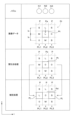
- FIGS. 10A, 10B, and 10C are diagrams schematically showing an example of image processing performed according to the flowchart of FIG.
- the flowchart of FIG. 9 is executed by the calculation unit 391 based on the print program 393 in order to print a good image while suppressing the influence of the residual vibration described above.
- the image data Di is composed of a plurality of pixels P arranged two-dimensionally in the X direction and the Y direction. By ejecting ink droplets from . . . , an image represented by the image data Di is printed on the printing medium WP.
- the pitch Ix at which the pixels P are arranged in the X direction corresponds to the resolution of the image data Di, and corresponds to a value obtained by multiplying the transport speed of the print medium WP by the cycle Cs of the ejection signal Sd.
- a plurality of nozzles N1, N2, N3, . . . face a plurality of pixel columns PL1, PL2, PL3, .
- Each of the pixel columns PL1, PL2, PL3, . . . is composed of a plurality of pixels P arranged in one column in the X direction.
- the nozzles N1, N2, N3, . . . eject ink droplets in synchronization with the transport of the print medium WP in the X direction.
- the nozzles N1, N2, N3, . . . eject ink droplets sequentially from the downstream side in the X direction (conveyance direction) to a plurality of pixels P of the opposing pixel rows PL1, PL2, PL3, .
- the image data Di indicates the size (S, M, L) of ink droplets to be ejected to the pixel P for each pixel P, and the nozzles N1, N2, N3, .
- An ink droplet of the size is ejected onto the pixel P.
- the flowchart of FIG. 9 corrects the image data Di by adjusting the ink droplet size set for each pixel P of the image data Di so that the influence of the residual vibration is suppressed. Specifically, thinning processing is performed to reduce the size of subsequent ink droplets associated with the combination of ink droplets that are greatly affected by the residual vibration shown in FIG. 7 to zero. Note that each of the combinations of ink droplet sizes that are greatly affected by residual vibration is hereinafter appropriately referred to as a “thinning standard”. This thinning reference is stored in the storage unit 392 in advance.
- the computing unit 391 acquires image data Di (step S101).
- the calculation unit 391 may acquire the image data Di by receiving the image data Di generated by an external computer, or generate the image data Di based on the print data received from the external computer.
- the image data Di may be obtained by
- the calculation unit 391 sets the count value Cp of the pixel P (that is, the value for identifying the pixel P) to zero, and increments the count value Cp of the pixel P by "1" in step S103.
- step S104 the calculation unit 391 confirms whether or not there is a preceding pixel P from which ink droplets are ejected prior to the pixel P (target pixel) of the count value Cp. Specifically, the presence of a pixel P (preceding pixel) adjacent to the target pixel P with the count value Cp on the downstream side (arrow side) in the X direction is confirmed. For example, if the target pixel P is located at the edge of the image and the corresponding preceding pixel P does not exist ("NO" in step S104), the process returns to step S103, and the count value Cp of the pixel P is set to 1 only increment.
- the calculation unit 391 determines whether the preceding pixel P and the target pixel P satisfy the thinning criterion. In other words, any of the following two thinning criteria: ⁇ The size of the preceding ink droplet is L size, and the size of the subsequent ink droplet is M size ⁇ The size of the preceding ink droplet is L size, and the size of the succeeding ink droplet is L size. It is determined whether it is satisfied. If none of these thinning criteria are satisfied ("NO" in step S105), the process returns to step S103 without changing the size of the ink droplet to be ejected to the target pixel P.
- step S105 if any of these thinning criteria are satisfied ("YES" in step S105), the process proceeds to step S106.
- thinning criteria are satisfied will be described based on the columns of "image data" in FIGS. 10A to 10C.
- the pixel P adjacent to the target pixel Pt on the downstream side in the X direction is the preceding pixel Pa.
- the size of the ink droplet scheduled to be ejected to the preceding pixel Pa is L size
- the size of the ink droplet scheduled to be ejected to the target pixel Pt is M size, so the thinning criterion is satisfied.
- the pixel P adjacent to the target pixel Pt on the downstream side in the X direction is the preceding pixel Pa.
- the size of the ink droplet scheduled to be ejected to the preceding pixel Pa is L size and the size of the ink droplet scheduled to be ejected to the target pixel Pt is L size, the thinning criterion is satisfied.
- the pixel P adjacent to the target pixel Pt on the downstream side in the X direction is the preceding pixel Pa.
- the size of the ink droplet scheduled to be ejected to the preceding pixel Pa is L size
- the size of the ink droplet scheduled to be ejected to the target pixel Pt is M size, so the thinning criterion is satisfied.
- the ink droplet size of the target pixel Pt is set to zero.
- setting the size of the ink droplet to zero corresponds to not ejecting the ink droplet from the nozzle that was scheduled to eject the ink droplet. 10A to 10C, this thinning process will be specifically described.
- the size of ink droplets scheduled to be ejected onto the target pixel Pt is changed from L size to zero, and in the example of the “thinning processing” of FIG. The size is changed from M size to zero.
- step S107 the calculation unit 391 stores the thinned pixels Pt as thinned pixels Pd in the storage unit 392 for later complement processing. Steps S103 to S107 are repeated until the count value Cp of the pixel P reaches the maximum value Cpx (total number of pixels P forming the image data Di) (until "YES" in step S108).
- the count value Cd for counting the thinned pixels Pd (that is, the value for identifying the thinned pixels Pd) is set to zero (step S109). , the count value Cd of the thinned pixel Pd is incremented by "1" (step S110).
- step S111 complementary processing is executed to compensate for the shortage of the ink amount due to setting the size of the ink droplet for the thinned pixel Pd to zero.
- the size of the ink droplet to be ejected is increased for the adjacent pixel Pj adjacent in the Y direction to the thinned pixel Pd of the count value Cd. For example, if the size of the ink droplet to be ejected to the adjacent pixel Pj is S size, it is increased to M size, and if the size is M size, it is increased to L size. If the size is L size, the size is not increased because there is no larger size.
- This complementary processing will be specifically described using FIGS. 10A to 10C.
- the size of the ink droplet to be ejected to the adjacent pixel Pj adjacent to the thinning pixel Pd on one side (right side) in the Y direction is increased from S size to M size, and On the other side (left side), the size of the ink droplet to be ejected to the adjacent pixel Pj adjacent to the thinned pixel Pd is increased from zero to S size.
- the size of the ink droplet to be ejected to the adjacent pixel Pj adjacent to the thinning pixel Pd on one side (right side) in the Y direction is increased from zero to S size, and
- the size of the ink droplet to be ejected to the adjacent pixel Pj adjacent to the thinned pixel Pd on the side (left side) is increased from M size to L size.
- the size of ink droplets to be ejected to adjacent pixels Pj adjacent to the thinning pixel Pd on one side (right side) in the Y direction is increased from M size to L size. Since the thinned pixel Pd is positioned at the other end in the Y direction, there is no adjacent pixel Pj adjacent to the thinned pixel Pd on the other side (left side) in the Y direction.
- Steps S110 to S111 are repeated until the count value Cd of the thinned pixels Pd reaches the maximum value Cdx (total number of thinned pixels Pd stored in step S107) (until "YES" in step S112). .
- the calculation unit 391 stores the image data Di on which the thinning process and the complementing process are executed as the dot data Dd in the storage unit 392. (Step S113). Then, in step S114, the calculation unit 391 causes the nozzles N1, N2, N3, .
- the size of ink droplets to be ejected to each pixel P defined by the image data Di is corrected. Specifically, the size (first ejection condition) of the ink droplet to be ejected from the nozzle 52 to the preceding pixel Pa at timing T1 (first timing), and the target pixel Pt from the nozzle 52 at timing T2 (second timing) The size (amount) of the ink droplets to be ejected from the nozzles 52 to the target pixel Pt is corrected based on the comparison with the size of the ink droplets scheduled to be ejected (second ejection condition) (steps S105 and S106).
- control unit 39 stores in the storage unit 392 a thinning reference (decrease reference) for reducing the size of the ink droplets ejected from the nozzles 52 to the target pixel Pt at the timing T2 from the size indicated by the image data Di. Then, if the combination of ink droplet sizes for the preceding pixel Pa and the target pixel Pt indicated by the image data Di (in other words, the comparison result) satisfies the thinning standard ("YES" in step S105), the nozzle 52 determines in step S106 that the size of ink droplets to be ejected at timing T2 is reduced (thinning processing).
- a thinning reference decrease reference
- the ink droplets ejected by the nozzles 52 at the timing T2 are determined to be greatly influenced by the residual vibration based on the sizes of the ink droplets on the preceding pixel Pa and the target pixel Pt indicated by the image data Di. can be dealt with by reducing the size of As a result, it is possible to suppress the influence of residual vibration of the ink caused by ejection of ink droplets from the nozzles 52, and to perform good printing.
- the control unit 39 causes the nozzles 52 to perform timing It is determined that the size of ink droplets to be ejected at T2 is zero (thinning processing).
- the ink droplets ejected by the nozzles 52 at the timing T2 are determined to be greatly influenced by the residual vibration based on the sizes of the ink droplets on the preceding pixel Pa and the target pixel Pt indicated by the image data Di. You can fix this by setting the size of . As a result, it is possible to suppress the influence of residual vibration of the ink caused by ejection of ink droplets from the nozzles 52, and to perform good printing.
- a plurality of nozzles N1, N2, N3, . . . are provided, and the plurality of nozzles N1, N2, N3, .
- the control unit 39 determines to reduce the size of the ink droplets ejected by the nozzle N2 at the timing T2 in the thinning process, the control unit 39 controls the nozzle N1, which faces the adjacent pixel Pj adjacent to the target pixel Pt in the Y direction.
- the size of the ink droplet ejected from N3 (adjacent nozzle) to the adjacent pixel Pj is increased from the size indicated by the image data Di (complementary processing).
- the size of the ink droplets ejected by the nozzle N2 at the timing T2 is reduced in order to suppress the influence of the residual vibration.
- the size of the ink droplets ejected from the nozzles N1 and N3 to the adjacent pixel Pj of the target pixel Pt it is possible to make up for the shortage of ink droplets and print a good image. Become.
- FIGS. 11A and 11B are diagrams showing, in table form, the relationship between the size of two ink droplets ejected in succession and the effect of residual vibration. It shows the relationship with the influence of residual vibration. That is, as can be seen from the above description using FIG. 8, the shorter the period Cs of the ejection signal Sd, the shorter the time interval between the ejection signal Sd ejected at timing T1 and the ejection signal Sd ejected at timing T2. and the influence of residual vibration tends to increase.
- step S105 in the flowchart of FIG. 9 it is determined whether or not the period Cs of the ejection signal Sd is less than a threshold period corresponding to a predetermined period. Then, if the period Cs is equal to or greater than the threshold period, the process proceeds to step S108 without executing steps S105 to S107. On the other hand, when the period Cs is less than the threshold period, steps S105 to S107 are executed.
- one threshold cycle is provided for the cycle Cs of the ejection signal Sd.
- a threshold period is set for the boundary where the number of corresponding combinations changes according to the change of the period Cs, and the thinning criterion (that is, residual A combination of ink droplet sizes that increase the influence of vibration) may be changed.
- the control unit 39 controls the combination of the sizes of the ink droplets for the preceding pixel Pa and the target pixel Pt indicated by the image data Di, the cycle Cs of the ejection signal Sd (in other words, the timing T1 and The size of the ink droplet ejected by the nozzle 52 at the timing T2 is determined based on the time interval from the timing T2 (steps S105 to S107). With such a configuration, it is possible to accurately cope with the influence of the residual vibration that varies depending on the period Cs of the ejection signal Sd, and to perform good printing.
- FIGS. 12A and 12B are diagrams showing, in table form, the relationship between the size of two successively ejected ink droplets and the effect of residual vibration. Show relationship. That is, the lower the temperature of the ink in the ejection head 5 is, the higher the viscosity of the ink is, so the influence of residual vibration tends to be smaller.
- the effect of the residual vibration when the ink temperature is equal to or higher than the predetermined temperature (Fig. 12A) is greater than the effect of the residual vibration when the ink temperature is less than the predetermined temperature (Fig. 12B).
- the effect of residual vibration shown in FIG. 12A is the same as that of FIG. 7, whereas in FIG. You don't have the drop size combination you need.
- step S105 in the flowchart of FIG. 9 it is determined whether the ink temperature is equal to or higher than a threshold temperature corresponding to a predetermined temperature.
- the calculation unit 391 can check the temperature of the ink by acquiring the detection value of a thermometer provided in the ink supply chamber 54 of the ejection head 5, for example. Then, if the temperature of the ink is less than the threshold temperature, the process proceeds to step S108 without executing steps S105 to S107. On the other hand, when the ink temperature is equal to or higher than the threshold temperature, steps S105 to S107 are executed.
- one threshold temperature is provided for the ink temperature.
- a threshold temperature is set for the boundary where the number of corresponding combinations changes according to the temperature change of the ink, and the thinning reference (that is, residual A combination of ink droplet sizes that increase the influence of vibration) may be changed.
- the control unit 39 causes the nozzles 52 to eject at the timing T2 based on the combination of the sizes of the ink droplets for the preceding pixel Pa and the target pixel Pt indicated by the image data Di and the temperature of the ink.
- the size of the ink droplet to be printed is determined (steps S105 to S107).
- the printing device 3 corresponds to an example of the "printing device” of the present invention
- the control section 39 corresponds to an example of the "control section” or "computer” of the present invention
- the printing program 393 The recording medium 399 corresponds to an example of the "printing medium” of the present invention
- the ejection head 5 corresponds to an example of the "ejection head” of the present invention
- the pixel P corresponds to an example of the pixel of the present invention
- the target pixel Pt corresponds to an example of the "target pixel” of the present invention
- the adjacent pixel Pj corresponds to an example of the "neighboring pixel" of the present invention.
- Timing T1 corresponds to an example of the "first timing” of the present invention
- timing T2 corresponds to an example of the "second timing” of the present invention
- steps S105 and S106 correspond to an example of the "determining process” of the present invention
- the size (amount) of the ink droplet corresponds to an example of the "ejection condition” of the present invention
- the size of the ink droplet ejected at the timing T1 corresponds to an example of the "first ejection condition" of the present invention.
- the size of the ink droplets ejected at the timing T2 corresponds to an example of the "second ejection condition" of the present invention
- the thinning standard corresponds to an example of the “reduction standard” of the present invention
- the period Cs corresponds to the " This corresponds to an example of "time corresponding to resolution”.
- steps S105 to S107 are executed. Further, even if the temperature of the ink is less than the threshold temperature, if the cycle Cs of the ejection signal Sd is less than the threshold cycle, in FIG. S105 to S107 are executed.
- the ink temperature is equal to or higher than the threshold temperature and the period Cs of the ejection signal Sd is less than the threshold period, the combination of ink droplet sizes that are greatly affected by the residual vibration in FIG. to S107 are executed. Conversely, if the temperature of the ink is less than the threshold temperature and the period Cs of the ejection signal Sd is equal to or greater than the threshold period, the process proceeds to step S108 without executing steps S105 to S107.
- the method of combining the first and second modified examples of image printing is not limited to this example, and can be combined as in the following fourth modified example.
- a table is prepared as a thinning reference in which the degree of influence (small, medium, large) of residual vibration shown in FIGS. 11A, 11B, 12A, and 12B is digitized. This table is prepared for each of FIGS. 11A, 11B, 12A and 12B. Then, a numerical value (periodic reference numerical value) corresponding to the combination of ink droplet sizes and the period Cs of the ejection signal Sd is obtained based on the table (table corresponding to FIG. 11A or 11B).
- step S108 If the product (or sum) of the period reference value and the temperature reference value is less than the predetermined threshold value, the process proceeds to step S108 without executing steps S105 to S107. If the product (or sum) is equal to or greater than the predetermined threshold, steps S105-S107 are executed.
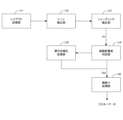
- FIG. 13 is a block diagram showing an electrical configuration for executing image printing.
- Each functional unit U1 to U6 in FIG. 13 is constructed in the arithmetic unit 391 as the print program 393 is executed.
- the layout processing unit U1 arranges the image indicated by the print data received from an external computer, for example, on the print medium WP.
- the print data is data indicating the gradation value of each pixel forming an image, for example, in 256 steps.
- the layout processing unit U1 determines the range in which the image is printed on the print medium WP, and also determines the correspondence between the pixels forming the image and the nozzles 52 .
- the tone correction unit U2 adjusts the color tone of the image data Di by, for example, gamma correction for the print data output from the layout processing unit U1. Perform shading correction on the data.
- the image data Di described above is generated.
- the vibration influence degree determination unit U4 determines whether or not the thinning criteria are satisfied by executing step S105 in FIG.
- the image data Di is data indicating the gradation value of each pixel P forming the image, and is not data directly indicating the size of the ink droplet to be ejected to each pixel P.
- the vibration influence degree determination unit U4 has a table showing the correspondence relationship between the gradation value and the size of the ink droplet, and confirms the size of the ink droplet for each pixel P based on this table. do.
- the thinning complement processing unit U5 executes steps S106, S107, and S109 to S112 for the ink droplet size of the pixel P determined by the vibration influence degree determination unit U4 to satisfy the thinning standard. Then, the sizes of the ink droplets that have undergone each process by the thinning complement processing unit U5 are output to the hatching processing unit U6. On the other hand, the ink droplet size of the pixel P determined by the vibration influence degree determination unit U4 not satisfying the thinning standard is output from the vibration influence degree determination unit U4 to the hatching processing unit U6 without going through the thinning complement processing unit U5. .
- the dot data Dd is input to the halftone dot processing unit U6.
- the halftone dot processing unit U6 executes halftone dot dot processing on the dot data Dd to generate raster data.
- the calculation unit 391 prints an image on the print medium WP by controlling ejection of ink droplets from the nozzles 52 based on the raster data.
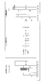
- FIG. 14A is a diagram showing masks used in the first modified example of interpolation processing
- FIG. 14B is a diagram showing image processing performed in the first modified example of interpolation processing.
- the mask in FIG. 14A distributes the gradation value of the thinned pixel Pd to pixels Pj1, Pj2, and Pj3 adjacent to the thinned pixel Pd in the Y direction.
- the adjacent pixels Pj1 (primary adjacent pixels) and the thinned pixels Pd are arranged at a pitch Iy that is one times the pitch Iy, and the adjacent pixels Pj2 (secondary adjacent pixels ) and the thinned pixel Pd are arranged at twice the pitch Iy, and the adjacent pixel Pj3 (tertiary adjacent pixel) and the thinned pixel Pd are arranged at three times the pitch Iy.
- the numerical values of the bar graphs corresponding to the adjacent pixels Pj1, Pj2, and Pj3 represent the gradation value Vd of the thinned-out pixel Pd (that is, the gradation value set to the thinned-out pixel Pd before thinning-out processing) to the adjacent pixels Pj1 and Pj2. , Pj3.
- the result of determining the gradation values to be distributed based on the mask of FIG. 14A for the image data Di whose gradation value Vd is 48 is It is shown in the column "Distribution Value Determination”. As shown in this column, 14, 7, and 3 are distributed as added values to adjacent pixels Pj1, Pj2, and Pj3, respectively.
- the "distribution result” column in FIG. 14B shows the result of adding the addition value to each gradation value for the adjacent pixels Pj1, Pj2, and Pj3.
- the numerical values indicated by the white bar graphs are the gradation values of the adjacent pixels Pj1, Pj2, and Pj3, and the numerical values indicated by the hatched bar graphs are the distributed and added values. Note that the gradation value of the thinned-out pixel Pd is set to zero, as in the above-described embodiment.
- steps S102 to S112 thinning processing/complementing processing
- steps S102 to S112 thinning processing/complementing processing
- the distribution of dots (ink droplets) in the image data Di may be checked, and steps S102 to S112 may be executed by limiting the range where dots are concentrated.
- the above complementing process is not essential, and if the shortage of ink due to the thinning process is not conspicuous, the complementing process may not be executed.
- a combination of ink droplet sizes that increase the influence of residual vibration is adopted as a thinning reference.
- the specific example of the thinning standard is not limited to this.
- a combination of ink droplet sizes with medium or large influence of residual vibration may be adopted as a thinning criterion.
- step S106 it is not necessary to set the ink size of the thinned pixels Pd to zero, and the ink size may be decreased. Decreasing the ink size can be performed, for example, by reducing the ink size by one step.
- the specific example of the "ejection condition" of the present invention is not limited to the size (amount) of the ink droplets described above.
- the effect of residual vibration becomes significant due to a combination of another condition for ejecting ink at timing T1 and another condition for ejecting ink at timing T2, instead of the ink droplet size, The other conditions may be adopted.
- the specific waveforms of the ejection signals Sd(s), Sd(m), and Sd(s) are not limited to the example in FIG.
- the types of the ejection signals Sd are not limited to three types. For example, when changing the size of the ink in four or more stages, the appropriate type of ejection signal Sd may be used.
- the method of ejecting ink is not limited to the method using the piezoelectric element 55 described above.
- the specific mechanism for moving the print medium WP relative to the ejection head 5 is not limited to the above example. That is, instead of transporting the print medium WP by the drive roller 7, the plurality of transport rollers 9, and the drive roller 11, the ejection head 5 may be moved by the carriage.
- the material of the print medium WP described above is continuous paper, it is not limited to this, and may be, for example, sheet paper. Also, the material of the print medium is not necessarily limited to paper, and may be a film such as OPP (oriented polypropylene) or PET (polyethylene terephthalate).
- the present invention is applicable to all inkjet technologies that control the amount of ink droplets ejected from nozzles.
- Printing device 39 Control unit (computer) 393...Printing program 399...Recording medium 5...Ejection head 52...Nozzle N1...Nozzle (adjacent nozzle) N2...Nozzle N3...Nozzle (adjacent nozzle) Di: image data (ejection data) P... pixel Pt... target pixel Pj... adjacent pixel T1... timing (first timing) T2...Timing (second timing) S105-S106... Step (decision process)
Landscapes
- Engineering & Computer Science (AREA)
- Quality & Reliability (AREA)
- Ink Jet (AREA)
- Particle Formation And Scattering Control In Inkjet Printers (AREA)
Abstract
画像データDi(吐出データ)によって規定される各画素Pに吐出予定のインク滴のサイズが補正される。具体的には、タイミングT1(第1タイミング)でノズル52から先行画素Paへ吐出予定のインク滴のサイズ(第1吐出条件)と、タイミングT2(第2タイミング)で当該ノズル52から対象画素Ptへ吐出予定のインク滴のサイズ(第2吐出条件)との比較に基づき、ノズル52が対象画素Ptに吐出するインク滴のサイズ(量)が補正される(ステップS105、S106)。こうして、画像データDiが示す先行画素Paおよび対象画素Ptへのインク滴のサイズに基づき、残留振動の影響が大きくなると判断される状況に対応することができる。
Description
この発明は、ノズルから吐出するインク滴の量を制御するインクジェット技術に関する。
インクジェットヘッドのノズルから吐出したインク滴を印刷媒体に着弾させることで、印刷媒体に画像を印刷する印刷装置が知られている。このような印刷装置では、特許文献1、2に示されるように、ノズルから吐出するインク滴の量を例えばゼロ、スモール(S)、ミドル(M)およびラージ(L)の4段階で調整することで画像の階調を表現することができる。
ところで、インクジェット方式によりインクを吐出したノズルでは、特許文献3に示されるように、ノズルに形成されるインクのメニスカスがインクの吐出に伴って振動する。つまり、インクの吐出から所定の減衰時間が経過するまでは、インクのメニスカスに残留振動が存在する。したがって、先のインク滴の吐出による残留振動が後のインク滴の吐出に影響すると、後のインク滴の吐出を良好に行えない。特に、後述するように、先のインク滴を吐出する際の吐出条件(例えば、インク滴の量)と後のインク滴を吐出する際の吐出条件との関係によっては、残留振動が後のインク滴の吐出に与える影響が顕著となる場合があった。
この発明は上記課題に鑑みなされたものであり、ノズルからのインク滴の吐出に伴うインクの残留振動による影響を抑制して、良好な印刷を行うことを可能とすることを目的とする。
本発明に係る印刷装置は、ノズルからインク滴を吐出する吐出ヘッドと、解像度に応じたピッチで配列される画素のうちノズルが対向する対象画素へノズルからインク滴を吐出する際の吐出条件を示す吐出データに基づき、ノズルからのインク滴の吐出を制御する制御部とを備え、制御部は、第1タイミングでノズルが液滴を吐出する際の吐出条件である第1吐出条件と、第1タイミングから解像度に応じた時間が経過した第2タイミングでノズルが液滴を吐出する際の吐出条件である第2吐出条件との比較に基づき、ノズルが第2タイミングで吐出するインク滴の量を決定する決定処理を実行する。
本発明に係る印刷方法は、解像度に応じたピッチで配列される画素のうちノズルが対向する対象画素へノズルからインク滴を吐出する際の吐出条件を示す吐出データを取得する工程と、第1タイミングでノズルが液滴を吐出する際の吐出条件である第1吐出条件と、第1タイミングから解像度に応じた時間が経過した第2タイミングでノズルが液滴を吐出する際の吐出条件である第2吐出条件との比較に基づき、ノズルが第2タイミングで吐出するインク滴の量を決定する決定処理を実行する工程とを備える。
本発明に係る印刷プログラムは、解像度に応じたピッチで配列される画素のうちノズルが対向する対象画素へノズルからインク滴を吐出する際の吐出条件を示す吐出データを取得する工程と、第1タイミングでノズルが液滴を吐出する際の吐出条件である第1吐出条件と、第1タイミングから解像度に応じた時間が経過した第2タイミングでノズルが液滴を吐出する際の吐出条件である第2吐出条件との比較に基づき、ノズルが第2タイミングで吐出するインク滴の量を決定する決定処理を実行する工程とをコンピュータに実行させる。
本発明に係る記録媒体は、上記の印刷プログラムを、コンピュータにより読み出し可能に記録する。
つまり、第1および第2タイミングで連続してインク液を吐出すると、第1タイミングでのインク滴の吐出に伴うインクの残留振動が第2タイミングでのインク滴の吐出に影響を与えうる。特に、後述するように、第1および第2タイミングそれぞれでのインク液の吐出条件(第1および第2吐出条件)の関係によっては、このような残留振動の影響が顕著になる場合があった。
これに対して、本発明(印刷装置、印刷方法、印刷プログラムおよび記録媒体)では、吐出データが示す第1吐出条件と第2吐出条件との比較(換言すれば、組み合わせ)に基づき、ノズルが第2タイミングで吐出するインク滴の量を決定する(決定処理)。こうして、吐出データが示す第1および第2吐出条件に基づき、残留振動の影響が大きくなると判断される状況に対応することができる。その結果、ノズルからのインク滴の吐出に伴うインクの残留振動による影響を抑制して、良好な印刷を行うことが可能となっている。
また、制御部は、第2タイミングでノズルから対象画素へ吐出するインク滴の量を吐出データが示す量より減少させるための減少基準を記憶し、第1吐出条件と第2吐出条件との比較結果が減少基準を満たす場合には、ノズルが第2タイミングで吐出するインク滴の量を減少させると決定処理で決定するように、印刷装置を構成してもよい。かかる構成では、吐出データが示す第1および第2吐出条件に基づき、残留振動の影響が大きくなると判断される状況に対して、ノズルが第2タイミングで吐出するインク滴の量を減少させることで対応できる。その結果、ノズルからのインク滴の吐出に伴うインクの残留振動による影響を抑制して、良好な印刷を行うことが可能となっている。
また、制御部は、第1吐出条件と第2吐出条件との比較結果が減少基準を満たす場合には、ノズルが第2タイミングで吐出するインク滴の量をゼロにすると決定処理で決定するように、印刷装置を構成してもよい。かかる構成では、吐出データが示す第1および第2吐出条件に基づき、残留振動の影響が大きくなると判断される状況に対して、ノズルが第2タイミングで吐出するインク滴の量をゼロにすることで対応できる。その結果、ノズルからのインク滴の吐出に伴うインクの残留振動による影響を抑制して、良好な印刷を行うことが可能となっている。ここで、ノズルが吐出するインク滴の量をゼロにするとは、ノズルからインク滴を吐出させないことを意味する。
また、吐出ヘッドでは、ノズルを含む複数のノズルが設けられ、複数のノズルは互いに異なる位置にインク滴を吐出し、制御部は、決定処理においてノズルが第2タイミングで吐出するインク滴の量を減少させると決定した場合には、複数のノズルのうち、対象画素に隣接する画素である隣接画素に対向する隣接ノズルから隣接画素に吐出するインク滴の量を吐出データが示す量より増加させるように、印刷装置を構成してもよい。つまり、残留振動の影響を抑制するために、ノズルが第2タイミングで吐出するインク滴の量を減少させたことで、対象画素を含む領域に付着するインク滴の量が不足する場合がある。これに対して、対象画素の隣接画素に隣接ノズルから吐出するインク滴の量を増加させることで、インク滴の量の不足を補って、良好な画像を印刷することが可能となる。
なお、残留振動の影響を顕著にする吐出条件の具体例としては種々想定される。そこで、吐出条件は、ノズルから対象画素へ吐出するインク滴の量を示すように、印刷装置を構成してもよい。
また、制御部は、決定処理において、第1吐出条件と第2吐出条件との比較と、第1タイミングと第2タイミングとの時間間隔とに基づき、ノズルが第2タイミングで吐出するインク滴の量を決定するように、印刷装置を構成してもよい。かかる構成では、第1タイミングと第2タイミングとの時間間隔によって変化する残留振動の影響に的確に対応して、良好な印刷を行うことが可能となる。
また、制御部は、決定処理において、第1吐出条件と第2吐出条件との比較と、インクの温度とに基づき、ノズルが第2タイミングで吐出するインク滴の量を決定するように、印刷装置を構成してもよい。かかる構成では、インクの温度によって変化する残留振動の影響に的確に対応して、良好な印刷を行うことが可能となる。
以上のように、本発明によれば、ノズルからのインク滴の吐出に伴うインクの残留振動による影響を抑制して、良好な印刷を行うことが可能となる。
図1は本発明に係る印刷装置の一例を装備する印刷システム100を模式的に示す正面図である。図1および以下に示す図では、装置各部の配置関係を明確にするために、印刷システム100を構成する給紙部1、印刷装置3および排紙部4を配列する水平方向であるX方向、X方向と直交する水平方向であるY方向を適宜示す。
図1に示すように、印刷システム100は、給紙部1と、印刷装置3と、排紙部4とを備えている。給紙部1は、ロール状の連続紙である印刷媒体WPを水平軸周りに回転可能に保持している。給紙部1は、印刷装置3に対して印刷媒体WPを巻き出して供給する。印刷装置3は、印刷媒体WPに対してインクを吐出して画像を形成することによって印刷を行い、印刷媒体WPを排紙部4に対して送り出す。排紙部4は、印刷装置3で印刷された印刷媒体WPを水平軸周りに巻き取る。
ここでは、給紙部1によって印刷媒体WPが送り出されて搬送される方向を搬送方向Xとする。また、搬送方向Xに直交する水平方向を幅方向Yとする。上述した給紙部1は、搬送方向Xにおける印刷装置3の上流側に配置されている。上述した排紙部4は、搬送方向Xにおける印刷装置3の下流側に配置されている。
印刷装置3は、給紙部1からの印刷媒体WPを取り込むための駆動ローラ7を上流側に備えている。駆動ローラ7によって給紙部1から取り込まれた印刷媒体WPは、複数の搬送ローラ9によって搬送方向Xに送られ、下流側の排紙部4に向かって搬送される。最下流の搬送ローラ9と排紙部4との間には、駆動ローラ11が配置されている。この駆動ローラ11は、搬送ローラ9上を搬送されている印刷媒体WPを排紙部4に向かって送り出す。
印刷装置3は、駆動ローラ7と駆動ローラ11との間に、印刷部13と、乾燥部15と、ラインスキャナ17とを上流側から搬送方向Xに沿ってその順に備えている。印刷部13は、印刷媒体WPに印刷を行う。乾燥部15は、印刷部13によって印刷された印刷媒体WPの乾燥を行う。ラインスキャナ17は、印刷媒体WPに印刷された部分に汚れや抜け等がないかを検査する。
印刷部13は、インクを印刷媒体WPに対して吐出する複数のノズルを有する吐出ヘッド5を備えている。印刷部13は、一般的に、印刷媒体WPの搬送方向Xに沿って複数配置されている。例えば、ブラック(K)、シアン(C)、マゼンタ(M)、イエロー(Y)の合計4個の印刷部13を備えている。但し、以下の説明においては印刷装置3が、1個の印刷部13だけを備えている構成を例にとって説明する。また、印刷部13は、印刷媒体WPの幅方向Yに、印刷媒体WPの幅を超える長さを有する。印刷部13は、幅方向Yに移動することなく印刷媒体WPの幅方向における印刷領域を印刷できるだけの吐出ヘッド5を備えている。
図2は吐出ヘッドの構成を模式的に示す部分断面図である。上述のように、印刷部13は複数の吐出ヘッド5を有し、各吐出ヘッド5はインクジェット方式でインクを吐出する。図2に示すように、吐出ヘッド5は、ハウジング51と、ハウジング51の底部で所定方向に配列された複数のノズル52とを有し、複数のノズル52のそれぞれは下方へ開口する。ハウジング51の内部には、複数のノズル52にそれぞれ連通する複数のキャビティ53と、複数のキャビティ53に連通するインク供給室54とが設けられている。さらに、ハウジング51には、インク供給室54に連通する流入口511および流出口512が開口しており、図示を省略するインク循環機構によって流入口511からインク供給室54に供給されたインクが流出口512から回収されることで、インク供給室54に対してインクが循環的に供給される。かかるインク供給室54から各キャビティ53にインクが供給される。
複数のキャビティ53のそれぞれに対しては、圧電素子55が設けられている。圧電素子55は、例えばピエゾ素子であり、印加された電気信号に応じて変形する。そして、圧電素子55の変形に応じて、キャビティ53内のインクの圧力が変動する。後述するように、この圧電素子55には、電気信号である吐出信号が印加される。吐出信号が圧電素子55に印加されると、圧電素子55は、ノズル52からインクの吐出に要する圧力変動(吐出圧力変動)をキャビティ53内のインクに与える。
図3は図1の印刷装置が備える電気的構成を示すブロック図である。図3に示すように、印刷装置3は、印刷媒体WPを搬送するために駆動ローラ7を駆動する搬送モータ341と、搬送モータ341の回転位置(換言すれば、印刷媒体WPの搬送位置)を検出するエンコーダ342とを備える。搬送モータ341は、駆動ローラ7を回転させるサーボモータである。また、印刷装置3は、ラインスキャナ17(ラインカメラ)を備える。このラインスキャナ17は、印刷媒体WPの搬送方向Xに対して垂直に配置され、例えば、印刷部13より下流側の位置であって、乾燥部15と排出部4との間の撮像位置を通過する印刷媒体WPの記録面に印刷された画像を撮像する。
さらに、印刷装置3は、装置全体を統括的に制御する制御部39を備える。この制御部39は、演算部391と記憶部392とを備える。演算部391は、例えばCPU(Central Processing Unit)などのプロセッサあるいはFPGA(Field-Programmable Gate Array)で構成され、記憶部392は、HDD(Hard Disk Drive)あるいはSSD(Solid State Drive)などの記憶装置で構成される。演算部391は、搬送モータ341、エンコーダ342、ラインスキャナ17および圧電素子55を制御し、記憶部392は、演算部391によって実行される印刷プログラム393を記憶する。この印刷プログラム393は、制御部39とは別に設けられた記録媒体399によって例えば提供される。この記録媒体399は、印刷プログラム393をコンピュータ(制御部39)によって読み出し可能に記録する。かかる記録媒体399としては、例えばUSB(Universal Serial Bus)メモリ、メモリカードあるいは外部のサーバコンピュータの記憶装置などが挙げられる。そして、印刷プログラム393は、制御部39によって実行される制御の内容を規定する。
図4は吐出ヘッドの圧電素子に出力される吐出信号の波形を模式的に示す図である。図4において横軸は時間を表し、縦軸は電圧を表す。図4に示すように、吐出信号Sdは、時間経過とともに電圧が変化する電圧信号であり、演算部391が圧電素子55に吐出信号Sdを出力すると、圧電素子55は、吐出信号Sdが示す電圧の変化に応じて、キャビティ53内のインクに与える圧力を変動させる。この圧力変動によって、キャビティ53に連通するノズル52からインクが吐出される。かかる吐出信号Sdは、印刷媒体WPの搬送速度に応じて周期的に出力される。
詳述すると、演算部391は、エンコーダ342が検出した印刷媒体WPの搬送位置に基づき、印刷媒体WPが搬送される速度を算出する。演算部391は、こうして算出された印刷媒体WPの搬送速度に基づき、吐出信号Sdを圧電素子55に出力する周期Cs(すなわち、時間間隔)を決定する。つまり、印刷媒体WPの搬送速度によらず、印刷媒体WPに一定の解像度でインクを着弾させるには、印刷媒体WPの搬送速度に応じて吐出信号Sdを出力する周期Csを調整する必要がある。具体的には、演算部391は、印刷媒体WPの搬送速度が高くなるのに応じて吐出信号Sdの周期Csを短くし、印刷媒体WPの搬送速度が低くなるのに応じて吐出信号Sdの周期Csを長くする。つまり、周期Csは搬送速度に反比例する。
図5は吐出信号の詳細を模式的に示す図である。図5において横軸は時間を表し、縦軸は電圧を表す。演算部391は、図5に示す複数の要素信号Se(1)、Se(2)、Se(3)を圧電素子55に印加することができる。要素信号Se(1)、Se(2)、Se(3)のそれぞれは、時間経過とともに電圧が変化する電圧信号である。要素信号Se(1)は時刻Ts1から時刻Ts2の間で印加され、要素信号Se(2)は時刻Ts2から時刻Ts3の間で印加され、要素信号Se(3)は時刻Ts3から時刻Ts4の間で印加される。ここで、時刻Ts1は、周期Csの開始時刻に相当し、時刻Ts1から時刻Ts4までの期間が周期Cs以下となるように、時刻Ts1~Ts4は設定されている。
そして、演算部391は、吐出信号Sdを構成する要素信号Se(1)、Se(2)、Se(3)の組み合わせを変更することで、複数の吐出信号Sd(s)、Sd(m)、Sd(l)を生成する。吐出信号Sd(s)は、1種類の要素信号Se(3)によって構成される吐出信号Sdであり、吐出信号Sd(m)は、連続する2種類の要素信号Se(2)、Se(3)によって構成される吐出信号Sdであり、吐出信号Sd(l)は、連続する3種類の要素信号Se(1)、Se(2)、Se(3)によって構成される吐出信号Sdである。吐出信号Sd(s)が圧電素子55に印加されると、圧電素子55は、Sサイズのインク滴をノズル52から吐出させ、吐出信号Sd(m)が圧電素子55に印加されると、圧電素子55は、Sサイズより大きいMサイズのインク滴をノズル52から吐出させ、吐出信号Sd(l)が圧電素子55に印加されると、圧電素子55は、Mサイズより大きいLサイズのインク滴をノズル52から吐出させる。つまり、演算部391は、圧電素子55に与える吐出信号Sdを吐出信号Sd(s)、S(m)、S(l)の間で切り換えることで、ノズル52から吐出するインク滴のサイズ(量)を変更することができる。
ところで、上記のような吐出ヘッド5では、ノズル52からのインクの吐出に伴って残留振動が発生する。この点について、図6を用いて説明する。図6は吐出信号に応じてインクが吐出されるのに伴って生じる残留振動を模式的に示す図である。図6において横軸は時間を表し、縦軸はメニスカスの位置を表す。ノズル52からインクが吐出されると、ノズル52に形成されるインクのメニスカスに振動が生じる。インクの吐出に伴って発生したメニスカスの残留振動は時間経過とともに減衰する。そのため、吐出信号Sdの周期Csが残留振動の減衰時間より長ければ、吐出信号Sdに応じたインクの吐出に対するメニスカスの残留振動の影響はない。一方、吐出信号Sdの周期Csがメニスカスの残留振動の減衰時間より短いと、メニスカスが振動している状態で吐出信号Sdに応じたインクの吐出が行われることとなる。その際、残留振動が吐出信号Sdの逆位相になると吐出信号Sdの信号が減衰し、インクの吐出速度が著しく低下して、印刷媒体WPへのインクの着弾位置が大きくずれる場合があった。特に、残留振動の影響は、周期Csで連続して吐出される2個のインク滴のサイズに依存する。
図7は連続して吐出される2個のインク滴のサイズと残留振動の影響との関係をテーブル形式で示す図である。同図において、先行インク滴は、同一のノズル52から連続して吐出される2個のインク滴のうち先に吐出されるインク滴であり、後続インク滴は、先行インク滴の後に吐出されるインク滴である。また、ここで注目する残留振動の影響とは、先行インク滴の吐出に伴う残留振動が後続インク滴の吐出に与える影響を意味する。
全体的な傾向としては、先行インク滴のサイズが大きいほど、残留振動が後続インク滴の吐出に与える影響は大きく、後続インク滴のサイズが大きいほど、残留振動が後続インク滴の吐出に与える影響は大きい。後者の傾向が生じる要因は次の様に考えられる。つまり、図5に示したように、インク滴のサイズが大きいほど、吐出信号Sdの開始が早くなる。そのため、先行インク滴の吐出に伴う残留振動が十分に減衰しないうちに、後続インク滴の吐出のための吐出信号Sdが印加されてしまい、残留振動の影響が大きくなる。
そのため、図7に示されるように、先行インク滴のサイズがSサイズの場合には、後続インク滴のサイズがSサイズ、MサイズおよびLサイズのいずれであっても、残留振動の影響は小さい。先行インク滴のサイズがMサイズであって、後続インク滴のサイズがSサイズの場合は、残留振動の影響は小さい。先行インク滴のサイズがMサイズであって、後続インク滴のサイズがMサイズあるいはLサイズの場合は、残留振動の影響は中程度である。先行インク滴のサイズがLサイズであって、後続インク滴のサイズがSサイズの場合は、残留振動の影響は中程度である。先行インク滴のサイズがLサイズであって、後続インク滴のサイズがMサイズあるいはLサイズの場合は、残留振動の影響は大きい。
図8は連続して吐出される2個のインク滴のうちの先行インク滴のサイズがLサイズの場合の各吐出信号の関係を模式的に示す図である。図8において横軸は時間を表し、縦軸は電圧を表す。同図において、「LS」の欄は、Lサイズのインク滴を吐出してからSサイズのインク滴を吐出した場合を示し、「LM」の欄は、Lサイズのインク滴を吐出してからMサイズのインク滴を吐出した場合を示し、「LL」の欄は、Lサイズのインク滴を吐出してからLサイズのインク滴を吐出した場合を示す。
これらの例では、周期Csで連続するタイミングT(1)、T(2)(換言すれば、周期Csを有する期間T(1)、T(2))のそれぞれで吐出信号Sdが印加される。「LS」の欄に示す例では、吐出信号Sd(l)がタイミングT1で印加され、吐出信号Sd(s)がタイミングT1の後のタイミングT2で印加される。この際、吐出信号Sd(s)は時刻Ts3に立ち上がるため、先行の吐出信号Sd(l)から後続の吐出信号Sd(s)の立ち上がりまでは、時間間隔Δsが空く。「LM」の欄に示す例では、吐出信号Sd(l)がタイミングT1で印加され、吐出信号Sd(m)がタイミングT1の後のタイミングT2で印加される。この際、吐出信号Sd(m)は時刻Ts2に立ち上がるため、先行の吐出信号Sd(l)から後続の吐出信号Sd(m)の立ち上がりまでは、時間間隔Δmが空く。「LL」の欄に示す例では、吐出信号Sd(l)がタイミングT1で印加され、吐出信号Sd(L)がタイミングT1の後のタイミングT2で印加される。この際、吐出信号Sd(l)は時刻Ts1に立ち上がるため、先行の吐出信号Sd(l)から後続の吐出信号Sd(l)の立ち上がりまでは、時間間隔Δlが空く。
このように、周期Csで2個の吐出信号Sdを印加した場合、後続の吐出信号Sdによって吐出されるインク滴のサイズが大きいほど、2個の吐出信号Sdの間の時間間隔Δs、Δm、Δlが短くなる。その結果、図7を用いて説明した傾向が表れる。
図9は印刷装置により実行される画像印刷の一例を示すフローチャートであり、図10A、図10Bおよび図10Cは図9のフローチャートに従って実行される画像処理の一例を模式的に示す図である。図9のフローチャートは、上述した残留振動の影響を抑制しつつ良好な画像を印刷するために、印刷プログラム393に基づき演算部391により実行される。
図10A~図10Cでは、符号52に変えて符号N1、N2、N3、…をノズル52に対して用いている。これらノズルN1、N2、N3、…はY方向において互いに異なる位置に設けられており、画像データDiに基づきインク滴を吐出する。画像データDiは、X方向およびY方向へ二次元的に配列された複数の画素Pによって構成され、印刷媒体WPに対して仮想的に設定された画素Pに対してノズルN1、N2、N3、…からインク滴を吐出することで、画像データDiが示す画像が印刷媒体WPに印刷される。X方向において画素Pが配列されるピッチIxは画像データDiの解像度に対応しており、印刷媒体WPの搬送速度に吐出信号Sdの周期Csを乗じた値に相当する。
複数のノズルN1、N2、N3、…は、Y方向において隣接する複数の画素列PL1、PL2、PL3、…に対向する。画素列PL1、PL2、PL3、…のそれぞれは、X方向に1列に配列された複数の画素Pで構成される。そして、ノズルN1、N2、N3、…は印刷媒体WPのX方向への搬送に同期してインク滴を吐出する。これによって、ノズルN1、N2、N3、…は、対向する画素列PL1、PL2、PL3、…の複数の画素Pに対して、X方向(搬送方向)の下流側から順にインク滴を吐出する。特に画像データDiは、画素Pに吐出予定のインク滴のサイズ(S、M、L)を各画素Pについて示しており、ノズルN1、N2、N3、…は、画素Pに対して示されたサイズのインク滴を当該画素Pに吐出する。
図9のフローチャートは、上記の残留振動の影響が抑制されるように、画像データDiの各画素Pに対して設定されたインク滴のサイズを調整することで、画像データDiを補正する。具体的には、図7に示した残留振動の影響が大きいインク滴の組み合わせに係る後続のインク滴のサイズをゼロにする間引き処理が実行される。なお、残留振動の影響が大きい上記のインク滴サイズの組み合わせのそれぞれを、以下では「間引き基準」と適宜称する。この間引き基準は記憶部392に予め記憶されている。
図9のフローチャートが開始されると、演算部391は、画像データDiを取得する(ステップS101)。この際、演算部391は、外部のコンピュータで生成された画像データDiを受信することで画像データDiを取得してもよいし、外部のコンピュータから受信した印刷データに基づき画像データDiを生成することで画像データDiを取得してもよい。ステップS102では、演算部391は、画素Pのカウント値Cp(すなわち、画素Pを識別する値)をゼロに設定し、ステップS103では、画素Pのカウント値Cpを「1」だけインクリメントする。
ステップS104では、演算部391は、カウント値Cpの画素P(対象画素)に先行してインク滴が吐出される先行画素Pが存在するか否かを確認する。具体的には、X方向の下流側(矢印側)で、カウント値Cpの対象画素Pに隣接する画素P(先行画素)の存在が確認される。例えば対象画素Pが画像の端に位置しており、該当の先行画素Pが存在しない場合(ステップS104で「NO」の場合)には、ステップS103に戻って、画素Pのカウント値Cpを1だけインクリメントする。
該当の先行画素Pが存在する場合(ステップS104で「YES」の場合)には、演算部391は、先行画素Pと対象画素Pとが、間引き基準を満たすか否かを判断する。つまり、次の2つの間引き基準
・先行インク滴のサイズがLサイズで、後続インク滴のサイズがMサイズ
・先行インク滴のサイズがLサイズで、後続インク滴のサイズがLサイズ
のいずれかが満たされるかが判断される。これら間引き基準のいずれも満たされない場合(ステップS105で「NO」の場合)には、対象画素Pへ吐出予定のインク滴のサイズを変更せずにステップS103に戻る。
・先行インク滴のサイズがLサイズで、後続インク滴のサイズがMサイズ
・先行インク滴のサイズがLサイズで、後続インク滴のサイズがLサイズ
のいずれかが満たされるかが判断される。これら間引き基準のいずれも満たされない場合(ステップS105で「NO」の場合)には、対象画素Pへ吐出予定のインク滴のサイズを変更せずにステップS103に戻る。
一方、これら間引き基準のいずれかが満たされる場合(ステップS105で「YES」の場合)には、ステップS106に進む。ここで、間引き基準が満たされる具体例について、図10A~図10Cそれぞれの「画像データ」の欄に基づき説明する。
図10Aの「画像データ」の欄において実線四角で囲まれた画素Pが対象画素Ptである場合、対象画素Ptに対してX方向の下流側で隣接する画素Pが先行画素Paとなる。この例では、先行画素Paに吐出予定のインク滴のサイズがLサイズであり、対象画素Ptに吐出予定のインク滴のサイズがMサイズであることから、間引き基準が満たされる。
図10Bの「画像データ」の欄において実線四角で囲まれた画素Pが対象画素Ptである場合、対象画素Ptに対してX方向の下流側で隣接する画素Pが先行画素Paとなる。この例では、先行画素Paに吐出予定のインク滴のサイズがLサイズであり、対象画素Ptに吐出予定のインク滴のサイズがLサイズであることから、間引き基準が満たされる。
図10Cの「画像データ」の欄において実線四角で囲まれた画素Pが対象画素Ptである場合、対象画素Ptに対してX方向の下流側で隣接する画素Pが先行画素Paとなる。この例では、先行画素Paに吐出予定のインク滴のサイズがLサイズであり、対象画素Ptに吐出予定のインク滴のサイズがMサイズであることから、間引き基準が満たされる。
ステップS106の間引き処理では、対象画素Ptのインク滴のサイズをゼロにする。ここで、インク滴のサイズをゼロにするとは、当該インク滴を吐出予定であったノズルからインク滴を吐出しないことに相当する。この間引き処理について図10A~図10Cに基づき具体的に説明すると、図10Aの「間引き処理」の例では、対象画素Ptに吐出予定のインク滴のサイズがMサイズからゼロに変更され、図10Bの「間引き処理」の例では、対象画素Ptに吐出予定のインク滴のサイズがLサイズからゼロに変更され、図10Cの「間引き処理」の例では、対象画素Ptに吐出予定のインク滴のサイズがMサイズからゼロに変更される。
ステップS107では、後の補完処理のために、演算部391は、間引き処理を行った画素Ptを間引き画素Pdとして記憶部392に記憶する。そして、画素Pのカウント値Cpが最大値Cpx(画像データDiを構成する画素Pの総数)となるまで(ステップS108で「YES」となるまで)、ステップS103~S107が繰り返し実行される。
画素Pのカウント値Cpが最大値Cpxとなると(ステップS108で「YES」)、間引き画素Pdをカウントするカウント値Cd(すなわち、間引き画素Pdを識別する値)をゼロに設定し(ステップS109)、間引き画素Pdのカウント値Cdを「1」だけインクリメントする(ステップS110)。
ステップS111では、間引き画素Pdに対するインク滴のサイズをゼロにしたことによるインク量の不足を補うための補完処理が実行される。この補完処理では、カウント値Cdの間引き画素Pdに対してY方向において隣接する隣接画素Pjに対して吐出予定のインク滴のサイズを増大させる。例えば、隣接画素Pjに吐出予定のインク滴のサイズがSサイズであればMサイズに増加させ、当該サイズがMサイズであればLサイズに増加させる。なお、当該サイズがLサイズであれば、それより大きいサイズが存在しないため、サイズの増加は行わない。この補完処理について図10A~図10Cを用いて具体的に示す。
図10Aの「補完処理」の例では、Y方向の一方側(右側)で間引き画素Pdに隣接する隣接画素Pjに吐出予定のインク滴のサイズがSサイズからMサイズに増加され、Y方向の他方側(左側)で間引き画素Pdに隣接する隣接画素Pjに吐出予定のインク滴のサイズがゼロからSサイズに増加される。
図10Bの「補完処理」の例では、Y方向の一方側(右側)で間引き画素Pdに隣接する隣接画素Pjに吐出予定のインク滴のサイズがゼロからSサイズに増加され、Y方向の他方側(左側)で間引き画素Pdに隣接する隣接画素Pjに吐出予定のインク滴のサイズがMサイズからLサイズに増加される。
図10Cの「補完処理」の例では、Y方向の一方側(右側)で間引き画素Pdに隣接する隣接画素Pjに吐出予定のインク滴のサイズがMサイズからLサイズに増加される。なお、間引き画素Pdは、Y方向の他方側の端に位置するため、Y方向の他方側(左側)で間引き画素Pdに隣接する隣接画素Pjは存在しない。
そして、間引き画素Pdのカウント値Cdが最大値Cdx(ステップS107で記憶された間引き画素Pdの総数)となるまで(ステップS112で「YES」となるまで)、ステップS110~S111が繰り返し実行される。
間引き画素Pdのカウント値Cdが最大値Cdxとなると(ステップS112で「YES」)、演算部391は、間引き処理および補完処理が実行された画像データDiをドットデータDdとして記憶部392に記憶する(ステップS113)。そして、ステップS114では、演算部391がドットデータDdに示されるサイズのインク滴をノズルN1、N2、N3、…に吐出させることで、画像データDiが示す画像を印刷媒体WPに印刷する。
以上に説明する実施形態では、画像データDi(吐出データ)によって規定される各画素Pに吐出予定のインク滴のサイズが補正される。具体的には、タイミングT1(第1タイミング)でノズル52から先行画素Paへ吐出予定のインク滴のサイズ(第1吐出条件)と、タイミングT2(第2タイミング)で当該ノズル52から対象画素Ptへ吐出予定のインク滴のサイズ(第2吐出条件)との比較に基づき、ノズル52が対象画素Ptに吐出するインク滴のサイズ(量)が補正される(ステップS105、S106)。こうして、画像データDiが示す先行画素Paおよび対象画素Ptへのインク滴のサイズに基づき、残留振動の影響が大きくなると判断される状況に対応することができる。その結果、ノズル52からのインク滴の吐出に伴うインクの残留振動による影響を抑制して、良好な印刷を行うことが可能となっている。
また、制御部39は、タイミングT2でノズル52から対象画素Ptへ吐出するインク滴のサイズを画像データDiが示すサイズより減少させるための間引き基準(減少基準)を記憶部392に記憶する。そして、画像データDiが示す先行画素Paおよび対象画素Ptへのインク滴のサイズの組み合わせ(換言すれば、比較結果)が間引き基準を満たす場合(ステップS105で「YES」の場合)には、ノズル52がタイミングT2で吐出するインク滴のサイズを減少させるとステップS106で決定する(間引き処理)。かかる構成では、画像データDiが示す先行画素Paおよび対象画素Ptへのインク滴のサイズに基づき、残留振動の影響が大きくなると判断される状況に対して、ノズル52がタイミングT2で吐出するインク滴のサイズを減少させることで対応できる。その結果、ノズル52からのインク滴の吐出に伴うインクの残留振動による影響を抑制して、良好な印刷を行うことが可能となっている。
また、制御部39は、画像データDiが示す先行画素Paおよび対象画素Ptへのインク滴のサイズの組み合わせが間引き基準を満たす場合(ステップS105で「YES」の場合)には、ノズル52がタイミングT2で吐出するインク滴のサイズをゼロにすると決定する(間引き処理)。かかる構成では、画像データDiが示す先行画素Paおよび対象画素Ptへのインク滴のサイズに基づき、残留振動の影響が大きくなると判断される状況に対して、ノズル52がタイミングT2で吐出するインク滴のサイズをゼロにすることで対応できる。その結果、ノズル52からのインク滴の吐出に伴うインクの残留振動による影響を抑制して、良好な印刷を行うことが可能となっている。
また、吐出ヘッド5では、複数のノズルN1、N2、N3、…が設けられ、複数のノズルN1、N2、N3、…はY方向において互いに異なる位置にインク滴を吐出する。一方、制御部39は、間引き処理においてノズルN2がタイミングT2で吐出するインク滴のサイズを減少させると決定した場合には、Y方向において対象画素Ptに隣接する隣接画素Pjに対向するノズルN1、N3(隣接ノズル)から隣接画素Pjに吐出するインク滴のサイズを画像データDiが示すサイズより増加させる(補完処理)。つまり、残留振動の影響を抑制するために、ノズルN2がタイミングT2で吐出するインク滴のサイズを減少させたことで、対象画素Ptを含む領域に付着するインク滴の量が不足する場合がある。これに対して、対象画素Ptの隣接画素PjにノズルN1、N3から吐出するインク滴のサイズを増加させることで、インク滴の量の不足を補って、良好な画像を印刷することが可能となる。
続いては、画像印刷の第1変形例について図11Aおよび図11Bを用いて説明する。ここで、図11Aおよび図11Bは連続して吐出される2個のインク滴のサイズと残留振動の影響との関係をテーブル形式で示す図であり、特に吐出信号Sdが出力される周期Csと残留振動の影響との関係を示す。つまり、図8を用いた上記の説明から分かるように、吐出信号Sdの周期Csが短くなるほど、タイミングT1で吐出される吐出信号SdとタイミングT2で吐出される吐出信号Sdとの時間間隔が短くなり、残留振動の影響が大きくなる傾向がある。
したがって、周期Csが所定周期未満の場合における残留振動の影響(図11A)は、周期Csが所定周期以上の場合における残留振動の影響(図11B)よりも大きくなる。その結果、図11Aに示す残留振動の影響は、図7のそれと同じである一方、図11Bでは、残留振動の影響が大きくなるインク滴サイズの組み合わせが存在せず、換言すれば、間引き処理を必要とするインク滴サイズの組み合わせがない。
そこで、画像印刷の第1変形例では、図9のフローチャートのステップS105の前に、吐出信号Sdの周期Csが所定周期に相当する閾周期未満であるか否かを判断する。そして、周期Csが閾周期以上である場合には、ステップS105~S107を実行せずにステップS108に進む。一方、周期Csが閾周期未満である場合には、ステップS105~S107を実行する。
なお、この第1変形例では、吐出信号Sdの周期Csに対して1個の閾周期が設けられる。ただし、周期Csがさらに短い領域では、残留振動の影響が大きくなるインク滴のサイズの組み合わせの個数が増えることも想定される。このような場合には、周期Csの変化に応じて該当の組み合わせの個数が変わる境界に対して閾周期を設定して、周期Csと閾周期との比較に応じて、間引き基準(すなわち、残留振動の影響が大きくなるインク滴のサイズの組み合わせ)を変更してもよい。
このように第1変形例では、制御部39は、画像データDiが示す先行画素Paおよび対象画素Ptへのインク滴のサイズの組み合わせと、吐出信号Sdの周期Cs(換言すれば、タイミングT1とタイミングT2との時間間隔)とに基づき、ノズル52がタイミングT2で吐出するインク滴のサイズを決定する(ステップS105~S107)。かかる構成では、吐出信号Sdの周期Csによって変化する残留振動の影響に的確に対応して、良好な印刷を行うことが可能となる。
次に、画像印刷の第2変形例について図12Aおよび図12Bを用いて説明する。ここで、図12Aおよび図12Bは連続して吐出される2個のインク滴のサイズと残留振動の影響との関係をテーブル形式で示す図であり、特にインクの温度と残留振動の影響との関係を示す。つまり、吐出ヘッド5内のインクの温度が低くなるほど、インクの粘度が高くなるため、残留振動の影響が小さくなる傾向がある。
したがって、インクの温度が所定温度以上の場合における残留振動の影響(図12A)は、インクの温度が所定温度未満の場合における残留振動の影響(図12B)よりも大きくなる。その結果、図12Aに示す残留振動の影響は、図7のそれと同じである一方、図12Bでは、残留振動の影響が大きくなるインク滴サイズの組み合わせが存在せず、換言すれば、間引き処理を必要とするインク滴サイズの組み合わせがない。
そこで、画像印刷の第2変形例では、図9のフローチャートのステップS105の前に、インクの温度が所定温度に相当する閾温度以上であるか否かを判断する。なお、演算部391は、例えば吐出ヘッド5のインク供給室54内に設けられた温度計の検出値を取得することで、インクの温度を確認することができる。そして、インクの温度が閾温度未満である場合には、ステップS105~S107を実行せずにステップS108に進む。一方、インクの温度が閾温度以上である場合には、ステップS105~S107を実行する。
なお、この第2変形例では、インクの温度に対して1個の閾温度が設けられる。ただし、インクの温度がさらに高い領域では、残留振動の影響が大きくなるインク滴のサイズの組み合わせの個数が増えることも想定される。このような場合には、インクの温度変化に応じて該当の組み合わせの個数が変わる境界に対して閾温度を設定して、周期Csと閾温度との比較に応じて、間引き基準(すなわち、残留振動の影響が大きくなるインク滴のサイズの組み合わせ)を変更してもよい。
このように第2変形例では、制御部39は、画像データDiが示す先行画素Paおよび対象画素Ptへのインク滴のサイズの組み合わせと、インクの温度とに基づき、ノズル52がタイミングT2で吐出するインク滴のサイズを決定する(ステップS105~S107)。かかる構成では、インクの温度によって変化する残留振動の影響に的確に対応して、良好な印刷を行うことが可能となる。
以上に説明した実施形態では、印刷装置3が本発明の「印刷装置」の一例に相当し、制御部39が本発明の「制御部」あるいは「コンピュータ」の一例に相当し、印刷プログラム393が本発明の「印刷プログラム」の一例に相当し、記録媒体399が本発明の「記録媒体」の一例に相当し、吐出ヘッド5が本発明の「吐出ヘッド」の一例に相当し、ノズル52、N1、N2、N3、…が本発明の「ノズル」の一例に相当し、ノズルN1、N3が本発明の「隣接ノズル」の一例に相当し、画像データDiが本発明の「吐出データ」の一例に相当し、画素Pが本発明の画素の一例に相当し、対象画素Ptが本発明の「対象画素」の一例に相当し、隣接画素Pjが本発明の「隣接画素」の一例に相当し、タイミングT1が本発明の「第1タイミング」の一例に相当し、タイミングT2が本発明の「第2タイミング」の一例に相当し、ステップS105~S106が本発明の「決定処理」の一例に相当し、インク滴のサイズ(量)が本発明の「吐出条件」の一例に相当し、タイミングT1で吐出されるインク滴のサイズが本発明の「第1吐出条件」の一例に相当し、タイミングT2で吐出されるインク滴のサイズが本発明の「第2吐出条件」の一例に相当し、間引き基準が本発明の「減少基準」の一例に相当し、周期Csが本発明の「解像度に応じた時間」の一例に相当する。
なお、本発明は上記した実施形態に限定されるものではなく、その趣旨を逸脱しない限りにおいて上述したもの以外に種々の変更を行うことが可能である。例えば、画像印刷の第1・第2変形例を組み合わせた第3変形例を実行してもよい。
画像印刷の第3変形例では、吐出信号Sdの周期Csが閾周期以上であっても、インクの温度が閾温度以上である場合には、図7において残留振動の影響が大きいインク滴のサイズの組み合わせを間引き基準としてステップS105~S107を実行する。また、インクの温度が閾温度未満であっても、吐出信号Sdの周期Csが閾周期未満である場合には、図7において残留振動の影響が大きいインク滴のサイズの組み合わせを間引き基準としてステップS105~S107を実行する。さらに、インクの温度が閾温度以上であって、吐出信号Sdの周期Csが閾周期未満である場合には、図7において残留振動の影響が大きいインク滴のサイズの組み合わせを間引き基準としてステップS105~S107を実行する。逆に、インクの温度が閾温度未満であって、吐出信号Sdの周期Csが閾周期以上である場合には、ステップS105~S107を実行せずにステップS108に進む。
また、画像印刷の第1・第2変形例の組み合わせ方は、この例に限られず、次の第4変形例のように組み合わせることもできる。この第4変形例では、図11A、図11B、図12Aおよび図12Bに示した残留振動の影響度(小・中・大)を数値化したテーブルが間引き基準として用意される。このテーブルは、図11A、図11B、図12Aおよび図12Bそれぞれについて用意される。そして、インク滴のサイズの組み合わせと吐出信号Sdの周期Csに対応する数値(周期参照数値)がテーブル(図11Aあるいは図11Bに対応するテーブル)に基づき求められる。同様に、インク滴のサイズの組み合わせとインクの温度に対応する数値(温度参照数値)がテーブル(図12Aあるいは図12Bに対応するテーブル)に基づき求められる。そして、周期参照数値と温度参照数値との積(あるいは和)が所定の閾値未満である場合には、ステップS105~S107を実行せずにステップS108に進み、周期参照数値と温度参照数値との積(あるいは和)が所定の閾値以上である場合には、ステップS105~S107を実行する。
あるいは、図9の画像印刷を実行するために、図13に示す構成を演算部391に構築してもよい。図13は画像印刷を実行する電気的構成を示すブロック図である。図13の各機能部U1~U6は、印刷プログラム393の実行に伴って演算部391に構築される。
レイアウト処理部U1は、例えば外部のコンピュータから受信した印刷データが示す画像を印刷媒体WPに対して配置する。印刷データは、画像を構成する各画素の階調値を例えば256段階で示すデータである。このレイアウト処理部U1によって、印刷媒体WPのうち画像が印刷される範囲が決定されるとともに、画像を構成する画素とノズル52との対応関係が決定される。トーン補正部U2は、レイアウト処理部U1から出力された印刷データに対して、例えばガンマ補正によって画像データDiの色調を調整し、シェーディング補正部U3は、トーン補正部U2によって色調が調整された印刷データに対してシェーディング補正を行う。
こうして、上述の画像データDiが生成される。振動影響度判定部U4は、図9のステップS105を実行することで、間引き基準を満たすか否かを判定する。なお、この例では、画像データDiは、画像を構成する各画素Pの階調値を示すデータであり、各画素Pに吐出予定のインク滴のサイズを直接示すデータではない。これに対して、振動影響度判定部U4は、階調値とインク滴のサイズとの対応関係を示すテーブルを有しており、このテーブルに基づき、各画素Pへのインク滴のサイズを確認する。
そして、振動影響度判定部U4が間引き基準を満たすと判定した画素Pのインク滴サイズに対しては、間引き補完処理部U5が、ステップS106、S107、S109~S112を実行する。そして、間引き補完処理部U5による各処理を受けたインク滴のサイズが網掛け処理部U6に出力される。一方、振動影響度判定部U4が間引き基準を満たさないと判定した画素Pのインク滴サイズは、間引き補完処理部U5を介さずに振動影響度判定部U4から網掛け処理部U6に出力される。
こうして、網掛け処理部U6にはドットデータDdが入力される。この網掛け処理部U6はドットデータDdに対して網掛け処理を実行して、ラスターデータを生成する。そして、演算部391は、ラスターデータに基づきノズル52からのインク滴の吐出を制御することで、印刷媒体WPに画像を印刷する。
さらに、図9のステップS111での補間処理の具体的な態様を次のように変形してもよい。図14Aは補完処理の第1変形例で使用されるマスクを示す図であり、図14Bは補間処理の第1変形例で実行される画像処理を示す図である。図14Aのマスクは、間引き画素Pdの階調値を、Y方向において間引き画素Pdに隣接する画素Pj1、Pj2、Pj3に分配する。ここで、画素PがY方向に配列されるピッチIyに対して、隣接画素Pj1(1次隣接画素)と間引き画素PdとはピッチIyの1倍で配列され、隣接画素Pj2(2次隣接画素)と間引き画素PdとはピッチIyの2倍で配列され、隣接画素Pj3(3次隣接画素)と間引き画素PdとはピッチIyの3倍で配列される。
隣接画素Pj1、Pj2、Pj3に対応する棒グラフの数値は、間引き画素Pdの階調値Vd(すなわち、間引き処理の前に間引き画素Pdに設定されていた階調値)を当該隣接画素Pj1、Pj2、Pj3に分配する比率を示す。隣接画素Pj1、Pj2、Pj3それぞれの数値は、70(=20+20+10+10+5+5)である。したがって、隣接画素Pj1には、階調値Vd×20/70が分配され、隣接画素Pj2には、階調値Vd×10/70が分配され、隣接画素Pj3には、階調値Vd×5/70が分配される。
図14Bの「画像データ」の欄に示されるように、階調値Vdが48の画像データDiに対して、図14Aのマスクに基づき分配される階調値を決定した結果が、図14Bの「分配値決定」の欄に示される。この欄に示されるように、隣接画素Pj1、Pj2、Pj3のそれぞれには、14、7、3が加算値として分配される。図14Bの「分配結果」の欄では、隣接画素Pj1、Pj2、Pj3について、それぞれの階調値に加算値を加えた結果が示される。同欄において、白抜きの棒グラフに示される数値が隣接画素Pj1、Pj2、Pj3の階調値であり、ハッチングが付された棒グラフに示される数値が分配・加算された値である。なお、上述の実施例と同様に、間引き画素Pdの階調値はゼロに設定される。
さらに、上記以外の変形を適宜加えることができる。例えば、図9の画像印刷において、ステップS102~S112(間引き処理・補完処理)を、画像データDiを構成する全ての画素Pを対象に実行する必要はない。例えば、画像データDiにおけるドット(インク滴)の分布を確認して、ドットが集中している範囲に限定してステップS102~S112を実行してもよい。
また、上記の補完処理は必須ではなく、間引き処理によるインク量の不足が顕著でない場合には、補完処理を実行しなくてもよい。
また、上記の実施例では、残留振動の影響が大きくなるインク滴サイズの組み合わせを間引き基準として採用する。しかしながら、間引き基準の具体例はこれに限られない。つまり、残留振動の影響が中あるいは大であるインク滴サイズの組み合わせを間引き基準として採用してもよい。
また、間引き処理(ステップS106)において、間引き画素Pdのインクサイズをゼロにする必要はなく、当該インクサイズを減少させればよい。インクサイズの減少は、例えば、インクサイズを1段階小さくすることで実行することができる。
また、本発明の「吐出条件」の具体例は、上記のインク滴のサイズ(量)に限られない。例えば、タイミングT1でインクを吐出する他の条件と、タイミングT2でインクを吐出する当該他の条件との組み合わせによって残留振動の影響が顕著になるような場合には、インク滴のサイズに代えて当該他の条件を採用すればよい。
また、吐出信号Sd(s)、Sd(m)、Sd(s)の具体的な波形は図5の例に限られない。さらに、吐出信号Sdの種類は3種類に限られず、例えばインクのサイズを4段階以上で変更する場合には、それに応じた種類の吐出信号Sdを用いればよい。
また、インクを吐出する方法は、上記の圧電素子55による方法に限られない。
また、吐出ヘッド5に対して印刷媒体WPを相対的に移動させる具体的機構は上記の例に限られない。つまり、駆動ローラ7、複数の搬送ローラ9および駆動ローラ11により印刷媒体WPを搬送するのに代えて、キャリッジによって吐出ヘッド5を移動させてもよい。
また、上記した印刷媒体WPの素材は、連続紙であったが、それに限られるものではなく、例えば、枚葉の紙であってもよい。また、印刷媒体の素材は、必ずしも紙に限られるものではなく、例えば、OPP(oriented polypropylene)あるいはPET(polyethylene terephthalate)等のフィルムであってもよい。
本発明は、ノズルから吐出するインク滴の量を制御するインクジェット技術の全般に適用可能である。
3…印刷装置
39…制御部(コンピュータ)
393…印刷プログラム
399…記録媒体
5…吐出ヘッド
52…ノズル
N1…ノズル(隣接ノズル)
N2…ノズル
N3…ノズル(隣接ノズル)
Di…画像データ(吐出データ)
P…画素
Pt…対象画素
Pj…隣接画素
T1…タイミング(第1タイミング)
T2…タイミング(第2タイミング)
S105~S106…ステップ(決定処理)
39…制御部(コンピュータ)
393…印刷プログラム
399…記録媒体
5…吐出ヘッド
52…ノズル
N1…ノズル(隣接ノズル)
N2…ノズル
N3…ノズル(隣接ノズル)
Di…画像データ(吐出データ)
P…画素
Pt…対象画素
Pj…隣接画素
T1…タイミング(第1タイミング)
T2…タイミング(第2タイミング)
S105~S106…ステップ(決定処理)
Claims (10)
- ノズルからインク滴を吐出する吐出ヘッドと、
解像度に応じたピッチで配列される画素のうち前記ノズルが対向する対象画素へ前記ノズルからインク滴を吐出する際の吐出条件を示す吐出データに基づき、前記ノズルからのインク滴の吐出を制御する制御部と
を備え、
前記制御部は、第1タイミングで前記ノズルが液滴を吐出する際の前記吐出条件である第1吐出条件と、前記第1タイミングから前記解像度に応じた時間が経過した第2タイミングで前記ノズルが液滴を吐出する際の前記吐出条件である第2吐出条件との比較に基づき、前記ノズルが前記第2タイミングで吐出するインク滴の量を決定する決定処理を実行する印刷装置。 - 前記制御部は、前記第2タイミングで前記ノズルから前記対象画素へ吐出するインク滴の量を前記吐出データが示す量より減少させるための減少基準を記憶し、前記第1吐出条件と前記第2吐出条件との比較結果が前記減少基準を満たす場合には、前記ノズルが前記第2タイミングで吐出するインク滴の量を減少させると前記決定処理で決定する請求項1に記載の印刷装置。
- 前記制御部は、前記第1吐出条件と前記第2吐出条件との比較結果が前記減少基準を満たす場合には、前記ノズルが前記第2タイミングで吐出するインク滴の量をゼロにすると前記決定処理で決定する請求項2に記載の印刷装置。
- 前記吐出ヘッドでは、前記ノズルを含む複数のノズルが設けられ、前記複数のノズルは互いに異なる位置にインク滴を吐出し、
前記制御部は、前記決定処理において前記ノズルが前記第2タイミングで吐出するインク滴の量を減少させると決定した場合には、前記複数のノズルのうち、前記対象画素に隣接する前記画素である隣接画素に対向する隣接ノズルから前記隣接画素に吐出するインク滴の量を前記吐出データが示す量より増加させる請求項2または3に記載の印刷装置。 - 前記吐出条件は、前記ノズルから前記対象画素へ吐出するインク滴の量を示す請求項1ないし4のいずれか一項に記載の印刷装置。
- 前記制御部は、前記決定処理において、前記第1吐出条件と前記第2吐出条件との比較と、前記第1タイミングと前記第2タイミングとの時間間隔とに基づき、前記ノズルが前記第2タイミングで吐出するインク滴の量を決定する請求項1ないし5のいずれか一項に記載の印刷装置。
- 前記制御部は、前記決定処理において、前記第1吐出条件と前記第2吐出条件との比較と、インクの温度とに基づき、前記ノズルが前記第2タイミングで吐出するインク滴の量を決定する請求項1ないし6のいずれか一項に記載の印刷装置。
- 解像度に応じたピッチで配列される画素のうちノズルが対向する対象画素へ前記ノズルからインク滴を吐出する際の吐出条件を示す吐出データを取得する工程と、
第1タイミングで前記ノズルが液滴を吐出する際の前記吐出条件である第1吐出条件と、前記第1タイミングから前記解像度に応じた時間が経過した第2タイミングで前記ノズルが液滴を吐出する際の前記吐出条件である第2吐出条件との比較に基づき、前記ノズルが前記第2タイミングで吐出するインク滴の量を決定する決定処理を実行する工程と
を備える印刷方法。 - 解像度に応じたピッチで配列される画素のうちノズルが対向する対象画素へ前記ノズルからインク滴を吐出する際の吐出条件を示す吐出データを取得する工程と、
第1タイミングで前記ノズルが液滴を吐出する際の前記吐出条件である第1吐出条件と、前記第1タイミングから前記解像度に応じた時間が経過した第2タイミングで前記ノズルが液滴を吐出する際の前記吐出条件である第2吐出条件との比較に基づき、前記ノズルが前記第2タイミングで吐出するインク滴の量を決定する決定処理を実行する工程と
を、コンピュータに実行させる印刷プログラム。 - 請求項9に記載の印刷プログラムを、コンピュータにより読み出し可能に記録する記録媒体。
Priority Applications (1)
| Application Number | Priority Date | Filing Date | Title |
|---|---|---|---|
| US18/575,164 US12311679B2 (en) | 2021-07-30 | 2022-07-19 | Printing apparatus, printing method, printing program and recording medium |
Applications Claiming Priority (2)
| Application Number | Priority Date | Filing Date | Title |
|---|---|---|---|
| JP2021-124972 | 2021-07-30 | ||
| JP2021124972A JP7736477B2 (ja) | 2021-07-30 | 2021-07-30 | 印刷装置、印刷方法、印刷プログラムおよび記録媒体 |
Publications (1)
| Publication Number | Publication Date |
|---|---|
| WO2023008244A1 true WO2023008244A1 (ja) | 2023-02-02 |
Family
ID=85087557
Family Applications (1)
| Application Number | Title | Priority Date | Filing Date |
|---|---|---|---|
| PCT/JP2022/027966 Ceased WO2023008244A1 (ja) | 2021-07-30 | 2022-07-19 | 印刷装置、印刷方法、印刷プログラムおよび記録媒体 |
Country Status (3)
| Country | Link |
|---|---|
| US (1) | US12311679B2 (ja) |
| JP (1) | JP7736477B2 (ja) |
| WO (1) | WO2023008244A1 (ja) |
Citations (3)
| Publication number | Priority date | Publication date | Assignee | Title |
|---|---|---|---|---|
| JP2006205717A (ja) * | 2004-12-27 | 2006-08-10 | Seiko Epson Corp | 印刷装置、印刷プログラム、印刷方法、および画像処理装置、画像処理プログラム、画像処理方法、並びに前記プログラムを記録した記録媒体 |
| JP2014058091A (ja) * | 2012-09-18 | 2014-04-03 | Ricoh Co Ltd | 液滴吐出ヘッド及び画像形成装置 |
| JP2019136927A (ja) * | 2018-02-09 | 2019-08-22 | セイコーエプソン株式会社 | 画像処理装置、画像処理方法および印刷システム |
Family Cites Families (3)
| Publication number | Priority date | Publication date | Assignee | Title |
|---|---|---|---|---|
| JP2001277484A (ja) | 2000-03-31 | 2001-10-09 | Brother Ind Ltd | 画像記録装置 |
| JP2008126453A (ja) | 2006-11-17 | 2008-06-05 | Ricoh Co Ltd | 画像処理方法、プログラム、記憶媒体、画像処理装置、画像形成装置 |
| JP5645550B2 (ja) | 2010-08-27 | 2014-12-24 | 富士フイルム株式会社 | インクジェット記録装置及び方法 |
-
2021
- 2021-07-30 JP JP2021124972A patent/JP7736477B2/ja active Active
-
2022
- 2022-07-19 US US18/575,164 patent/US12311679B2/en active Active
- 2022-07-19 WO PCT/JP2022/027966 patent/WO2023008244A1/ja not_active Ceased
Patent Citations (3)
| Publication number | Priority date | Publication date | Assignee | Title |
|---|---|---|---|---|
| JP2006205717A (ja) * | 2004-12-27 | 2006-08-10 | Seiko Epson Corp | 印刷装置、印刷プログラム、印刷方法、および画像処理装置、画像処理プログラム、画像処理方法、並びに前記プログラムを記録した記録媒体 |
| JP2014058091A (ja) * | 2012-09-18 | 2014-04-03 | Ricoh Co Ltd | 液滴吐出ヘッド及び画像形成装置 |
| JP2019136927A (ja) * | 2018-02-09 | 2019-08-22 | セイコーエプソン株式会社 | 画像処理装置、画像処理方法および印刷システム |
Also Published As
| Publication number | Publication date |
|---|---|
| US12311679B2 (en) | 2025-05-27 |
| JP7736477B2 (ja) | 2025-09-09 |
| JP2023019905A (ja) | 2023-02-09 |
| US20240308234A1 (en) | 2024-09-19 |
Similar Documents
| Publication | Publication Date | Title |
|---|---|---|
| JP4992788B2 (ja) | 補正値算出方法、及び、液体吐出方法 | |
| JP5310754B2 (ja) | 液滴吐出装置およびそのプログラム | |
| JP5911760B2 (ja) | 画像形成装置 | |
| JP6064745B2 (ja) | 液体吐出装置及び液体吐出方法 | |
| US9050840B2 (en) | Printing apparatus and method for correcting printing position shift | |
| JP2009234115A (ja) | 補正値算出方法、及び、液体吐出方法 | |
| JP6042295B2 (ja) | 記録ヘッド及びその製造方法並びに記録装置 | |
| JP6688627B2 (ja) | インクジェット印刷装置 | |
| JP5363262B2 (ja) | 画像記録装置及び画像記録方法 | |
| JP7736477B2 (ja) | 印刷装置、印刷方法、印刷プログラムおよび記録媒体 | |
| JP6643023B2 (ja) | インクジェット記録装置、インクジェット記録方法およびプログラム | |
| JP2017159493A (ja) | インクジェット印刷装置 | |
| JP6036392B2 (ja) | 印刷装置および印刷装置の制御方法 | |
| US10421296B2 (en) | Image forming apparatus, control method thereof, and examination method | |
| JP5698595B2 (ja) | 画像記録装置 | |
| JP2016013645A (ja) | インクジェット印刷装置 | |
| JP2008246859A (ja) | 位置補正システム及び位置補正方法 | |
| WO2022202222A1 (ja) | 印刷装置、印刷方法、印刷プログラムおよび記録媒体 | |
| JP7216203B2 (ja) | インクジェット印刷装置、ダミージェット方法及びプログラム | |
| US20220024221A1 (en) | Method and device for increasing the print quality of an inkjet printing device | |
| JP2009148945A (ja) | 画像記録装置、画像記録装置の制御方法、及びそのプログラム | |
| US20110181641A1 (en) | Image recording apparatus | |
| JP2021138034A (ja) | 液体吐出装置、液体吐出方法、及び、プログラム | |
| JP2011201277A (ja) | 補正値算出方法、印刷装置の製造方法、及び、プログラム | |
| US10717289B2 (en) | Printing apparatus and printing method |
Legal Events
| Date | Code | Title | Description |
|---|---|---|---|
| 121 | Ep: the epo has been informed by wipo that ep was designated in this application |
Ref document number: 22849307 Country of ref document: EP Kind code of ref document: A1 |
|
| NENP | Non-entry into the national phase |
Ref country code: DE |
|
| 122 | Ep: pct application non-entry in european phase |
Ref document number: 22849307 Country of ref document: EP Kind code of ref document: A1 |
|
| WWG | Wipo information: grant in national office |
Ref document number: 18575164 Country of ref document: US |