WO2023007847A1 - 繊維マットの製造方法および繊維マット - Google Patents
繊維マットの製造方法および繊維マット Download PDFInfo
- Publication number
- WO2023007847A1 WO2023007847A1 PCT/JP2022/014614 JP2022014614W WO2023007847A1 WO 2023007847 A1 WO2023007847 A1 WO 2023007847A1 JP 2022014614 W JP2022014614 W JP 2022014614W WO 2023007847 A1 WO2023007847 A1 WO 2023007847A1
- Authority
- WO
- WIPO (PCT)
- Prior art keywords
- fiber mat
- liquid crystal
- crystal polymer
- main surface
- fiber
- Prior art date
- Legal status (The legal status is an assumption and is not a legal conclusion. Google has not performed a legal analysis and makes no representation as to the accuracy of the status listed.)
- Ceased
Links
Images


Classifications
-
- C—CHEMISTRY; METALLURGY
- C09—DYES; PAINTS; POLISHES; NATURAL RESINS; ADHESIVES; COMPOSITIONS NOT OTHERWISE PROVIDED FOR; APPLICATIONS OF MATERIALS NOT OTHERWISE PROVIDED FOR
- C09K—MATERIALS FOR MISCELLANEOUS APPLICATIONS, NOT PROVIDED FOR ELSEWHERE
- C09K19/00—Liquid crystal materials
- C09K19/02—Liquid crystal materials characterised by optical, electrical or physical properties of the components, in general
-
- C—CHEMISTRY; METALLURGY
- C08—ORGANIC MACROMOLECULAR COMPOUNDS; THEIR PREPARATION OR CHEMICAL WORKING-UP; COMPOSITIONS BASED THEREON
- C08J—WORKING-UP; GENERAL PROCESSES OF COMPOUNDING; AFTER-TREATMENT NOT COVERED BY SUBCLASSES C08B, C08C, C08F, C08G or C08H
- C08J3/00—Processes of treating or compounding macromolecular substances
- C08J3/12—Powdering or granulating
-
- C—CHEMISTRY; METALLURGY
- C08—ORGANIC MACROMOLECULAR COMPOUNDS; THEIR PREPARATION OR CHEMICAL WORKING-UP; COMPOSITIONS BASED THEREON
- C08J—WORKING-UP; GENERAL PROCESSES OF COMPOUNDING; AFTER-TREATMENT NOT COVERED BY SUBCLASSES C08B, C08C, C08F, C08G or C08H
- C08J3/00—Processes of treating or compounding macromolecular substances
- C08J3/28—Treatment by wave energy or particle radiation
-
- C—CHEMISTRY; METALLURGY
- C09—DYES; PAINTS; POLISHES; NATURAL RESINS; ADHESIVES; COMPOSITIONS NOT OTHERWISE PROVIDED FOR; APPLICATIONS OF MATERIALS NOT OTHERWISE PROVIDED FOR
- C09K—MATERIALS FOR MISCELLANEOUS APPLICATIONS, NOT PROVIDED FOR ELSEWHERE
- C09K19/00—Liquid crystal materials
- C09K19/04—Liquid crystal materials characterised by the chemical structure of the liquid crystal components, e.g. by a specific unit
- C09K19/38—Polymers
-
- D—TEXTILES; PAPER
- D04—BRAIDING; LACE-MAKING; KNITTING; TRIMMINGS; NON-WOVEN FABRICS
- D04H—MAKING TEXTILE FABRICS, e.g. FROM FIBRES OR FILAMENTARY MATERIAL; FABRICS MADE BY SUCH PROCESSES OR APPARATUS, e.g. FELTS, NON-WOVEN FABRICS; COTTON-WOOL; WADDING ; NON-WOVEN FABRICS FROM STAPLE FIBRES, FILAMENTS OR YARNS, BONDED WITH AT LEAST ONE WEB-LIKE MATERIAL DURING THEIR CONSOLIDATION
- D04H1/00—Non-woven fabrics formed wholly or mainly of staple fibres or like relatively short fibres
- D04H1/40—Non-woven fabrics formed wholly or mainly of staple fibres or like relatively short fibres from fleeces or layers composed of fibres without existing or potential cohesive properties
- D04H1/54—Non-woven fabrics formed wholly or mainly of staple fibres or like relatively short fibres from fleeces or layers composed of fibres without existing or potential cohesive properties by welding together the fibres, e.g. by partially melting or dissolving
- D04H1/542—Adhesive fibres
-
- D—TEXTILES; PAPER
- D21—PAPER-MAKING; PRODUCTION OF CELLULOSE
- D21H—PULP COMPOSITIONS; PREPARATION THEREOF NOT COVERED BY SUBCLASSES D21C OR D21D; IMPREGNATING OR COATING OF PAPER; TREATMENT OF FINISHED PAPER NOT COVERED BY CLASS B31 OR SUBCLASS D21G; PAPER NOT OTHERWISE PROVIDED FOR
- D21H13/00—Pulp or paper, comprising synthetic cellulose or non-cellulose fibres or web-forming material
- D21H13/10—Organic non-cellulose fibres
- D21H13/20—Organic non-cellulose fibres from macromolecular compounds obtained otherwise than by reactions only involving carbon-to-carbon unsaturated bonds
- D21H13/24—Polyesters
-
- D—TEXTILES; PAPER
- D21—PAPER-MAKING; PRODUCTION OF CELLULOSE
- D21H—PULP COMPOSITIONS; PREPARATION THEREOF NOT COVERED BY SUBCLASSES D21C OR D21D; IMPREGNATING OR COATING OF PAPER; TREATMENT OF FINISHED PAPER NOT COVERED BY CLASS B31 OR SUBCLASS D21G; PAPER NOT OTHERWISE PROVIDED FOR
- D21H15/00—Pulp or paper, comprising fibres or web-forming material characterised by features other than their chemical constitution
- D21H15/02—Pulp or paper, comprising fibres or web-forming material characterised by features other than their chemical constitution characterised by configuration
-
- D—TEXTILES; PAPER
- D21—PAPER-MAKING; PRODUCTION OF CELLULOSE
- D21H—PULP COMPOSITIONS; PREPARATION THEREOF NOT COVERED BY SUBCLASSES D21C OR D21D; IMPREGNATING OR COATING OF PAPER; TREATMENT OF FINISHED PAPER NOT COVERED BY CLASS B31 OR SUBCLASS D21G; PAPER NOT OTHERWISE PROVIDED FOR
- D21H25/00—After-treatment of paper not provided for in groups D21H17/00 - D21H23/00
- D21H25/04—Physical treatment, e.g. heating, irradiating
-
- C—CHEMISTRY; METALLURGY
- C08—ORGANIC MACROMOLECULAR COMPOUNDS; THEIR PREPARATION OR CHEMICAL WORKING-UP; COMPOSITIONS BASED THEREON
- C08J—WORKING-UP; GENERAL PROCESSES OF COMPOUNDING; AFTER-TREATMENT NOT COVERED BY SUBCLASSES C08B, C08C, C08F, C08G or C08H
- C08J2300/00—Characterised by the use of unspecified polymers
- C08J2300/12—Polymers characterised by physical features, e.g. anisotropy, viscosity or electrical conductivity
-
- C—CHEMISTRY; METALLURGY
- C09—DYES; PAINTS; POLISHES; NATURAL RESINS; ADHESIVES; COMPOSITIONS NOT OTHERWISE PROVIDED FOR; APPLICATIONS OF MATERIALS NOT OTHERWISE PROVIDED FOR
- C09K—MATERIALS FOR MISCELLANEOUS APPLICATIONS, NOT PROVIDED FOR ELSEWHERE
- C09K2219/00—Aspects relating to the form of the liquid crystal [LC] material, or by the technical area in which LC material are used
- C09K2219/01—Aspects relating to the form of the liquid crystal [LC] material, or by the technical area in which LC material are used in the form of fibres, e.g. fibres after polymerisation of LC precursor
Definitions
- the present invention relates to a fiber mat manufacturing method and a fiber mat.
- Patent Document 1 discloses a method for producing a fiber sheet using a papermaking method. Specifically, it discloses a method of forming a fiber sheet on a papermaking wire by supplying a fiber suspension in which fibers are dispersed onto the papermaking wire and depositing the fibers on the papermaking wire.
- fiber sheets such as non-woven fabrics have been used as printed wiring board materials by containing epoxy resin, in addition to filtration filters, adsorbents, heat insulating materials, etc., and their uses are wide-ranging.
- fiber sheets are required to have improved filter performance, and in order to increase the specific surface area and reduce the pore size to collect fine particles, fine fibers are used in the fiber sheet. is expected to produce
- Coater method and papermaking method are the mainstream techniques for sheeting (matting) fibers, but as the fibers become thinner and the specific surface area increases, the amount of solvent required to wet the fibers increases. For this reason, a solvent recovery type method such as a papermaking method is advantageous in terms of cost.
- the fibers in the formed fiber mat are dehydrated and dried after papermaking, and the fibers in the formed fiber mat have strength due to hydrogen bonds. .
- Another widely used method is to apply heat and pressure with a calender to bond the fibers together to give them strength.
- thermocompression bonding is performed using a calendar, it is necessary to separate the fiber mat from the mesh or the papermaking wire.
- the fiber mat does not have sufficient strength to withstand delamination.
- the fiber mat and mesh or papermaking wire are integrated and cannot be peeled off.
- LCP liquid crystal polymer
- the present invention has been made in view of the above problems, and an object of the present invention is to provide a method for producing a fiber mat containing fine fibers and having high strength, and a fiber mat.
- a method for producing a fiber mat based on the present disclosure comprises a step of dispersing thermoplastic fine fibers in a dispersion medium, and a step of matting the dispersed fine fibers on a support.
- the matting step includes a step of forming a fiber mat by drawing up the fine fibers on the support, and a first main surface of the fiber mat located on the side opposite to the side on which the support is located. and irradiating. In the step of irradiating the first main surface of the fiber mat with light, the fine fibers located on the first main surface side are fused.
- fine fibers having a higher melting point than the support may be used as the fine fibers.
- the matting step includes peeling the fiber mat, the first main surface of which has been irradiated with light, from the support so that the first main surface is A step of irradiating the second main surface of the fiber mat located on the side opposite to the side on which it is located may be further included. In this case, in the step of irradiating the second main surface of the fiber mat with light, it is preferable to fuse the fine fibers located on the second main surface side.
- liquid crystal polymer powder may be used as the fine fibers.
- the liquid crystal polymer powder is short fibrous particles having an aspect ratio, which is the ratio of the length in the longitudinal direction to the fiber diameter, of 10 times or more and 500 times or less. It is preferable to use a material containing a fiber portion having an average diameter of 2 ⁇ m or less.
- a fiber mat based on the present disclosure is composed of thermoplastic fine fibers and has a first main surface on one side in the thickness direction. In the fiber mat, the fine fibers are fused on the first main surface side.
- the fiber mat based on the present disclosure preferably has a breaking strength of 45 cN/20 mm or more.
- the fine fibers may be liquid crystal polymer powder.
- the liquid crystal polymer powder is short fiber particles having an aspect ratio, which is the ratio of the length in the longitudinal direction to the fiber diameter, of 10 times or more and 500 times or less. It is preferable to include a fibrous portion having a diameter of 2 ⁇ m or less.
- FIG. 2 is a diagram showing a matting step of matting a liquid crystal polymer powder in a fiber mat manufacturing process. It is a figure which shows the process of light-irradiating the 2nd surface of a fiber mat.
- FIG. 2 is a diagram showing evaluation conditions and evaluation results in Example 1, Example 2, and Comparative Example;
- FIG. 10 is a diagram showing evaluation conditions and evaluation results in Examples 3 and 4;
- FIG. 4 is a diagram showing breaking strength in Examples 1 to 4;
- the fiber mat 30 according to the present embodiment is composed of thermoplastic fine fibers, and specifically, is composed of a liquid crystal polymer powder obtained by pulverizing a liquid crystal polymer into fibers.
- the liquid crystal polymer used in the liquid crystal polymer powder is, for example, a thermotropic liquid crystal polymer.
- the molecules of the liquid crystal polymer have a negative coefficient of thermal expansion in the axial direction of the molecular axis and a positive coefficient of thermal expansion in the radial direction of the molecular axis.
- the liquid crystal polymer according to this embodiment does not have an amide bond.
- the fiber mat 30 according to the present embodiment has a plate-like shape and has a first main surface 31 (see FIG. 4) and a second main surface 32 (see FIG. 4) facing each other in the thickness direction.
- FIG. 1 it is a scanning electron micrograph showing an enlarged first main surface of the fiber mat according to the embodiment.
- FIG. 2 is a scanning electron micrograph showing a cross section in the thickness direction of the fiber mat according to the embodiment.
- the area surrounded by the broken line is the first surface layer portion R1 of the fiber mat 30 located on the first main surface side.
- the liquid crystal polymer powder is fused on the first main surface 31 side. That is, the liquid crystal polymer powder is fused to the first surface layer portion R1 of the fiber mat 30 located on the first main surface 31 side.
- the liquid crystal polymer powder is not fused in the intermediate layer portion R2 located on the center side in the thickness direction with respect to the first main surface 31 side.
- the fiber mat 30 has a density gradient from the first main surface 31 side to the central portion in the thickness direction. Specifically, the density on the first main surface 31 side in the thickness direction is higher than the density on the central portion side.
- the liquid crystal polymer powder positioned on the second main surface 32 side may also be fused. That is, the liquid crystal polymer powder may also be fused to the second surface layer portion of the fiber mat 30 located on the second main surface 32 side.
- the strength of the fiber mat 30 can be improved by fusing the liquid crystal polymer powder at least on the first main surface 31 side so as to have a density gradient in the thickness direction.
- the strength of the fiber mat 30 can be further improved.
- the breaking strength of the fiber mat 30 is preferably 45 cN/20 mm or more, more preferably 50 cN/20 mm or more. Furthermore, the breaking strength of the fiber mat 30 may be 115 cN/20 mm or more, or may be 350 cN/20 mm or more.
- the breaking strength of the fiber mat 30 can be measured using an autograph (AG-XDplus manufactured by Shimadzu Corporation).
- the width of the fiber mat 30 at the time of measurement shall be 20 mm.
- the overall basis weight of the fiber mat 30 is approximately 30-40 g/m 2 .
- the overall density of the fiber mat 30 is, for example, 0.30-0.60 g/m 3 , increasing with increasing fused area of the liquid crystal powder polymer in the thickness direction.
- the thickness of the fiber mat 30 is approximately 50 to 100 ⁇ m, and the thickness decreases as the fused region of the liquid crystal powder polymer in the thickness direction increases.
- the fiber mat 30 is used as a film (more specifically, a liquid crystal polymer film) by being pressed.
- the liquid crystal polymer film may have a metal foil such as a copper foil bonded to at least one surface, or may have the metal foil bonded to both surfaces.
- the liquid crystal polymer film according to the present embodiment can be used as one laminate-like molded body, for example, as FCCL (Flexible Copper Clad Laminates) capable of circuit formation by a subtraction method.
- FCCL Flexible Copper Clad Laminates
- FIG. 3 is a flow chart showing the manufacturing process of the fiber mat. A method for manufacturing a fiber mat according to this embodiment will be described with reference to FIG.
- the pre-process (S10) includes a coarse pulverization step (S11), a fine pulverization step (S12), and a coarse particle removal step (S13). and a fiberizing step (S14) in this order, and further includes a dispersing step (S21) and a matting step (S22) as a post-step (S20) after the pre-step (S10).
- a liquid crystal polymer molding is prepared as a raw material.
- molded articles of liquid crystal polymers include uniaxially oriented pellets, biaxially oriented films, and powdery liquid crystal polymers.
- the liquid crystal polymer molding is preferably pellet-like or powdery liquid crystal polymer, which is less expensive than film-like liquid crystal polymer, and more preferably pellet-like liquid crystal polymer.
- the liquid crystal polymer molding does not include a liquid crystal polymer directly molded into a fibrous form by an electrospinning method, a meltblowing method, or the like.
- the molded article of the liquid crystal polymer may contain a pellet-like liquid crystal polymer or a liquid crystal polymer processed into fibers by crushing a powdery liquid crystal polymer.
- the liquid crystal polymer molding is roughly pulverized to obtain a coarsely pulverized liquid crystal polymer.
- a coarsely pulverized liquid crystal polymer is obtained by roughly pulverizing a liquid crystal polymer molding with a cutter mill.
- the particle size of the coarsely pulverized liquid crystal polymer is not particularly limited as long as it can be used as a raw material for the fine pulverization step described below.
- the maximum particle size of the coarsely pulverized liquid crystal polymer is, for example, 3 mm or less.
- the method for producing a liquid crystal polymer film in this embodiment does not necessarily have to include the coarse pulverization step (S11).
- the liquid crystal polymer molding can be used as a raw material for the fine pulverization step
- the liquid crystal polymer molding may be used directly as a raw material for the fine pulverization step.
- the coarsely pulverized liquid crystal polymer is dispersed in liquid nitrogen and pulverized to obtain a granular finely pulverized liquid crystal polymer.
- media are used to pulverize the coarsely pulverized liquid crystal polymer dispersed in liquid nitrogen.
- the media are beads, for example.
- "LNM-08" which is a liquid nitrogen bead mill manufactured by Imex Corporation, can be mentioned.
- the pulverization method of pulverizing the liquid crystal polymer dispersed in liquid nitrogen is different from the conventional freeze pulverization method.
- the conventional freeze pulverization method is a method of pulverizing the raw material to be pulverized while pouring liquid nitrogen over the raw material to be pulverized and the main body of the pulverizing device. ing. That is, in the conventional freeze-grinding method, most of the raw material to be pulverized is not dispersed in liquid nitrogen at the time the raw material to be pulverized is pulverized.
- the heat of the material to be pulverized itself, the heat generated by the pulverizer, and the heat generated by pulverizing the material to be pulverized vaporize the liquid nitrogen in an extremely short time.
- the material being ground inside the grinding device is at a temperature much higher than -196°C, which is the boiling point of liquid nitrogen. That is, in the conventional freeze pulverization method, the pulverization is carried out under the condition that the temperature inside the pulverizer is usually about -100°C or more and 0°C or less. In the conventional cryo-pulverization method, even when liquid nitrogen is supplied as much as possible, the temperature inside the pulverizer is about ⁇ 150° C. at the lowest.
- the raw material to be pulverized is dispersed in liquid nitrogen and pulverized, it is possible to pulverize the raw material in a more cooled state than in the conventional freeze pulverization method. Specifically, it is possible to pulverize the material to be pulverized at a temperature lower than ⁇ 196° C., which is the boiling point of liquid nitrogen. When the raw material to be pulverized at a temperature lower than -196°C is pulverized, the brittle fracture of the raw material to be pulverized is repeated, and the pulverization of the raw material progresses.
- the liquid crystal polymer which has become granulated by brittle fracture in liquid nitrogen, continues to be impacted with a medium or the like while it is in an embrittled state.
- the liquid crystal polymer obtained in the fine pulverization step (S12) has a plurality of fine cracks formed from the outer surface to the inside.
- the granular pulverized liquid crystal polymer obtained in the pulverization step (S12) preferably has a D50 of 100 ⁇ m or less, more preferably 50 ⁇ m or less, as measured by a particle size distribution measuring device using a laser diffraction scattering method. As a result, it is possible to suppress clogging of nozzles with finely pulverized liquid crystal polymer particles in the fiberization step described below.
- coarse particles are removed from the granular finely pulverized liquid crystal polymer obtained in the finely pulverizing step (S12). For example, by sieving the granular finely ground liquid crystal polymer through a mesh to obtain the granular finely ground liquid crystal polymer under the sieve, and removing the granular liquid crystal polymer on the sieve to obtain the granular finely ground liquid crystal polymer. Included coarse particles can be removed.
- the type of mesh may be appropriately selected, and examples of meshes include meshes with an opening of 100 ⁇ m.
- the opening of the mesh can be appropriately changed according to the fiber length of the liquid crystal polymer powder to be obtained. For example, a mesh having an opening of about 5 ⁇ m to 50 ⁇ m may be used.
- the method for producing liquid crystal polymer powder according to the present embodiment does not necessarily have to include the step of removing coarse particles (S13).
- the granular liquid crystal polymer is crushed with a wet high pressure crusher to obtain liquid crystal polymer powder.
- the finely pulverized liquid crystal polymer is dispersed in the dispersion medium for the fiberizing step. Coarse particles may not be removed from the finely ground liquid crystal polymer to be dispersed, but coarse particles are preferably removed.
- Dispersion media for fiberization include, for example, water, ethanol, methanol, isopropyl alcohol, toluene, benzene, xylene, phenol, acetone, methyl ethyl ketone, diethyl ether, dimethyl ether, hexane, or mixtures thereof.
- the finely pulverized liquid crystal polymer dispersed in the dispersion medium for the fiberization step that is, the finely pulverized liquid crystal polymer in a slurry state is passed through a nozzle while being pressurized at a high pressure.
- shear force or collision energy due to high-speed flow in the nozzle acts on the liquid crystal polymer, crushing the granular finely ground liquid crystal polymer, and fiberization of the liquid crystal polymer progresses.
- a process-usable liquid crystal polymer powder can be obtained.
- the nozzle diameter of the nozzle is preferably as small as possible within a range in which clogging of the finely pulverized liquid crystal polymer does not occur in the nozzle. Since the particle size of the finely pulverized liquid crystal polymer in the present embodiment is relatively small, the diameter of the nozzle in the wet high-pressure crusher used in the fiberization process can be reduced.
- the nozzle diameter is, for example, 0.2 mm or less.
- a plurality of fine cracks are formed in the granular finely ground liquid crystal polymer powder. Therefore, the dispersion medium penetrates into the finely pulverized liquid crystal polymer through the fine cracks due to the pressurization by the wet high-pressure crusher. Then, when the finely pulverized liquid crystal polymer in a slurry state passes through the nozzle and is placed under normal pressure, the dispersion medium that has penetrated into the interior of the finely pulverized liquid crystal polymer expands in a short time. Due to the expansion of the dispersion medium that has penetrated into the finely pulverized liquid crystal polymer, destruction progresses from the inside of the finely pulverized liquid crystal polymer.
- the granular liquid crystal polymer obtained by the conventional freeze-pulverization method is fibrillated by fibrillating the granular finely pulverized liquid crystal polymer obtained in the pulverization step of the present embodiment. It is possible to obtain a liquid crystal polymer powder that has a lower content of lumps than a liquid crystal polymer powder that is obtained by crushing a polymer and that is in the form of fine short fibers.
- the liquid crystal polymer powder may be obtained by crushing the finely pulverized liquid crystal polymer multiple times with a wet high pressure crusher. It is preferable that the number of times of crushing by the wet high-pressure crusher is small. The number of times of crushing by the wet high pressure crusher may be, for example, 5 times or less.
- the obtained liquid crystal polymer powder is used as a raw material in the post-process.
- the details of the liquid crystal polymer powder as fine fibers will be described.
- the liquid crystal polymer powder contains at least a fiber portion.
- the fiber part is a short fibrous particle having an aspect ratio of 10 times or more and 500 times or less, which is the ratio of the length in the longitudinal direction to the fiber diameter, and having an average diameter of 2 ⁇ m or less.
- Such a liquid crystal polymer powder containing fine and short fibers having an aspect ratio of 10 to 500 and an average diameter of 2 ⁇ m or less cannot be produced by conventionally known production methods.
- a liquid crystal polymer powder containing fiber parts with an aspect ratio of 10 to 500 times cannot be produced only by the electrospinning method, which is a method for producing continuous ultrafine long fibers. It is conceivable to cut the continuous long liquid crystal polymer ultrafine long fibers produced by the electrospinning method into short fibers after spinning. However, there is a limit to cutting short the continuous long fiber liquid crystal polymer ultrafine long fiber having an extremely small fiber diameter and an almost infinite aspect ratio. After cutting the liquid crystal polymer ultrafine long fibers of continuous filaments produced by the electrospinning method, the liquid crystal polymer ultrafine filaments have an aspect ratio of more than 500 times.
- the value of the average diameter of the fibrous portion is the average value of the fiber diameters of the plurality of fibrous particles that make up the fibrous portion.
- the liquid crystal polymer powder according to this embodiment contains fine fibrous particles.
- the fiber diameter can be measured from image data of fibrous particles obtained by observing the fibrous particles with a scanning electron microscope.
- the aspect ratio of the fiber portion is preferably 300 or less, more preferably 100 or less.
- the average diameter of the fiber portion is preferably 1 ⁇ m or less.
- the fibrous part may be contained in the liquid crystal polymer powder as an aggregated part in which fibrous particles are aggregated. Further, in the fiber portion, the axial direction of the molecules of the liquid crystal polymer constituting the fiber portion and the longitudinal direction of the fiber portion are aligned with each other.
- the liquid crystal polymer powder is produced through the above-described fiberization process, so that a plurality of domains formed by bundling molecules of the liquid crystal polymer are separated from each other.
- the axial direction of the liquid crystal polymer molecules is strongly oriented along the longitudinal direction of the fiber portion due to the breakage occurring between them.
- the liquid crystal polymer powder preferably contains substantially non-fibrillated massive parts at a content rate of 20% or less. Moreover, it is more preferable that the liquid crystal polymer powder does not contain a lumpy part.
- the content of lumps is evaluated by the number of lumps relative to the number of aggregates contained in the liquid crystal polymer powder.
- aggregates having a maximum height of more than 10 ⁇ m when the liquid crystal polymer powder is placed on a flat surface are aggregated portions, and aggregates having a maximum height of 10 ⁇ m or less are fibrous portions.
- the lumpy part may be contained in the liquid crystal polymer powder as an aggregated part that aggregates while containing aggregated particles.
- the bulk portion is liquid crystal polymer powder that is substantially non-fiberized.
- the mass may have a flat profile.
- the liquid crystal polymer powder can have a D50 value of, for example, 13 ⁇ m or less as measured by particle size measurement using a particle size distribution measuring device based on a laser diffraction scattering method.
- the liquid crystal polymer powder used as a raw material in the post-process is not limited to that produced in the pre-process described above.
- the post-process (S20) will be described.
- the liquid crystal polymer powder is dispersed in a dispersion medium to form a slurry. Since the liquid crystal polymer powder in the form of fine short fibers is used, the liquid crystal polymer powder can be dispersed in a high-viscosity dispersion medium, and a homogeneous fiber mat can be produced.
- Examples of the dispersion medium used in the dispersion step (S21) include water, ethanol, and mixtures thereof. By using such a dispersion medium, the cost of the dispersion medium can be reduced and the fiber mat can be produced at low cost.
- the longitudinal direction of the fiber portion in the liquid crystal polymer powder dispersed in the dispersion medium is not oriented in a specific direction in the dispersion medium.
- the slurry-like liquid crystal polymer powder is formed into a liquid crystal polymer fiber mat by a papermaking method.
- the dispersion medium used in the dispersion process can be recovered and reused, and the fiber mat can be produced at low cost.
- FIG. 4 is a diagram showing a matting process for matting the liquid crystal polymer powder in the manufacturing process of the fiber mat. Details of the matting process will be described with reference to FIG.
- a paper machine 100 is used in the matting process.
- the paper machine 100 includes a supply roller 15 for supplying the microporous sheet 10, a winding roller (not shown) for collecting the microporous sheet 10, a papermaking wire 20, transport rollers 25 and 26, and a dispersion in which the liquid crystal polymer powder is dispersed.
- a storage unit 40 for storing a medium 41, a heating device 50, and a light irradiation device 60 are provided.
- the papermaking wire 20 is, for example, a papermaking net of about 80 to 100 mesh. That is, the papermaking wire 20 has a hole diameter of about 150 ⁇ m to 180 ⁇ m.
- the papermaking wire 20 is transported by transport rollers 25 and 26 arranged in the transport direction.
- the transport roller 26 is arranged downstream of the transport roller 26 .
- the papermaking wire 20 is transported by these transport rollers 25 and 26 so as to pass through the storage section 40 .
- the supply roller 15 supplies the microporous sheet 10 onto the papermaking wire 20 .
- the microporous sheet 10 functions as a support that supports the liquid crystal polymer powder.
- the microporous sheet 10 placed on the papermaking wire 20 is conveyed by the papermaking wire 20 so as to pass through the reservoir 40 .
- the microporous sheet 10 that has passed through the reservoir 40 is separated from the papermaking wire 20 and wound up by a winding roller.
- the microporous sheet 10 has a finer mesh than the papermaking wire 20.
- the microporous sheet 10 preferably has approximately 157 mesh or more. That is, the microporous sheet 10 preferably has a pore size of approximately 100 ⁇ m or less. As a result, the fine liquid crystal polymer powder dispersed in the dispersion medium can be collected.
- the microporous sheet 10 has a pore size of about 5 ⁇ m to 50 ⁇ m. If the pore size of the microporous sheet 10 is too small, the drainage will be poor and the dehydration will take a long time. On the other hand, when the pore size of the microporous sheet 10 is too large, it is difficult to collect fine fibers (fine liquid crystal polymer powder), resulting in poor yield.
- Knitted mesh is preferred. That is, as the microporous sheet 10, it is preferable to use a mesh having a uniform pore diameter and uniform pore locations.
- microporous sheet 10 for example, a woven mesh with a pore size of 50 ⁇ m or less can be used.
- woven mesh for example, one made of synthetic fibers such as polyester can be used.
- microporous sheet 10 for example, a wet-laid nonwoven fabric having a basis weight of 15 g/m 2 or less may be used.
- a wet-laid nonwoven fabric having a basis weight of 15 g/m 2 or less may be used.
- microfibers are composed of, for example, synthetic fibers such as polyester.
- the heating device 50 is arranged downstream of the storage section 40 in the transport direction.
- the heating device 50 heats and dries the liquid crystal polymer powder 30 that has been formed into the microporous sheet 10 . Thereby, a fiber mat is formed on the microporous sheet 10 .
- the light irradiation device 60 is arranged downstream of the heating device 50 in the transport direction.
- the light irradiation device 60 irradiates the fiber mat formed on the microporous sheet 10 with light.
- a flash lamp for example, can be employed as the light irradiation device 60 .
- the light irradiation device 60 preferably emits pulsed light. Since the pulsed light is absorbed by the surface (first main surface 31) of the fiber mat, the support (microporous sheet 10) supporting the fiber mat is not degraded by light irradiation. Therefore, even a material having a melting point lower than that of the fiber mat can be used as the support, thereby widening the range of choices for the support. Moreover, since the fiber mat can be prevented from being fused to the support, the support can be used repeatedly. As the light irradiation device 60, (PulseForge (registered trademark) 1300 manufactured by NovaCentrix) can be adopted.
- the matting step (S21) includes a paper making step, a peeling step, a drying step, and a light irradiation step.
- the matting step (S21) first, the dispersed liquid crystal polymer powder is made into the microporous sheet 10 in the paper making step. Specifically, the microporous sheet 10 supplied onto the papermaking wire 20 is conveyed by the papermaking wire 20 and passed through the storage section 40 . At this time, the liquid crystal polymer powder dispersed in the dispersion medium 41 stored in the storage section 40 is made into the microporous sheet 10 .
- the microporous sheet obtained by making the dispersed liquid crystal polymer powder is peeled from the papermaking wire 20 .
- the microporous sheet 10 is conveyed in a direction different from that of the papermaking wire 20 by winding the microporous sheet 10 with a winding roller.
- the papermaking wire 20 may be conveyed in a direction different from that of the microporous sheet 10 by the conveying roller 26 .
- the liquid crystal polymer powder that has been made into the microporous sheet 10 is heated and dried by the heating device 50 . Thereby, a fiber mat 30 composed of a liquid crystal polymer is formed on the microporous sheet 10 .
- the first main surface 31 of the fiber mat 30 located on the side opposite to the side on which the microporous sheet 10 is located is irradiated with light.
- the liquid crystal polymer powder positioned on the first main surface 31 side is fused.
- the strength of the fiber mat 30 is improved, and the fiber mat 30 can be carried to the next step without being damaged.
- the density of the fiber mat 30 as a whole is low. Thereby, high air permeability and high collection efficiency can be ensured.
- the fiber mat 30 that has been irradiated with light is wound up by the winding roller in the winding process while being arranged on the microporous sheet 10 .
- FIG. 5 is a diagram showing the process of irradiating the second surface of the fiber mat with light.
- the fiber mat 30 whose first main surface 31 is irradiated with light is peeled off from the microporous sheet 10 and placed on the side opposite to the side on which the first main surface 31 is located.
- a step of irradiating the second major surface 32 of the located fiber mat 30 may be further included.
- the fine fibers located on the second main surface 32 side are fused by light irradiation from the light irradiation device 612 .
- the light irradiation device 61 the same device as the light irradiation device 60 described above can be used.
- the fiber mat 30 is conveyed while being irradiated.
- the strength of the fiber mat 30 can be further improved.
- the fiber mat 30 when the fiber mat 30 is peeled from the microporous sheet 10, the liquid crystal polymer powder is fused on the first main surface 31 side, and the fiber mat 30 has sufficient strength. 30 can be peeled off without being damaged.
- the fiber mat 30 is separated from the microporous sheet 10, and the fiber mat 30 is hot-pressed to obtain a liquid crystal polymer film.
- the heat pressing process reduces the thickness of the liquid crystal polymer film compared to the fiber mat 30 .
- the fiber mat 30 is hot pressed together with, for example, copper foil.
- the heat pressing step also serves as the step of joining the liquid crystal polymer film and the copper foil together, so that the liquid crystal polymer film with the copper foil joined can be obtained at a low cost.
- the heat press process when heating for a long time, it is preferable to subject the fiber mat 30 to vacuum heat press.
- heat press it is preferable to heat press at a temperature about 5°C to 15°C lower than the melting point of the liquid crystal polymer constituting the liquid crystal polymer powder. Heat pressing at a temperature about 5° C. to 15° C. lower than the endothermic peak temperature facilitates the sintering of liquid crystal polymers.
- a compound made of a reinforcing material such as a polyimide film, a PTFE film, or a glass fiber fabric and a heat-resistant resin is placed between the press machine used in the heat press process and the fiber mat 30 as a release film.
- a sheet or the like may be sandwiched between them.
- an additional copper foil may be sandwiched between the press and the fiber mat 30 instead of the polyimide film.
- a liquid crystal polymer film having copper foils bonded on both sides can be obtained.
- a liquid crystal polymer film with copper foil bonded on both sides can be used as a double-sided copper-clad FCCL.
- the metal foil bonded to the liquid crystal polymer film may be removed by etching or the like. As a result, a single liquid crystal polymer film to which no metal foil is bonded is obtained.
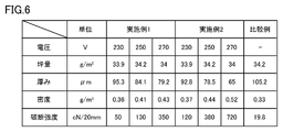
- FIG. 6 is a diagram showing evaluation conditions and evaluation results in Example 1, Example 2, and Comparative Example.
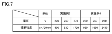
- FIG. 7 is a diagram showing evaluation conditions and evaluation results in Examples 3 and 4.
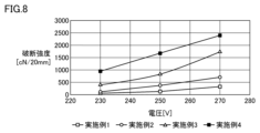
- FIG. 8 is a diagram showing the breaking strength in Examples 1 to 4.
- Example 1 In Example 1, first, a pellet-shaped liquid crystal polymer as a raw material liquid crystal polymer molded body was coarsely pulverized by putting it into a cutter mill device. In Example 1, a liquid crystal polymer having a melting point of 315° C. and an absorptance of 60% at a wavelength of 500 nm was used. A coarsely ground liquid crystal polymer was obtained by discharging the coarsely ground film-like liquid crystal polymer through a discharge hole having a diameter of 3 mm provided in a cutter mill device.
- the coarsely pulverized liquid crystal polymer was finely pulverized with a liquid nitrogen bead mill (LNM-08, manufactured by Aimex).
- a liquid nitrogen bead mill LNM-08, manufactured by Aimex.
- the vessel volume was set to 0.8 L
- zirconia beads with a diameter of 5 mm were used as media
- the amount of media was set to 500 mL
- 30 g of coarsely ground liquid crystal polymer was added, and the mixture was rotated.
- the pulverization treatment was performed at several 2000 rpm for 120 minutes.
- the coarsely pulverized liquid crystal polymer is dispersed in liquid nitrogen and wet pulverized.
- a granular finely pulverized liquid crystal polymer was obtained.
- the finely pulverized liquid crystal polymer was wet-classified with a mesh having an opening of 100 ⁇ m to remove coarse particles contained in the finely pulverized liquid crystal polymer, and the finely pulverized liquid crystal polymer that passed through the mesh was recovered.
- a mesh with an opening of 100 ⁇ m was used, but a mesh with an opening smaller than that of the mesh may be used for classification.
- the finely pulverized liquid crystal polymer from which coarse particles were removed was dispersed in a 20 wt% ethanol aqueous solution.
- the ethanol slurry in which the finely pulverized liquid crystal polymer was dispersed was crushed five times using a wet high-pressure crusher under the conditions of a nozzle diameter of 0.2 mm and a pressure of 200 MPa, thereby forming fibers.
- Starburst HJP-25060 manufactured by Sugino Machine was used as a wet high-pressure crusher. As a result, a liquid crystal polymer powder dispersed in an aqueous ethanol solution was obtained.
- liquid crystal polymer powder is mixed with 30 L of a 50 wt % ethanol aqueous solution. bottom.
- a rectangular sheet machine 2555 manufactured by Kumagai Riki Co., Ltd. was used as a paper machine, and a liquid crystal polymer powder dispersed in a dispersion medium was made on a microporous polyester mesh sheet having a pore size of 11 ⁇ m.
- the fiber mat 30 was formed on the microporous sheet by heating and drying at a temperature of 100° C. using a hot air dryer.
- the basis weight of the fiber mat 30 was about 35 g/m 2 .
- a plurality of fiber mats 30 were prepared, and the first main surface 31 of each fiber mat 30 was irradiated with light by changing the voltage conditions of the light irradiation device (PulseForge (registered trademark) 1300 manufactured by NovaCentrix).
- the voltages were 230 V, 250 V and 270 V, and the pulse length was 3.5 ms.
- the fiber mat 30 irradiated with light under these conditions is peeled off from the microporous sheet and measured using a thickness measuring device (digital linear gauge DG-525H (manufactured by Ono Seiki Co., Ltd.)), a density measuring device, or a tensile test. was carried out, and the basis weight, thickness, density, and breaking strength of the fiber mat 30 according to Example 1 were measured.
- a thickness measuring device digital linear gauge DG-525H (manufactured by Ono Seiki Co., Ltd.)
- a density measuring device or a tensile test.
- Example 1 the basis weight, thickness, density and breaking strength of the mat irradiated at 230 V were 33.9 g/m 2 , 95.3 ⁇ m, 0.36 g/m 3 and 50 cN/20 mm, respectively.
- Example 1 the basis weight, thickness, density and breaking strength of the mat irradiated at 250 V were 34.2 g/m 2 , 84.1 ⁇ m, 0.41 g/m 3 and 130 cN/20 mm, respectively.
- Example 1 the basis weight, thickness, density and breaking strength of the mat irradiated at 270 V were 34 g/m 2 , 79.2 ⁇ m, 0.43 g/m 3 and 350 cN/20 mm, respectively.
- Example 2 the fiber mat 30 was produced in substantially the same manner as in Example 1, and the same energy as in Example 1 was applied to the second main surface 32 located on the opposite side of the first main surface 31. irradiated with light. That is, in Example 2, the second main surface 32 was further irradiated with the light after the fiber mat 30 with the first main surface 31 irradiated with light was peeled off from the microporous sheet.
- the voltage of the light irradiation device (PulseForge (registered trademark) 1300 manufactured by NovaCentrix) when irradiating the second main surface 32 with light was 230 V, 250 V, and 270 V as in Example 1, and the pulse length was 3.5 ms. bottom.
- the basis weight, thickness, density, and breaking strength of the fiber mat 30 according to Example 2 were also measured in the same manner as in Example 1.
- Example 2 the basis weight, thickness, density, and breaking strength of the mat obtained by irradiating both the first principal surface 31 and the second principal surface 32 at 230 V were 33.9 g/m 2 , 92.8 ⁇ m, respectively. It was 0.37 g/m 3 and 120 cN/20 mm.
- Example 2 the basis weight, thickness, density, and breaking strength of the mat obtained by irradiating both the first principal surface 31 and the second principal surface 32 at 250 V were 34.2 g/m 2 , 78.5 ⁇ m, respectively. It was 0.44 g/m 3 and 380 cN/20 mm.
- Example 2 the basis weight, thickness, density, and breaking strength of the mat obtained by irradiating both the first main surface 31 and the second main surface 32 at 270 V were 34 g/m 2 , 65 ⁇ m, and 0.52 g/m 2 , respectively. m 3 , 720 cN/20 mm.
- Comparative Example differs from Example 1 in that the light irradiation step was omitted in the matting step. That is, in the fiber mat according to the comparative example, compared with the fiber mat 30 according to the first embodiment, the surface (first main surface) is not irradiated with light, and the fibers on the surface are not melted.
- the basis weight, thickness, density and breaking strength of the mat were 34.2 g/m 2 , 105.2 ⁇ m, 0.33 g/m 3 and 19.8 cN/20 mm, respectively.
- Example 3 In Example 3, a liquid crystal polymer having a melting point of 315° C. and an absorptance of 70% at a wavelength of 500 nm was used. A fiber mat 30 was obtained in substantially the same manner as in Example 1 except for the points described above.
- Example 3 the breaking strengths of the mats irradiated with light at 230 V, 250 V and 270 V were 400 cN/20 mm, 830 cN/20 mm and 1720 cN/20 mm, respectively.
- Example 4 In Example 4, a liquid crystal polymer having a melting point of 315° C. and an absorptance of 70% at a wavelength of 500 nm was used. A fiber mat 30 was obtained in substantially the same manner as in Example 2 except for the points described above.
- Example 4 the breaking strengths of the mats irradiated with light at 230 V, 250 V and 270 V were 930 cN/20 mm, 1690 cN/20 mm and 2410 cN/20 mm, respectively.
- each fiber mat 30 had sufficient strength (breaking strength) as compared with the comparative example. Moreover, it was confirmed that increasing the voltage during light irradiation increases the amount of the liquid crystal polymer powder to be fused, resulting in an increase in the density and breaking strength, although the thickness is reduced.
- the fine fibers are liquid crystal polymer powder, but the fine fibers are not limited to liquid crystal polymer powder.
- chemical fibers that do not have hydrogen bonds may be used as long as they have thermoplasticity.
- the support for making fine fibers is a microporous sheet
- the microporous sheet may be omitted and the papermaking wire 20 may be used as the support.
- fine fibers having a fiber length greater than the hole diameter of the papermaking wire 20 may be used, and the fiber length may be 200 ⁇ m or less.
- fibers having a fiber length of 1 mm or less may be used.
- microporous sheet 15 supply roller, 20 papermaking wire, 25, 26 transport roller, 30 fiber mat, 31 first main surface, 32 second main surface, 40 reservoir, 41 dispersion medium, 50 heating device, 60 light irradiation Equipment, 100 paper machine.
Landscapes
- Chemical & Material Sciences (AREA)
- Organic Chemistry (AREA)
- Engineering & Computer Science (AREA)
- Crystallography & Structural Chemistry (AREA)
- Materials Engineering (AREA)
- Chemical Kinetics & Catalysis (AREA)
- Health & Medical Sciences (AREA)
- Medicinal Chemistry (AREA)
- Polymers & Plastics (AREA)
- Textile Engineering (AREA)
- Nonwoven Fabrics (AREA)
- Paper (AREA)
Priority Applications (4)
| Application Number | Priority Date | Filing Date | Title |
|---|---|---|---|
| JP2023538267A JP7563608B2 (ja) | 2021-07-26 | 2022-03-25 | 繊維マットの製造方法 |
| CN202280051704.4A CN117716087A (zh) | 2021-07-26 | 2022-03-25 | 纤维毡的制造方法和纤维毡 |
| US18/414,784 US20240150655A1 (en) | 2021-07-26 | 2024-01-17 | Method for manufacturing fiber mat, and fiber mat |
| JP2024163326A JP7743902B2 (ja) | 2021-07-26 | 2024-09-20 | 繊維マット |
Applications Claiming Priority (2)
| Application Number | Priority Date | Filing Date | Title |
|---|---|---|---|
| JP2021121191 | 2021-07-26 | ||
| JP2021-121191 | 2021-07-26 |
Related Child Applications (1)
| Application Number | Title | Priority Date | Filing Date |
|---|---|---|---|
| US18/414,784 Continuation US20240150655A1 (en) | 2021-07-26 | 2024-01-17 | Method for manufacturing fiber mat, and fiber mat |
Publications (1)
| Publication Number | Publication Date |
|---|---|
| WO2023007847A1 true WO2023007847A1 (ja) | 2023-02-02 |
Family
ID=85087848
Family Applications (1)
| Application Number | Title | Priority Date | Filing Date |
|---|---|---|---|
| PCT/JP2022/014614 Ceased WO2023007847A1 (ja) | 2021-07-26 | 2022-03-25 | 繊維マットの製造方法および繊維マット |
Country Status (4)
| Country | Link |
|---|---|
| US (1) | US20240150655A1 (https=) |
| JP (2) | JP7563608B2 (https=) |
| CN (1) | CN117716087A (https=) |
| WO (1) | WO2023007847A1 (https=) |
Cited By (1)
| Publication number | Priority date | Publication date | Assignee | Title |
|---|---|---|---|---|
| WO2025187278A1 (ja) * | 2024-03-08 | 2025-09-12 | 株式会社村田製作所 | 多孔質構造体 |
Citations (5)
| Publication number | Priority date | Publication date | Assignee | Title |
|---|---|---|---|---|
| JPS53111120A (en) * | 1977-03-07 | 1978-09-28 | Asahi Chem Ind Co Ltd | Production of pulp-like particle |
| JPS60239600A (ja) * | 1984-05-11 | 1985-11-28 | ヘキスト・セラニーズ・コーポレーション | サ−モトロピツク液晶ポリマ−のフイブリルよりなる高性能紙 |
| JPS6335816A (ja) * | 1986-07-25 | 1988-02-16 | Marubeni Kk | 熱可塑性液晶ポリマ−ミクロフイブリツドの製造法 |
| JP2006089872A (ja) * | 2004-09-24 | 2006-04-06 | Japan Vilene Co Ltd | 不織布の製造方法 |
| WO2021060255A1 (ja) * | 2019-09-25 | 2021-04-01 | 株式会社村田製作所 | 液晶ポリマーパウダーおよびその製造方法 |
Family Cites Families (7)
| Publication number | Priority date | Publication date | Assignee | Title |
|---|---|---|---|---|
| EP0167682A1 (en) * | 1984-05-02 | 1986-01-15 | Celanese Corporation | High performance papers comprised of fibrils of thermotropic liquid crystal polymers |
| JP2690391B2 (ja) * | 1990-09-21 | 1997-12-10 | 株式会社クラレ | 嵩高性不織布およびその製造法 |
| JP4746226B2 (ja) * | 2001-09-27 | 2011-08-10 | 日本バイリーン株式会社 | 印刷基材用不織布 |
| JP4584702B2 (ja) * | 2004-12-24 | 2010-11-24 | 日本バイリーン株式会社 | 不織布及び不織布の製造方法、並びに不織布を用いた電気二重層キャパシタ用セパレータ、リチウムイオン二次電池用セパレータ、電気二重層キャパシタ又はリチウムイオン二次電池 |
| JP5311120B2 (ja) * | 2009-02-19 | 2013-10-09 | アイシン精機株式会社 | 順送プレス装置 |
| JP2013159882A (ja) * | 2012-02-07 | 2013-08-19 | Japan Vilene Co Ltd | 繊維シート |
| JP6350774B1 (ja) * | 2016-11-16 | 2018-07-04 | 三菱瓦斯化学株式会社 | 成形品の製造方法 |
-
2022
- 2022-03-25 WO PCT/JP2022/014614 patent/WO2023007847A1/ja not_active Ceased
- 2022-03-25 JP JP2023538267A patent/JP7563608B2/ja active Active
- 2022-03-25 CN CN202280051704.4A patent/CN117716087A/zh active Pending
-
2024
- 2024-01-17 US US18/414,784 patent/US20240150655A1/en active Pending
- 2024-09-20 JP JP2024163326A patent/JP7743902B2/ja active Active
Patent Citations (5)
| Publication number | Priority date | Publication date | Assignee | Title |
|---|---|---|---|---|
| JPS53111120A (en) * | 1977-03-07 | 1978-09-28 | Asahi Chem Ind Co Ltd | Production of pulp-like particle |
| JPS60239600A (ja) * | 1984-05-11 | 1985-11-28 | ヘキスト・セラニーズ・コーポレーション | サ−モトロピツク液晶ポリマ−のフイブリルよりなる高性能紙 |
| JPS6335816A (ja) * | 1986-07-25 | 1988-02-16 | Marubeni Kk | 熱可塑性液晶ポリマ−ミクロフイブリツドの製造法 |
| JP2006089872A (ja) * | 2004-09-24 | 2006-04-06 | Japan Vilene Co Ltd | 不織布の製造方法 |
| WO2021060255A1 (ja) * | 2019-09-25 | 2021-04-01 | 株式会社村田製作所 | 液晶ポリマーパウダーおよびその製造方法 |
Cited By (1)
| Publication number | Priority date | Publication date | Assignee | Title |
|---|---|---|---|---|
| WO2025187278A1 (ja) * | 2024-03-08 | 2025-09-12 | 株式会社村田製作所 | 多孔質構造体 |
Also Published As
| Publication number | Publication date |
|---|---|
| CN117716087A (zh) | 2024-03-15 |
| JP7563608B2 (ja) | 2024-10-08 |
| JP2024166409A (ja) | 2024-11-28 |
| JPWO2023007847A1 (https=) | 2023-02-02 |
| JP7743902B2 (ja) | 2025-09-25 |
| US20240150655A1 (en) | 2024-05-09 |
Similar Documents
| Publication | Publication Date | Title |
|---|---|---|
| US20230002548A1 (en) | Liquid crystal polymer film and method of producing the liquid crystal polymer film | |
| JP7405146B2 (ja) | 液晶ポリマーパウダーおよびその製造方法 | |
| JP7743902B2 (ja) | 繊維マット | |
| JPS61160500A (ja) | 高密度パラアラミド紙 | |
| KR102110215B1 (ko) | 초지용 원료의 제조 방법, 얻어진 초지용 원료, 및 그 원료를 사용한 내열성 전기 절연 시트 재료 | |
| US20230416987A1 (en) | Method for producing fiber mat and fiber mat | |
| US20250092605A1 (en) | Liquid crystal polymer powder, liquid crystal polymer film, and method of producing same | |
| US20240182784A1 (en) | Porous body and method for manufacturing porous body | |
| JP3536433B2 (ja) | 古紙ボードの製造方法 | |
| JPH09220709A (ja) | 古紙ボード | |
| JP7673839B2 (ja) | 液晶ポリマーペレット、液晶ポリマーパウダー、液晶ポリマーフィルム、および、それらの製造方法 | |
| US20260091571A1 (en) | Laminated film and method for producing laminated film | |
| JPWO2023007847A5 (ja) | 繊維マットの製造方法 | |
| JP6963954B2 (ja) | 湿式不織布の製造方法 | |
| JP7609288B2 (ja) | 液晶ポリマーフィルムおよび液晶ポリマーフィルムの製造方法 | |
| KR102030661B1 (ko) | 건조 슬러지의 재활용 방법 및 이를 이용한 종이 | |
| JP2022111604A (ja) | 繊維構造体製造装置、繊維構造体製造方法、繊維構造体 | |
| CN120936765A (zh) | 非织造织物、电极组件、其制造方法、以及实行所述制造方法的设备 | |
| JP2022111606A (ja) | 繊維構造体製造装置、繊維構造体製造方法、繊維構造体 | |
| WO2024029207A1 (ja) | 液晶ポリマーフィルムおよびこれを備えた積層体、ならびに、液晶ポリマーフィルムの製造方法 | |
| JPH10325065A (ja) | 不織布及びその製造方法とプリント配線基板 | |
| JP2006334457A (ja) | フィルターメディア及びその製造方法 |
Legal Events
| Date | Code | Title | Description |
|---|---|---|---|
| 121 | Ep: the epo has been informed by wipo that ep was designated in this application |
Ref document number: 22848931 Country of ref document: EP Kind code of ref document: A1 |
|
| WWE | Wipo information: entry into national phase |
Ref document number: 2023538267 Country of ref document: JP |
|
| WWE | Wipo information: entry into national phase |
Ref document number: 202280051704.4 Country of ref document: CN |
|
| NENP | Non-entry into the national phase |
Ref country code: DE |
|
| 122 | Ep: pct application non-entry in european phase |
Ref document number: 22848931 Country of ref document: EP Kind code of ref document: A1 |