WO2023007820A1 - 質量分析装置 - Google Patents
質量分析装置 Download PDFInfo
- Publication number
- WO2023007820A1 WO2023007820A1 PCT/JP2022/011509 JP2022011509W WO2023007820A1 WO 2023007820 A1 WO2023007820 A1 WO 2023007820A1 JP 2022011509 W JP2022011509 W JP 2022011509W WO 2023007820 A1 WO2023007820 A1 WO 2023007820A1
- Authority
- WO
- WIPO (PCT)
- Prior art keywords
- chamber
- mass spectrometer
- plasma
- gas
- additional gas
- Prior art date
- Legal status (The legal status is an assumption and is not a legal conclusion. Google has not performed a legal analysis and makes no representation as to the accuracy of the status listed.)
- Ceased
Links
Images




Classifications
-
- H—ELECTRICITY
- H01—ELECTRIC ELEMENTS
- H01J—ELECTRIC DISCHARGE TUBES OR DISCHARGE LAMPS
- H01J49/00—Particle spectrometers or separator tubes
- H01J49/02—Details
- H01J49/24—Vacuum systems, e.g. maintaining desired pressures
-
- H—ELECTRICITY
- H01—ELECTRIC ELEMENTS
- H01J—ELECTRIC DISCHARGE TUBES OR DISCHARGE LAMPS
- H01J49/00—Particle spectrometers or separator tubes
- H01J49/02—Details
- H01J49/10—Ion sources; Ion guns
- H01J49/105—Ion sources; Ion guns using high-frequency excitation, e.g. microwave excitation, Inductively Coupled Plasma [ICP]
-
- H—ELECTRICITY
- H01—ELECTRIC ELEMENTS
- H01J—ELECTRIC DISCHARGE TUBES OR DISCHARGE LAMPS
- H01J49/00—Particle spectrometers or separator tubes
- H01J49/02—Details
- H01J49/04—Arrangements for introducing or extracting samples to be analysed, e.g. vacuum locks; Arrangements for external adjustment of electron- or ion-optical components
- H01J49/0422—Arrangements for introducing or extracting samples to be analysed, e.g. vacuum locks; Arrangements for external adjustment of electron- or ion-optical components for gaseous samples
Definitions
- the present disclosure relates to mass spectrometers.
- a sample is ionized by being introduced into the plasma of an ion source, and the ionized sample passes through a first chamber containing a sampling cone and a skimmer cone and a second chamber containing a collision cell. It is passed through and introduced into a third chamber containing a mass spectrometer.
- the first chamber is evacuated mainly by a roughing pump, and the second and third chambers are evacuated by turbomolecular pumps.
- reaction gas with a small molecular weight is introduced into the collision cell placed in the second chamber in order to remove interfering ions that have entered from the ion source and interfere with the target element in mass-to-charge ratio.
- reaction gas hydrogen gas containing helium or the like or hydrogen gas not containing helium is used.
- a turbo-molecular pump is a type of mechanical vacuum pump in which a rotor, which is a rotating body with metal turbine blades, rotates at high speed, ejecting gas by ejecting gas molecules. Because of this structure, turbomolecular pumps are not suitable for guiding molecules that are light in mass and move at high speed in a predetermined direction, and it is known that the pumping performance of hydrogen gas with a small molecular weight is reduced. It is
- Patent Document 1 discloses a technique for introducing additional gas from a position closer to the exhaust side end of the turbo molecular pump in order to reduce the partial pressure of hydrogen gas at the exhaust side end of the turbo molecular pump when a large amount of hydrogen gas is introduced. is disclosed.
- the additional gas since the additional gas is directly introduced into the turbo-molecular pump, the additional gas can only be introduced at a flow rate equal to or less than the exhaust gas amount of the turbo-molecular pump. . Further, in the technology disclosed in Patent Document 1, the additional gas acts to suppress the rotational motion of the rotor of the turbo-molecular pump, so the hydrogen gas exhaust performance cannot be further improved.
- the present disclosure has been made to solve such problems, and the purpose thereof is to provide a mass spectrometer capable of improving the exhaust performance of hydrogen gas.
- the present disclosure relates to a mass spectrometer that performs mass spectrometry by lighting plasma and ionizing a sample.
- the mass spectrometer includes a roughing pump, a turbo-molecular pump, a first chamber evacuated by the roughing pump, a second chamber positioned after the first chamber and into which hydrogen gas is introduced, and a second A third chamber located after the chambers and provided with a mass spectrometer, a first flow path forming an exhaust flow from the first chamber to the roughing pump, and a turbomolecular pump from the second and third chambers a second flow path for providing an exhaust flow to the first flow path.
- the mass spectrometer introduces an additional gas having a higher molecular weight than the hydrogen gas into the second channel.
- FIG. 1 is a diagram showing a schematic configuration of a mass spectrometer according to Embodiment 1; FIG. It is a figure which shows schematic structure of the mass spectrometer based on a comparative example.
- 4 is a graph showing the relationship between the amount of hydrogen gas introduced and the degree of vacuum when plasma is turned off. 4 is a graph showing the relationship between the amount of hydrogen gas introduced and the degree of vacuum during plasma lighting.
- 10 is a flow chart showing processing executed by a control device in a mass spectrometer according to Embodiment 2.
- FIG. 1 is a diagram showing a schematic configuration of a mass spectrometer 1 according to Embodiment 1.
- the mass spectrometer 1 includes a plasma torch 15 , a main body 20 , a roughing pump 30 , a turbomolecular pump 40 , a vacuum gauge 90 , a valve 50 and a controller 10 .
- the plasma torch 15 ionizes the sample.
- the plasma torch 15 includes a sample tube, a plasma gas tube, a cooling gas tube, and a high frequency induction coil (not shown).
- the plasma gas pipe is connected to a gas supply source 16 and supplied with argon gas or the like.
- a plasma P is generated in the plasma torch 15 by the operation of the high frequency induction coil.
- the main body 20 has a structure partitioned by a sampling cone 71 and a skimmer cone 72 from the plasma torch 15 side. A part of the plasma P generated by the plasma torch 15 becomes an ion beam through the sampling cone 71 and the skimmer cone 72 .
- the main body 20 includes three chambers, a first chamber 21, a second chamber 22 and a third chamber 23, which can communicate with each other.
- First chamber 21 includes a space sandwiched between sampling cone 71 and skimmer cone 72 .
- Part of the plasma P that has passed through the orifice 71 a of the sampling cone 71 enters the first chamber 21 .
- a portion of the plasma P passes through the orifice 72a of the skimmer cone 72 and is guided to a subsequent stage in the form of an ion beam.
- behind the skimmer cone 72 are ion optics for guiding the ion beam.
- the first chamber 21 is configured to be evacuated by a roughing vacuum pump 30 via an exhaust pipe 61 as a first flow path.
- a roughing vacuum pump 30 for example, an oil rotary pump is used.
- a second chamber 22 separated from the first chamber 21 by a gate valve 73 is provided in the rear stage of the first chamber 21 .
- a cell 14 is arranged in the second chamber 22 .
- the cell 14 removes from the ion beam extracted through the orifice 72a of the skimmer cone 72 polyatomic molecular ions whose mass-to-charge ratio interferes with the element of interest.
- the cell 14 undergoes reactions therein, such as charge transfer reactions, with the molecules of the reactant gas.
- Hydrogen gas for example, is used as the reaction gas.
- a reactant gas is introduced through an inlet at the top of the cell 14 .
- the cell 14 includes a multipole electrode and the like.
- a third chamber 23 separated from the second chamber 22 by a partition wall 74 is provided.
- a separation section for extracting ions having a predetermined mass-to-charge ratio is provided in the third chamber 23 .
- the separating section is composed of a multipole electrode 81 such as a quadrupole.
- a detector 82 for detecting the extracted ions is arranged behind the multipole electrode 81 in the third chamber 23 .
- the detector 82 functions as a mass spectrometer that outputs detection signals to a signal processing device (not shown) provided outside the main body 20 .
- Both the second chamber 22 and the third chamber 23 are evacuated by a turbomolecular pump 40 .
- the turbo-molecular pump 40 has a plurality of rotor blades inside.
- the exhaust side of the turbomolecular pump 40 extends toward the roughing pump 30 via an exhaust pipe 62 as a second flow path and is coupled to the exhaust pipe 61 .
- a position A is a position where the exhaust pipe 61 and the exhaust pipe 62 intersect.
- Additional gas is introduced into the exhaust pipe 62 via the valve 50 . Additional gas is introduced into exhaust pipe 62 from a gas source (not shown) through intake pipe 64 , valve 50 and intake pipe 63 . A position where the exhaust pipe 62 and the intake pipe 63 intersect is referred to as a position B. As shown in FIG.
- the valve 50 functions as a valve that adjusts the flow rate of the additional gas introduced from the intake pipe 64 to the intake pipe 63 . Since the exhaust pipe 62 of the turbomolecular pump 40 is in a decompressed state, a certain amount of additional gas is introduced into the exhaust pipe 62 when the valve 50 is opened.
- the valve 50 may be, for example, a needle valve capable of controlling minute flow rates.
- the additional gas atmospheric component gases that do not contain molecules with a small molecular weight such as hydrogen gas, argon gas, nitrogen gas, helium gas, etc. can be used.
- the additional gas a mixture of two or more of these gases may be used. The introduction of the additional gas continues while the plasma P is on and the analysis is performed.
- the vacuum gauge 90 is connected to the exhaust pipe 61, which is the first flow path.
- a Pirani gauge is used, which utilizes a phenomenon in which the amount of heat radiation from a metal wire that is electrically heated in a vacuum changes with pressure, and the electrical resistance changes.
- the control device 10 includes a CPU (Central Processing Unit) 11 and a memory 12, for example.
- the memory 12 is composed of, for example, a ROM (Read Only Memory) and a RAM (Random Access Memory), and can store various data in addition to the control program.
- the CPU 11 executes a control program stored in the memory 12 to control operations such as introduction of reaction gas and additional gas.
- FIG. 2 is a diagram showing a schematic configuration of a mass spectrometer 1A according to a comparative example.
- the mass spectrometer 1A of FIG. 2 differs from the mass spectrometer 1 of FIG. 1 in the introduction position of the additional gas, and the rest of the configuration is the same.
- the same components as those of the mass spectrometer 1 of FIG. 1 are denoted by the same reference numerals, and detailed description thereof will not be repeated.
- reaction gas is introduced into the cell 14 as necessary.
- the reaction gas for example, a gas containing hydrogen is used.
- Molecules of low molecular weight gas such as hydrogen gas diffuse outside the cell 14 in the second chamber 22 and may also diffuse into the third chamber 23 .
- the second chamber 22 and the third chamber 23 are depressurized via the turbomolecular pump 40, but the turbomolecular pump 40 is limited in its performance when exhausting gas with a small molecular weight.
- FIG. 3 is a graph showing the relationship between the amount of hydrogen gas introduced and the degree of vacuum when the plasma is turned off
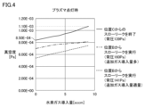
- FIG. 4 is a graph showing the relationship between the amount of hydrogen gas introduced and the degree of vacuum when the plasma is turned on.
- FIG. 3 and 4 show the relationship between the amount of hydrogen gas introduced and the degree of vacuum when the additional gas is introduced from positions corresponding to position B in FIG. 1 and position C in FIG. 3 and 4, the horizontal axis indicates the amount of hydrogen gas introduced [sccm], and the vertical axis indicates the degree of vacuum [Pa].
- the case of performing slow leak from position C is indicated by a solid line
- the case of performing slow leak from position B is indicated by a broken line.
- FIG. 4 the case where the slow leak from position C ends is indicated by a solid line
- the case where the slow leak from position B is performed and the amount of additional gas introduced is large is indicated by a dashed line
- the slow leak from position B is indicated by a dashed line.
- a dashed line indicates the case where the amount of additional gas introduced is appropriate when executing .
- Position B is a position close to the exhaust side of the turbo-molecular pump 40, so that the hydrogen gas remaining on the exhaust side can be swept away.
- the swept hydrogen gas flows to the roughing pump 3 without going against the exhaust flow from the first chamber 21 to the roughing pump 3 when passing through the position A where the exhaust pipe 61 and the exhaust pipe 62 intersect. Therefore, the exhaust gas compressed by the turbo-molecular pump 40 efficiently flows toward the roughing pump 30 side without stagnation due to the slow leak from the position B, without causing stagnation in the hydrogen gas flow. Thereby, the mass spectrometer 1 can improve the exhaust performance of the hydrogen gas.
- the mass spectrometer 1A that performs slow leak at position C when the oil rotary pump is used as the roughing pump 30, the phenomenon in which the oil reversely diffuses and enters the exhaust pipe from the roughing pump 30 is prevented. Prevent by slow leak. Furthermore, the roughing pump 30 may vibrate due to the operation of the rotating parts when no load is applied.
- the mass spectrometer 1A can suppress the operation of the rotating part by applying a load to the roughing pump 30 due to the slow leak, and can prevent noise due to vibration.
- the degree of vacuum deteriorates from 8.50 ⁇ 10 ⁇ 4 [Pa] to 1.10 ⁇ 10 ⁇ 3 [Pa]. do.
- the back pressure of the turbo molecular pump 40 at this time is 139 [Pa].
- the state of the degree of vacuum is maintained higher than that from the position C.
- the back pressure of the turbo molecular pump 40 at this time is 160 [Pa].
- the back pressure of the turbo molecular pump 40 at this time is 141 [Pa].
- FIG. Position B is a position close to the exhaust side of the turbo-molecular pump 40, so that the hydrogen gas remaining on the exhaust side can be swept away. The swept hydrogen gas flows to the roughing pump 3 without going against the exhaust flow from the first chamber 21 to the roughing pump 3 when passing through the position A where the exhaust pipe 61 and the exhaust pipe 62 intersect.
- the exhaust gas compressed by the turbo-molecular pump 40 efficiently flows toward the roughing pump 30 side without stagnation due to the slow leak from the position B, without causing stagnation in the hydrogen gas flow.
- the mass spectrometer 1 can improve the exhaust performance of the hydrogen gas.
- the compression ratio of the turbo-molecular pump 40 is low because the back pressure of the turbo-molecular pump 40 is higher than when the flow rate of the additional gas is appropriate. Therefore, the degree of vacuum in the high vacuum region of the third chamber 23 is lowered.
- the back pressure of the turbo-molecular pump 40 is suppressed by introducing an appropriate amount of additional gas from the position B when the plasma is turned on. can. Thereby, the mass spectrometer 1 can improve the exhaust performance of the hydrogen gas.
- the mass spectrometer 1 can improve the hydrogen gas exhaust performance by slowly leaking the additional gas at the optimum introduction position when the plasma is turned off and when the plasma is turned on. This is more effective and economical than replacing the roughing pump 30 with a pump having high exhaust performance such as a dry pump.
- FIG. 5 is a flow chart showing processing executed by the control device 10 in the mass spectrometer according to the second embodiment.
- the control device 10 first determines whether or not the plasma is being lit based on the operating state of the plasma torch 15 (step S1). When the control device 10 determines that the plasma is being extinguished (NO in step S1), it opens the electronic control valve and executes slow leak (step S2). Then, the control device 10 returns the processing to the main routine. On the other hand, when the control device 10 determines that the plasma is being lit (YES in step S1), it closes the electronic control valve and ends the slow leak (step S3). Then, the control device 10 returns the processing to the main routine.
- the control device 10 opens the electronic control valve to perform slow leaking. Noise of the roughing pump 30 can be prevented.
- the introduction of the plasma gas from the sampling cone 71 can prevent oil from entering the exhaust pipe from the roughing pump 30 and noise to some extent, so that the slow leak can be terminated.
- FIG. 6 is a diagram showing a schematic configuration of a mass spectrometer 1B according to Embodiment 3. As shown in FIG. The mass spectrometer 1B of FIG. 6 has a configuration in which the valve 50 in the mass spectrometer 1 of FIG. 1 is replaced with a three-way valve 51, and other configurations are the same.
- the same components as those of the mass spectrometer 1 of FIG. 1 are denoted by the same reference numerals, and detailed description thereof will not be repeated.
- the three-way valve 51 is configured to switch the flow path connected to the intake pipe 63 between the first intake pipe 65 and the second intake pipe 66 .
- Additional gas passes from a gas source (not shown) through the first intake pipe 65 or the second intake pipe 66 , the three-way valve 51 , and then the intake pipe 63 to be introduced into the exhaust pipe 62 .
- the first intake pipe 65 has a smaller inner diameter than the second intake pipe 66 . Therefore, the amount of additional gas introduced into the intake pipe 63 from the first intake pipe 65 is smaller than the amount of additional gas introduced into the intake pipe 63 from the second intake pipe 66 .
- FIG. 7 is a flowchart showing processing executed by the control device 10 in the mass spectrometer 1B according to the third embodiment.
- the control device 10 first determines whether or not the plasma is being lit based on the operating state of the plasma torch 15 (step S11). When the control device 10 determines that the plasma is being extinguished (NO in step S11), it controls the three-way valve 51 to switch the second intake pipe 66 to communicate with the intake pipe 63 (step S12). Then, the control device 10 returns the processing to the main routine. This increases the amount of additional gas introduced into the intake pipe 63 .
- control device 10 determines that the plasma is being lit (YES in step S11), it controls the three-way valve 51 to switch the first intake pipe 65 to communicate with the intake pipe 63 (step S13). Then, the control device 10 returns the processing to the main routine. This reduces the amount of additional gas introduced into the intake pipe 63 .
- the load on the roughing pump 30 is increased by increasing the amount of the additional gas introduced into the intake pipe 63, and the phenomenon of oil entering the exhaust pipe from the roughing pump 30 is suppressed by the additional gas. can be prevented by the pressure of Furthermore, when the plasma is extinguished, the additional gas is increased, so noise can be prevented by applying a load to the roughing pump 30, which generates noise due to vibration or the like when no load is applied.
- the back pressure of the turbo-molecular pump 40 is lowered. As a result, the degree of vacuum in the high vacuum region of the third chamber 23 can be improved by improving the compression ratio of the turbo-molecular pump 40 .
- a mass spectrometer performs mass spectrometry by turning on plasma and ionizing a sample.
- the mass spectrometer includes a roughing pump, a turbo-molecular pump, a first chamber evacuated by the roughing pump, a second chamber positioned after the first chamber and into which hydrogen gas is introduced, and a second A third chamber located after the chambers and provided with a mass spectrometer, a first flow path forming an exhaust flow from the first chamber to the roughing pump, and a turbomolecular pump from the second and third chambers a second flow path for providing an exhaust flow to the first flow path.
- the mass spectrometer introduces an additional gas having a higher molecular weight than the hydrogen gas into the second channel.
- the mass spectrometer described in item 1 since the additional gas having a molecular weight larger than that of the hydrogen gas is introduced into the second flow path, even when a large amount of hydrogen gas is introduced, the exhaust flow of the viscous flow is reduced to the second flow path. It can be formed on two channels. Therefore, in the mass spectrometer 1, the exhaust gas compressed by the turbomolecular pump efficiently flows to the roughing pump side without stagnation. Thereby, the mass spectrometer 1 can improve the exhaust performance of the hydrogen gas.
- (Section 2) further includes a valve for adjusting the flow rate of the additional gas introduced into the second flow path.
- the valve is set to an opening smaller than the maximum opening when the plasma is turned on and when the plasma is turned off.
- the hydrogen gas exhaust performance can be improved by slowly leaking the additional gas at the optimum introduction position when the plasma is turned off and when the plasma is turned on.
- (Section 3) further includes a valve for adjusting the flow rate of the additional gas introduced into the second flow path.
- the valve is closed when the plasma is turned on and opened when the plasma is turned off.
- (Section 4) further includes a valve for adjusting the flow rate of the additional gas introduced into the second flow path.
- the additional gas flow introduced by the valve when the plasma is turned on is less than the additional gas flow introduced by the valve when the plasma is turned off.
- the additional gas is increased when the plasma is turned off, the phenomenon of oil entering the exhaust pipe from the roughing pump can be prevented by the pressure of the additional gas. Furthermore, when the plasma is extinguished, the additional gas is increased, so noise can be prevented by applying a load to the roughing pump, which generates noise due to vibration or the like when no load is applied. On the other hand, when the plasma is turned on, the flow rate of the additional gas is reduced, so the back pressure of the turbomolecular pump is lowered. As a result, the degree of vacuum in the high vacuum region of the third chamber can be improved by improving the compression ratio of the turbomolecular pump.
- the flow rate of the additional gas introduced into the second flow path during plasma lighting is in the range from 0.5 sccm to 0.05 slm.
- the mass spectrometer according to item 5 it is possible to prevent the degree of vacuum in the high vacuum region of the third chamber from lowering, and to prevent the phenomenon of oil entering the exhaust pipe from the roughing pump. can.
- the additional gas is a gas having atmospheric components, nitrogen gas, argon gas, helium gas, or a mixture of at least two of them.
Landscapes
- Chemical & Material Sciences (AREA)
- Analytical Chemistry (AREA)
- Physics & Mathematics (AREA)
- Engineering & Computer Science (AREA)
- Plasma & Fusion (AREA)
- Other Investigation Or Analysis Of Materials By Electrical Means (AREA)
Priority Applications (4)
| Application Number | Priority Date | Filing Date | Title |
|---|---|---|---|
| CN202280051888.4A CN117897796A (zh) | 2021-07-30 | 2022-03-15 | 质量分析装置 |
| JP2023538251A JP7544279B2 (ja) | 2021-07-30 | 2022-03-15 | 質量分析装置 |
| US18/292,897 US20240363324A1 (en) | 2021-07-30 | 2022-03-15 | Mass spectrometer |
| EP22848904.3A EP4379769A4 (en) | 2021-07-30 | 2022-03-15 | MASS SPECTROMETER |
Applications Claiming Priority (2)
| Application Number | Priority Date | Filing Date | Title |
|---|---|---|---|
| JP2021125039 | 2021-07-30 | ||
| JP2021-125039 | 2021-07-30 |
Publications (1)
| Publication Number | Publication Date |
|---|---|
| WO2023007820A1 true WO2023007820A1 (ja) | 2023-02-02 |
Family
ID=85087786
Family Applications (1)
| Application Number | Title | Priority Date | Filing Date |
|---|---|---|---|
| PCT/JP2022/011509 Ceased WO2023007820A1 (ja) | 2021-07-30 | 2022-03-15 | 質量分析装置 |
Country Status (5)
| Country | Link |
|---|---|
| US (1) | US20240363324A1 (https=) |
| EP (1) | EP4379769A4 (https=) |
| JP (1) | JP7544279B2 (https=) |
| CN (1) | CN117897796A (https=) |
| WO (1) | WO2023007820A1 (https=) |
Cited By (1)
| Publication number | Priority date | Publication date | Assignee | Title |
|---|---|---|---|---|
| GB2632683A (en) * | 2023-08-17 | 2025-02-19 | Thermo Fisher Scient Bremen Gmbh | Mass spectrometer comprising a vacuum system and a method of operation |
Families Citing this family (1)
| Publication number | Priority date | Publication date | Assignee | Title |
|---|---|---|---|---|
| US20240363324A1 (en) * | 2021-07-30 | 2024-10-31 | Shimadzu Corporation | Mass spectrometer |
Citations (5)
| Publication number | Priority date | Publication date | Assignee | Title |
|---|---|---|---|---|
| JPH0727089A (ja) * | 1993-07-07 | 1995-01-27 | Osaka Shinku Kiki Seisakusho:Kk | 真空ポンプ装置 |
| JP2007538197A (ja) * | 2004-05-21 | 2007-12-27 | ザ ビーオーシー グループ ピーエルシー | ポンピング装置 |
| JP2008095504A (ja) * | 2006-10-05 | 2008-04-24 | Agilent Technol Inc | 分析装置 |
| JP2013143196A (ja) * | 2012-01-06 | 2013-07-22 | Agilent Technologies Inc | 誘導結合プラズマms/ms型質量分析装置 |
| CN111128671A (zh) * | 2019-11-19 | 2020-05-08 | 清华大学 | 质谱仪气压调节系统及方法 |
Family Cites Families (21)
| Publication number | Priority date | Publication date | Assignee | Title |
|---|---|---|---|---|
| JP2507518B2 (ja) * | 1988-02-29 | 1996-06-12 | 株式会社日立製作所 | 真空排気装置 |
| WO1993013241A1 (en) * | 1991-12-23 | 1993-07-08 | Genus, Inc. | Purge gas in wafer coating area selection |
| DE102007027352A1 (de) * | 2007-06-11 | 2008-12-18 | Oerlikon Leybold Vacuum Gmbh | Massenspektrometer-Anordnung |
| SG183179A1 (en) * | 2010-02-26 | 2012-09-27 | Perkinelmer Health Sci Inc | Plasma mass spectrometry with ion suppression |
| JP5497615B2 (ja) * | 2010-11-08 | 2014-05-21 | 株式会社日立ハイテクノロジーズ | 質量分析装置 |
| WO2014191746A1 (en) * | 2013-05-31 | 2014-12-04 | Micromass Uk Limited | Compact mass spectrometer |
| EP3027989B1 (en) * | 2013-07-30 | 2018-02-28 | Board of Regents, The University of Texas System | Sample transfer to high vacuum transition flow |
| GB201314841D0 (en) * | 2013-08-20 | 2013-10-02 | Thermo Fisher Scient Bremen | Multiple port vacuum pump system |
| US10416131B2 (en) * | 2014-03-31 | 2019-09-17 | Leco Corporation | GC-TOF MS with improved detection limit |
| FR3019298B1 (fr) * | 2014-03-31 | 2016-04-15 | Horiba Jobin Yvon Sas | Procede et appareil de mesure d'un echantillon solide organique par spectrometrie de decharge luminescente |
| US10290482B1 (en) * | 2018-03-13 | 2019-05-14 | Agilent Technologies, Inc. | Tandem collision/reaction cell for inductively coupled plasma-mass spectrometry (ICP-MS) |
| US10854438B2 (en) * | 2018-03-19 | 2020-12-01 | Agilent Technologies, Inc. | Inductively coupled plasma mass spectrometry (ICP-MS) with improved signal-to-noise and signal-to-background ratios |
| GB2572819B (en) * | 2018-04-13 | 2021-05-19 | Thermo Fisher Scient Bremen Gmbh | Method and apparatus for operating a vacuum interface of a mass spectrometer |
| US11075066B2 (en) * | 2018-10-26 | 2021-07-27 | Agilent Technologies, Inc. | Automated detection of nanoparticles using single-particle inductively coupled plasma mass spectrometry (SP-ICP-MS) |
| JP7396237B2 (ja) * | 2020-09-15 | 2023-12-12 | 株式会社島津製作所 | 質量分析装置 |
| US20240363324A1 (en) * | 2021-07-30 | 2024-10-31 | Shimadzu Corporation | Mass spectrometer |
| EP4435426A4 (en) * | 2021-11-17 | 2025-03-12 | Shimadzu Corporation | INDUCTIVELY COUPLED PLASMA MASS SPECTROMETER |
| US20250275050A1 (en) * | 2022-04-22 | 2025-08-28 | Standard Biotools Canada Inc. | Sealed Plasma Torch |
| JP2024064401A (ja) * | 2022-10-28 | 2024-05-14 | 株式会社島津製作所 | 質量分析装置 |
| DE202023102071U1 (de) * | 2023-04-20 | 2023-06-12 | Thermo Fisher Scientific (Bremen) Gmbh | Massenspektrometriesystem zur Bestimmung eines Maßes für eine Abfallrate |
| US20250308877A1 (en) * | 2024-04-01 | 2025-10-02 | Kimia Analytics Inc. | Hybrid inductively coupled plasma mass spectrometer (icp-ms) and methods |
-
2022
- 2022-03-15 US US18/292,897 patent/US20240363324A1/en active Pending
- 2022-03-15 CN CN202280051888.4A patent/CN117897796A/zh active Pending
- 2022-03-15 WO PCT/JP2022/011509 patent/WO2023007820A1/ja not_active Ceased
- 2022-03-15 EP EP22848904.3A patent/EP4379769A4/en active Pending
- 2022-03-15 JP JP2023538251A patent/JP7544279B2/ja active Active
Patent Citations (6)
| Publication number | Priority date | Publication date | Assignee | Title |
|---|---|---|---|---|
| JPH0727089A (ja) * | 1993-07-07 | 1995-01-27 | Osaka Shinku Kiki Seisakusho:Kk | 真空ポンプ装置 |
| JP2007538197A (ja) * | 2004-05-21 | 2007-12-27 | ザ ビーオーシー グループ ピーエルシー | ポンピング装置 |
| JP2008095504A (ja) * | 2006-10-05 | 2008-04-24 | Agilent Technol Inc | 分析装置 |
| JP5452839B2 (ja) | 2006-10-05 | 2014-03-26 | アジレント・テクノロジーズ・インク | 分析装置 |
| JP2013143196A (ja) * | 2012-01-06 | 2013-07-22 | Agilent Technologies Inc | 誘導結合プラズマms/ms型質量分析装置 |
| CN111128671A (zh) * | 2019-11-19 | 2020-05-08 | 清华大学 | 质谱仪气压调节系统及方法 |
Non-Patent Citations (1)
| Title |
|---|
| See also references of EP4379769A4 |
Cited By (2)
| Publication number | Priority date | Publication date | Assignee | Title |
|---|---|---|---|---|
| GB2632683A (en) * | 2023-08-17 | 2025-02-19 | Thermo Fisher Scient Bremen Gmbh | Mass spectrometer comprising a vacuum system and a method of operation |
| WO2025036729A1 (en) * | 2023-08-17 | 2025-02-20 | Thermo Fisher Scientific (Bremen) Gmbh | Mass spectrometer comprising a vacuum system and a method of operation |
Also Published As
| Publication number | Publication date |
|---|---|
| CN117897796A (zh) | 2024-04-16 |
| EP4379769A4 (en) | 2025-08-27 |
| JPWO2023007820A1 (https=) | 2023-02-02 |
| JP7544279B2 (ja) | 2024-09-03 |
| US20240363324A1 (en) | 2024-10-31 |
| EP4379769A1 (en) | 2024-06-05 |
Similar Documents
| Publication | Publication Date | Title |
|---|---|---|
| JP5459664B2 (ja) | イオン熱化の方法および装置 | |
| US8471200B2 (en) | Mass spectrometer | |
| CA2343735C (en) | Means for removing unwanted ions from an ion transport system and mass spectrometer | |
| JP2010514103A (ja) | 差圧式二重イオントラップ質量分析計およびその使用方法 | |
| US20110036980A1 (en) | Multi-pressure stage mass spectrometer and methods | |
| WO2011161788A1 (ja) | 大気圧イオン化質量分析装置 | |
| WO2023007820A1 (ja) | 質量分析装置 | |
| CN111971777A (zh) | 一种操作质谱仪真空接口的方法和设备 | |
| EP2715774B1 (en) | Ion inlet for a mass spectrometer | |
| JP4172561B2 (ja) | ガス分析装置 | |
| JPWO2008146333A1 (ja) | 質量分析装置 | |
| JP5452839B2 (ja) | 分析装置 | |
| JP3758606B2 (ja) | 真空分析装置 | |
| JP7396237B2 (ja) | 質量分析装置 | |
| JP2024064401A (ja) | 質量分析装置 | |
| WO2022215509A1 (ja) | 質量分析装置およびその制御方法 | |
| JP7409260B2 (ja) | 質量分析方法及び質量分析装置 | |
| JP3133016B2 (ja) | 誘導結合プラズマ質量分析装置 | |
| US20240266162A1 (en) | Vacuum system for a mass spectrometer | |
| WO2020230297A1 (ja) | イオン分析装置 | |
| JPS61292847A (ja) | 質量分析計 | |
| WO2018138838A1 (ja) | 質量分析方法及び質量分析装置 | |
| CN117912932A (zh) | 质谱仪的导管气体 | |
| CN112908826A (zh) | 一种不连续大气压接口的离子导入方法 |
Legal Events
| Date | Code | Title | Description |
|---|---|---|---|
| 121 | Ep: the epo has been informed by wipo that ep was designated in this application |
Ref document number: 22848904 Country of ref document: EP Kind code of ref document: A1 |
|
| WWE | Wipo information: entry into national phase |
Ref document number: 202280051888.4 Country of ref document: CN |
|
| WWE | Wipo information: entry into national phase |
Ref document number: 2023538251 Country of ref document: JP |
|
| WWE | Wipo information: entry into national phase |
Ref document number: 2022848904 Country of ref document: EP |
|
| NENP | Non-entry into the national phase |
Ref country code: DE |
|
| ENP | Entry into the national phase |
Ref document number: 2022848904 Country of ref document: EP Effective date: 20240229 |