WO2023007763A1 - パンツ型吸収性物品 - Google Patents
パンツ型吸収性物品 Download PDFInfo
- Publication number
- WO2023007763A1 WO2023007763A1 PCT/JP2021/045859 JP2021045859W WO2023007763A1 WO 2023007763 A1 WO2023007763 A1 WO 2023007763A1 JP 2021045859 W JP2021045859 W JP 2021045859W WO 2023007763 A1 WO2023007763 A1 WO 2023007763A1
- Authority
- WO
- WIPO (PCT)
- Prior art keywords
- pants
- absorbent article
- type absorbent
- joint
- main body
- Prior art date
Links
- 239000002250 absorbent Substances 0.000 title claims abstract description 230
- 230000002745 absorbent Effects 0.000 title claims abstract description 227
- 238000005304 joining Methods 0.000 claims description 18
- 238000007789 sealing Methods 0.000 claims description 6
- 230000001568 sexual effect Effects 0.000 claims description 2
- 238000003466 welding Methods 0.000 description 13
- 239000004745 nonwoven fabric Substances 0.000 description 12
- 238000010586 diagram Methods 0.000 description 10
- 239000000463 material Substances 0.000 description 10
- 230000000052 comparative effect Effects 0.000 description 6
- 239000012141 concentrate Substances 0.000 description 6
- 238000000034 method Methods 0.000 description 6
- 238000000926 separation method Methods 0.000 description 6
- 239000000853 adhesive Substances 0.000 description 4
- 230000001070 adhesive effect Effects 0.000 description 4
- 210000004013 groin Anatomy 0.000 description 4
- 230000004048 modification Effects 0.000 description 4
- 238000012986 modification Methods 0.000 description 4
- 210000001015 abdomen Anatomy 0.000 description 3
- 238000004519 manufacturing process Methods 0.000 description 3
- 101710083129 50S ribosomal protein L10, chloroplastic Proteins 0.000 description 2
- 239000004698 Polyethylene Substances 0.000 description 2
- 239000004743 Polypropylene Substances 0.000 description 2
- 230000015572 biosynthetic process Effects 0.000 description 2
- 238000005520 cutting process Methods 0.000 description 2
- 230000006866 deterioration Effects 0.000 description 2
- 230000000694 effects Effects 0.000 description 2
- 239000004744 fabric Substances 0.000 description 2
- 239000000835 fiber Substances 0.000 description 2
- 230000002209 hydrophobic effect Effects 0.000 description 2
- 230000002093 peripheral effect Effects 0.000 description 2
- -1 polyethylene Polymers 0.000 description 2
- 229920000573 polyethylene Polymers 0.000 description 2
- 229920001155 polypropylene Polymers 0.000 description 2
- 239000004831 Hot glue Substances 0.000 description 1
- 230000003187 abdominal effect Effects 0.000 description 1
- 230000007423 decrease Effects 0.000 description 1
- 230000001747 exhibiting effect Effects 0.000 description 1
- 239000008187 granular material Substances 0.000 description 1
- 239000007788 liquid Substances 0.000 description 1
- 238000000465 moulding Methods 0.000 description 1
- 229920000247 superabsorbent polymer Polymers 0.000 description 1
- 239000004583 superabsorbent polymers (SAPs) Substances 0.000 description 1
- 230000037303 wrinkles Effects 0.000 description 1
Images


Classifications
-
- A—HUMAN NECESSITIES
- A61—MEDICAL OR VETERINARY SCIENCE; HYGIENE
- A61F—FILTERS IMPLANTABLE INTO BLOOD VESSELS; PROSTHESES; DEVICES PROVIDING PATENCY TO, OR PREVENTING COLLAPSING OF, TUBULAR STRUCTURES OF THE BODY, e.g. STENTS; ORTHOPAEDIC, NURSING OR CONTRACEPTIVE DEVICES; FOMENTATION; TREATMENT OR PROTECTION OF EYES OR EARS; BANDAGES, DRESSINGS OR ABSORBENT PADS; FIRST-AID KITS
- A61F13/00—Bandages or dressings; Absorbent pads
- A61F13/15—Absorbent pads, e.g. sanitary towels, swabs or tampons for external or internal application to the body; Supporting or fastening means therefor; Tampon applicators
- A61F13/45—Absorbent pads, e.g. sanitary towels, swabs or tampons for external or internal application to the body; Supporting or fastening means therefor; Tampon applicators characterised by the shape
- A61F13/49—Absorbent articles specially adapted to be worn around the waist, e.g. diapers
- A61F13/496—Absorbent articles specially adapted to be worn around the waist, e.g. diapers in the form of pants or briefs
-
- A—HUMAN NECESSITIES
- A61—MEDICAL OR VETERINARY SCIENCE; HYGIENE
- A61F—FILTERS IMPLANTABLE INTO BLOOD VESSELS; PROSTHESES; DEVICES PROVIDING PATENCY TO, OR PREVENTING COLLAPSING OF, TUBULAR STRUCTURES OF THE BODY, e.g. STENTS; ORTHOPAEDIC, NURSING OR CONTRACEPTIVE DEVICES; FOMENTATION; TREATMENT OR PROTECTION OF EYES OR EARS; BANDAGES, DRESSINGS OR ABSORBENT PADS; FIRST-AID KITS
- A61F13/00—Bandages or dressings; Absorbent pads
- A61F13/15—Absorbent pads, e.g. sanitary towels, swabs or tampons for external or internal application to the body; Supporting or fastening means therefor; Tampon applicators
- A61F13/56—Supporting or fastening means
- A61F13/64—Straps, belts, ties or endless bands
Definitions
- the present invention relates to pants-type absorbent articles.
- Patent Literature 1 discloses a diaper 10 (pants-type disposable diaper) having an absorbent body 20 (absorbent main body) and an elastic panel 30 (belt portion).
- a panel 30 is joined by a pair of obliquely inclined front attachment lines 21, 21 on the front edge 15 of the body 20, and a pair of obliquely inclined front attachment lines 21, 21 on the rear edge 17 of the body 20.
- Rear attachment lines 22 , 22 join panels 30 to form waist opening 16 and leg opening edges 12 .
- a pants-type diaper such as that disclosed in Patent Document 1
- the belt portion is pulled obliquely upward so that the absorbent main body is pulled up to the crotch portion of the wearer.
- the force concentrates on the lower end of the obliquely inclined joint that joins the absorbent body and the belt, so that the joint becomes easy to tear starting from the lower end, and the belt is broken. and the absorbent main body may separate.
- the present invention has been made in view of the above problems, and an object of the present invention is to provide a pants-type absorbent article in which an absorbent main body and a belt portion are joined by an obliquely inclined joining portion.
- the object is to suppress the breakage of joints when worn.
- the main invention for achieving the above object is a belt that has vertical, horizontal, and front-back directions that intersect each other, and connects an absorbent main body, and a front upper end portion and a rear upper end portion of the absorbent main body. and a waist opening and a pair of leg openings, wherein the belt part extends from the waist opening toward the leg openings from the upper side to the lower side in the vertical direction and the left and right
- the joint portion has a portion that protrudes inward in the horizontal direction from a straight line connecting the upper end and the lower end of the joint portion in the vertical direction. It is a sexual item.
- a pants-type absorbent article in which an absorbent main body and a belt portion are joined by an obliquely inclined joint portion, it is possible to prevent the joint portion from being torn when worn.
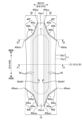
- FIG. 2 is a plan view of the diaper 1 with the absorbent main body 10 and the belt portion 30 stretched in the longitudinal direction;
- FIG. 3A is a schematic cross-sectional view of the diaper 1 in the state of FIG. 2 taken along line AA.
- FIG. 3B is a schematic cross-sectional view of the diaper 1 in the state of FIG. 2 taken along line BB.
- FIG. 5 is a diagram for explaining the relationship between forces acting on joints 40 when a conventional underpants-type diaper 5 is worn as a comparative example.
- FIG. 5 is a diagram for explaining the relationship between forces acting on joints 40 when a conventional underpants-type diaper 5 is worn as a comparative example.
- FIG. 10 is a perspective view showing the state of the leg openings LH of the diaper 1 when the diaper is put on.
- FIG. 10 is a diagram illustrating the arrangement of convex portions 40fp provided in the joint portion 40; 4 is an enlarged plan view for explaining the structure of a joint portion 40;
- FIG. 3 is a plan view showing a case where a joint portion 40 is provided with a discontinuous portion; 10A and 10B are diagrams showing a modification of the arrangement of the seal portion 41 forming the joint portion 40.
- FIG. FIG. 11 is a schematic plan view showing a modified example of the joint 40;
- FIG. 11 is a schematic plan view showing a modified example of the joint 40;
- FIG. 11 is a schematic plan view showing another modified example of the joint 40; It is the schematic front view which looked at the diaper 2 of 2nd Embodiment from the ventral side.
- 14A and 14B are diagrams illustrating an example of a method for forming the projecting portion 10t and the projecting portion 30t.
- FIG. 11 is a perspective view showing the state of the leg openings LH of the diaper 2 when the diaper is put on.
- the absorbent body has vertical, horizontal, and longitudinal directions that intersect with each other, and has an absorbent body, and a belt part that connects a front upper end portion and a rear upper end portion of the absorbent body, and a waist opening. and a pair of leg openings, wherein the belt portion is inclined from the upper side to the lower side in the vertical direction from the waist opening toward the leg openings and from the inner side to the outer side in the horizontal direction.
- a pants-type absorbent article joined to the absorbent main body wherein when the pants-type absorbent article in a stretched state is viewed along the front-rear direction, the joint portion is the joint portion
- the portion below the portion (convex portion) of the joint portion that protrudes inward in the left-right direction is worn. It floats from the wearer's skin side to the non-skin side, and the lower end of the joint does not come into contact with the wearer's skin. Therefore, it becomes difficult for the force to pull up the belt portion to act on the lower end of the joint portion, and it becomes difficult for the starting point of tearing to be formed at the lower end. As a result, the joint portion becomes difficult to break, and separation of the belt portion and the absorbent main body can be suppressed.
- the joint portion has a portion that protrudes inward in the lateral direction below an intermediate position between the upper end and the lower end of the joint portion in the vertical direction. It is desirable that there be
- the belt portion rises from the wearer's skin when the absorbent article is worn, compared to the case where the convex portion of the joint is provided above the intermediate position in the vertical direction.
- the area of the part becomes smaller. Therefore, deterioration of fit can be suppressed.
- the convex portion is arranged below the middle position in the vertical direction, the contractile force in the vicinity of the upper end portion of the belt portion is less likely to be hindered, and the belt portion can be prevented from slipping down.
- the joint portion is composed of a plurality of discretely arranged seal portions, and at least one of the plurality of seal portions is located from the central position in the vertical direction. It is desirable that the profile is curved on the lower side as well.
- the joining portion has a discontinuous portion between the upper end and the lower end in the vertical direction.
- the joint portion has a lower width in the vertical direction than the portion projecting inward in the left-right direction than the portion projecting inward in the left-right direction. It is desirable that the width of the upper side in the vertical direction is larger than the width of the upper side.
- the joint portion is composed of a plurality of discretely arranged seal portions, and is located on the lower side in the vertical direction than the portion projecting inward in the left-right direction.
- the density of the seal portions per unit area has a portion where the density of the seal portions per unit area on the upper side in the vertical direction is higher than the portion projecting inward in the left-right direction. , is desirable.
- the joint portion has a joined portion and a non-joined portion at the end on the non-skin side.
- At least a part of the upper end portion of the absorbent body has an absorbent body seal portion that joins only the sheet members constituting the absorbent body. is desirable.
- the absorbent main body sealing part is provided at the upper end of the absorbent main body, the sheet members (for example, the top sheet and the back sheet) constituting the absorbent main body ) can be prevented from fraying each other and the opening of the absorbent main body at the upper end portion.
- the joining material is larger in the high basis weight region than in the other regions, so the welding strength is reduced. It can be made easier to raise. Therefore, when the belt portion is pulled up during the wearing operation, the joint portion is less likely to break in the high basis weight region of the belt portion, and separation of the belt portion and the absorbent body can be easily suppressed.
- At least a portion of the lower end portion of the belt portion has a multi-layered region in which the number of laminated sheet members constituting the belt portion is larger than that of other portions. , is desirable.
- the joining material is larger in the multi-layered region than in the other regions, so that the welding strength is increased. can be made easier. Therefore, when the belt portion is pulled up during the wearing operation, the joint portion is less likely to break in the multi-layered region of the belt portion, and separation of the belt portion and the absorbent main body can be easily suppressed.
- the joint portion has a portion that protrudes inward in the left-right direction in the multi-layered region.
- the convex portion in the multi-layered region where the number of laminated layers is large and the rigidity is higher than other regions in the belt portion, the convex portion Even if a large force acts on the joint, the joint can be made difficult to break.
- the belt portion includes a stretchable sheet member that stretches in the left-right direction and a linear elastic member
- the joint portion includes the stretchable sheet member and the stretchable sheet member in the belt portion. It is desirable to have a portion projecting inward in the left-right direction below the portion where the linear elastic member is laminated.
- the portion of the belt portion where the stretchable sheet member and the linear elastic member are laminated becomes the most stressed when the belt portion is pulled up during the wearing operation. area. Therefore, by providing the convex portion below the relevant portion, it becomes difficult for an excessively large force to act on the convex portion, and the belt portion can be made more difficult to break.
- the pants-type absorbent article has a portion where the belt portion and the absorbent main body are continuous in a region below a lower end of the joint portion in the vertical direction. is desirable.
- a part of the base material (nonwoven fabric, etc.) constituting the belt portion and the absorbent main body is present between the lower end of the joint and the leg opening. Therefore, it becomes difficult for the force when the belt portion is pulled up during the wearing operation to act on the lower end of the joint portion. Therefore, formation of a starting point of tearing at the lower end of the joint can be suppressed, and the joint can be made more difficult to tear.
- the absorbent body has vertical, horizontal, and longitudinal directions that intersect with each other, and has an absorbent body and a belt part that connects a front upper end portion and a rear upper end portion of the absorbent body, and has a waist opening. and a pair of leg openings, wherein the belt portion is inclined from the waist opening toward the leg openings from the upper side to the lower side in the vertical direction and from the inner side to the outer side in the horizontal direction.
- the underpants-type absorbent article joined to the absorbent main body by a portion, wherein when the underpants-type absorbent article in a stretched state is viewed along the front-rear direction, the up-down direction of the joints At least one of the absorbent main body and the belt portion has a portion protruding toward the leg opening side at the lower end of the pants-type absorbent article. .
- the protruding portion formed on at least one of the absorbent main body and the belt portion is pulled from the wearer's skin side to the non-skin side. It floats to the side, and the lower end of the joint does not come into contact with the wearer's skin. Therefore, it becomes difficult for the force to pull up the belt portion to act on the lower end of the joint portion, and it becomes difficult for the starting point of tearing to be formed at the lower end. As a result, the joint portion becomes difficult to break, and separation of the belt portion and the absorbent main body can be suppressed.
- the absorbent body has vertical, horizontal, and longitudinal directions that intersect with each other, and has an absorbent body and a belt part that connects a front upper end portion and a rear upper end portion of the absorbent body, and has a waist opening. and a pair of leg openings, wherein the belt portion is inclined from the waist opening toward the leg openings from the upper side to the lower side in the vertical direction and from the inner side to the outer side in the horizontal direction.
- a pants-type absorbent article joined to the absorbent main body by a part, wherein when worn, the lower end part of the joint part rises from the wearer's skin side to the non-skin side, so that the lower end part
- the pants-type absorbent article is characterized in that the joints are arranged so as to create a gap with the wearer's skin.
- the portion below the portion (convex portion) of the joint portion that protrudes inward in the left-right direction is worn. It floats from the wearer's skin side to the non-skin side, and the lower end of the joint does not come into contact with the wearer's skin. Therefore, it becomes difficult for the force to pull up the belt portion to act on the lower end of the joint portion, and it becomes difficult for the starting point of tearing to be formed at the lower end. As a result, the joint portion becomes difficult to break, and separation of the belt portion and the absorbent main body can be suppressed.
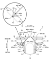
- FIG. 1 is a schematic front view of the diaper 1 viewed from the abdomen side, and a schematic cross-sectional view of the waist opening BH viewed from the upper side.
- FIG. 2 is a plan view of the diaper 1 with the absorbent body 10 and the belt portion 30 stretched in the longitudinal direction.
- FIG. 3A is a schematic cross-sectional view of the diaper 1 in the state of FIG. 2 taken along line AA.
- FIG. 3B is a schematic cross-sectional view of the diaper 1 in the state of FIG. 2 taken along line BB.
- the diaper 1 has "vertical direction”, “horizontal direction” and “front-rear direction” that are orthogonal to each other in the pants-type state shown in FIG.
- the upper side in the vertical direction is the wearer's “girth side” and the lower side in the vertical direction is the “crotch side” of the wearer.
- the front side in the front-rear direction is the wearer's “abdominal side”
- the rear side in the front-rear direction is the "back side” of the wearer.
- the diaper 1 is in a flat state elongated in the longitudinal direction as shown in FIG. 2 at the final stage of the manufacturing process.
- the flat diaper 1 has a "longitudinal direction” and a "width direction” that are perpendicular to each other.
- the "longitudinal direction” is a direction along the longitudinal direction of the absorbent main body 10, which corresponds to the up-down direction (FIG. 1) of the absorbent main body 10 in a pants-type state.
- the "width direction” is the direction corresponding to the left-right direction (FIG. 1) of the absorbent body 10 in the underpants-type state.
- FIG. 1 in FIG.
- the state of being "stretched in the longitudinal direction" means that the diaper 1 is stretched against the contractile force of an elastic member (for example, a waist elastic member 36 to be described later) arranged along the longitudinal direction. is elongated in the longitudinal direction to such an extent that wrinkles and gathers are substantially invisible in the portions where the elastic members are arranged. Therefore, the shape of the diaper 1 when it is stretched in the longitudinal direction is the same as the shape of the diaper 1 which extends flat when the elastic members do not exert any contractile force.
- an elastic member for example, a waist elastic member 36 to be described later
- the direction perpendicular to the longitudinal direction and the width direction is defined as the "thickness direction”
- the side in contact with the wearer's skin is defined as the “skin side”
- the opposite side is defined as the "non-skin side”.
- the diaper 1 includes an absorbent main body 10, a pair of belt portions 30, 30 joined to both lateral sides of the absorbent main body 10, a joint portion 40 joining the absorbent main body 10 and the belt portions 30, 30, It has
- the absorbent main body 10 has a substantially V-shaped tapered front end 10eLf and a rear end 10eLb in the longitudinal direction.
- the pair of belt portions 30, 30 mainly arranged around the waist of the wearer are arranged side by side in the width direction while being superimposed on the skin side surface of the absorbent main body 10.
- Each belt portion 30 is joined by joining portions 40 (40F, 40B) provided so as to be inclined along the V-shape of the end portions 10eLf, 10eLb of the absorbent main body 10.
- joining portions 40 40F, 40B
- each belt portion 30 is folded in half at substantially the center position CL30 in the longitudinal direction while the inner ends 30eW1 and 30eW1 in the width direction of the pair of belt portions 30 and 30 are opened to both sides in the width direction.
- the absorbent main body 10 is folded in half at the central position CL10 in the longitudinal direction. Then, the widthwise inner end portions 30eW1, 30eW1 of the belt portions 30, 30 and the longitudinal end portions 10eLf, 10eLb of the absorbent main body 10 form the waist opening BH of the diaper 1. As shown in FIG.
- a pair of leg openings LH, LH are formed by.
- the absorbent main body 10 is a sheet-like member whose longitudinal ends 10eLf and 10eLb are tapered in a substantially V shape in plan view, and covers the absorbent core 11 and the absorbent core 11 from the skin side.
- a top sheet 12, a back film 13 covering the absorbent core 11 from the non-skin side, a back sheet 14 laminated on the non-skin side of the back film 13, and both sides in the width direction (lateral direction) of the absorbent main body 10. has a side sheet 15 provided on the skin side of the back sheet 14, and leg elastic members 16 that extend and contract along the longitudinal direction (see FIG. 3). Each of these members is joined to a member adjacent in the thickness direction with a hot-melt adhesive or the like.
- the application pattern of the adhesive examples include an ⁇ pattern, a spiral pattern, a stripe pattern, and the like.
- the members may be joined using welding means such as thermal welding, ultrasonic welding, or other known joining means.
- the absorbent core 11 is a molded body obtained by molding a predetermined liquid absorbent material into a substantially oval shape as shown in FIG. 2 as an example of a predetermined shape.
- the liquid-absorbent material include liquid-absorbent fibers such as pulp fibers and liquid-absorbent granules such as superabsorbent polymers (so-called SAP).
- SAP superabsorbent polymers
- the shape of the absorbent core 11 is not limited to the elliptical shape as described above, and may be substantially an hourglass shape in plan view or other shape.
- the outer peripheral surface of the absorbent core 11 may be covered with a core wrap sheet (not shown) such as tissue paper.
- the top sheet 12 is, for example, a liquid-permeable sheet member such as an air-through nonwoven fabric, and is arranged so as to cover the absorbent core 11 from the skin side to the non-skin side as shown in FIG. 3A. Since the ends 10eLf and 10eLb of the absorbent main body 10 are formed at the ends 10eLf and 10eLb of the absorbent body 10, the longitudinal ends of the top sheet 12 are formed on the ventral side (front side) or the dorsal side (rear side) in the longitudinal direction. It has the above-mentioned substantially V-shaped tapered shape in which the dimension in the width direction becomes smaller as it progresses to the left.
- the back film 13 is a liquid-impermeable leak-proof sheet such as polyethylene (PE) film or polypropylene (PP) film.
- the backsheet 14 is a sheet member made of a soft, hydrophobic nonwoven fabric or the like, and is a member that constitutes the exterior of the absorbent body 10 .
- the back sheet 14 has a substantially V-shaped tapered shape in which the width dimension decreases toward the ventral side (front side) or the dorsal side (rear side) in the longitudinal direction.
- the side sheets 15 are made of a flexible, hydrophobic non-woven fabric or the like like the back sheet 14, and are joined to the skin side on both sides of the back sheet 14 in the width direction (lateral direction). Between the side sheet 15 and the back sheet 14 in the thickness direction, a plurality of leg elastic members 16 such as rubber threads are stretched in the longitudinal direction at a predetermined ratio, and are spaced apart in the width direction. installed. Based on the contractile force generated by the leg elastic members 16, stretchability along the longitudinal direction is applied to the outer ends 10e1, 10e1 in the width direction of the absorbent main body 10, that is, the leg openings LH, LH. is given, and the fit of the diaper 1 around the legs is improved.
- leg elastic members 16 such as rubber threads
- the member constituting the leg-hole elastic member 16 is not limited to the rubber thread or the like described above, and may be any member capable of exhibiting a contractile force along the longitudinal direction.
- it may be a stretchable sheet member such as a stretchable nonwoven fabric.
- the belt portion 30 connects a front end portion 10eLf (front upper end portion in the pants-shaped state in FIG. 1) and a rear end portion 10eLb (rear upper end portion in the pants-shaped state in FIG. 1) in the longitudinal direction of the absorbent main body 10. It is a belt-shaped member that connects, and has a non-skin side sheet 31, a skin side sheet 32, a waist elastic sheet 33, and a waist elastic member 36. - ⁇
- the non-skin-side sheet 31 and the skin-side sheet 32 are strip-shaped sheet members arranged along the longitudinal direction, and are made of, for example, spunbond nonwoven fabric or SMS nonwoven fabric. Both ends of the non-skin-side sheet 31 and the skin-side sheet 32 in the longitudinal direction are aligned with the shapes of the longitudinal ends 10eLf and 10eLb of the absorbent main body 10, and are placed on the belly side (front side) or the dorsal side (rear side) in the longitudinal direction. side), the dimension in the width direction becomes narrower.
- a portion of the non-skin-side sheet 31 has a folded portion 31f that is folded outward at an inner end portion 30eW1 in the width direction (lateral direction).
- a waist elastic sheet 33 and a plurality of waist elastic members 36 are provided between the non-skin side sheet 31 and the skin side sheet 32 in the thickness direction.
- the waist elastic sheet 33 is a stretchable sheet member having stretchability along the longitudinal direction, and is formed of stretchable nonwoven fabric or stretchable film, for example.
- the waist elastic sheet 33 is provided near the outer end 30e1 in the width direction of the belt portion 30 (near the bottom end of the belt portion 30 in the vertical direction in the pants-type state of FIG. 1).
- the sheet 33 imparts appropriate stretchability to the leg openings LH (outer ends 30e1).
- the waist elastic members 36 are linear elastic members such as thread rubber having elasticity along the longitudinal direction, and are arranged in plurality at intervals in the width direction.
- the waist elastic member 36 is provided near the inner end 30eW1 in the width direction of the belt portion 30 (near the upper end portion of the belt portion 30 in the vertical direction in the pants-type state of FIG. 1), and is provided at the waist opening BH of the diaper 1.
- the waist elastic members 36 are stacked in the thickness direction at the folded portion 31f near the inner end 30eW1, and the density is increased (see FIGS. 3A and 3B). Sufficient stretchability is imparted to the portion BH, making it easier to prevent the diaper 1 from slipping down when worn.
- a portion of the waist elastic member 36 overlaps the waist elastic sheet 33 .
- the joint portion 40 is a portion that joins the absorbent main body 10 and the belt portion 30, and has a pair of front joint portions 40F on the front side in the front-rear direction and a pair of rear joint portions 40B on the rear side.
- a pair of front joint portions 40F for joining the belt portions 30, 30 on both sides in the left-right direction. 40F is provided at the upper end portion 10eLf (the front end portion in the longitudinal direction of FIG. 2) on the front side of the absorbent main body 10.
- a pair of front joint portions 40F for joining the belt portions 30, 30 on both sides in the left-right direction. 40F is provided at the upper end portion 10eLf (the front end portion in the longitudinal direction of FIG. 2) on the front side of the absorbent main body 10.
- a pair of front joint portions 40F for joining the belt portions 30, 30 on both sides in the left-right direction. 40F is provided at the upper end portion 10eLf (the front end portion in the longitudinal direction of FIG. 2) on the front side of the absorbent main body 10.
- the joints 40 (the front joints 40F and the rear joints 40B) provided in the diaper 1 of this embodiment have a partially bent shape, as shown in FIGS. That is, the front joint portion 40F has a shape in which an upper portion 40fa and a lower portion 40fb in the vertical direction are bent at 40fp.
- the joining portion 40 has a portion (hereinafter also referred to as a convex portion 40fp) that protrudes inward in the left-right direction from the straight line connecting the upper end 40fea and the lower end 40feb.
- the rear joint portion 40B has a portion (convex portion 40bp) that protrudes inward in the horizontal direction from a straight line that connects the upper end 40bea and the lower end 40beb in the vertical direction.
- the joint portion 40 is formed by thermal welding or ultrasonic welding, and joins the absorbent main body 10 and the belt portion 30 .
- the bonding method by the bonding portion 40 is not limited to this example, and an adhesive, another bonding method, or a combination thereof may be used.
- the operation when wearing the diaper 1 will be described.
- the wearer's legs are passed through the pair of leg openings LH from the waist opening BH.
- the diaper 1 is pulled up from the wearer's toe side to the crotch portion by grasping both ends of the belt portion 30 in the left-right direction.
- the absorbent main body 10 is fitted to the crotch portion of the wearer, and the belt portion 30 is fitted to the waist portion of the wearer.
- FIG. 4 is a diagram for explaining the relationship between the forces acting on the joints 40 when the conventional pants-type diaper 5 is worn as a comparative example.
- the basic configuration of the pants-type diaper 5 (diaper 5) according to the comparative example is substantially the same as that of the diaper 1 according to the present embodiment, but the shape of the joint portion 40 is different.
- the joint portion 40 of the diaper 5 is formed in a straight line from the upper end 40fea to the lower end 40feb in the vertical direction, and does not have the convex portion 40fp like the diaper 1 between the upper end 40fea and the lower end 40feb. .
- a tensile force acts on the joint portion 40 (40F).
- a pulling force f1 acts on the lower end 40feb of the joint 40 in the same direction as F1.
- a downward drag g1 in the vertical direction acts on the lower end 40feb of the joint portion 40 .
- a force t1 directed upward in the vertical direction and inward in the horizontal direction acts on the lower end 40feb of the joint portion 40 so as to balance these forces f1 and g1.
- the force t1 acting on the lower end 40feb of the joint portion 40 increases and exceeds the joint strength of the joint portion 40.
- the joint portion 40 begins to tear starting from the lower end 40feb, the joint portion 40 begins to tear toward the upper end 40fea. Then, the tear propagates along the joint 40 .
- the belt portion 30 and the absorbent main body 10 may separate, or the diaper 5 may not be worn on the body.
- FIG. 5 is a diagram illustrating the relationship between forces acting on the joints 40 when the pants-type diaper 1 of the first embodiment is worn.
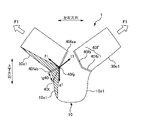
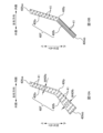
- FIG. 6 is a perspective view showing the state of the leg openings LH of the diaper 1 during the wearing operation.
- the waist opening BH formed by the belt portion 30 is widened outward in the left-right direction and pulled up in the up-down direction, similarly to the diaper 5 .
- the outer end portion of the belt portion 30 in the left-right direction is pulled by the obliquely upward force F1 (see FIG. 5).
- the diaper 1 is provided with the protrusion 40fp that protrudes inward in the left-right direction between the upper end 40fea and the lower end 40feb of the joint portion 40 .
- the circumference of the leg-hole opening LH of the diaper 1 becomes longer than when the convex portion 40fp is not provided.
- the joint portion 40 is formed on a straight line, that is, when the joint portion 40 is formed as a straight line extending from the upper end 40fea through the convex portion 40fp to the temporary lower end 40t, the temporary lower end 40t
- the position is at a distance lg40 from the lower end 40feb.
- the absorptive main body 10 in the leg openings LH is The peripheral length of the outer end (outer edge) 10e1 is increased by lg40.
- the outer end portion 10e1 of the absorbent main body 10 is a portion that abuts against the groin of the wearer when the diaper 1 is worn.
- a surplus of the fabric (non-woven fabric or the like) forming the end portion 10e1 tends to create a gap between it and the wearer's skin (groin). That is, the lower end 40feb of the joint portion 40 tends to rise from the wearer's skin side toward the non-skin side.
- the hatched region in FIG. 6 rolls up toward the non-skin side. It will be in a state where it does not come into contact with the wearer's skin.
- the point where the force F1 pulling up the belt portion 30 acts moves from the lower end 40feb of the joint portion 40 to the convex portion 40fp. Therefore, when the diaper 1 is put on, as shown in FIG. 5, the convex portion 40fp of the joint portion 40 is subjected to a pulling force f1 in the same direction as F1, a vertical downward drag force g1, and a vertical upward force f1. , and a force t1 acting inward in the left-right direction acts.
- the convex portion 40fp of the joint portion 40 is separated from the lower end 40feb by a predetermined distance.
- the cloth (nonwoven fabric, etc.) constituting the absorbent main body 10 and the belt portion 30 exists around the convex portion 40fp, even if the force (t1) is concentrated on the convex portion 40fp, the starting point of the tear is formed. hard to be That is, even if the belt portion 30 is pulled up when the diaper 1 is put on, the joint portion 40 is not easily broken, and the belt portion 30 and the absorbent main body 10 are separated, and the diaper 1 cannot be worn. It is suppressed.
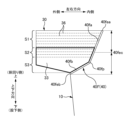
- FIG. 7A and 7B are diagrams for explaining the arrangement of the convex portions 40fp provided on the joint portion 40.
- FIG. 7 shows the planar shape of the belt portion 30 and the joint portion 40 when the pants-type diaper 1 is stretched vertically and horizontally.
- the convex portion 40fp is provided below an intermediate position 40fec between the upper end 40fea and the lower end 40feb of the joint portion 40 in the vertical direction.
- the area between the convex portion 40fp and the lower end 40feb when the diaper 1 is worn is from the wearer's skin side to the non-skin side. It becomes easier to float up. Therefore, if the convex portion 40fp is above the intermediate position 40fec in the vertical direction of the joint portion 40, the area where the belt portion 30 rises from the wearer's skin increases, and the fit around the wearer's legs increases.
- the convex portion 40fp is provided below the intermediate position 40fec of the joint portion 40 in the up-down direction. Therefore, the area where the belt portion 30 rises from the wearer's skin when the diaper 1 is worn is reduced. Therefore, it is possible to suppress deterioration of fit around the leg. Further, when the convex portion 40fp is arranged below the intermediate position 40fec, the contractile force of the waist elastic member 36 acting near the upper end portion of the belt portion 30 is less likely to be inhibited. is easily maintained, and slipping of the belt portion 30 can be suppressed.
- the number of sheet members stacked in the thickness direction at the lower end in the vertical direction is stacked in the thickness direction at other portions (upper end in the vertical direction, etc.). It is greater than the number of sheet members.
- the belt portion 30 has the non-skin-side sheet 31 and the skin-side sheet 32 laminated together, and furthermore, in a part of the region (lower end portion in the vertical direction), the belt portion 30 is formed between the non-skin-side sheet 31 and the skin-side sheet 32.
- a girth elastic sheet 33 is laminated on (see FIG. 3A etc.). In other words, at least a part of the lower end of the belt portion 30 becomes a multi-layered region (the region surrounded by the thick line in FIG.
- the protrusions 40fp of the joints 40 are provided in such multi-layered regions (see FIG. 7).
- the convex portion 40fp of the joint portion 40 is the portion that protrudes most inward in the left-right direction, and is the portion to which the greatest force acts when the belt portion 30 is pulled up. Therefore, by arranging the convex portion 40fp in the multi-laminated region of the belt portion 30, which has a large number of laminated layers and has a higher rigidity than other regions, when a large force acts on the convex portion 40fp. Even so, the joint portion 40 can be made more difficult to break.
- the basis weight of the sheet member forming the belt portion 30 at the lower end portion in the vertical direction is the same as that of the sheet member forming the belt portion 30 at other portions (upper end portion in the vertical direction, etc.). higher than the basis weight. That is, at least a portion of the lower end portion of the belt portion 30 is a high basis weight region having a higher basis weight than the upper end portion due to the presence of the waist elastic sheet 33 . In such a high basis weight region, when the belt portion 30 and the absorbent main body 10 are joined by the joining portion 40, the joining material is greater than in other regions, so that the welding strength can be easily increased. can.
- the joint portion 40 in the high basis weight region (lower end portion) of the belt portion 30 is less likely to break against the force pulling up the belt portion 30 obliquely upward. It becomes easy to suppress that the main body 10 separates. Further, as in the case described above, since the convex portion 40fp of the joint portion 40 is provided in such a high basis weight region, even when a large force acts on the convex portion 40fp, the joint portion 40 can be made more difficult to break.
- a region S1 is a region in which only a waist elastic member 36 (linear elastic member) such as thread rubber is arranged, and a waist elastic sheet 33 (stretchable) such as a stretchable nonwoven fabric is arranged. sheet member) is arranged, and the region where the waist elastic member 36 and the waist elastic sheet 33 are overlapped is S2. It is desirable to be provided on the lower side than (see FIG. 7). In the area S2, since the contractile force of the waist elastic member 36 and the waist elastic sheet 33 acts, this is the area where the stress is the strongest when the belt portion 30 is pulled up when the diaper 1 is put on.
- FIG. 8 is an enlarged plan view explaining the structure of the joint 40.
- the joints 40 are formed by discretely arranging a plurality of seals 41 formed by ultrasonic welding or thermal welding in predetermined regions. By arranging the plurality of fine seal portions 41 at intervals, the force acting on the joint portion 40 (for example, the force t1 in FIG. 5) is dispersed, making it difficult to concentrate on one point. 40 can be made difficult to tear.
- the shape of the seal portion 41 is curved on the lower side in the vertical direction. Specifically, as shown in FIG. 8, it is desirable that the contour of the seal portion 41 is curved below the central position of the seal portion 41 in the vertical direction.
- the seal portion 41 may be easily peeled off.
- a “corner” is formed by curving the contour of the lower side of the seal portion 41, the force (t1) acting on the seal portion 41 is difficult to concentrate at one point.
- the part 41 can be made difficult to peel off. Therefore, the joint 40 becomes more difficult to tear.
- FIG. 9 is a plan view showing a case where the joint 40 is provided with a discontinuous portion.
- a joint portion 40F (40) shown in FIG. 9 is formed in a substantially dotted line shape with a plurality of discontinuous portions formed between an upper end 40fea and a lower end 40feb.
- the joint portion 40F is formed by intermittently arranging a plurality of short band-shaped joint portions 40fn. For example, among the plurality of joints 40fn forming the joint 40F, one is a joint 40fn1, and the other adjacent to the joint 40fn1 with a space therebetween is a joint 40fn2.
- the discontinuous portion provided in the joint portion 40 may be the interval between the two adjacent seal portions 41, 41 in FIG. That is, the plurality of seal portions 41, 41... may be discretely arranged with a certain distance.
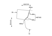
- FIG. 10A and 10B are diagrams showing a modification of the arrangement of the seal portion 41 forming the joint portion 40.
- FIG. 10A and 10B are diagrams showing a modification of the arrangement of the seal portion 41 forming the joint portion 40.
- the width of the joint 40 increases toward the bottom. That is, the width W40fb of the portion 40fb of the joint portion 40 below the protrusion 40fp is larger than the width W40fa of the portion 40fa above the protrusion 40fp (W40fb>W40fa).
- W40fb at the lower side (40fb) of the joint portion 40 has a larger portion than the width W40fa at the upper side (40fa)
- the force (t1) acting from the lower side to the upper side of the joint 40 in the vertical direction can be received by the wider portion of the lower side (40fb) of the joint 40 . Therefore, the force acting on the lower side (40fb) of the joint 40 can be easily dispersed in the width direction, and the breakage of the joint 40 can be easily suppressed.
- the density of the seal portion 41 forming the joint portion 40 increases toward the lower side of the joint portion 40 . That is, the area of the sealing portion 41 provided per unit area in the portion 40fb below the convex portion 40fp of the joint portion 40 is the same as the area of the sealing portion 41 provided per unit area in the portion 40fa above the convex portion 40fp. is larger than the area of In this way, the lower side (40fb) of the joint portion 40 has a portion where the density of the seal portion 41 is higher than the density of the seal portion 41 on the upper side (40fa). 40fb) is higher than that on the upper side (40fa).
- the joint portion 40 has a joined portion and a non-joined portion at the non-skin-side end (edge) in the thickness direction.
- the non-skin-side end (edge) of the joint 40 is the tip of the joints 40F and 40B protruding from the skin side to the non-skin side in the cross-sectional view of the waist opening BH in FIG. To tell.
- at least a portion of the plurality of seal portions 41 forming the joint portion 40 overlaps the non-skin side end of the joint portion 40 (the end 40e Albany indicated by the thick line in FIG. 8). It is That is, at least a part of the end 40 e .
- the seal portion 41 were formed on the entire end 40e on the non-skin side of the joint portion 40, the rigidity of the end 40e would be increased, and when the wearer touches the end 40e when the diaper 1 is worn, There is a possibility that it becomes easy to produce a sense of incongruity.
- the seal portion 41 is not formed on the entire end 40e on the non-skin side, friction between the diaper 1 and the wearer's clothes may cause the absorbent main body 10 and the belt portion 30 to be separated from each other at the end 40e. There is a risk that the bonding of the will be easy to peel off.
- a bonded portion and a non-bonded portion are provided at the non-skin-side end 40 e of the bonded portion 40 , so that the wearer can touch the bonded portion 40 . Even in the case where the joint portion 40 is attached, it is possible to prevent the joint portion 40 from being separated.
- a body seal portion 42 may be provided.
- FIG. 8 at least part of the upper end portion 10eLf on the front side of the absorbent main body 10, a plurality of adhesives for joining the top sheet 12 and the back sheet 14 (back film 13) constituting the absorbent main body 10 in the thickness direction. of absorbent body seal portion 42 is provided.
- the absorbent main body seal portion 42 is provided at the upper end portion 10eLf on the front side of the absorbent main body 10, the sheet members (the top sheet 12 and the back sheet 14) may be frayed, and the upper end portion 10eLf may be frayed. It is possible to suppress the occurrence of opening of the absorbent main body 10 .
- the seal portion 41 forming the joint portion 40 and the absorbent main body seal portion 42 provided at the upper end portion of the absorbent main body 10 can be formed simultaneously in the manufacturing process of the diaper 1 .
- the diaper 1 is stretched as shown in FIG.
- an absorbent main body seal portion 42 for welding the sheet members (12, 14) constituting the absorbent main body 10 in the thickness direction can be formed.
- FIG. 11 is a schematic plan view showing a modified example of the joint 40.
- the upper portion 40fa in the vertical direction and the lower portion 40fb in the vertical direction of the joint portion 40 are both linear, and the convex portion 40fp projects inward in the horizontal direction.
- the joint portion 40 may be partially curved as shown in FIG. 11 .
- the lower portion 40fb of the joint portion 40 in the vertical direction is formed in an arc shape that protrudes inward in the horizontal direction, and is smoothly connected to the upper portion 40fa in the vertical direction at the convex portion 40fp. .
- the force of pulling up the belt portion 30 during the wearing operation of the diaper 1 tends to act on the convex portion 40fp instead of the lower end 40feb.
- the upper portion 40fa and the lower portion 40fb of the joint portion 40 are continuously connected at the convex portion 40fp, and the lower portion 40fb is not formed with an angle, force is concentrated at this portion. it gets harder.
- the joint portion 40 (lower The length of the side portion 40fb) itself is increased. As a result, the force acting on the joint portion 40 is more likely to be dispersed, and breakage of the joint portion 40 can be easily suppressed.
- FIG. 12 is a schematic plan view showing another modification of the joint 40.
- the belt portion 30 and the absorbent body 10 have a continuous portion below the lower end 40 feb of the joint portion 40 . That is, the lower end 40feb of the joint portion 40 does not reach the leg opening LH, and the belt portion 30 and the base material ( Non-woven fabric, etc.) are present. Therefore, even if the belt portion 30 is pulled up when the diaper 1 is put on, formation of a starting point of tearing at the lower end 40feb is likely to be suppressed. Thereby, the joint 40 can be made more difficult to tear.
- FIG. 13 is a schematic front view of the diaper 2 of the second embodiment as seen from the ventral side.
- the diaper 2 of the second embodiment has a predetermined region including the lower end 40feb of the front joint portion 40F, and a part of the absorbent main body 10 and the belt portion 30 on the side of the leg opening LH. has a protruding part.
- the absorbent main body 10 has a protruding portion 10t that protrudes toward the leg opening LH side
- the belt portion 30 has a protruding portion 30t that protrudes toward the leg opening LH side. (both of which are hatched in the partial enlarged view of FIG. 13).
- the absorbent main body 10 and the belt portion 30 have a portion protruding toward the leg opening LH (not shown in FIG. 13).
- the projecting portion 10t and the projecting portion 30t can be identified as follows. First, a line passing through the lower end 40feb of the front joint portion 40F and perpendicular to the front joint portion 40F (assumed to be an auxiliary line PL) is drawn. Next, the outer edge 10e1 of the absorbent main body 10 (outline of the leg opening LH formed by the absorbent main body 10) and the outer edge 30e1 of the belt portion 30 (outline of the leg opening LH formed by the belt portion 30). and a common tangent line (common tangent line TL) is drawn.
- a portion where the absorbent main body 10 exists and a portion where the absorbent main body 10 does not exist are formed in the region between the auxiliary line PL and the common tangent line TL.
- a portion where the absorbent main body 10 exists between the auxiliary line PL and the common tangent line TL becomes the projecting portion 10t.
- a portion where the belt portion 30 exists and a portion where it does not exist are formed in the region between the auxiliary line PL and the common tangent line TL. 30 tons.
- the intersection of the common tangent line TL and the front joint portion 40F is defined as an intermediate point 40fq. That is, the intermediate point 40fq is located between the upper end 40fea and the lower end 40feb of the front joint portion 40F.
- the joint portion 40 is formed in a straight line, but the joint portion 40 is bent or curved between the upper end 40fea and the lower end 40feb as in the diaper 1 of the first embodiment. It may be a configuration that Regarding the diaper 2, the basic configuration other than the above (for example, the configuration of the absorbent main body 10 and the belt portion 30, the configuration of the seal portion 41 forming the joint portion 40, etc.) is the diaper described in the first embodiment. 1, detailed description is omitted.
- FIGS. 14A and 14B are diagrams illustrating an example of a method for forming the projecting portion 10t and the projecting portion 30t.
- the projecting portion 10t and the projecting portion 30t are formed by notching (cutting) part of the absorbent main body 10 and the belt portion 30 in a region closer to the front joint portion 40F than the auxiliary line PL in the manufacturing process of the diaper 2.
- FIG. 14A shows a portion of the diaper 2 before the projections 10t and 30t are formed at the lower end 40feb of the front joint 40F.
- the sheet member constituting the absorbent main body 10 and the belt portion 30 is present on the entire side of the front joint portion 40F with respect to the auxiliary line PL passing through the lower end 40feb. In other words, there is no portion where the absorbent main body 10 and the belt portion 30 do not exist on the front joint portion 40F side of the auxiliary line PL.
- only one of the projecting portion 10t and the projecting portion 30t may be formed.
- only one of the protrusion 10t and the protrusion 30t is formed by cutting out only one of the absorbent main body 10 and the protrusion 30t on the front joint portion 40F side of the auxiliary line PL. It may be
- FIG. 15 is a perspective view showing the state of the leg openings LH of the diaper 2 during the wearing operation.
- the leg openings The circumference of LH is longer. Therefore, the material is left over at the protruding portions 10t and 30t of the leg openings LH, and a gap is likely to occur between the wearer's skin (groin) and the wearer's skin (groin). That is, the protruding portion 10t and the protruding portion 30t are easily lifted from the wearer's skin side to the non-skin side. As a result, starting from the intermediate point 40fq, the shaded areas (protrusions 10t, 30t) in FIG. The lower end 40feb does not come into contact with the wearer's skin.
- the point at which the force pulling up the belt portion 30 acts moves from the lower end 40feb of the joint portion 40 to the intermediate point 40fq. That is, the intermediate point 40fq functions in the same manner as the convex portion 40fp in the diaper 1 of the first embodiment, and the force tends to concentrate on the intermediate point 40fq. Since the projecting portion 10t and the projecting portion 30t are interposed between the intermediate point 40fq and the lower end 40feb of the joint portion 40, even if a force acts on the intermediate point 40fq, the lower end 40feb It is difficult for force to act, and it is difficult to form the starting point of the tear.
- the pants-type diaper 1 was described as an example of the pants-type absorbent article, but the present invention can also be applied to pants-type absorbent articles other than pants-type diapers.
- it may be a pants-type napkin (shorts-type napkin) or a pants-type (shorts-type) absorbent pad for children or adults.
Abstract
Description
本発明の他の特徴については、本明細書及び添付図面の記載により明らかにする。
<おむつ1の基本構成>
第1実施形態に係るパンツ型吸収性物品の一例として、パンツ型使い捨ておむつ1(以下、「おむつ1」とも呼ぶ)の基本的な構成について説明する。図1は、おむつ1を腹側から見た概略正面図、及び胴回り開口部BHを上側から見た概略断面図である。図2は、吸収性本体10及びベルト部30を長手方向に伸長させた状態のおむつ1の平面図である。図3Aは、図2の状態のおむつ1のA-A線における概略断面図である。図3Bは、図2の状態のおむつ1のB-B線における概略断面図である。
吸収性本体10は、長手方向における各端部10eLf,10eLbがそれぞれ平面視略V字形に先細った形状のシート状部材であり、吸収性コア11と、同吸収性コア11を肌側から覆うトップシート12と、同吸収性コア11を非肌側から覆うバックフィルム13と、バックフィルム13よりも非肌側に積層されたバックシート14と、吸収性本体10の幅方向(左右方向)両側においてバックシート14の肌側に設けられたサイドシート15と、長手方向に沿って伸縮する脚回り弾性部材16とを有する(図3参照)。これらの各部材は、それぞれ、厚さ方向に隣接する部材と、ホットメルト接着剤等で接合されている。なお、同接着剤の塗布パターンとしては、Ωパターンやスパイラルパターン、ストライプパターン等を例示できる。また、接着剤を用いた接合手段の他に、例えば熱溶着,超音波溶着等の溶着手段や、その他公知の接合手段を用いて各部材が接合されるのであっても良い。
ベルト部30は、吸収性本体10の長手方向における前側端部10eLf(図1のパンツ型状態における前側上端部)と後側端部10eLb(図1のパンツ型状態における後側上端部)とを連結する帯状の部材であり、非肌側シート31と、肌側シート32と、胴回り弾性シート33と、胴回り弾性部材36とを有する。
接合部40は、吸収性本体10とベルト部30とを接合する部位であり、前後方向における前側に一対の前側接合部40Fと後側に一対の後側接合部40Bを有している。具体的に、吸収性本体10の前側における上端部10eLf(図2の長手方向における前側端部)には、左右方向の両側にベルト部30,30を接合するための一対の前側接合部40F,40Fが設けられている。同様に、後側における上端部10eLb(図2の長手方向における後側端部)には、左右方向の両側にベルト部30,30を接合するための一対の後側接合部40B,40Bが設けられている。前側接合部40F及び後側接合部40Bは、それぞれ、胴回り開口部BHから脚回り開口部LHに向かって上下方向の上側から下側、且つ、左右方向の内側から外側へ傾斜するように構成されている。
次に、おむつ1を着用する際の動作について説明する。通常、おむつ1のようなパンツ型使い捨ておむつを着用する際には、以下のような動作が行われる。先ず、胴回り開口部BHから一対の脚回り開口部LHに着用者の脚をそれぞれ通す。次いで、ベルト部30の左右方向の両端部を掴んで着用者のつま先側から股間部へとおむつ1を引っ張り上げる。そして、吸収性本体10を着用者の股間部へフィットさせると共に、ベルト部30を着用者の胴回り部へフィットさせる。
第2実施形態では、吸収性本体10とベルト部30とを接合する接合部40(40F,40B)の下端部周辺の構造が異なるパンツ型使い捨ておむつ2(以下、「おむつ2」とも呼ぶ)について説明する。図13は、第2実施形態のおむつ2を腹側から見た概略正面図である。
以上、本発明の実施形態について説明したが、上記の実施形態は、本発明の理解を容易にするためのものであり、本発明を限定して解釈するためのものではない。また、本発明は、その趣旨を逸脱することなく、変更や改良され得るとともに、本発明にはその等価物が含まれるのは言うまでもない。例えば、以下に示すような変形が可能である。
2 おむつ(パンツ型吸収性物品、第2実施形態)、
5 おむつ(パンツ型吸収性物品、比較例)、
10 吸収性本体、
10eLf 端部、10eLb 端部、10e1 外側端部、
10t 突出部、
11 吸収性コア、
12 トップシート、13 バックフィルム、14 バックシート、15 サイドシート、16 脚回り弾性部材、
30 ベルト部、
30eW1 内側端部、30e1 外側端部、
30t 突出部、
31 非肌側シート、31f 折り返し部、32 肌側シート、
33 胴回り弾性シート、36 胴回り弾性部材、
40 接合部、
40F 前側接合部、
40fa 部位(上側)、40fea 上端、
40fb 部位(下側)、40feb 下端、
40fp 凸部、40fq 中間点、
40fec 中間位置、
40B 後側接合部、
40ba 部位(上側)、40bea 上端、
40bb 部位(下側)、40beb 下端、
40bp 凸部、
41 シール部、42 吸収性本体シール部、
BH 胴回り開口部、LH 脚回り開口部、
CL10 中央位置(吸収性本体)、CL30 中央位置(ベルト部)
Claims (16)
- 互いに交差する上下方向と左右方向と前後方向とを有し、
吸収性本体と、前記吸収性本体の前側上端部と後側上端部とを連結するベルト部と、を有し、
胴回り開口部と一対の脚回り開口部とを備え、
前記ベルト部が、前記胴回り開口部から前記脚回り開口部に向かって前記上下方向の上側から下側且つ前記左右方向の内側から外側へ傾斜した接合部によって、前記吸収性本体と接合されている、パンツ型吸収性物品であって、
伸長状態の前記パンツ型吸収性物品を前記前後方向に沿って見たときに、
前記接合部は、前記接合部の前記上下方向における上端と下端とを結んだ直線よりも、前記左右方向の内側に凸となる部分を有している、ことを特徴とするパンツ型吸収性物品。 - 請求項1に記載のパンツ型吸収性物品であって、
前記接合部は、前記上下方向において前記接合部の上端と下端との中間位置よりも下側に、前記左右方向の内側に凸となる部分を有している、ことを特徴とするパンツ型吸収性物品。 - 請求項1または2に記載のパンツ型吸収性物品であって、
前記接合部のうち前記左右方向の内側に凸となる部分の少なくとも一部が湾曲している、ことを特徴とするパンツ型吸収性物品。 - 請求項1~3の何れか1項に記載のパンツ型吸収性物品であって、
前記接合部は、離散して配置された複数のシール部によって構成されており、
複数の前記シール部のうち少なくとも何れかは、前記上下方向における中央位置よりも下側において、輪郭が湾曲している、ことを特徴とするパンツ型吸収性物品。 - 請求項1~4の何れか1項に記載のパンツ型吸収性物品であって、
前記接合部は、前記上下方向における上端と下端との間に、非連続部を有している、ことを特徴とするパンツ型吸収性物品。 - 請求項1~5の何れか1項に記載のパンツ型吸収性物品であって、
前記接合部は、前記左右方向の内側に凸となる部分よりも前記上下方向における下側における幅の方が、前記左右方向の内側に凸となる部分よりも前記上下方向における上側における幅よりも大きくなる部分を有している、ことを特徴とするパンツ型吸収性物品。 - 請求項1~6の何れか1項に記載のパンツ型吸収性物品であって、
前記接合部は、離散して配置された複数のシール部によって構成されており、
前記左右方向の内側に凸となる部分よりも前記上下方向における下側における単位面積当たりの前記シール部の密度の方が、前記左右方向の内側に凸となる部分よりも前記上下方向における上側における単位面積当たりの前記シール部の密度よりも大きくなる部分を有している、ことを特徴とするパンツ型吸収性物品。 - 請求項1~7の何れか1項に記載のパンツ型吸収性物品であって、
前記接合部は、非肌側の端において、接合されている部分と接合されていない部分とを有している、ことを特徴とするパンツ型吸収性物品。 - 請求項1~8の何れか1項に記載のパンツ型吸収性物品であって、
前記吸収性本体の上端部の少なくとも一部において、前記吸収性本体を構成しているシート部材のみを接合する吸収性本体シール部を有している、ことを特徴とするパンツ型吸収性物品。 - 請求項1~9の何れか1項に記載のパンツ型吸収性物品であって、
前記ベルト部の下端部の少なくとも一部において、他の部分よりも坪量が高い高坪量領域を有している、ことを特徴とするパンツ型吸収性物品。 - 請求項1~9の何れか1項に記載のパンツ型吸収性物品であって、
前記ベルト部の下端部の少なくとも一部において、他の部分よりも前記ベルト部を構成しているシート部材の積層枚数が多い多積層領域を有している、ことを特徴とするパンツ型吸収性物品。 - 請求項11に記載のパンツ型吸収性物品であって、
前記接合部は、前記多積層領域において、前記左右方向の内側に凸となる部分を有している、ことを特徴とするパンツ型吸収性物品。 - 請求項1~12の何れか1項に記載のパンツ型吸収性物品であって、
前記ベルト部は、前記左右方向に伸縮する伸縮性シート部材及び線状弾性部材を有し、
前記接合部は、前記ベルト部のうち前記伸縮性シート部材と前記線状弾性部材とが積層されている部分より前記上下方向の下側に、前記左右方向の内側に凸となる部分を有している、ことを特徴とするパンツ型吸収性物品。 - 請求項1~13の何れか1項に記載のパンツ型吸収性物品であって、
前記上下方向において、前記接合部の下端よりも下側の領域に、前記ベルト部と前記吸収性本体とが連続している部分を有している、ことを特徴とするパンツ型吸収性物品。 - 互いに交差する上下方向と左右方向と前後方向とを有し、
吸収性本体と、前記吸収性本体の前側上端部と後側上端部とを連結するベルト部と、を有し、
胴回り開口部と一対の脚回り開口部とを備え、
前記ベルト部が、前記胴回り開口部から前記脚回り開口部に向かって前記上下方向の上側から下側且つ前記左右方向の内側から外側へ傾斜した接合部によって、前記吸収性本体と接合されている、パンツ型吸収性物品であって、
伸長状態の前記パンツ型吸収性物品を前記前後方向に沿って見たときに、
前記接合部の前記上下方向における下端部において、前記吸収性本体及び前記ベルト部の少なくとも一方が、前記脚回り開口部側に向かって突出した部分を有している、ことを特徴とするパンツ型吸収性物品。 - 互いに交差する上下方向と左右方向と前後方向とを有し、
吸収性本体と、前記吸収性本体の前側上端部と後側上端部とを連結するベルト部と、を有し、
胴回り開口部と一対の脚回り開口部とを備え、
前記ベルト部が、前記胴回り開口部から前記脚回り開口部に向かって前記上下方向の上側から下側且つ前記左右方向の内側から外側へ傾斜した接合部によって、前記吸収性本体と接合されている、パンツ型吸収性物品であって、
着用時において、前記接合部の下端部が着用者の肌側から非肌側に浮き上がることによって前記下端部と前記着用者の肌との間に隙間が生じるように、前記接合部が配置されている、ことを特徴とする、パンツ型吸収性物品。
Priority Applications (2)
| Application Number | Priority Date | Filing Date | Title |
|---|---|---|---|
| EP21951956.8A EP4353210A1 (en) | 2021-07-30 | 2021-12-13 | Pants-type absorbent article |
| JP2023538211A JPWO2023007763A1 (ja) | 2021-07-30 | 2021-12-13 |
Applications Claiming Priority (2)
| Application Number | Priority Date | Filing Date | Title |
|---|---|---|---|
| CN202110871047.5A CN115670799A (zh) | 2021-07-30 | 2021-07-30 | 短裤型吸收性物品 |
| CN202110871047.5 | 2021-07-30 |
Publications (1)
| Publication Number | Publication Date |
|---|---|
| WO2023007763A1 true WO2023007763A1 (ja) | 2023-02-02 |
Family
ID=85058745
Family Applications (1)
| Application Number | Title | Priority Date | Filing Date |
|---|---|---|---|
| PCT/JP2021/045859 WO2023007763A1 (ja) | 2021-07-30 | 2021-12-13 | パンツ型吸収性物品 |
Country Status (4)
| Country | Link |
|---|---|
| EP (1) | EP4353210A1 (ja) |
| JP (1) | JPWO2023007763A1 (ja) |
| CN (1) | CN115670799A (ja) |
| WO (1) | WO2023007763A1 (ja) |
Citations (5)
| Publication number | Priority date | Publication date | Assignee | Title |
|---|---|---|---|---|
| JPH10179639A (ja) | 1997-11-05 | 1998-07-07 | Procter & Gamble Far East Inc | ウエスト開口部全体を伸縮自在とした使い捨ておむつ |
| JP2016193057A (ja) * | 2015-03-31 | 2016-11-17 | ユニ・チャーム株式会社 | 使い捨て着用物品 |
| JP2016220947A (ja) * | 2015-05-29 | 2016-12-28 | ユニ・チャーム株式会社 | 吸収性物品 |
| JP2017012273A (ja) * | 2015-06-29 | 2017-01-19 | ユニ・チャーム株式会社 | 吸収性物品 |
| JP2017012281A (ja) * | 2015-06-29 | 2017-01-19 | ユニ・チャーム株式会社 | 吸収性物品 |
-
2021
- 2021-07-30 CN CN202110871047.5A patent/CN115670799A/zh active Pending
- 2021-12-13 WO PCT/JP2021/045859 patent/WO2023007763A1/ja active Application Filing
- 2021-12-13 EP EP21951956.8A patent/EP4353210A1/en active Pending
- 2021-12-13 JP JP2023538211A patent/JPWO2023007763A1/ja active Pending
Patent Citations (5)
| Publication number | Priority date | Publication date | Assignee | Title |
|---|---|---|---|---|
| JPH10179639A (ja) | 1997-11-05 | 1998-07-07 | Procter & Gamble Far East Inc | ウエスト開口部全体を伸縮自在とした使い捨ておむつ |
| JP2016193057A (ja) * | 2015-03-31 | 2016-11-17 | ユニ・チャーム株式会社 | 使い捨て着用物品 |
| JP2016220947A (ja) * | 2015-05-29 | 2016-12-28 | ユニ・チャーム株式会社 | 吸収性物品 |
| JP2017012273A (ja) * | 2015-06-29 | 2017-01-19 | ユニ・チャーム株式会社 | 吸収性物品 |
| JP2017012281A (ja) * | 2015-06-29 | 2017-01-19 | ユニ・チャーム株式会社 | 吸収性物品 |
Also Published As
| Publication number | Publication date |
|---|---|
| EP4353210A1 (en) | 2024-04-17 |
| CN115670799A (zh) | 2023-02-03 |
| JPWO2023007763A1 (ja) | 2023-02-02 |
Similar Documents
| Publication | Publication Date | Title |
|---|---|---|
| EP2522323B1 (en) | Disposable wearing article | |
| KR101509833B1 (ko) | 일회용 기저귀 및 흡수성 물품 | |
| JP6230351B2 (ja) | 使い捨て着用物品 | |
| EA032244B1 (ru) | Впитывающее изделие | |
| JP3206405U (ja) | 使い捨て着用物品 | |
| JP6429710B2 (ja) | 使い捨ての着用物品 | |
| JP4190074B2 (ja) | ウイング付き生理用ナプキン | |
| WO2023007763A1 (ja) | パンツ型吸収性物品 | |
| CN107735062B (zh) | 内裤型的吸收性物品 | |
| JP2003038573A (ja) | パンツ型使い捨ておむつ | |
| JP6422811B2 (ja) | 使い捨て着用物品 | |
| JP6559940B2 (ja) | パンツ型吸収性物品 | |
| CN111971010B (zh) | 内裤型的穿着物品 | |
| JP2569768Y2 (ja) | 使い捨てパンツ型着用物品 | |
| JP2003093445A (ja) | パンツ型使い捨ておむつ | |
| JP2004181253A (ja) | 使い捨ての尿とりパッド | |
| JP6419012B2 (ja) | 使い捨て着用物品 | |
| JP6422810B2 (ja) | 使い捨ての着用物品 | |
| CN115551452B (zh) | 吸收性物品 | |
| WO2023007764A1 (ja) | パンツ型吸収性物品 | |
| JP7321974B2 (ja) | パンツ型吸収性物品 | |
| WO2023127567A1 (ja) | テープ型おむつ | |
| JP2607820Y2 (ja) | 使い捨てパンツ型着用物品 | |
| JPH087850Y2 (ja) | 使い捨てパンツ型着用物品 | |
| JPWO2018123047A1 (ja) | 吸収性物品 |
Legal Events
| Date | Code | Title | Description |
|---|---|---|---|
| 121 | Ep: the epo has been informed by wipo that ep was designated in this application |
Ref document number: 21951956 Country of ref document: EP Kind code of ref document: A1 |
|
| WWE | Wipo information: entry into national phase |
Ref document number: 2401000120 Country of ref document: TH |
|
| WWE | Wipo information: entry into national phase |
Ref document number: 2021951956 Country of ref document: EP |
|
| WWE | Wipo information: entry into national phase |
Ref document number: 2023538211 Country of ref document: JP |
|
| ENP | Entry into the national phase |
Ref document number: 2021951956 Country of ref document: EP Effective date: 20240111 |
|
| NENP | Non-entry into the national phase |
Ref country code: DE |