WO2023007760A1 - 自転車用スタンド - Google Patents
自転車用スタンド Download PDFInfo
- Publication number
- WO2023007760A1 WO2023007760A1 PCT/JP2021/044803 JP2021044803W WO2023007760A1 WO 2023007760 A1 WO2023007760 A1 WO 2023007760A1 JP 2021044803 W JP2021044803 W JP 2021044803W WO 2023007760 A1 WO2023007760 A1 WO 2023007760A1
- Authority
- WO
- WIPO (PCT)
- Prior art keywords
- bicycle
- support member
- bicycle stand
- stand according
- side wall
- Prior art date
Links
- 230000003014 reinforcing effect Effects 0.000 claims description 34
- 210000000078 claw Anatomy 0.000 claims description 5
- 238000005452 bending Methods 0.000 claims description 3
- 238000010586 diagram Methods 0.000 description 34
- 239000000463 material Substances 0.000 description 10
- 238000012856 packing Methods 0.000 description 6
- 230000000694 effects Effects 0.000 description 5
- 238000012986 modification Methods 0.000 description 4
- 230000004048 modification Effects 0.000 description 4
- XEEYBQQBJWHFJM-UHFFFAOYSA-N Iron Chemical compound [Fe] XEEYBQQBJWHFJM-UHFFFAOYSA-N 0.000 description 2
- 239000000919 ceramic Substances 0.000 description 1
- 238000006073 displacement reaction Methods 0.000 description 1
- 229910052742 iron Inorganic materials 0.000 description 1
- 230000013011 mating Effects 0.000 description 1
- 239000002184 metal Substances 0.000 description 1
- 229910052751 metal Inorganic materials 0.000 description 1
- 230000001151 other effect Effects 0.000 description 1
- 238000004806 packaging method and process Methods 0.000 description 1
- 239000000123 paper Substances 0.000 description 1
- 239000002994 raw material Substances 0.000 description 1
- 230000002787 reinforcement Effects 0.000 description 1
- 239000011347 resin Substances 0.000 description 1
- 229920005989 resin Polymers 0.000 description 1
- 239000002023 wood Substances 0.000 description 1
Images


Classifications
-
- B—PERFORMING OPERATIONS; TRANSPORTING
- B62—LAND VEHICLES FOR TRAVELLING OTHERWISE THAN ON RAILS
- B62H—CYCLE STANDS; SUPPORTS OR HOLDERS FOR PARKING OR STORING CYCLES; APPLIANCES PREVENTING OR INDICATING UNAUTHORIZED USE OR THEFT OF CYCLES; LOCKS INTEGRAL WITH CYCLES; DEVICES FOR LEARNING TO RIDE CYCLES
- B62H1/00—Supports or stands forming part of or attached to cycles
- B62H1/02—Articulated stands, e.g. in the shape of hinged arms
- B62H1/04—Substantially U-shaped stands for embracing the rear wheel
Definitions
- the present invention relates to a bicycle stand used when practicing riding a bicycle.
- Patent Document 1 describes a portable bicycle stand that supports a bicycle wheel on which a bicycle wheel is placed, in which a pair of left and right support members that sandwich and support the wheel from both left and right sides of the wheel, and the support member a leg member connected to the lower end of the support member; and a hinge member connected to a vertical intermediate portion of the support member.
- the hinge members include a pair of hinge pieces on the front side that connect the middle points of the left and right pillar members on the front side of the support member so as to be separated from each other, and the middle points of the left and right pillar members on the rear side of the support member. a pair of hinge pieces on the rear side that are connected to each other so as to be separated from each other, and one end of the hinge piece in each pair of the hinge pieces on the front side and the rear side is pivotally supported in the middle of the column member, and the other ends are connected to each other.
- a bicycle stand characterized in that the hinge member and the support member are closed so that the beam members come closer to each other, and the wheel is sandwiched and supported from the left and right sides.
- Patent Literature 1 it is possible to provide a portable bicycle stand that can hold a wheel tire with good workability and suppress lateral movement of the wheel by simply placing the wheel on the stand, and that can stably support the bicycle. ing.
- the present invention has been made in view of the above problems, and provides a bicycle stand that enables the practice of pedaling independently of the balancing operation when practicing riding a bicycle. for the purpose.
- the present invention provides a support member having at least a pair of side walls, a pivot supporting the end of a shaft of a bicycle wheel, and a support member engaging an upper edge of the side wall. and a pair of pivot members having a portion. Also, a part of the package in which the bicycle was packed can be used as the support member. Furthermore, a nut member having an outer diameter larger than the inner diameter of the shaft support portion and screwed onto the end of the shaft can be provided.
- the shaft support member may have hook-shaped bicycle engaging portions that engage with both left and right sides of the part of the bicycle, and the pair of side wall portions are separated from each other by a distance of the upper edge.
- the interval may be narrower than the interval between the lower ends.
- the bicycle engaging portion may be formed with a rib for preventing misalignment between the side wall portion and the shaft support member, and may be formed with a groove to be inserted into the upper edge, and the groove may be formed on the shaft support portion. It may extend in the longitudinal direction of the member and be inclined in the width direction of the pivot member.
- a fixing member that engages with the support member to fix the relative positions of the pair of side wall portions may be further provided, and the fixing member may be connected to the pair of shaft support members.
- the support member may be a cardboard member.
- the support member may have a notch on the upper edge of the side wall for fitting into the pivot, and a reinforcing member fitted and assembled to the bottom of the support member to prevent distortion of the support member.
- a member may be provided, the reinforcing member may be a cardboard member similar to the support member.
- the reinforcing member has a rectangular shape before use, and is assembled by raising both ends in the extension direction into a prismatic shape extending in the direction of the side ends and raising the both ends.
- the reinforcing member is assembled by inserting a trapezoidal pawl member provided by cutting into the bottom surface portion into a square hole provided in the prismatic member.
- the reinforcing member has a second rectangular hole in the prismatic member, the supporting member has a second trapezoidal claw provided by cutting, and the second trapezoidal claw Preferably, a portion engages the second square hole to form an engaging portion.
- the support member includes a base member formed by bending the right side wall portion and the left side wall portion in parallel with each other through the bottom portion, and a front side member and a rear side member orthogonal to the right side wall portion and the left side wall portion. It may be a combination of
- FIG. 1 is a schematic diagram showing a configuration example of a bicycle stand according to a first embodiment of the present invention
- FIG. 1 is a vertical sectional view showing a structural example of a bicycle stand according to a first embodiment of the present invention
- FIG. 4 is a schematic diagram showing a modified example of the bicycle stand according to the first embodiment of the present invention
- FIG. 4 is a vertical cross-sectional view showing a modified example of the bicycle stand according to the first embodiment of the present invention
- FIG. 4 is a schematic diagram showing a configuration example of a bicycle stand according to a second embodiment of the invention
- FIG. 4 is a vertical cross-sectional view showing a configuration example of a bicycle stand according to a second embodiment of the present invention
- FIG. 4 is a vertical cross-sectional view showing a configuration example of a bicycle stand according to a second embodiment of the present invention
- FIG. 7 is a schematic diagram showing a configuration example of a pivot member according to a second embodiment of the present invention
- FIG. 11 is a schematic diagram showing a configuration example of a bicycle stand according to a third embodiment of the present invention
- FIG. 11 is a schematic diagram showing a configuration example of a bicycle stand according to a fourth embodiment of the present invention
- FIG. 11 is a schematic diagram showing a configuration example of a shaft support member according to a fifth embodiment of the present invention
- FIG. 11 is a schematic diagram showing a configuration example of a shaft support member according to a fifth embodiment of the present invention
- FIG. 11 is a schematic diagram showing a configuration example of a shaft support member according to a fifth embodiment of the present invention
- FIG. 11 is a schematic diagram showing a configuration example of a shaft support member according to a fifth embodiment of the present invention
- FIG. 11 is a schematic diagram showing a configuration example of a shaft support member according to a fifth embodiment of the present invention
- FIG. 11 is a schematic diagram showing
- FIG. 11 is a schematic diagram showing a configuration example of a shaft support member according to a fifth embodiment of the present invention
- FIG. 11 is a schematic diagram showing an example of attaching a pivot member according to a fifth embodiment of the present invention
- FIG. 11 is a schematic diagram showing a configuration example of a bicycle stand according to a sixth embodiment of the present invention
- FIG. 11 is a schematic diagram showing a configuration example of a bicycle stand according to a sixth embodiment of the present invention
- FIG. 11 is a schematic diagram showing a configuration example of a bicycle stand according to a sixth embodiment of the present invention
- FIG. 11 is a schematic plan view showing a configuration example of a bicycle stand according to a sixth embodiment of the present invention
- FIG. 11 is a schematic plan view showing a configuration example of a bicycle stand according to a sixth embodiment of the present invention
- FIG. 11 is a schematic diagram showing a configuration example of a bicycle stand according to a seventh embodiment of the present invention
- FIG. 11 is a schematic diagram showing a configuration example of a reinforcing member according to a seventh embodiment of the present invention
- FIG. 11 is a schematic diagram showing a configuration example of a reinforcing member according to a seventh embodiment of the present invention
- FIG. 11 is a schematic diagram showing a configuration example of a bicycle stand according to a seventh embodiment of the present invention
- FIG. 21 is a partially enlarged view showing a structural example of a bicycle stand according to a seventh embodiment of the present invention
- FIG. 21 is an exploded view showing a configuration example of a bicycle stand according to an eighth embodiment of the present invention
- FIG. 21 is a perspective view showing a configuration example of a bicycle stand according to an eighth embodiment of the present invention
- FIG. 20 is a plan view showing a configuration example of a bicycle stand according to an eighth embodiment of the present invention
- FIG. 21 is an exploded perspective view showing a configuration example of a bicycle stand according to a ninth embodiment of the present invention
- FIG. 8 is a perspective view showing a state assembled from the state of FIG. 7
- FIG. 21 is a perspective view showing a configuration example of a bicycle stand according to a ninth embodiment of the present invention
- FIG. 20 is a side view showing an example of use of the bicycle stand according to the ninth embodiment of the present invention.
- FIG. 1 is a schematic diagram showing a configuration example of a bicycle stand 100 according to this embodiment.
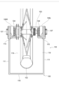
- FIG. 2 is a vertical cross-sectional view through the center of the tire showing a structural example of the bicycle stand 100. As shown in FIG.
- a bicycle 101 includes, as an example, a rear wheel 102, a rear wheel axle 103 positioned at the center of the rear wheel 102, and extending to the left and right sides of the rear wheel 102. and a frame 104 that supports the wheel shaft 103 from the left and right.
- Bicycle 101 also includes a saddle, pedals, a chain cover, and a chain.
- the bicycle stand 100 includes a support member 105, a pair of shaft support members 106R and 106L, a nut member 107 screwed to each of the left and right ends of the rear wheel axle 103, It has
- the support member 105 is formed in the shape of a rectangular parallelepiped whose longitudinal direction is the front-rear direction of the bicycle 101, and has an open upper surface.
- the support member 105 has at least a pair of side wall portions 111 facing left and right side surfaces of the bicycle 101, an upper edge portion 112 of the side wall portions 111, a front portion 116, a rear portion 117, and a bottom portion 118.
- a notch 113 is formed at a portion of 116 corresponding to the rear wheel 102 .
- the shaft support member 106R and the shaft support member 106L are respectively a shaft support portion 114 that supports the end portion of the rear wheel shaft 103 of the rear wheel 102 that is the wheel of the bicycle 101, and a support member that engages with the upper edge portion 112 of the side wall portion 111. and an engaging portion 119 .
- the pivot member 106R and the pivot member 106L further have hook-shaped bicycle engaging portions 115 that engage both left and right sides of the frame 104 that is part of the bicycle 101. As shown in FIG. 2, the pivot member 106R and the pivot member 106L further have hook-shaped bicycle engaging portions 115 that engage both left and right sides of the frame 104 that is part of the bicycle 101. As shown in FIG. 2, the pivot member 106R and the pivot member 106L further have hook-shaped bicycle engaging portions 115 that engage both left and right sides of the frame 104 that is part of the bicycle 101. As shown in FIG.
- the nut member 107 has an outer diameter larger than the inner diameter of the shaft support portion 114 of the shaft support members 106R and 106L, and is screwed to the left and right ends of the rear wheel shaft 103 respectively.
- the nut member 107 and the bicycle engaging portion 115 prevent the shaft support member 106R and the shaft support member 106L from coming off the end of the rear wheel axle 103 even when the support member 105 is distorted. can be done.
- the support member 105 of the bicycle stand 100 is a cardboard member, and is formed of a part of the cardboard that is the package in which the bicycle 101 is packed. Therefore, the lateral width of the support member 105 is greater than the width of the bicycle 101 . Also, the front part 116 is formed by bending the side or bottom of the corrugated cardboard. The strength of the support member 105, which is a cardboard member, can be ensured by placing the bicycle 101 on the cardboard in the longitudinal grain state. In addition, the distance between the pair of side wall portions 111 of the support member 105 is the same between the upper edges 112 and between the lower ends.
- the bicycle stand 100 when practicing riding the bicycle 101, it is possible to practice pedaling independently of the balancing operation. Therefore, children or the like who are unfamiliar with the movement of pedaling can practice the movement of pedaling independently of balancing, so that they can pedal smoothly when actually riding the bicycle 101. can run.
- the bicycle stand 100 by using the cardboard boxes in which the bicycle 101 was packed, the number of newly prepared parts other than the parts of the bicycle 101 is minimized, thereby reducing the burden on the environment and reducing the cost. can be reduced.
- FIG. 3 is a schematic diagram showing a configuration example of a bicycle stand 120 that is a modification of the bicycle stand 100.
- FIG. 4 is a vertical sectional view showing a structural example of a bicycle stand 120 according to this modified example.
- the bicycle stand 120 includes a support member 121, a pair of shaft support members 122R and 122L, and left and right end portions of the rear wheel shaft 103, which are screwed together. and a mating nut member 123 .
- the support member 121 is formed in a substantially rectangular parallelepiped shape whose longitudinal direction is the front-rear direction of the bicycle 101, and has an open upper surface.
- the support member 121 includes at least a pair of side wall portions 131 facing the left and right side surfaces of the bicycle 101 , an upper edge portion 132 of the side wall portions 131 , and a notch portion 133 formed on the front side surface of the rear wheel 102 . ,have.
- the shaft support member 122R and the shaft support member 122L are respectively a shaft support portion 134 that supports the end portion of the rear wheel shaft 103 of the rear wheel 102 that is the wheel of the bicycle 101, and a support member that engages with the upper edge portion 132 of the side wall portion 131. and an engaging portion.
- the pair of side wall portions 131 have inclined surfaces that are inclined in a direction in which the axial support member 122R and the axial support member 122L engaged with the upper edge portions 132 of each other approach. As a result, the distance between the pair of side wall portions 131 is narrower between the upper edges 132 than between the lower ends. At the position where the axial support member 122R and the axial support member 122L are engaged, planes parallel to each other are formed without being inclined.
- the pivot member 122R and the pivot member 122L further have hook-shaped bicycle engaging portions 135 that engage both left and right sides of the frame 104 that is part of the bicycle 101. As shown in FIG. 4, the pivot member 122R and the pivot member 122L further have hook-shaped bicycle engaging portions 135 that engage both left and right sides of the frame 104 that is part of the bicycle 101. As shown in FIG. 4, the pivot member 122R and the pivot member 122L further have hook-shaped bicycle engaging portions 135 that engage both left and right sides of the frame 104 that is part of the bicycle 101. As shown in FIG.
- the nut member 123 has an outer diameter larger than the inner diameter of the shaft support portion 134 of the shaft support member 122R and the shaft support member 122L, and is screwed to the left and right ends of the rear wheel shaft 103 respectively.
- the nut member 123 and the bicycle engaging portion 135 prevent the shaft support member 122R and the shaft support member 122L from coming off the end of the rear wheel axle 103 even when the support member 121 is distorted. can be done.
- the pedaling practice is performed independently of the balancing operation. becomes possible. Moreover, it is possible to reduce the cost while reducing the burden on the environment.
- the distance between the pair of side wall portions 131 is narrower between the upper edges 132 than between the lower ends. It can suppress left and right shaking during driving practice and improve stability.
- the bicycle stand 120 can reduce the thickness of the shaft support members 122R and 122L in the width direction of the bicycle compared to the bicycle stand 100, thereby reducing materials.
- FIG. 5 is a schematic diagram showing a configuration example of the bicycle stand 200 according to this embodiment.
- FIG. 6 is a vertical cross-sectional view through the center of the tire showing a structural example of the bicycle stand 200.
- FIG. 7 is a schematic diagram showing a configuration example of the pivot member according to the present embodiment.
- a bicycle 151 includes, as an example, a rear wheel 102, a rear wheel axle 103 positioned at the center of the rear wheel 102, and extending to the left and right side surfaces of the rear wheel 102. and a frame 104 that supports the wheel shaft 103 from the left and right.
- the bicycle 151 also includes a saddle 152, pedals 153, a chain cover 154, and a chain.
- the bicycle stand 200 includes a support member 201, a pair of shaft support members 202R and 202L, and nut members 203 screwed to the left and right ends of the rear axle 103, respectively. ing.
- the support member 201 is formed in the shape of a rectangular parallelepiped whose longitudinal direction is the front-rear direction of the bicycle 151, and has an open upper surface.
- the support member 201 includes at least a pair of side wall portions 211 facing left and right side surfaces of the bicycle 151 , an upper edge portion 212 of the side wall portions 211 , and a notch portion 213 formed in the front side surface of the rear wheel 102 . ,have.
- the shaft support member 202R and the shaft support member 202L are respectively a shaft support portion 214 that supports the end portion of the rear wheel shaft 103 of the rear wheel 102, which is the wheel of the bicycle 151, and a support member that engages with the upper edge portion 212 of the side wall portion 211. and an engaging portion. Also, the pivot members 202R and 202L extend in the forward direction of the bicycle 151 along the upper edge 212 and extend to the surface where the notch 213 is formed.
- the nut member 203 has an outer diameter larger than the inner diameter of the shaft support portion 214 of the shaft support member 202R and the shaft support member 202L, and is screwed to the left and right ends of the rear wheel shaft 103 respectively.
- the pair of side wall portions 211 have inclined surfaces that are inclined in the direction in which the axial support member 202R and the axial support member 202L engaged with the upper edge portions 212 approach each other. As a result, the distance between the pair of side wall portions 211 is narrower between the upper edges 212 than between the lower ends.
- the shaft support member 202L has a groove 221 that is inserted into the upper edge portion 212 in the support member engaging portion that engages the upper edge portion 212.
- the groove 221 extends in the longitudinal direction of the shaft support member 202L and is inclined in the width direction of the shaft support member 202L. Vertical ribs are provided inside the grooves 221 to prevent displacement in the horizontal direction and to reduce raw materials and ensure strength.
- a groove similar to the groove 221 is also formed in the shaft support member 202R.
- pedaling can be practiced independently of the balancing operation. can be done. Moreover, it is possible to reduce the cost while reducing the burden on the environment.
- the axial support member 202R and the axial support member 202L extend forward of the bicycle 151 along the upper edge portion 212 and extend to the side surface where the notch portion 213 is formed, distortion of the support member 201 can be reduced. Therefore, it becomes possible to perform pedal practice more stably.
- FIG. 8 is a schematic diagram showing a configuration example of the bicycle stand 300 according to this embodiment.
- a bicycle 151 includes, as an example, a rear wheel 102, a rear wheel axle 103 positioned at the center of the rear wheel 102, a frame 104 protecting the left and right sides of the rear wheel 102, It has The bicycle 151 also includes a saddle 152, pedals 153, a chain cover 154, and a chain.
- the bicycle stand 300 includes a support member 301, a pair of shaft support members 302R and 302L, and nut members 303 screwed to the left and right ends of the rear axle 103, respectively. ing.
- the support member 301 is formed in a rectangular parallelepiped shape whose longitudinal direction is the front-rear direction of the bicycle 151, and has an open upper surface.
- the support member 301 includes at least a pair of side wall portions 311 facing the left and right side surfaces of the bicycle 151, an upper edge portion 312 of the side wall portions 311, a cutout portion formed on the front side surface of the rear wheel 102, have.
- the shaft support member 302R and the shaft support member 302L are respectively a shaft support portion 314 that supports the end portion of the rear wheel shaft 103 of the rear wheel 102 that is the wheel of the bicycle 151, and a support member that engages with the upper edge portion 312 of the side wall portion 311. and an engaging portion.
- the bicycle stand 300 further includes a fixing member 315 that engages with a notch formed on the front surface of the support member 301 to fix the relative position of the pair of side walls 311 .
- the nut member 303 has an outer diameter larger than the inner diameter of the shaft support portion 314 of the shaft support members 302R and 302L, and is screwed to the left and right ends of the rear wheel shaft 103 respectively.
- the pair of side wall portions 311 have inclined surfaces that are inclined in a direction in which the axial support member 302R and the axial support member 302L engaged with the upper edge portions 312 of each other approach. As a result, the distance between the pair of side wall portions 311 is narrower between the upper edges 312 than between the lower ends.
- pedaling can be practiced independently of the balancing operation. can be done. Moreover, it is possible to reduce the cost while reducing the burden on the environment.
- the distance between the pair of side wall portions 311 is formed such that the distance between the upper edges 312 is narrower than the distance between the lower ends, and the fixing member 315 is provided.
- the fixing member 315 can prevent the support member 301 from being distorted.
- alignment triangles printed facing each other on the support member 301, the shaft support member 302R, the shaft support member 302L, and the fixing member 315 are provided to prevent mounting in the wrong position and to ensure accurate mounting. It is
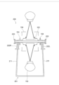
- FIG. 9 is a schematic diagram showing a configuration example of the bicycle stand 400 according to this embodiment.
- a bicycle 151 includes, as an example, a rear wheel 102, a rear wheel axle 103 positioned at the center of the rear wheel 102, a frame 104 protecting the left and right sides of the rear wheel 102, It has The bicycle 151 also includes a saddle 152 , pedals 153 and a chain cover 154 .
- the bicycle stand 400 includes a support member 401, a pair of shaft support members 402R and 402L, and nut members 403 screwed to the left and right ends of the rear axle 103, respectively. ing.
- the support member 401 is formed in the shape of a rectangular parallelepiped whose longitudinal direction is the front-rear direction of the bicycle 151, and has an open upper surface.
- the support member 401 includes at least a pair of side wall portions 411 facing left and right side surfaces of the bicycle 151, an upper edge portion 412 of the side wall portion 411, a cutout portion formed in the front side surface of the rear wheel 102, have.
- the shaft support member 402R and the shaft support member 402L are respectively a shaft support portion 414 that supports the end portion of the rear wheel shaft 103 of the rear wheel 102 that is the wheel of the bicycle 151, and a support member that engages with the upper edge portion 412 of the side wall portion 411. and an engaging portion. Also, the pivot members 402R and 402L extend forward of the bicycle 151 along the upper edge 412 and extend to the side surface where the notch 413 is formed.
- the bicycle stand 400 further integrally includes a fixing member 415 that engages with a notch formed on the front side of the support member 401 and fixes the relative position of the pair of side walls 411 .
- the fixing member 415 is coupled with a pair of pivot members 402R and 402L.
- the nut member 403 has an outer diameter larger than the inner diameter of the shaft support portion 414 of the shaft support member 402R and the shaft support member 402L, and is screwed to the left and right ends of the rear wheel shaft 103 respectively.
- the pair of side wall portions 411 have inclined surfaces that are inclined in a direction in which the axial support member 402R and the axial support member 402L engaged with the upper edge portions 412 of each other approach. As a result, the distance between the pair of side wall portions 411 is narrower between the upper edges 412 than between the lower ends.
- pedaling can be practiced independently of the balancing operation. can be done. Moreover, it is possible to reduce the cost while reducing the burden on the environment.
- the distance between the pair of side wall portions 411 is narrower between the upper edges 412 than between the lower ends, and the fixing member 415 is provided.
- the fixing member 415 is integrally formed with the pair of shaft support members 402R and 402L, distortion of the support member 401 can be further suppressed.
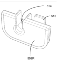
- FIG. 10 is a schematic diagram showing a configuration example viewed from the surface of the pivot member 502R.
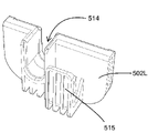
- FIG. 11 is a schematic diagram showing a configuration example viewed from the rear surface of the pivot member 502R.
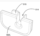
- FIG. 12 is a schematic diagram showing a configuration example viewed from the surface of the axial support member 502L.
- FIG. 13 is a schematic diagram showing a configuration example viewed from the rear surface of the pivot member 502L.
- FIG. 14 is a schematic diagram showing an example of attachment of the pivot member 502L.
- the shaft support member 502R includes, for example, a shaft support portion 514 that supports the end of the rear wheel shaft 103 of the rear wheel 102, which is the wheel of the bicycle 101 similar to that of the first embodiment, and a side wall. and a support member engaging portion that engages the upper edge portion 112 of the portion 111 .
- the pivot member 502R has hook-shaped bicycle engaging portions 515 that engage with both left and right sides of the frame 104 that is a part of the bicycle 101 .
- a plurality of ribs may be formed on the bicycle engaging portion 515 of the pivot member 502R to prevent misalignment between the side wall portion 111 and the pivot member 502R, increase strength, and save materials.
- the shaft support member 502L has a shaft support portion 514 and a support member engaging portion, similar to the shaft support member 502R.
- the pivot member 502L has a hook-shaped bicycle engaging portion 515. As shown in FIG.
- a bicycle engaging portion 515 of the pivot member 502L is formed with a plurality of ribs 516 for preventing misalignment between the side wall portion 111 and the pivot member 502L, increasing strength and saving materials.
- the support member 502R is attached to the upper edge 112 of the side wall 111 by engaging the support member engaging portion, and supports the end of the rear axle 103 with the support 514.
- the bicycle engaging portion 515 is engaged with the frame 104 . Due to the shape of the pivot member 502R, the rear end 521 of the frame 104 can also be engaged with the bicycle engaging portion 515 and fixed. Note that the shaft support member 502L can also be fixed by engaging the frame 104 in the same manner as the shaft support member 502R.
- the bicycle stand using the axial support member 502R and the axial support member 502L according to the present embodiment similar to the bicycle stand 100 according to the first embodiment, when practicing riding the bicycle 101, it is possible to maintain balance. It becomes possible to practice pedaling independently of the operation to take. At this time, by using the bicycle engaging portion to engage with a frame such as a chain stay or a seat stay, the end of the rear wheel axle does not come off from the pivot member even without the nut member.
- FIG. 15 and 16 are schematic diagrams showing examples of components of the bicycle stand 600.
- FIG. FIG. 17 is a schematic diagram showing a configuration example of the bicycle stand 600.
- FIG. 18 is a schematic plan view showing a configuration example of the bicycle stand 600. As shown in FIG.
- the bicycle stand 600 includes, for example, a support member 601 and a reinforcement member 602 that prevents the support member 601 from being distorted.
- the support member 601 is formed in a rectangular parallelepiped shape whose longitudinal direction is the front-rear direction of the bicycle 101, and the upper surface and the front side surface are open.
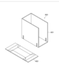
- the reinforcing member 602 is a cardboard member like the support member 601, and has a rectangular shape before use as shown in FIG. When using the reinforcing member 602 , as shown in FIG. 16 , both ends in the extending direction are protruded in a mountain shape, and both side ends are erected to assemble the reinforcing member 602 .
- the assembled reinforcing member 602 is fitted into the bottom of the support member 601 to secure the support member 601 .
- the support member 601 is prevented from being distorted. It is possible to increase the strength of and increase the stability during driving practice.
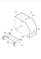
- FIG. 19 is a schematic diagram showing an example of components of the bicycle stand 700.
- FIG. 20 and 21 are schematic diagrams showing configuration examples of the reinforcing member according to the present embodiment.
- FIG. 22 is a schematic diagram showing a configuration example of the bicycle stand 700.
- FIG. 23 is a partially enlarged view showing a configuration example of the bicycle stand 700. As shown in FIG.
- the bicycle stand 700 includes, for example, a support member 701 and a reinforcing member 702 that prevents the support member 701 from being distorted.
- the support member 701 is formed in a rectangular parallelepiped shape whose longitudinal direction is the front-rear direction of the bicycle 101, and the upper surface and the front side surface are open.
- the upper edge of the side wall is provided with a notch 701a for fitting to the pivot of the support member.
- the support member 701 has a pair of side wall portions whose front upper corners are cut off to form inclined portions. As a result, it is possible to prevent the rear portion of the foot from coming into contact with the support member 701 during pedal practice.
- the reinforcing member 702 is a cardboard member like the support member 701, and has a rectangular shape before use as shown in FIG.
- both ends in the extension direction are raised in a prismatic shape extending in the direction of the side ends, the both side ends are raised, and the bottom is provided by a cut.
- the trapezoidal pawl member 702a is inserted into a rectangular hole 702b provided in the prism portion to assemble the reinforcing member 702. As shown in FIG.
- the assembled reinforcing member 702 is fitted into the bottom of the support member 701 to secure the support member 701 .
- a trapezoidal claw portion 701b provided by cutting the support member 701 engages with a rectangular hole 702c provided in the reinforcing member 702 to form an engaging portion, thereby firmly fixing the reinforcing member 702. .
- the support member 701 is prevented from being distorted. It is possible to increase the strength of and increase the stability during driving practice.
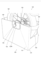
- FIG. 24 is an exploded view showing a configuration example of a bicycle stand according to an eighth embodiment of the present invention
- FIG. 25 is a perspective view thereof
- FIG. 26 is a plan view thereof.
- the bicycle stand 800 has the above-described pair of pivot members 502R and 502L attached to the upper edge of the support member 810, which supports the axle of the rear wheel of the bicycle.
- the support member 810 is made of a separately prepared cardboard box instead of the cardboard packing material of the bicycle. Even in this case, the individual parts described below are small enough that they can be included in the cardboard packaging of the bicycle and do not have to be shipped separately. Of course, it may be configured by cutting out a part of the cardboard of the packing material of the bicycle.
- the supporting member 810 is assembled in a parallel cross-beam shape, and is arranged such that a front side member 805 and a rear side member 806 parallel to each other are orthogonal to a base member 804 including a right side wall portion 801 and a left side wall portion 802 parallel to each other and a bottom portion 803 . is combined with A pair of pivot members 502R and 502L are attached to the upper edges of the right side wall portion 801 and the left side wall portion 802, respectively.
- the base member 804 is formed by folding a single plate-shaped member into a U-shaped cross section in a valley fold, and a right side wall portion 801, a left side wall portion 802, and a bottom portion 803 are formed. Furthermore, a pair of slits 841 and 842 extending from the right side wall portion 801 through the bottom portion 803 to the left side wall portion 802 are provided, and the front side member 805 and the rear side member 806 are engaged with the slits 841 and 842 .
- the front side member 805 and the rear side member 806 have the same shape, and are constructed by folding a single plate-like member into mountain folds along the center line 870 to form a front side portion 871 and a rear side portion 872 which are line symmetrical. be. Furthermore, a pair of slits 873 and 874 are provided symmetrically about the center line 870 , and these slits 873 and 874 are engaged with the above-described slits 841 and 842 and are also engaged with the right side wall portion 801 and the left side wall portion 802 . In addition, a notch 875 for avoiding the tire of the bicycle is provided in the center in the left-right direction, thereby preventing the tire of the bicycle from being hit when the bicycle is set on the bicycle stand 800 and pedal practice is performed.
- the bi-fold front member 805 and rear member 806 allow the bicycle to move in the lateral direction. It is possible to increase the strength against shaking and increase the stability during driving practice. Also, if the bicycle packing material cannot be used, an effective and compact bicycle stand can be provided at a low cost and can be included in the bicycle packing material.
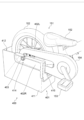
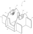
- FIG. 27 is an exploded view showing a configuration example of a bicycle stand according to the ninth embodiment of the present invention
- FIG. 28 is a perspective view showing its assembled state
- FIG. 29 is a perspective view showing its bottom surface
- FIG. It is a side view which shows a use condition.
- Bicycle stand 900 has a pair of shaft support members 902R and 902L, which have the same function as the above-described shaft support members, attached to the upper edge of support member 901. These support the axle of the rear wheel of the bicycle. support.
- the support member 901 is formed by cutting out a part including the lower corners of the cardboard box of the packing material of the bicycle.
- the support member 901 is cut out so that the top and front are open, and cutouts 901a and 901b are provided in the upper edges of the left and right side walls for attaching a pair of the shaft support member 902R and the shaft support member 902L.
- the support member 901 has upper and lower slits 901c and 901e in front of the left side wall portion with which the reinforcing member 903 engages, and similarly has upper and lower slits 901d in front of the right side wall portion with which the reinforcing member 903 engages. , 901f.
- the reinforcing portion 903 is bent into a V shape via a folding line extending to the left and right, and has a pair of vertical slits 903a and 903b passing through the folding line.
- the slits 903a and 903b engage with the upper and lower slits 901c, 901e, 901d and 901f, thereby engaging the reinforcing member 903 with the support member 901 and reducing the distortion of the support member 901 caused by the bicycle swinging in the horizontal direction. do.
- a bottom flap 901g which is a corrugated cardboard forming part of the bottom surface of the support member 901, is cut along the broken line to form a notch 901h. Since the bottom flap 901g has a flap shape, it can be easily inserted into the inside of the box member. ing. Even if the bottom flap 901g is raised when the bicycle stand 900 is used with the bicycle placed thereon as shown in FIG. It never hits the bottom flap 901g.
- the reinforcing member 903 increases the strength against shaking of the bicycle in the left-right direction, making it easier to practice riding. can increase the stability of In addition, by using bicycle packing materials, it is possible to provide an effective and compact bicycle stand at a low cost, which contributes to saving resources.
- the material of the pivot member and the support member may be paper, wood, resin, metal such as iron, or ceramic.
Landscapes
- Engineering & Computer Science (AREA)
- Mechanical Engineering (AREA)
- Packaging Of Machine Parts And Wound Products (AREA)
Abstract
Description
まず、図1および図2を参照して、本発明の第1実施形態に係る自転車用スタンドの構成例について説明する。図1は、本実施形態に係る自転車用スタンド100の構成例を示す模式図である。図2は、自転車用スタンド100の構成例を示すタイヤの中心を通る垂直断面図である。
次に、図3および図4を参照して、本実施形態に係る自転車用スタンド100の変形例について説明する。図3は、自転車用スタンド100の変形例である自転車用スタンド120の構成例を示す模式図である。図4は、本変形例に係る自転車用スタンド120の構成例を示す垂直断面図である。
次に、図5から図7を参照して、第2実施形態に係る自転車用スタンド200の構成例について説明する。図5は、本実施形態に係る自転車用スタンド200の構成例を示す模式図である。図6は、自転車用スタンド200の構成例を示すタイヤの中心を通る垂直断面図である。図7は、本実施形態に係る軸支部材の構成例を示す模式図である。
次に、図8を参照して、第3実施形態に係る自転車用スタンド300の構成例について説明する。図8は、本実施形態に係る自転車用スタンド300の構成例を示す模式図である。
次に、図9を参照して、第4実施形態に係る自転車用スタンド400の構成例について説明する。図9は、本実施形態に係る自転車用スタンド400の構成例を示す模式図である。
次に、図10から図14を参照して、第5実施形態に係る自転車用スタンドに用いる一対の軸支部材502Rおよび軸支部材502Lの構成例について説明する。図10は、軸支部材502Rの表面から見た構成例を示す模式図である。図11は、軸支部材502Rの裏面から見た構成例を示す模式図である。図12は、軸支部材502Lの表面から見た構成例を示す模式図である。図13は、軸支部材502Lの裏面から見た構成例を示す模式図である。図14は、軸支部材502Lの取り付け例を示す模式図である。
次に、図15から図18を参照して、第6実施形態に係る自転車用スタンド600の構成例について説明する。図15および図16は、自転車用スタンド600の構成物品例を示す模式図である。図17は、自転車用スタンド600の構成例を示す模式図である。図18は、自転車用スタンド600の構成例を示す平面模式図である。
次に、図19から図23を参照して、第7実施形態に係る自転車用スタンド700の構成例について説明する。図19は、自転車用スタンド700の構成物品例を示す模式図である。図20および図21は、本実施形態に係る補強部材の構成例を示す模式図である。図22は、自転車用スタンド700の構成例を示す模式図である。図23は、自転車用スタンド700の構成例を示す部分拡大図である。
次に、図24から図26を参照して、第8実施形態に係る自転車用スタンド800の構成例について説明する。図24は本発明の第8実施形態に係る自転車用スタンドの構成例を示す展開図であり、図25はその斜視図、図26はその平面図である。
次に、図27から図30を参照して、第9実施形態に係る自転車用スタンド900の構成例について説明する。図27は本発明の第9実施形態に係る自転車用スタンドの構成例を示す展開図であり、図28はその組み立てた状態を示す斜視図、図29はその底面を示す斜視図、図30は使用状態を示す側面図である。
101、151 自転車
102 後輪
103 後輪軸
104 フレーム
105、121、201、301、401、601、701、810、901 支持部材(ダンボール部材)
106R、106L、122R、122L、202R、202L、302R、302L、402R、402L、502R、502L 軸支部材
107、123、203、303、403 ナット部材
111、131、211、311、411 側壁部
112、132、212、312、412 上縁部
113、133、213 切欠き部
114、134、214、314、414、514 軸支部
115、135、515 自転車係合部
152 サドル
153 ペダル
154 チェーンカバー
221 溝
315、415 固定部材
316 リブ
521 フレーム先端部
602、702、903 補強部材
Claims (18)
- 少なくとも一対の側壁部を有する支持部材と、
自転車の車輪の軸の端部を支える軸支部と前記側壁部の上縁に係合する支持部材係合部とを有する一対の軸支部材と、
を備えた、自転車用スタンド。 - 前記支持部材は、前記自転車が梱包されていた包装体の一部である、請求項1に記載の自転車用スタンド。
- 前記軸支部の内径より大きな外径を有し、前記軸の端部に螺合されるナット部材をさらに備えた、請求項1または2に記載の自転車用スタンド。
- 前記軸支部材は、前記自転車の一部の左右両側に係合する鉤形状の自転車係合部を有する、請求項1から3のいずれか一項に記載の自転車用スタンド。
- 前記一対の側壁部の互いの距離は、前記上縁の間が下端の間よりも狭く、前記一対の軸支部材は、前記支持部材係合部が幅方向に傾斜している、請求項1から4のいずれか一項に記載の自転車用スタンド。
- 前記自転車係合部には、垂直方向のリブが形成されている、請求項5に記載の自転車用スタンド。
- 前記支持部材係合部には、前記上縁に差し込まれる溝が形成され、
前記溝は、前記軸支部材の長手方向に延在する、請求項1から6のいずれか一項に記載の自転車用スタンド。 - 前記支持部材に係合し、前記一対の側壁部の相対的な位置を固定する固定部材をさらに備えた、請求項1から7のいずれか一項に記載の自転車用スタンド。
- 前記固定部材が、前記一対の軸支部材と連結されている、請求項8に記載の自転車用スタンド。
- 前記支持部材が、ダンボール部材である、請求項1から9のいずれか一項に記載の自転車用スタンド。
- 前記支持部材は、前記側壁部の上縁に、前記軸支部に嵌合するための切り欠きを備えた、請求項1から10のいずれか一項に記載の自転車用スタンド。
- 前記支持部材の歪みを防ぐために支持部材の底部にはめ込んで組み立てられる補強部材を備える、請求項1から11のいずれか一項に記載の自転車用スタンド。
- 前記補強部材は、ダンボールであって、使用前は矩形を成し、使用する際には、延在方向の両端を側端部方向に伸びる角柱形状に隆起させ、両側端部を立てて起こして組み立てられる、請求項12に記載の自転車用スタンド。
- 前記補強部材は、底面部に切り込みにより設けられた台形状の爪部材を前記角柱形状の部材に設けられた方形穴に差し込んで組み立てられる、請求項13に記載の自転車用スタンド。
- 前記補強部材は、前記角柱形状の部材に第二の方形穴を有し、前記支持部材は、切り込みにより設けられた第二の台形状の爪部を有し、前記第二の台形状の爪部が前記第二の方形穴に係合して係合部を形成する、請求項13または14のいずれか一項に記載の自転車用スタンド。
- 前記支持部材は、前記右側壁部及び前記左側壁部が底部底部を介して互いに平行に折り曲げられて成る基部材と、前記右側壁部及び前記左側壁部に対し直交する前側部材及び後ろ側部材と組み合わされて成る、請求項10に記載の自転車用スタンド。
- 前記支持部材の歪みを防ぐために支持部材の左右側壁部に前面から係合する補強部材を備える、請求項1から11のいずれか一項に記載の自転車用スタンド。
- 前記補強部材は一枚の板状部材を水平方向の折り線でV字状に折って構成され、この折り線部分を通るスリットにより前記支持部材に対して係合する、請求項17に記載の自転車用スタンド。
Priority Applications (2)
| Application Number | Priority Date | Filing Date | Title |
|---|---|---|---|
| CN202180097816.9A CN117241993A (zh) | 2021-07-28 | 2021-12-06 | 自行车用支架 |
| JP2022520159A JP7177382B1 (ja) | 2021-07-28 | 2021-12-06 | 自転車用スタンド |
Applications Claiming Priority (2)
| Application Number | Priority Date | Filing Date | Title |
|---|---|---|---|
| JP2021-123160 | 2021-07-28 | ||
| JP2021123160 | 2021-07-28 |
Publications (1)
| Publication Number | Publication Date |
|---|---|
| WO2023007760A1 true WO2023007760A1 (ja) | 2023-02-02 |
Family
ID=85086545
Family Applications (1)
| Application Number | Title | Priority Date | Filing Date |
|---|---|---|---|
| PCT/JP2021/044803 WO2023007760A1 (ja) | 2021-07-28 | 2021-12-06 | 自転車用スタンド |
Country Status (1)
| Country | Link |
|---|---|
| WO (1) | WO2023007760A1 (ja) |
Citations (9)
| Publication number | Priority date | Publication date | Assignee | Title |
|---|---|---|---|---|
| US5628711A (en) * | 1996-05-13 | 1997-05-13 | Boucher; Leonard | Bicycle and exercise stand |
| JP3065831U (ja) * | 1999-07-16 | 2000-02-08 | 敏夫 渋谷 | 自転車の整備用スタンド |
| JP2002284281A (ja) * | 2001-03-28 | 2002-10-03 | Matsushita Electric Ind Co Ltd | 巻き軸付きロール状巻回物の収納装置 |
| JP2003054557A (ja) * | 2001-08-08 | 2003-02-26 | Nippon Matai Co Ltd | ロール品収容用段ボールボックス |
| JP2003321082A (ja) * | 2002-04-30 | 2003-11-11 | Bridgestone Cycle Co | 自転車梱包具 |
| JP2004026258A (ja) * | 2002-06-27 | 2004-01-29 | Asahi Kasei Electronics Co Ltd | ロール梱包用軸受台及び梱包体 |
| JP2008007125A (ja) * | 2006-06-27 | 2008-01-17 | Oji Interpack Co Ltd | 巻芯付きロール状物用の紙製軸受台及びこれを用いた梱包体 |
| JP2019107952A (ja) | 2017-12-15 | 2019-07-04 | 株式会社ユニコ | 自転車用スタンド |
| US10807665B1 (en) * | 2019-12-30 | 2020-10-20 | Prop It Llc | Portable and collapsible bike stand |
-
2021
- 2021-12-06 WO PCT/JP2021/044803 patent/WO2023007760A1/ja active Application Filing
Patent Citations (9)
| Publication number | Priority date | Publication date | Assignee | Title |
|---|---|---|---|---|
| US5628711A (en) * | 1996-05-13 | 1997-05-13 | Boucher; Leonard | Bicycle and exercise stand |
| JP3065831U (ja) * | 1999-07-16 | 2000-02-08 | 敏夫 渋谷 | 自転車の整備用スタンド |
| JP2002284281A (ja) * | 2001-03-28 | 2002-10-03 | Matsushita Electric Ind Co Ltd | 巻き軸付きロール状巻回物の収納装置 |
| JP2003054557A (ja) * | 2001-08-08 | 2003-02-26 | Nippon Matai Co Ltd | ロール品収容用段ボールボックス |
| JP2003321082A (ja) * | 2002-04-30 | 2003-11-11 | Bridgestone Cycle Co | 自転車梱包具 |
| JP2004026258A (ja) * | 2002-06-27 | 2004-01-29 | Asahi Kasei Electronics Co Ltd | ロール梱包用軸受台及び梱包体 |
| JP2008007125A (ja) * | 2006-06-27 | 2008-01-17 | Oji Interpack Co Ltd | 巻芯付きロール状物用の紙製軸受台及びこれを用いた梱包体 |
| JP2019107952A (ja) | 2017-12-15 | 2019-07-04 | 株式会社ユニコ | 自転車用スタンド |
| US10807665B1 (en) * | 2019-12-30 | 2020-10-20 | Prop It Llc | Portable and collapsible bike stand |
Non-Patent Citations (1)
| Title |
|---|
| GANEA SIMONA: "20 Amazing DIY Bike Rack Ideas You Just Have To See", HOMEDIT - INTERIOR DESIGN AND ARCHITECTURE INSPIRATION, 3 March 2021 (2021-03-03), XP093028742, Retrieved from the Internet <URL:https://www.homedit.com/diy-bike-rack/> [retrieved on 20230303] * |
Similar Documents
| Publication | Publication Date | Title |
|---|---|---|
| JP6402249B2 (ja) | 車体後部構造 | |
| US20170066588A1 (en) | Bicycle transport container and bicycle fixing element | |
| US20160185413A1 (en) | Vehicle | |
| JP2007296885A (ja) | 車体前部構造 | |
| JP2009214717A (ja) | 鞍乗り型車両の車体後部構造 | |
| JP2014528377A (ja) | 自転車用のフレームエレメント及びモータ | |
| JP6668743B2 (ja) | 車体構造 | |
| US5593259A (en) | Motor scooter packaging case | |
| US5328033A (en) | Insert for bicycle shipping container | |
| US20100230927A1 (en) | Folding bicycle | |
| WO2023007760A1 (ja) | 自転車用スタンド | |
| JP7177382B1 (ja) | 自転車用スタンド | |
| ES2310923T3 (es) | Caja de carton para transporte de bicicletas y elemento de fijacion de un cuadro de bicicleta. | |
| JP7035932B2 (ja) | ステアリング支持構造 | |
| JP6464478B2 (ja) | 鞍乗り型車両の前輪支持フレーム構造 | |
| US10766552B2 (en) | Stand for a bicycle or for a bicycle frame | |
| JP6520172B2 (ja) | スクータ型車両のフレーム構造 | |
| TWI361774B (ja) | ||
| US20030000762A1 (en) | Transmission cross member for accommodating a dual exhaust system and replacing an existing transmission cross member accommodating a single exhaust system | |
| JP2010173490A (ja) | 車両用シートスライド装置 | |
| US20070045979A1 (en) | Vehicle frame with shock absorbing system | |
| US20220081197A1 (en) | Bicycle Receptacle | |
| JP4131658B2 (ja) | 長尺状部材の梱包体 | |
| KR200485578Y1 (ko) | 완조립 자전거 배송박스 | |
| US20240140689A1 (en) | Packaging system for a bicycle |
Legal Events
| Date | Code | Title | Description |
|---|---|---|---|
| ENP | Entry into the national phase |
Ref document number: 2022520159 Country of ref document: JP Kind code of ref document: A |
|
| 121 | Ep: the epo has been informed by wipo that ep was designated in this application |
Ref document number: 21951953 Country of ref document: EP Kind code of ref document: A1 |
|
| WWE | Wipo information: entry into national phase |
Ref document number: 2401000280 Country of ref document: TH |
|
| WWE | Wipo information: entry into national phase |
Ref document number: 18291543 Country of ref document: US |
|
| WWE | Wipo information: entry into national phase |
Ref document number: 2021951953 Country of ref document: EP |
|
| NENP | Non-entry into the national phase |
Ref country code: DE |
|
| ENP | Entry into the national phase |
Ref document number: 2021951953 Country of ref document: EP Effective date: 20240228 |