WO2023007602A1 - 工作機械の制御装置 - Google Patents
工作機械の制御装置 Download PDFInfo
- Publication number
- WO2023007602A1 WO2023007602A1 PCT/JP2021/027845 JP2021027845W WO2023007602A1 WO 2023007602 A1 WO2023007602 A1 WO 2023007602A1 JP 2021027845 W JP2021027845 W JP 2021027845W WO 2023007602 A1 WO2023007602 A1 WO 2023007602A1
- Authority
- WO
- WIPO (PCT)
- Prior art keywords
- vibration
- upper limit
- machine tool
- frequency
- parameter
- Prior art date
- Legal status (The legal status is an assumption and is not a legal conclusion. Google has not performed a legal analysis and makes no representation as to the accuracy of the status listed.)
- Ceased
Links
Images
Classifications
-
- B—PERFORMING OPERATIONS; TRANSPORTING
- B23—MACHINE TOOLS; METAL-WORKING NOT OTHERWISE PROVIDED FOR
- B23B—TURNING; BORING
- B23B29/00—Holders for non-rotary cutting tools; Boring bars or boring heads; Accessories for tool holders
- B23B29/04—Tool holders for a single cutting tool
- B23B29/12—Special arrangements on tool holders
- B23B29/125—Vibratory toolholders
-
- B—PERFORMING OPERATIONS; TRANSPORTING
- B23—MACHINE TOOLS; METAL-WORKING NOT OTHERWISE PROVIDED FOR
- B23Q—DETAILS, COMPONENTS, OR ACCESSORIES FOR MACHINE TOOLS, e.g. ARRANGEMENTS FOR COPYING OR CONTROLLING; MACHINE TOOLS IN GENERAL CHARACTERISED BY THE CONSTRUCTION OF PARTICULAR DETAILS OR COMPONENTS; COMBINATIONS OR ASSOCIATIONS OF METAL-WORKING MACHINES, NOT DIRECTED TO A PARTICULAR RESULT
- B23Q15/00—Automatic control or regulation of feed movement, cutting velocity or position of tool or work
- B23Q15/007—Automatic control or regulation of feed movement, cutting velocity or position of tool or work while the tool acts upon the workpiece
- B23Q15/013—Control or regulation of feed movement
-
- B—PERFORMING OPERATIONS; TRANSPORTING
- B23—MACHINE TOOLS; METAL-WORKING NOT OTHERWISE PROVIDED FOR
- B23Q—DETAILS, COMPONENTS, OR ACCESSORIES FOR MACHINE TOOLS, e.g. ARRANGEMENTS FOR COPYING OR CONTROLLING; MACHINE TOOLS IN GENERAL CHARACTERISED BY THE CONSTRUCTION OF PARTICULAR DETAILS OR COMPONENTS; COMBINATIONS OR ASSOCIATIONS OF METAL-WORKING MACHINES, NOT DIRECTED TO A PARTICULAR RESULT
- B23Q15/00—Automatic control or regulation of feed movement, cutting velocity or position of tool or work
- B23Q15/007—Automatic control or regulation of feed movement, cutting velocity or position of tool or work while the tool acts upon the workpiece
-
- B—PERFORMING OPERATIONS; TRANSPORTING
- B23—MACHINE TOOLS; METAL-WORKING NOT OTHERWISE PROVIDED FOR
- B23Q—DETAILS, COMPONENTS, OR ACCESSORIES FOR MACHINE TOOLS, e.g. ARRANGEMENTS FOR COPYING OR CONTROLLING; MACHINE TOOLS IN GENERAL CHARACTERISED BY THE CONSTRUCTION OF PARTICULAR DETAILS OR COMPONENTS; COMBINATIONS OR ASSOCIATIONS OF METAL-WORKING MACHINES, NOT DIRECTED TO A PARTICULAR RESULT
- B23Q15/00—Automatic control or regulation of feed movement, cutting velocity or position of tool or work
- B23Q15/007—Automatic control or regulation of feed movement, cutting velocity or position of tool or work while the tool acts upon the workpiece
- B23Q15/12—Adaptive control, i.e. adjusting itself to have a performance which is optimum according to a preassigned criterion
-
- G—PHYSICS
- G05—CONTROLLING; REGULATING
- G05B—CONTROL OR REGULATING SYSTEMS IN GENERAL; FUNCTIONAL ELEMENTS OF SUCH SYSTEMS; MONITORING OR TESTING ARRANGEMENTS FOR SUCH SYSTEMS OR ELEMENTS
- G05B19/00—Program-control systems
- G05B19/02—Program-control systems electric
- G05B19/18—Numerical control [NC], i.e. automatically operating machines, in particular machine tools, e.g. in a manufacturing environment, so as to execute positioning, movement or co-ordinated operations by means of program data in numerical form
-
- G—PHYSICS
- G05—CONTROLLING; REGULATING
- G05B—CONTROL OR REGULATING SYSTEMS IN GENERAL; FUNCTIONAL ELEMENTS OF SUCH SYSTEMS; MONITORING OR TESTING ARRANGEMENTS FOR SUCH SYSTEMS OR ELEMENTS
- G05B19/00—Program-control systems
- G05B19/02—Program-control systems electric
- G05B19/18—Numerical control [NC], i.e. automatically operating machines, in particular machine tools, e.g. in a manufacturing environment, so as to execute positioning, movement or co-ordinated operations by means of program data in numerical form
- G05B19/404—Numerical control [NC], i.e. automatically operating machines, in particular machine tools, e.g. in a manufacturing environment, so as to execute positioning, movement or co-ordinated operations by means of program data in numerical form characterised by control arrangements for compensation, e.g. for backlash, overshoot, tool offset, tool wear, temperature, machine construction errors, load, inertia
-
- G—PHYSICS
- G05—CONTROLLING; REGULATING
- G05B—CONTROL OR REGULATING SYSTEMS IN GENERAL; FUNCTIONAL ELEMENTS OF SUCH SYSTEMS; MONITORING OR TESTING ARRANGEMENTS FOR SUCH SYSTEMS OR ELEMENTS
- G05B19/00—Program-control systems
- G05B19/02—Program-control systems electric
- G05B19/18—Numerical control [NC], i.e. automatically operating machines, in particular machine tools, e.g. in a manufacturing environment, so as to execute positioning, movement or co-ordinated operations by means of program data in numerical form
- G05B19/4093—Numerical control [NC], i.e. automatically operating machines, in particular machine tools, e.g. in a manufacturing environment, so as to execute positioning, movement or co-ordinated operations by means of program data in numerical form characterised by part programming, e.g. entry of geometrical information as taken from a technical drawing, combining this with machining and material information to obtain control information, named part program, for the NC machine
-
- G—PHYSICS
- G05—CONTROLLING; REGULATING
- G05D—SYSTEMS FOR CONTROLLING OR REGULATING NON-ELECTRIC VARIABLES
- G05D19/00—Control of mechanical oscillations, e.g. of amplitude, of frequency, of phase
- G05D19/02—Control of mechanical oscillations, e.g. of amplitude, of frequency, of phase characterised by the use of electric means
Definitions
- the present disclosure relates to a control device for machine tools.
- One aspect of the present disclosure is a control device for a machine tool that performs machining while relatively vibrating a tool and a workpiece, comprising: a frequency parameter consisting of a vibration frequency or a vibration frequency magnification; an amplitude parameter consisting of a vibration amplitude or a vibration amplitude magnification; and vibration direction, and at least one of vibration frequency, vibration amplitude, vibration speed, vibration acceleration, and vibration acceleration determined by the vibration condition.
- a vibration upper limit setting unit for setting an upper limit value of a vibration parameter according to one or both of a vibration frequency and a vibration direction; and a vibration condition set by the vibration condition setting unit based on the upper limit value of the vibration parameter and a vibration control unit that controls vibration of a control axis based on the vibration condition limited by the vibration condition limiter.
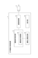
- FIG. 1 is a diagram showing a machine tool control device according to an embodiment of the present disclosure
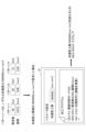
- FIG. It is a figure for demonstrating the vibration control which concerns on the said embodiment. It is a figure showing the 1st example of vibration control concerning the above-mentioned embodiment. It is a figure which shows the 2nd example of the vibration control which concerns on the said embodiment.
- FIG. 1 is a diagram showing a control device 1 for a machine tool according to this embodiment.
- a control device 1 for a machine tool according to this embodiment includes at least one main shaft for relatively rotating a cutting tool (hereinafter referred to as a tool) and a work, and at least one feed shaft for relatively moving the tool with respect to the work. , the workpiece is cut by the tool.
- FIG. 1 shows only the motor 3 for driving one feed shaft.
- the machine tool control device 1 performs swing cutting (hereinafter also referred to as vibration cutting) by operating the main shaft and the feed shaft. That is, the control device 1 of the machine tool performs cutting while relatively rotating the tool and the work and relatively swinging (hereinafter also referred to as vibration) the tool and the work.
- the tool path which is the trajectory of the tool, is set such that the current path partially overlaps the previous path, and the portion machined by the previous path is included in the current path.
- air cutting occurs in which the cutting edge of the tool separates from the surface of the workpiece, and chips that are continuously generated by the cutting process are reliably shredded.
- this embodiment not only is the tool moved in the feed direction while swinging it relative to the workpiece rotating around the central axis, but also the tool T rotates around the central axis of the workpiece and the workpiece moves relative to the tool. It can also be applied to a configuration in which it moves in the feed direction. Further, this embodiment can be applied to both outer diameter machining and inner diameter machining of a work. Furthermore, this embodiment can be used not only when a plurality of feed axes (Z-axis and X-axis) are required due to the workpiece having a tapered portion or arc-shaped portion on the machining surface, but also when the workpiece has a columnar or cylindrical shape. It is applicable even when one specific axis (Z-axis) is sufficient.
- the machine tool control device 1 includes, for example, memories such as ROM (read only memory) and RAM (random access memory), a CPU (control processing unit), and a communication control unit, which are connected to each other via a bus. It is configured using a computer. As shown in FIG. 1, a machine tool control device 1 includes a vibration condition setting unit 11, a vibration condition limiting unit 12, a vibration upper limit setting unit 13, a vibration control unit 14, and a display unit 15. , the function and operation of each part can be achieved by the cooperation of the CPU mounted on the computer, the memory, and the control program stored in the memory.
- memories such as ROM (read only memory) and RAM (random access memory)
- CPU control processing unit
- a communication control unit which are connected to each other via a bus. It is configured using a computer.
- a machine tool control device 1 includes a vibration condition setting unit 11, a vibration condition limiting unit 12, a vibration upper limit setting unit 13, a vibration control unit 14, and a display unit 15.
- the function and operation of each part can
- a host computer such as a CNC (Computer Numerical Controller), a PLC (Programmable Logic Controller), or the like is connected to the control device 1 of the machine tool.
- a machining program and workpiece machining conditions such as rotation speed and feed speed are input to the control device 1 of the machine tool from these host computers.
- the workpiece machining conditions include the relative rotation speed of the workpiece and tool around the central axis of the workpiece, the relative feed speed of the tool and workpiece, the position command of the feed axis, and the like.
- the CPU in the control device 1 of the machine tool may be configured to read out the rotation speed and the feed speed as machining conditions from the input machining program and output them to the vibration control unit 14.
- the position command generating section and the like in the section 14 may be provided in the host computer.
- the vibration condition setting unit 11 sets a vibration condition including at least one of a frequency parameter consisting of a vibration frequency or a vibration frequency magnification, an amplitude parameter consisting of a vibration amplitude or a vibration amplitude magnification, and a vibration direction.
- the vibration condition setting unit 11 sets the above-described vibration conditions based on the machining program, machining conditions, and the like input to the control device 1 of the machine tool under the restrictions of the vibration condition limiting unit 12, which will be described later.
- the vibration conditions set by the vibration condition setting unit 11 are output to the vibration control unit 14, which will be described later.
- the vibration frequency multiplier is a frequency parameter obtained by dividing the vibration frequency by the spindle speed.
- the vibration amplitude multiplier is an amplitude parameter obtained by dividing the vibration amplitude by 1/2 of the feed amount of the feed shaft per rotation of the main shaft.
- the vibration direction is represented, for example, by an inclination ⁇ with respect to the central axis (Z-axis direction) of the work (see FIG. 4 described later).
- the vibration upper limit setting unit 13 sets the upper limit of the vibration parameter including at least one of the vibration frequency, vibration amplitude, vibration speed, vibration acceleration, and vibration jerk determined by the vibration condition to the vibration frequency and vibration direction. set according to one or both of The upper limit value of the vibration parameter set by the vibration upper limit setting unit 13 is output to the vibration condition limiting unit 12, which will be described later.
- the vibration upper limit setting unit 13 may set the upper limit value of the vibration parameter so that it decreases stepwise or continuously as the vibration frequency increases. preferable. This is because the higher the vibration frequency, the easier it is for the machine tool to shake.
- the vibration upper limit setting unit 13 sets the upper limit of vibration parameters such as the upper limit of acceleration at intervals of 10 Hz, such as vibration frequencies of 0 to 10 Hz, 10 to 20 Hz, 20 to 30 Hz, and so on, as the vibration frequency increases. It is set to be small (see FIG. 3 described later).
- the vibration of the entire machine tool due to vibration control of the control axis is caused by vibration frequency, amplitude, speed, acceleration, and jerk.
- the amplitude, velocity, acceleration, and jerk of these vibrations are affected by the vibration frequency.
- the upper limits of vibration parameters such as vibration frequency, vibration amplitude, vibration velocity, vibration acceleration, and vibration jerk are set according to the vibration frequency.
- the vibration upper limit setting unit 13 preferably sets the upper limit of the vibration parameter to a smaller value than for other frequencies. For example, when the resonance frequency unique to the machine tool is 40 to 50 Hz, the vibration upper limit setting unit 13 sets the upper limit value of the vibration parameter to be smaller than other vibration frequencies less than 40 Hz or greater than 50 Hz. set.
- the vibration frequency in vibration control of the control axis is a frequency corresponding to the resonance frequency unique to the machine tool
- the machine tool vibrates more greatly in synchronization with the vibration of the control axis.
- the vibration frequency corresponds to the resonance frequency
- the upper limit value of the vibration parameter is set smaller, so the vibration condition is set based on the upper limit value of the vibration parameter thus set. As a result, vibration of the entire machine tool is more effectively suppressed.
- the vibration frequency band having a certain width may include the resonance frequency unique to the machine tool. At this time, the width of the vibration frequency band is appropriately set.
- the vibration upper limit setting unit 13 preferably sets the upper limit of the vibration parameter so that it decreases stepwise or continuously as the tilt of the vibration direction with respect to the central axis direction of the workpiece increases.
- the inclination ⁇ of the oscillation direction (hereinafter also referred to as vibration direction) with respect to the central axis (Z-axis direction) of the work is 0° to 10°, 10° to 20°, 20 to 30°.
- the upper limit values of the vibration parameters such as the acceleration upper limit value are set to decrease as the tilt ⁇ of the vibration direction with respect to the Z-axis direction increases (see FIG. 4 described later).
- many heavy objects such as servo motors are arranged in the X-axis direction (the radial direction of the work) perpendicular to the Z-axis direction (the direction of the central axis of the work), so the X-axis is more controlled than the Z-axis.
- the amount of shaft vibration is large and the inertia is large. Since the inertia of the control shaft differs depending on the machine tool, the vibration of the entire machine tool that occurs when the control shaft is vibrated is affected by the vibration direction, which indicates the ratio of the vibration amount of the control shaft.
- the upper limit values of vibration parameters such as vibration acceleration and vibration jerk are set according to the vibration direction, specifically based on the inclination ⁇ of the vibration direction with respect to the Z axis.
- the magnitude of the inertia of the Z-axis and the X-axis differs depending on the mechanical configuration, so the Z-axis may have greater inertia than the X-axis.
- the inclination ⁇ of the vibration direction is set at intervals of 10°, such as 0° to 10°, 10° to 20°, and 20 to 30°.
- the vibration upper limit setting unit 13 preferably sets the upper limit value of the vibration parameter to different values depending on whether the vibration direction is parallel or non-parallel to the driving direction of each control axis.
- the case where the vibration direction is parallel to the drive direction of each control axis is when only one control axis is vibrated, and the non-parallel case is when a plurality of drive axes are vibrated in cooperation. is.
- the vibration upper limit setting unit 13 may set the vibration frequency as the upper limit value of the vibration parameter.
- the vibration frequency increases, the vibration of the machine tool also increases. Therefore, it is preferable to set the upper limit value of the vibration frequency smaller as the tilt of the vibration direction with respect to the central axis direction of the workpiece increases.
- the vibration upper limit setting unit 13 measures the vibration of the machine tool when the vibration control of the control axis is actually executed in advance, not only visually by the user but also by various sensors, etc., and based on these results, sets the vibration parameter. An upper limit can be determined.
- the vibration condition limiting section 12 limits the vibration condition set by the vibration condition setting section 11 based on the upper limit value of the vibration parameter set by the vibration upper limit setting section 13 . Specifically, the vibration condition limiting unit 12 acquires the frequency parameter and the vibration direction from the vibration condition setting unit 11, and limits the vibration condition using the upper limit value of the vibration parameter corresponding to the acquired frequency parameter and vibration direction.
- the vibration condition limiting unit 12 preferably limits the vibration conditions set by the vibration condition setting unit 11 so that the upper limit values of the vibration parameters corresponding to the obtained frequency parameter and vibration direction are not exceeded.
- the vibration condition limiter 12 clamps the vibration frequency, vibration amplitude, etc. within a range not exceeding the upper limit of the vibration parameter.
- the vibration condition limiter 12 stops the machining program by, for example, issuing an alarm (warning) when the upper limit value of the vibration parameter is exceeded.
- the vibration control unit 14 performs vibration control on the control axis based on the vibration conditions set by the vibration condition setting unit 11 under the restrictions of the vibration condition limiting unit 12 .
- the vibration control unit 14 includes various functional units (any (also not shown).
- the position command generator generates a position command as a movement command for the motor 3 based on the machining program and machining conditions input to the control device 1 of the machine tool. Specifically, the position command generator generates a position command (movement command) for each feed axis based on the relative rotational speed of the work and the tool about the central axis of the work and the relative feed speed of the tool and the work. Generate.
- the vibration command generator generates a vibration command.
- the vibration command generator generates a vibration command from the vibration conditions set by the vibration condition setting unit 11 described above.
- the superimposed command generation unit calculates a position deviation, which is the difference between the position feedback based on the position detection by the encoder of the motor 3 of the feed shaft and the position command, and generates the vibration command generation unit for the calculated position deviation.
- a superimposed command is generated by superimposing the vibration command thus obtained.
- the vibration command may be superimposed on the position command instead of the position deviation.
- the learning control unit calculates the correction amount of the superimposed command based on the superimposed command, and adds the calculated correction amount to the superimposed command to correct the superimposed command.
- the learning control unit has a memory, stores the vibration phase and the correction amount in the memory in association with each other within one cycle or a plurality of cycles of vibration, and the timing at which the phase delay of the vibration operation according to the response of the motor 3 can be compensated. , the superimposition command stored in the memory is read out and output as a correction amount. If the vibration phase for which the correction amount is to be output does not exist in the vibration phases stored in the memory, the correction amount to be output may be calculated based on the correction amount having the close vibration phase. In general, the higher the vibration frequency, the greater the position deviation with respect to the vibration command. Therefore, by performing the correction by this learning control unit, it is possible to improve the ability to follow the periodic vibration command.
- the position/speed control unit generates a torque command for the motor 3 that drives the feed shaft based on the superimposed command after addition of the correction amount, and controls the motor 3 with the generated torque command. As a result, machining is performed while the tool T and the work W are relatively vibrated.
- the display unit 15 displays the upper limit value of the vibration parameter set by the vibration upper limit setting unit 13 and the vibration condition limited by the vibration condition limiting unit 12 based on the upper limit value and set by the vibration condition setting unit 11. display on the screen. In addition to various setting parameters, the display unit 15 also displays a machining program input to the control device 1 of the machine tool. As a result, the user can set the upper limit value of the vibration parameter and the vibration condition using an input unit (not shown) while checking the display screen.
- the vibration condition limiting unit 12 clamps the vibration amplitude at 0.015 mm while keeping the vibration frequency at 40 Hz, for example, so that the vibration acceleration does not exceed the upper limit of 1800000 [mm/min 2 ]. Then, the vibration condition setting unit 11 sets a vibration frequency of 40 Hz and a clamped vibration amplitude of 0.015 mm as vibration conditions. As a result, the vibration acceleration becomes the upper limit value of 1800000 [mm/min 2 ], and the vibration occurring in the entire machine tool is reliably suppressed.
- clamping is not limited to the vibration amplitude, and the vibration frequency may be clamped, or both the vibration amplitude and the vibration frequency may be clamped.
- the method of limiting the vibration condition is not limited to clamping, and for example, when a vibration parameter such as vibration acceleration exceeds the upper limit value, an alarm or the like may be issued to stop the machining program.
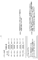
- FIG. 3 is a diagram showing a first example of vibration control according to this embodiment.
- a first example shown in FIG. 3 is an example in which the upper limit value of the vibration acceleration is set according to the vibration frequency. Specifically, as shown in the display unit 15 in FIG. 2 ], 1900000 [mm/min2] at 10 to 20 Hz, 1800000 [mm/min2] at 20 to 30 Hz, 1600000 [mm/min2] at 30 to 40 Hz, 40 to 50 Hz
- the upper limit value of the vibration acceleration is set for each vibration frequency band at intervals of 10 Hz, such as 1000000 [mm/min 2 ] for 50 to 60 Hz and 1500000 [mm/min 2 ] for 50 to 60 Hz.
- the acceleration upper limit value is set to decrease as the vibration frequency increases, and the lowest acceleration upper limit value is set at 40 to 50 Hz, which corresponds to the resonance frequency of the machine tool. ing.
- the vibration cutting specified by the machining program input to the control device 1 of the machine tool has a vibration frequency of 25 Hz and a vibration amplitude of 0.1 mm. is.
- the vibration acceleration at the vibration frequency of 25 Hz and the vibration amplitude of 0.1 mm is calculated by the above formula (1), it exceeds the vibration acceleration upper limit of 1800000 [mm/min 2 ] at the vibration frequency of 25 Hz. Therefore, in this first example, the vibration amplitude is changed to a smaller value while the vibration frequency remains at 25 Hz. Clamp the vibration amplitude to an amplitude of 0.00384 mm. In this way, by setting the vibration condition so as not to exceed the vibration acceleration upper limit value, the vibration occurring in the entire machine tool can be reliably suppressed.
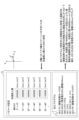
- FIG. 4 is a diagram showing a second example of vibration control according to this embodiment.
- a second example shown in FIG. 4 is an example in which the upper limit value of the vibration acceleration is set according to the vibration direction.
- the upper limit of vibration acceleration is set for each tilt angle band at 10° intervals, such as 1400000 [mm/min2] for 40 to 50° and 1100000 [mm/min2] for 50 to 60°. ing.
- the upper limit of acceleration is set to decrease as the tilt of the vibration direction with respect to the Z axis increases.
- the vibration cutting specified by the machining program input to the machine tool controller 1 has a vibration frequency of 25 Hz and a vibration amplitude of 0.04 mm. is.
- the movement direction of the movement command specified by the machining program is determined to be 45° from the X coordinate position and Z coordinate position specified by G00 and G01.
- the vibration direction is the same as the movement direction of the movement command, the inclination ⁇ of the vibration direction with respect to the Z axis is 45°.
- the vibration acceleration upper limit value when the inclination ⁇ of the vibration direction with respect to the Z axis is 45° is 1400000 [mm/min 2 ]. exceed. Therefore, in this second example, the vibration amplitude is changed to a smaller value while the vibration frequency remains at 25 Hz. Clamp the vibration amplitude to an amplitude of 0.0299 mm. In this way, by setting the vibration condition so as not to exceed the vibration acceleration upper limit value, the vibration occurring in the entire machine tool can be reliably suppressed.
- the machine tool control device 1 sets vibration conditions including at least one of a frequency parameter consisting of a vibration frequency or a vibration frequency magnification, an amplitude parameter consisting of a vibration amplitude or a vibration amplitude magnification, and a vibration direction.
- a vibration condition setting unit 11 sets upper limits of vibration parameters including at least one of vibration frequency, vibration amplitude, vibration speed, vibration acceleration, and vibration jerk, which are determined by the vibration conditions, to the vibration frequency and the vibration direction.
- a vibration upper limit setting unit 13 is provided for setting according to one or both.
- the machine tool control device 1 includes a vibration condition limiting unit 12 that limits the vibration condition set by the vibration condition setting unit 11 based on the upper limit value of the vibration parameter, and the vibration condition limiting unit 12 and a vibration control unit 14 that controls vibration of the control shaft based on the vibration condition limited by the.
- the vibration of the entire machine tool due to vibration control of the control axis is mainly caused by vibration parameters such as vibration acceleration and jerk, and these vibration parameters are affected by vibration frequency and vibration direction.
- the vibration condition setting unit 11 sets the upper limit value of the vibration parameter set by the vibration upper limit setting unit 13 according to one or both of the vibration frequency and the vibration direction.
- the vibration condition is limited by the vibration condition limiter 12 . Therefore, in vibration control of the control axis, it is possible to set vibration conditions that do not exceed the upper limit values of the vibration parameters set according to the vibration frequency and vibration direction, and it is possible to reliably suppress the shaking that occurs in the entire machine tool. .
- the vibration upper limit setting unit 13 of the present embodiment sets the upper limit of the vibration parameter so that it decreases stepwise or continuously as the vibration frequency increases.
- the higher the vibration frequency the easier it is for the machine tool to shake.
- it is possible to set a more appropriate upper limit value for the vibration parameter according to the vibration frequency. can be suppressed to
- the vibration upper limit setting unit 13 of the present embodiment sets the upper limit value of the vibration parameter to different values depending on whether the vibration direction is parallel to or non-parallel to the driving direction of each control axis. As a result, the vibration of the entire machine tool may be more effectively suppressed.
- the vibration upper limit setting unit 13 of the present embodiment decreases or increases the upper limit value of the vibration parameter stepwise or continuously as the inclination ⁇ of the vibration direction with respect to the central axis direction (Z-axis) of the workpiece increases. set as Depending on the machine configuration, the greater the inclination ⁇ of the vibration direction with respect to the central axis direction (Z-axis) of the workpiece, the easier or less likely the machine tool will swing. Since the upper limit value of the parameter can be set, it is possible to more reliably suppress the shaking that occurs in the entire machine tool.
- the vibration upper limit setting unit 13 of the present embodiment sets the upper limit of the vibration parameter to a value smaller than that for other frequencies when the vibration frequency corresponds to the resonance frequency unique to the machine tool. .
- the vibration frequency corresponds to the resonance frequency of the machine tool
- the machine tool tends to shake. Shaking that occurs in the entire machine tool can be suppressed more reliably.
- the vibration condition limiting section 12 limits the vibration conditions set by the vibration condition setting section 11 so that the upper limit of the vibration parameter is not exceeded. As a result, according to the present embodiment, it is possible to reliably avoid exceeding the upper limit value of the vibration parameter, so that it is possible to more reliably suppress vibration occurring in the entire machine tool.
- the present invention is applied to vibration cutting, but it is not limited to this. It can also be applied to a control device for a machine tool that processes a workpiece by controlling the control axis to move while vibrating the control axis, such as crankpin machining.
- the present invention is not limited to this.
- the upper limit of the vibration parameter may be set according to both the vibration frequency and the vibration direction.
- the machine tool control device 1 is configured to include the display unit 15, but the present invention is not limited to this.
- the control device 1 of the machine tool may not have the display section 15, and the display section 15 may be provided in the host computer or the like.
Landscapes
- Engineering & Computer Science (AREA)
- Physics & Mathematics (AREA)
- General Physics & Mathematics (AREA)
- Automation & Control Theory (AREA)
- Mechanical Engineering (AREA)
- Human Computer Interaction (AREA)
- Manufacturing & Machinery (AREA)
- Geometry (AREA)
- Numerical Control (AREA)
- Automatic Control Of Machine Tools (AREA)
Abstract
Description
[数1]
振動加速度=α×(振動振幅)×(振動周波数)2 ・・・式(1)
3 モータ
11 振動条件設定部
12 振動条件制限部
13 振動上限設定部
14 振動制御部
15 表示部
Claims (6)
- 工具とワークを相対的に振動させながら加工する工作機械の制御装置であって、
振動周波数又は振動周波数倍率からなる周波数パラメータ、振動振幅又は振動振幅倍率からなる振幅パラメータ、及び振動方向のうち少なくとも一つを含む振動条件を設定する振動条件設定部と、
前記振動条件により決定される、振動周波数、振動振幅、振動速度、振動加速度、及び振動加加速度のうち少なくとも一つを含む振動パラメータの上限値を、振動周波数及び振動方向の一方又は両方に応じて設定する振動上限設定部と、
前記振動パラメータの上限値に基づいて、前記振動条件設定部で設定される振動条件を制限する振動条件制限部と、
前記振動条件制限部により制限された振動条件に基づいて、制御軸を振動制御する振動制御部と、を備える、工作機械の制御装置。 - 前記振動上限設定部は、前記振動パラメータの上限値を、前記振動周波数が大きくなるに従い段階的に又は連続的に小さくなるように設定する、請求項1に記載の工作機械の制御装置。
- 前記振動上限設定部は、前記振動パラメータの上限値を、前記振動方向が各制御軸の駆動方向と平行な場合と非平行な場合とで、それぞれ異なる値に設定する、請求項1又は2に記載の工作機械の制御装置。
- 前記振動上限設定部は、前記振動パラメータの上限値を、前記ワークの中心軸方向に対する前記振動方向の傾きが大きくなるに従い段階的に又は連続的に小さく又は大きくなるように設定する、請求項1から3いずれかに記載の工作機械の制御装置。
- 前記振動上限設定部は、前記振動周波数が前記工作機械固有の共振周波数に相当する周波数の場合に、他の周波数の場合と比べて前記振動パラメータの上限値をより小さい値に設定する、請求項1から4いずれかに記載の工作機械の制御装置。
- 前記振動条件制限部は、前記振動パラメータの上限値を超えないように、前記振動条件設定部で設定される振動条件を制限する、請求項1から5いずれかに記載の工作機械の制御装置。
Priority Applications (5)
| Application Number | Priority Date | Filing Date | Title |
|---|---|---|---|
| PCT/JP2021/027845 WO2023007602A1 (ja) | 2021-07-28 | 2021-07-28 | 工作機械の制御装置 |
| DE112021007678.7T DE112021007678T5 (de) | 2021-07-28 | 2021-07-28 | Steuervorrichtung für eine Werkzeugmaschine |
| CN202180100763.1A CN117693408A (zh) | 2021-07-28 | 2021-07-28 | 机床的控制装置 |
| US18/573,493 US20240293906A1 (en) | 2021-07-28 | 2021-07-28 | Control device for machine tool |
| JP2023537804A JP7667280B2 (ja) | 2021-07-28 | 2021-07-28 | 工作機械の制御装置 |
Applications Claiming Priority (1)
| Application Number | Priority Date | Filing Date | Title |
|---|---|---|---|
| PCT/JP2021/027845 WO2023007602A1 (ja) | 2021-07-28 | 2021-07-28 | 工作機械の制御装置 |
Publications (1)
| Publication Number | Publication Date |
|---|---|
| WO2023007602A1 true WO2023007602A1 (ja) | 2023-02-02 |
Family
ID=85086451
Family Applications (1)
| Application Number | Title | Priority Date | Filing Date |
|---|---|---|---|
| PCT/JP2021/027845 Ceased WO2023007602A1 (ja) | 2021-07-28 | 2021-07-28 | 工作機械の制御装置 |
Country Status (5)
| Country | Link |
|---|---|
| US (1) | US20240293906A1 (ja) |
| JP (1) | JP7667280B2 (ja) |
| CN (1) | CN117693408A (ja) |
| DE (1) | DE112021007678T5 (ja) |
| WO (1) | WO2023007602A1 (ja) |
Citations (3)
| Publication number | Priority date | Publication date | Assignee | Title |
|---|---|---|---|---|
| WO2015146946A1 (ja) * | 2014-03-26 | 2015-10-01 | シチズンホールディングス株式会社 | 工作機械の制御装置及びこの制御装置を備えた工作機械 |
| WO2016084171A1 (ja) * | 2014-11-26 | 2016-06-02 | 三菱電機株式会社 | 数値制御装置 |
| JP2021003802A (ja) * | 2019-06-25 | 2021-01-14 | ファナック株式会社 | 数値制御装置、制御プログラム及び制御方法 |
Family Cites Families (18)
| Publication number | Priority date | Publication date | Assignee | Title |
|---|---|---|---|---|
| US6526566B1 (en) * | 1997-11-14 | 2003-02-25 | National Instruments Corporation | Graphical programming system and method including nodes for programmatically accessing data sources and targets |
| JP2004188541A (ja) * | 2002-12-11 | 2004-07-08 | Yamazaki Mazak Corp | 工作機械の送り軸パラメータ調整システム |
| JP2007044849A (ja) | 2005-08-12 | 2007-02-22 | Utsunomiya Univ | 切削方法 |
| US8924269B2 (en) * | 2006-05-13 | 2014-12-30 | Sap Ag | Consistent set of interfaces derived from a business object model |
| US7840904B2 (en) * | 2006-08-04 | 2010-11-23 | National Instruments Corporation | Execution target structure node for a graphical program |
| US8612870B2 (en) * | 2006-08-04 | 2013-12-17 | National Instruments Corporation | Graphically specifying and indicating targeted execution in a graphical program |
| JP5752928B2 (ja) * | 2010-11-30 | 2015-07-22 | 住友理工株式会社 | 能動型振動騒音抑制装置 |
| EP2495622B1 (de) * | 2011-03-03 | 2017-06-07 | Siemens Aktiengesellschaft | Verfahren zum Betrieb eines Automatisierungssystems, Computerprogramm zur Implementierung des Verfahrens und Computersystem mit einem solchen Computerprogramm |
| US9501449B2 (en) * | 2013-09-10 | 2016-11-22 | Sviral, Inc. | Method, apparatus, and computer-readable medium for parallelization of a computer program on a plurality of computing cores |
| CN105938329B (zh) * | 2016-04-08 | 2019-02-22 | 北京稳力科技有限公司 | 一种用于数控机床动态特性仿真及其与数控系统集成的方法 |
| JP6875810B2 (ja) * | 2016-09-13 | 2021-05-26 | シチズン時計株式会社 | 工作機械およびその制御装置 |
| JP6724831B2 (ja) * | 2017-03-16 | 2020-07-15 | 株式会社安川電機 | コントロールシステム、コントローラ及び制御方法 |
| JP6503000B2 (ja) * | 2017-04-18 | 2019-04-17 | ファナック株式会社 | 揺動切削を行う工作機械の制御装置 |
| US20220184810A1 (en) * | 2019-04-02 | 2022-06-16 | Universal Robots A/S | Robot arm safety system with runtime adaptable safety limits |
| EP3976323B1 (en) * | 2019-05-29 | 2024-10-09 | Universal Robots A/S | Control of a multipurpose robot arm |
| JP7238673B2 (ja) * | 2019-07-30 | 2023-03-14 | ブラザー工業株式会社 | 数値制御装置及び制御方法 |
| CA3177620A1 (en) * | 2021-05-06 | 2022-11-06 | Strong Force Iot Portfolio 2016, Llc | Quantum, biological, computer vision, and neural network systems for industrial internet of things |
| WO2023016616A1 (en) * | 2021-08-13 | 2023-02-16 | Universal Robots A/S | A robot system for anomaly detection |
-
2021
- 2021-07-28 WO PCT/JP2021/027845 patent/WO2023007602A1/ja not_active Ceased
- 2021-07-28 DE DE112021007678.7T patent/DE112021007678T5/de active Pending
- 2021-07-28 JP JP2023537804A patent/JP7667280B2/ja active Active
- 2021-07-28 CN CN202180100763.1A patent/CN117693408A/zh active Pending
- 2021-07-28 US US18/573,493 patent/US20240293906A1/en active Pending
Patent Citations (3)
| Publication number | Priority date | Publication date | Assignee | Title |
|---|---|---|---|---|
| WO2015146946A1 (ja) * | 2014-03-26 | 2015-10-01 | シチズンホールディングス株式会社 | 工作機械の制御装置及びこの制御装置を備えた工作機械 |
| WO2016084171A1 (ja) * | 2014-11-26 | 2016-06-02 | 三菱電機株式会社 | 数値制御装置 |
| JP2021003802A (ja) * | 2019-06-25 | 2021-01-14 | ファナック株式会社 | 数値制御装置、制御プログラム及び制御方法 |
Also Published As
| Publication number | Publication date |
|---|---|
| DE112021007678T5 (de) | 2024-04-11 |
| US20240293906A1 (en) | 2024-09-05 |
| JPWO2023007602A1 (ja) | 2023-02-02 |
| CN117693408A (zh) | 2024-03-12 |
| JP7667280B2 (ja) | 2025-04-22 |
Similar Documents
| Publication | Publication Date | Title |
|---|---|---|
| JP5908342B2 (ja) | 工作機械の加工振動抑制方法及び加工振動抑制装置 | |
| JP6416218B2 (ja) | 工作機械の制御装置及びこの制御装置を備えた工作機械 | |
| JP6416217B2 (ja) | 工作機械の制御装置及びこの制御装置を備えた工作機械 | |
| JP6763917B2 (ja) | 工作機械の制御装置 | |
| JP6715271B2 (ja) | 工作機械の制御装置、工作機械 | |
| WO2017051745A1 (ja) | 工作機械の制御装置及びこの制御装置を備えた工作機械 | |
| JP7044734B2 (ja) | サーボ制御装置 | |
| JP6599920B2 (ja) | 揺動切削を行う工作機械の制御装置 | |
| JP7195110B2 (ja) | 工作機械及び制御装置 | |
| JP7007531B1 (ja) | 情報処理装置、工作機械の制御装置、及びコンピュータプログラム | |
| JP7522180B2 (ja) | 工作機械の制御装置 | |
| JP2016181193A (ja) | 位置決め装置のパラメータ設定方法、及び位置決め装置 | |
| CN119855677A (zh) | 机床的控制装置以及机床的显示装置 | |
| JP7036786B2 (ja) | 数値制御装置、プログラム及び制御方法 | |
| WO2022269751A1 (ja) | 工作機械の制御装置 | |
| WO2023007678A1 (ja) | 工作機械の制御装置及び工作機械の制御システム | |
| WO2020084771A1 (ja) | 数値制御装置、工作機械および数値制御方法 | |
| JP7525593B2 (ja) | 工作機械の制御装置、制御方法 | |
| JP7280310B2 (ja) | 数値制御装置 | |
| WO2023007602A1 (ja) | 工作機械の制御装置 | |
| JP2016190305A (ja) | 位置決め装置のパラメータ設定方法、及びパラメータ設定装置、並びにこのパラメータ設定装置を備えた位置決め装置 | |
| JP7633286B2 (ja) | 制御装置及び計算装置 | |
| JP7649757B2 (ja) | 切削加工制御装置及び切削加工装置 | |
| WO2023139743A1 (ja) | 情報処理装置、工作機械の制御装置、及びコンピュータプログラム | |
| WO2022009925A1 (ja) | 工作機械の制御装置 |
Legal Events
| Date | Code | Title | Description |
|---|---|---|---|
| 121 | Ep: the epo has been informed by wipo that ep was designated in this application |
Ref document number: 21951810 Country of ref document: EP Kind code of ref document: A1 |
|
| WWE | Wipo information: entry into national phase |
Ref document number: 2023537804 Country of ref document: JP |
|
| WWE | Wipo information: entry into national phase |
Ref document number: 18573493 Country of ref document: US |
|
| WWE | Wipo information: entry into national phase |
Ref document number: 112021007678 Country of ref document: DE |
|
| WWE | Wipo information: entry into national phase |
Ref document number: 202180100763.1 Country of ref document: CN |
|
| 122 | Ep: pct application non-entry in european phase |
Ref document number: 21951810 Country of ref document: EP Kind code of ref document: A1 |