WO2023007571A1 - 電気機器配線部品 - Google Patents
電気機器配線部品 Download PDFInfo
- Publication number
- WO2023007571A1 WO2023007571A1 PCT/JP2021/027658 JP2021027658W WO2023007571A1 WO 2023007571 A1 WO2023007571 A1 WO 2023007571A1 JP 2021027658 W JP2021027658 W JP 2021027658W WO 2023007571 A1 WO2023007571 A1 WO 2023007571A1
- Authority
- WO
- WIPO (PCT)
- Prior art keywords
- electrical equipment
- wiring component
- housing
- equipment wiring
- lid
- Prior art date
- Legal status (The legal status is an assumption and is not a legal conclusion. Google has not performed a legal analysis and makes no representation as to the accuracy of the status listed.)
- Ceased
Links
Images








Classifications
-
- H—ELECTRICITY
- H05—ELECTRIC TECHNIQUES NOT OTHERWISE PROVIDED FOR
- H05K—PRINTED CIRCUITS; CASINGS OR CONSTRUCTIONAL DETAILS OF ELECTRIC APPARATUS; MANUFACTURE OF ASSEMBLAGES OF ELECTRICAL COMPONENTS
- H05K3/00—Apparatus or processes for manufacturing printed circuits
- H05K3/46—Manufacturing multilayer circuits
- H05K3/4602—Manufacturing multilayer circuits characterized by a special circuit board as base or central core whereon additional circuit layers are built or additional circuit boards are laminated
- H05K3/4608—Manufacturing multilayer circuits characterized by a special circuit board as base or central core whereon additional circuit layers are built or additional circuit boards are laminated comprising an electrically conductive base or core
-
- H—ELECTRICITY
- H02—GENERATION; CONVERSION OR DISTRIBUTION OF ELECTRIC POWER
- H02G—INSTALLATION OF ELECTRIC CABLES OR LINES, OR OF COMBINED OPTICAL AND ELECTRIC CABLES OR LINES
- H02G5/00—Installations of bus-bars
- H02G5/06—Totally-enclosed installations, e.g. in metal casings
-
- H—ELECTRICITY
- H05—ELECTRIC TECHNIQUES NOT OTHERWISE PROVIDED FOR
- H05K—PRINTED CIRCUITS; CASINGS OR CONSTRUCTIONAL DETAILS OF ELECTRIC APPARATUS; MANUFACTURE OF ASSEMBLAGES OF ELECTRICAL COMPONENTS
- H05K1/00—Printed circuits
- H05K1/02—Details
- H05K1/0213—Electrical arrangements not otherwise provided for
- H05K1/0263—High current adaptations, e.g. printed high current conductors or using auxiliary non-printed means; Fine and coarse circuit patterns on one circuit board
-
- H—ELECTRICITY
- H05—ELECTRIC TECHNIQUES NOT OTHERWISE PROVIDED FOR
- H05K—PRINTED CIRCUITS; CASINGS OR CONSTRUCTIONAL DETAILS OF ELECTRIC APPARATUS; MANUFACTURE OF ASSEMBLAGES OF ELECTRICAL COMPONENTS
- H05K3/00—Apparatus or processes for manufacturing printed circuits
- H05K3/0011—Working of insulating substrates or insulating layers
- H05K3/0014—Shaping of the substrate, e.g. by moulding
-
- H—ELECTRICITY
- H05—ELECTRIC TECHNIQUES NOT OTHERWISE PROVIDED FOR
- H05K—PRINTED CIRCUITS; CASINGS OR CONSTRUCTIONAL DETAILS OF ELECTRIC APPARATUS; MANUFACTURE OF ASSEMBLAGES OF ELECTRICAL COMPONENTS
- H05K5/00—Casings, cabinets or drawers for electric apparatus
- H05K5/02—Details
- H05K5/03—Covers
-
- H—ELECTRICITY
- H05—ELECTRIC TECHNIQUES NOT OTHERWISE PROVIDED FOR
- H05K—PRINTED CIRCUITS; CASINGS OR CONSTRUCTIONAL DETAILS OF ELECTRIC APPARATUS; MANUFACTURE OF ASSEMBLAGES OF ELECTRICAL COMPONENTS
- H05K7/00—Constructional details common to different types of electric apparatus
- H05K7/02—Arrangements of circuit components or wiring on supporting structure
- H05K7/06—Arrangements of circuit components or wiring on supporting structure on insulating boards, e.g. wiring harnesses
-
- H—ELECTRICITY
- H02—GENERATION; CONVERSION OR DISTRIBUTION OF ELECTRIC POWER
- H02G—INSTALLATION OF ELECTRIC CABLES OR LINES, OR OF COMBINED OPTICAL AND ELECTRIC CABLES OR LINES
- H02G3/00—Installations of electric cables or lines or protective tubing therefor in or on buildings, equivalent structures or vehicles
- H02G3/02—Details
- H02G3/08—Distribution boxes; Connection or junction boxes
- H02G3/16—Distribution boxes; Connection or junction boxes structurally associated with support for line-connecting terminals within the box
-
- H—ELECTRICITY
- H05—ELECTRIC TECHNIQUES NOT OTHERWISE PROVIDED FOR
- H05K—PRINTED CIRCUITS; CASINGS OR CONSTRUCTIONAL DETAILS OF ELECTRIC APPARATUS; MANUFACTURE OF ASSEMBLAGES OF ELECTRICAL COMPONENTS
- H05K2201/00—Indexing scheme relating to printed circuits covered by H05K1/00
- H05K2201/03—Conductive materials
- H05K2201/0332—Structure of the conductor
- H05K2201/0335—Layered conductors or foils
- H05K2201/0355—Metal foils
-
- H—ELECTRICITY
- H05—ELECTRIC TECHNIQUES NOT OTHERWISE PROVIDED FOR
- H05K—PRINTED CIRCUITS; CASINGS OR CONSTRUCTIONAL DETAILS OF ELECTRIC APPARATUS; MANUFACTURE OF ASSEMBLAGES OF ELECTRICAL COMPONENTS
- H05K2201/00—Indexing scheme relating to printed circuits covered by H05K1/00
- H05K2201/09—Shape and layout
- H05K2201/09009—Substrate related
- H05K2201/09118—Moulded substrate
-
- H—ELECTRICITY
- H05—ELECTRIC TECHNIQUES NOT OTHERWISE PROVIDED FOR
- H05K—PRINTED CIRCUITS; CASINGS OR CONSTRUCTIONAL DETAILS OF ELECTRIC APPARATUS; MANUFACTURE OF ASSEMBLAGES OF ELECTRICAL COMPONENTS
- H05K2201/00—Indexing scheme relating to printed circuits covered by H05K1/00
- H05K2201/10—Details of components or other objects attached to or integrated in a printed circuit board
- H05K2201/10227—Other objects, e.g. metallic pieces
- H05K2201/10272—Busbars, i.e. thick metal bars mounted on the printed circuit board [PCB] as high-current conductors
Definitions
- This application relates to electrical equipment wiring components.
- the present application discloses a technique for solving the above problems, and aims to obtain a highly reliable electrical equipment wiring component that prevents leakage current.
- the electrical equipment wiring component disclosed in the present application includes a plurality of busbars, and both ends of each of the plurality of busbars are exposed and buried inside with a gap between each other, and an intermediate portion of each of the plurality of busbars is exposed.
- a housing made of resin having a space formed with an opening, and a filling made of elastomer filled in the space and covering the entire circumference of the bus bar at least at a boundary portion between the intermediate portion and the housing.
- a lid member that closes the opening; and an embedded portion that extends from the lid portion toward the filler and is embedded in the filler.
- the electrical equipment wiring component disclosed in the present application since at least the boundary portion between the intermediate portion of the busbar and the housing is covered with the elastomer, the leakage current caused by the gap between the busbar and the busbar is prevented. A high electric equipment wiring part can be obtained.
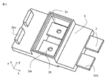
- FIG. 1A and 1B are respectively a perspective view and a partially transparent perspective view of an electrical equipment wiring component according to a first embodiment. BRIEF DESCRIPTION OF THE DRAWINGS It is the perspective view which made a part of electric equipment wiring components concerning Embodiment 1 penetrate.
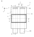
- 1 is a plan view of the electrical equipment wiring component according to the first embodiment;
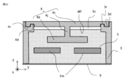
- FIG. 4A and 4B are cross-sectional views of the wiring component for electrical equipment according to the first embodiment, each having a different cross-sectional plane.
- FIG. 10 is a perspective view of an electrical equipment wiring component according to a second embodiment;
- FIG. 2 is a cross-sectional view of an electrical equipment wiring component according to a second embodiment;
- FIG. 11 is a perspective view of a lid member of an electrical equipment wiring component according to a third embodiment
- FIG. 10 is a cross-sectional view of an electrical equipment wiring component according to a third embodiment
- FIG. 11 is a perspective view of a lid member of an electrical equipment wiring component according to a fourth embodiment
- FIG. 11 is a cross-sectional view of an electrical equipment wiring component according to a fourth embodiment
- FIG. 11 is a perspective view of an integrally molded product of a bus bar and a housing of the electrical equipment wiring component according to the fifth embodiment
- FIG. 11 is a perspective view of a lid member of an electrical equipment wiring component according to a sixth embodiment
- FIG. 11 is a cross-sectional view of an electrical equipment wiring component according to a sixth embodiment
- FIG. 10 is a cross-sectional view of an electrical equipment wiring component according to a third embodiment
- FIG. 11 is a perspective view of a lid member of an electrical equipment wiring component according to a fourth embodiment
- FIG. 11 is a cross-section
- FIG. 11 is a perspective view of an integrally molded product of a bus bar and a housing of an electrical equipment wiring component according to a seventh embodiment;
- FIG. 11 is a perspective view of a lid member of an electrical equipment wiring component according to a seventh embodiment;
- FIG. 11 is a cross-sectional view of an electrical equipment wiring component according to a seventh embodiment;
- FIG. 11 is a perspective view of an integrally molded product of a bus bar and a housing of an electrical equipment wiring component according to an eighth embodiment;
- FIG. 21 is a perspective view of a lid member of an electrical equipment wiring component according to an eighth embodiment;
- FIG. 21 is a perspective view of an integrally molded product of a bus bar and a housing of an electrical equipment wiring component according to a ninth embodiment;
- FIG. 21 is a perspective view of a lid member of an electrical equipment wiring component according to a ninth embodiment
- FIG. 21 is a perspective view of an electrical equipment wiring component according to a ninth embodiment
- FIG. 11 is a cross-sectional view of an electrical equipment wiring component according to a ninth embodiment
- Embodiment 1. 1A, 1B to 4A, and 4B are for explaining the configuration of the electrical equipment wiring component according to the first embodiment, and FIG. 1A is a perspective view of the electrical equipment wiring component when viewed from above. 1B is a transparent perspective view showing the state of the lid and busbars from the same viewpoint as in FIG. 1A, and FIG. 1 is a transparent perspective view of a housing portion for illustration; FIG. 3 is a transparent plan view showing the state of the busbar of the electrical equipment wiring component, FIG. 4A is a cross-sectional view corresponding to line AA in FIG. 3, and FIG. 4B is B in FIG. - It is a cross-sectional view corresponding to the B line.
- the basic configuration is that, as shown in FIGS. 1A and 3, both ends (end 2ea, end 2eb) of the bus bar 2 whose intermediate portion is embedded in the housing 3 protrude from the housing 3. .
- it is often used with one end (end 2ea) connected to another device or wiring component that requires airtightness, and the other end (end 2eb) exposed to the outside.
- the intermediate portion 2m of the busbar 2 embedded in the housing 3 by integral molding is covered with the filling material 5 made of elastomer resin all around. configured as Specifically, as shown in FIGS. 1B, 2, and 4B, upper and lower (in the figure z direction) to form a space 3v where the intermediate portion 2m of the bus bar 2 is exposed. Then, as shown in FIG. 4A, an elastic filler 5 formed by curing the potting material filled in the space 3v by potting is configured to cover the entire circumference of the intermediate portion 2m of the bus bar 2. .
- the bus bar 2 is composed of a conductor with excellent electrical conductivity such as copper (Cu) or aluminum (Al), and a total of two bus bars 2A and 2B to which different voltages are applied are spaced apart. It is embedded in the housing 3 by insert molding.
- the housing 3 for example, in addition to thermoplastic resin such as PPS (Poly Phenylene Sulfide), insert molding is possible, and thermosetting resin can be used as long as it is a strong resin as the housing 3. .
- the upper opening (z direction Pour the potting material from the positive side).
- the filling material 5 covering the intermediate portion 2m is formed by hardening the poured potting material.
- the electrical equipment wiring component 1 is completed by covering the other opening with a lid member 4 so that a part (embedding portion 4b) is embedded in the potting material.
- the potting material used for the filler 5 is an elastomer material such as silicone rubber, it does not have the rigidity of the housing, but it is flexible compared to the resin that constitutes the housing 3. , the displacement with the bus bar 2 can be followed. Therefore, at least in the portion covering the bus bar 2, no gap is generated between the bus bar 2 and the bus bar 2. ⁇
- the adhesion between the space 3v and the housing 3 is also good. Therefore, even if the gap between the bus bar 2 and the housing 3 is continuously formed between the end 2ea and the space 3v and between the end 2eb and the space 3v, the gap The space between them is cut off by the filler material 5 . Therefore, even if water enters from the end 2ea to the space 3v, it does not reach the end 2eb, and vice versa.
- the filler 5 is superior to the housing 3 in terms of followability and adhesion, that is, the function of retaining a seal, but is less rigid than the resin material that constitutes the housing 3. If the force is applied, there is a possibility that deformation, chipping, or the like will occur and the sealing performance will be hindered.
- a lid member 4 is provided to block the upper opening of the space portion 3v and prevent external force from being applied to the filler 5. As shown in FIG.
- the lid member 4 is made of a resin having the same rigidity as the housing 3, and is embedded in the filler 5 at the tip of a columnar portion 4j extending from the lid 4c that closes the opening toward the filler 5, A buried portion 4b extending in a direction (y direction) perpendicular to the extending direction (z) is provided.
- the embedded portion 4b exerts an anchor effect in the attachment/detachment direction (z direction) of the lid member 4, thereby preventing the lid member 4 from coming off. It has become.
- the lid member 4 is provided with crushing ribs 4cp at the intermediate portions of the four sides of the lid portion 4c, and has a structure that can be temporarily fixed to the opening of the space portion 3v of the housing 3. As shown in FIG. Therefore, even in a state where the anchoring effect of the lid member 4 is not exhibited before the potting material is cured, the lid member 4 is structured so as not to fall off easily.
- the lid member 4 can be prevented from falling off and the filler 5 from being exposed.
- the opening at the bottom of the space 3v is also closed with a receiving material 9 having the same rigidity as the housing 3 or the lid member 4. good too.
- the receiving member 9 may also be provided with a portion corresponding to the embedded portion 4b that exerts an anchoring effect in the filler 5.
- the receiving material 9 does not necessarily need to exist if the structure is such that external force is not applied to the filler 5 from the lower opening by other members.
- the receiving material 9 may be constructed of, for example, a tape material so that it is used only during the period of filling with the potting material and can be peeled off after the potting material has hardened to form the filling material 5 .
- the space 3v that opens upward and downward is formed at the stage of the integrally molded product.
- integral molding can be performed using only the upper and lower dies without using slide dies, which has the advantage of reducing the cost of the dies.
- Embodiment 2 a configuration will be described that is more excellent in preventing the lid member from coming off than in the case of Embodiment 1 before the potting material is cured as a filling material.
- 5 and 6 are for explaining the configuration of the electrical equipment wiring component according to the second embodiment, FIG. 5 is a perspective view of the electrical equipment wiring component when viewed from above, and FIG. 1 is a cross-sectional view corresponding to line CC of FIG.
- FIG. 4B used in Embodiment 1 is used.
- a concave portion 3a that engages with the snap-fit convex portion 4cf is provided in the upper portion of the outer side surface 3fx surrounding 3v.
- the snap-fit projection 4cf and the recess 3a function as a snap-fit mechanism for forming a snap-fit coupling that restricts movement in the direction of removing the lid member 4 from the housing 3.
- the assembly order is the same as that of the first embodiment. Attach member 4.
- the embedded portion 4b exerts an anchoring effect, and the lid member 4 can be prevented from coming off.
- the difference from the first embodiment is that when the anchor effect is not exhibited, the snap-fit protrusions 4cf and the recesses 3a are temporarily fixed using the snap-fit coupling, so that the ribs 4cp are used to temporarily fix the housing 3 and the housing 3. has a large fixing force.
- this structure is useful when the environment in which the lid member 4 is attached is taken into account and strong temporary fixing is required before the potting material is cured.
- Embodiment 3 the shape of the embedding portion of the cover member is devised with respect to the electrical equipment wiring component according to the first or second embodiment.
- FIGS. 7 and 8 are for explaining the configuration of the electrical equipment wiring component according to the third embodiment, FIG. 7 is a perspective view of the lid member viewed from above, and FIG. 8 corresponds to FIG. 4A. It is a cross-sectional view.
- the same configuration as in the first embodiment or the second embodiment can be applied to the configuration other than the shape of the embedded portion. are omitted, and FIGS. 1A, 1B, 2, and 3 used in Embodiment 1 are used.
- the electrical equipment wiring component 1 according to Embodiment 3 as shown in FIGS. is tilted with respect to More specifically, it has an inclined surface so that the area in the direction perpendicular to the direction extending from the lid portion 4c expands toward the leading end away from the lid portion 4c, and the lid portion 4c extends from the portion where the area has completely expanded. Towards, it was made to have an inclined surface so that an area may narrow.
- the assembly order is the same as that of the first embodiment.
- the lid member 4 is attached before the potting material hardens.
- the filler 5 tends to flow along the slope of the embedded portion 4b, so the possibility of air being caught inside the filler 5 is reduced.
- air bubbles may be connected inside and cause a leak path.
- the embedded part 4b exerts an anchoring effect on the filling material 5 and can prevent the lid member 4 from coming off.
- Embodiment 4 in order to reduce the amount of filler used, the volume of the embedded portion of the cover member is increased in comparison with the electrical equipment wiring components according to the first to third embodiments.
- 9 and 10 are for explaining the configuration of the electrical equipment wiring component according to the fourth embodiment, FIG. 9 is a perspective view of the lid member as seen from above, and FIG. 10 corresponds to FIG. 4A. It is a cross-sectional view.
- the same configuration as in the first to third embodiments can be applied except for the shape of the embedded portion, and the description of the same parts will be omitted.
- the volume of the embedded portion 4b of the lid member 4 is increased compared to the embedded portions 4b of the first to third embodiments. , and is indistinguishable from the columnar portion 4j.
- the assembly order is the same as that of the first embodiment. Attach member 4.
- the fourth embodiment has a structure in which the volume of the portion of the cover member 4 inserted into the filling material 5 (the buried portion 4b including the portion corresponding to the columnar portion 4j in the first embodiment) is increased.
- the amount of filling material 5 is reduced, but the amount of filling material 5 is sufficient to satisfy the waterproof function for the purpose of filling the filling material 5 and the insulation performance between bus bars of different voltages.
- the filling volume can be reduced. Therefore, it is possible to increase the volume of the embedded portion 4b and reduce the filling amount of the filler 5 until the above filling amount is achieved.
- the potting material that constitutes the filler 5 is more expensive than the resin material that constitutes the housing 3 and the like. become.
- FIG. 11 is for explaining the configuration of the electrical equipment wiring component according to the fifth embodiment, and is a perspective view of an integrally molded product of a bus bar and a housing as viewed from above.
- FIG. 4A and FIG. 4B used in Embodiment 1 are referred to for the relationship between the embedded portion and the filler.
- the surface facing the opening of the intermediate portion 2m to be covered with the filler 5 of the bus bar 2 is penetrated in the vertical direction (z).
- a through hole 2h is provided.
- the assembly order is the same as that of the first embodiment. Attach member 4.
- the filling material 5 should be filled in the space 3v without inclusion of air bubbles, so the filling takes a sufficient amount of time. However, it is difficult to completely eliminate air bubbles generated inside the filling material 5 only by injecting the potting material in the air. Therefore, in the fifth embodiment, the intermediate portion 2m of the bus bar 2 exposed in the space 3v is provided with a through hole 2h penetrating in the vertical direction.
- the potting material When the potting material is injected into the integrally molded product in which the receiving material 9 is attached to the bottom of the space 3v, the potting material gradually fills from the bottom of the space 3v and tends to accumulate on the lower surface of the bus bar 2. Air bubbles can escape from the through holes 2h. Therefore, the structure is such that air bubbles are less likely to accumulate inside the filling material 5 formed by curing the potting material. Further, the through holes 2h can be used for positioning the busbars 2 during insert molding, and the through holes 2h of the busbars 2 are not exposed to the outside after the potting material is filled.
- the positioning of the busbars is important. exposed to the outside. If used in such a state, conductive substances such as salt may accumulate on the electrical equipment wiring components, causing a short circuit within the electrical equipment wiring components. Therefore, a step of filling the exposed portion with an adhesive may be required.
- the portion exposed from the housing 3 in which the through hole 2h is formed is covered with the filler 5. The through holes 2h to be used are not exposed. Therefore, there is an advantage that an additional adhesive application process becomes unnecessary.
- the same configuration as in the first to fifth embodiments can be applied to the configuration other than the cover plate of the lid member, and the description of the same parts will be omitted.
- 1A, 1B, 2, and 3 used in Embodiment 1 are also used.
- the upper surface portion of the filler 5 is placed between the embedded portion 4b and the lid portion 4c of the columnar portion 4j of the lid member 4.
- a cover plate 4t is provided to cover the .
- Embodiment 7 a structure is described in which a labyrinth structure is formed between the cover member and the housing in order to strengthen the isolation between the filler and the outside.
- 14 to 16 are for explaining the configuration of the electrical equipment wiring component according to the seventh embodiment, and FIG. 14 is a perspective view and a diagram of the integrally molded product of the bus bar and the housing as viewed from above. 15 is a perspective view of the lid member as seen from below, and FIG. 16 is a sectional view corresponding to FIG. 4A.
- the same configuration as in the first to sixth embodiments can be applied to the configuration other than the labyrinth structure between the lid member and the housing. Description is omitted, and FIGS. 1A, 1B, 2, and 3 used in Embodiment 1 are used.
- a groove 3d recessed in the z direction is formed along the entire circumference at the inner edge of the upper opening of the space 3v in the housing 3,
- a ridge portion 3r protruding in the z-direction is formed along the entire circumference inside the groove portion 3d in the xy plane.
- the cover member 4 is provided with ridges 4r corresponding to the grooves 3d on the outer edge of the surface 4ff of the cover 4c facing the space 3v.
- a groove portion 4d corresponding to the ridge portion 3r is formed inside the portion 4r over the entire circumference.
- the ridges 3r are fitted into the grooves 4d, and the ridges 4r are fitted into the grooves 3d, as shown in FIG. 16, forming a labyrinth seal structure.
- the space 3v can be isolated from the outside. That is, the groove portion 4d, the ridge portion 3r, the groove portion 3d, and the ridge portion 4r are combined to function as a labyrinth seal mechanism.
- the labyrinth seal structure it is possible to prevent liquids such as salt water and water from entering through the gap between the lid member 4 and the housing 3 when the electrical equipment wiring component 1 is installed outside.
- Embodiment 8 In the eighth embodiment, a configuration in which the lid member and the housing are fixed by a screw structure will be described. 17 and 18 are for explaining the configuration of the electrical equipment wiring component according to Embodiment 8, and FIG. 18 is a perspective view when the lid member is viewed from below.
- the same configuration as in the first and third to seventh embodiments can be applied to the configuration other than the structure for fixing the lid member and the housing, and the same parts 4A and 4B used in the first embodiment are referred to for the relationship between the bus bar, the embedded portion, and the filler.
- the opening portion of the space 3v of the housing 3 is formed into a cylindrical shape having a circular shape in the xy plane, and the upper opening A female screw 3fs was formed on the inner peripheral surface of the.
- the lid member 4 also has a circular lid portion 4c and a male screw 4 cms corresponding to the female screw 3 fs is formed on the outer peripheral surface.
- the cover member 4 when the cover member 4 is put on the housing 3, it is inserted while being rotated along the screw, and is fixed by the screw structure. Powerful.
- the attached state of the lid member 4 is easier to visually recognize than the temporarily fixed state with the ribs 4cp. For example, if the direction of the load applied to the lid member 4 is tilted from the vertical direction (z direction) during temporary fixing by the ribs 4cp, the ribs 4cp are not crushed and the expected fixing force is not exerted. It is conceivable that the member 4 is attached.
- the lid member 4 is positioned at a specified height with respect to the housing 3, and there is a possibility that the lid member 4 is mistakenly attached.
- the fixing method of the cover member 4 having a screw structure is easy to install, and the above concerns can be dispelled. Further, in the case of the screw structure, the lid member 4 can be removed, and even if the attachment of the lid member 4 fails, it can be repeatedly attached and detached before the potting material hardens.
- Embodiment 9 In each of the above-described embodiments, an example in which a space is provided to collectively expose the intermediate portions of a plurality of busbars has been described. In the ninth embodiment, an example will be described in which a plurality of spaces partitioned by partition walls are provided to expose intermediate portions of individual bus bars.
- 19 to 22 are for explaining the configuration of the electrical equipment wiring component according to the ninth embodiment, and FIG. 19 is a perspective view and a diagram of an integrally molded product of a bus bar and a housing as viewed from above. 20 is a perspective view of the lid member as seen from below, and FIG. 21 is a perspective view of the electrical equipment wiring component as seen from above. 22 is a cross-sectional view corresponding to line DD of FIG.
- the same configuration as in the first to eighth embodiments can be applied except that the space portions are individually provided corresponding to the individual busbars. The description of these parts is omitted.
- the intermediate portions 2m of the busbars 2A and 2B are partitioned by the partition wall 3p, and the space portions 3vA and 3vB are provided to individually expose the busbars 2A and 2B. bottom.
- the lid member 4 extends to the lid portion 4c that collectively closes the two space portions 3vA and 3vB, extends with respect to each of the space portions 3vA and 3vB, and embeds portions 4bA and 4bB at the respective ends. is provided with columnar portions 4jA and 4jB.
- the assembly order is the same as in the above embodiments, and after the busbars 2 are insert-molded using the resin forming the housing 3 , the receiving material 9 is attached to the housing 3 .
- the potting material to be the filling material 5 (filling materials 5A and 5B) is potted separately for each of the space portions 3vA and 3vB. After the potting material is injected into each of the spaces 3vA and 3vB, the lid member 4 is attached before the filling material 5 is hardened.
- the embedded parts 4bA and 4bB are anchored in the attachment/detachment direction (z direction) of the lid member 4, respectively, as shown in FIGS. It has a structure that exhibits an effect and prevents the lid member 4 from coming off. Moreover, since the partition wall 3p can secure the spatial distance and creepage distance between the busbars 2A and 2B in advance, even if the filling condition of the filler 5 varies, the insulation between the two can be securely secured.
- the present invention is not limited to this.
- one lid portion 4c may be provided with one space portion 3v.
- the present invention is not limited to this, and the lid member 4 may be provided for each of the spaces 3v.
- thermosetting elastomers or thermoplastic elastomers may be used as long as they satisfy adhesion and followability, and any material called elastic polymer can be used. is.
- the material constituting the housing 3 is not limited to thermoplastic resin, and thermosetting resin may be used as long as the bus bar 2 is embedded and the material has rigidity as a housing.
- the space portion 3v is shown as an example in which the space portion 3v is opened vertically so that molding can be performed only by the upper and lower dies, but the space portion 3v is not limited to this.
- the bus bars 2 may be made of any conductor having excellent conductivity, and the number of bus bars is not limited to two.
- the plurality of busbars 2 and both ends (ends 2ea, 2eb) of each of the plurality of busbars 2 are exposed, and are spaced apart from each other.
- the housing 3 is made of a resin and has a space 3v formed with openings through which the intermediate portions 2m of the plurality of bus bars 2 are exposed.
- a filling material 5 made of elastomer covering the entire circumference of the bus bar 2 at the boundary between and a lid portion 4c that closes the opening and extends toward the filling material 5 from the lid portion 4c and is embedded in the filling material 5 It is configured to include a lid member 4 having an embedded portion 4b.
- the space 3v is configured to have a second opening on the opposite side of the opening closed by the lid 4c, it becomes possible to perform molding using upper and lower molds without using slide molds.
- the housing 3 is integrally molded with a plurality of busbars 2, it can be manufactured easily, and in particular, when it has a second opening, it can be manufactured more easily using only upper and lower dies.
- the embedded portion 4b has a portion whose area in the direction (xy plane direction) perpendicular to the direction (z direction) extending from the lid portion 4c increases toward the distal end away from the lid portion 4c.
- the filling material 5 is configured so as to cover the entire circumference of the intermediate portion 2m, even if a plurality of busbars 2 are arranged without partitions in the space portion 3v, leakage current between the busbars 2 can be reliably suppressed. can be prevented.
- a ridge 4r projecting in the thickness direction and a groove 4d recessed in the thickness direction are formed along the entire circumference of the outer edge of the face 4ff facing the opening of the lid 4c.
- the lid member 4 and the housing 3 are provided with a snap-fit mechanism for forming a snap-fit coupling that regulates movement in the direction of removing the lid member 4 from the housing 3 when the lid portion 4c closes the opening. With this configuration, it is possible to prevent the lid member 4 from falling off from the housing 3 even before the potting material hardens.
- a male screw 4 cms is formed on the outer peripheral surface of the lid portion 4c, and a female screw 3 fs corresponding to the male screw 4 cms is formed on the inner peripheral surface of the opening of the housing 3. It is possible to prevent the lid member 4 from falling off from the housing 3 even before the potting material hardens.
Landscapes
- Engineering & Computer Science (AREA)
- Microelectronics & Electronic Packaging (AREA)
- Manufacturing & Machinery (AREA)
- Casings For Electric Apparatus (AREA)
- Structure Of Printed Boards (AREA)
- Connection Or Junction Boxes (AREA)
Priority Applications (5)
| Application Number | Priority Date | Filing Date | Title |
|---|---|---|---|
| JP2023537777A JP7511769B2 (ja) | 2021-07-27 | 2021-07-27 | 電気機器配線部品 |
| DE112021008024.5T DE112021008024B4 (de) | 2021-07-27 | 2021-07-27 | Verdrahtungskomponente für elektrische geräte |
| US18/570,147 US12609517B2 (en) | 2021-07-27 | 2021-07-27 | Wiring component for electrical equipment |
| PCT/JP2021/027658 WO2023007571A1 (ja) | 2021-07-27 | 2021-07-27 | 電気機器配線部品 |
| CN202180100606.0A CN117694023A (zh) | 2021-07-27 | 2021-07-27 | 电气设备配线部件 |
Applications Claiming Priority (1)
| Application Number | Priority Date | Filing Date | Title |
|---|---|---|---|
| PCT/JP2021/027658 WO2023007571A1 (ja) | 2021-07-27 | 2021-07-27 | 電気機器配線部品 |
Publications (1)
| Publication Number | Publication Date |
|---|---|
| WO2023007571A1 true WO2023007571A1 (ja) | 2023-02-02 |
Family
ID=85086440
Family Applications (1)
| Application Number | Title | Priority Date | Filing Date |
|---|---|---|---|
| PCT/JP2021/027658 Ceased WO2023007571A1 (ja) | 2021-07-27 | 2021-07-27 | 電気機器配線部品 |
Country Status (5)
| Country | Link |
|---|---|
| US (1) | US12609517B2 (https=) |
| JP (1) | JP7511769B2 (https=) |
| CN (1) | CN117694023A (https=) |
| DE (1) | DE112021008024B4 (https=) |
| WO (1) | WO2023007571A1 (https=) |
Citations (3)
| Publication number | Priority date | Publication date | Assignee | Title |
|---|---|---|---|---|
| JPH01166417U (https=) * | 1988-05-10 | 1989-11-21 | ||
| JP2004084279A (ja) * | 2002-08-27 | 2004-03-18 | Bridgestone Corp | 天井点検口の蓋体固定構造 |
| JP2013027053A (ja) * | 2011-07-14 | 2013-02-04 | Auto Network Gijutsu Kenkyusho:Kk | 半導体モジュール、及び、電気接続箱 |
Family Cites Families (8)
| Publication number | Priority date | Publication date | Assignee | Title |
|---|---|---|---|---|
| JP2002027636A (ja) | 2000-07-04 | 2002-01-25 | Sumitomo Wiring Syst Ltd | 高電圧用電気接続箱に用いる回路体 |
| JP3698034B2 (ja) | 2000-08-25 | 2005-09-21 | 住友電装株式会社 | ジャンクションボックス |
| US6333463B1 (en) * | 2000-11-17 | 2001-12-25 | Tyco Electronics Corporation | Wire separators having sealant material reservoirs and cable splice closures employing such separators |
| JP2006074907A (ja) | 2004-09-02 | 2006-03-16 | Honda Motor Co Ltd | 電源分配装置 |
| JP2011193566A (ja) | 2010-03-12 | 2011-09-29 | Nissin Kogyo Co Ltd | 電子基板の電気接続構造 |
| JP6194868B2 (ja) | 2014-09-18 | 2017-09-13 | 株式会社オートネットワーク技術研究所 | 電気接続箱 |
| DE102017204949B4 (de) * | 2017-03-23 | 2024-11-28 | SUMIDA Components & Modules GmbH | Induktives Bauelement und Verfahren zum Herstellen eines induktiven Bauelements |
| JP7415742B2 (ja) * | 2020-03-31 | 2024-01-17 | 株式会社デンソー | 電力変換装置 |
-
2021
- 2021-07-27 DE DE112021008024.5T patent/DE112021008024B4/de active Active
- 2021-07-27 US US18/570,147 patent/US12609517B2/en active Active
- 2021-07-27 JP JP2023537777A patent/JP7511769B2/ja active Active
- 2021-07-27 CN CN202180100606.0A patent/CN117694023A/zh active Pending
- 2021-07-27 WO PCT/JP2021/027658 patent/WO2023007571A1/ja not_active Ceased
Patent Citations (3)
| Publication number | Priority date | Publication date | Assignee | Title |
|---|---|---|---|---|
| JPH01166417U (https=) * | 1988-05-10 | 1989-11-21 | ||
| JP2004084279A (ja) * | 2002-08-27 | 2004-03-18 | Bridgestone Corp | 天井点検口の蓋体固定構造 |
| JP2013027053A (ja) * | 2011-07-14 | 2013-02-04 | Auto Network Gijutsu Kenkyusho:Kk | 半導体モジュール、及び、電気接続箱 |
Also Published As
| Publication number | Publication date |
|---|---|
| DE112021008024B4 (de) | 2025-11-06 |
| DE112021008024T5 (de) | 2024-05-16 |
| US12609517B2 (en) | 2026-04-21 |
| CN117694023A (zh) | 2024-03-12 |
| JPWO2023007571A1 (https=) | 2023-02-02 |
| US20240275153A1 (en) | 2024-08-15 |
| JP7511769B2 (ja) | 2024-07-05 |
Similar Documents
| Publication | Publication Date | Title |
|---|---|---|
| JP4680231B2 (ja) | コネクタ | |
| EP2451019B1 (en) | Method for integrally forming connector, and connector | |
| CN107851926A (zh) | 电缆组件 | |
| JP5242112B2 (ja) | フレキシブルフラットハーネス及びその製造方法並びにスライドドアの給電装置 | |
| CN101855732A (zh) | 用于光电太阳能板的接线盒 | |
| CN112997365A (zh) | 电导体与电气设备连接件电接触的接触元件及其制造方法 | |
| JP5939177B2 (ja) | ワイヤハーネス | |
| JP5932553B2 (ja) | コネクタおよびコネクタの成形方法 | |
| US10199984B2 (en) | Housing for solar panel electric connection | |
| CN113169469B (zh) | 电缆接头、接触元件及其制造方法 | |
| JP5591374B1 (ja) | 防水型主端子 | |
| EP3726552A1 (en) | A sealed electric switch asembly | |
| KR20110124765A (ko) | 체결 장치를 구비한 전기 모듈 | |
| JP6328684B2 (ja) | 電動機の防水構造 | |
| WO2023007571A1 (ja) | 電気機器配線部品 | |
| US5057030A (en) | Grommet/seal member for a connector assembly | |
| US20080149364A1 (en) | Ribbon cable | |
| CN110603693B (zh) | 电子模块和制造方法 | |
| KR20200143939A (ko) | 배터리 팩 | |
| JP6013802B2 (ja) | コネクタの成形方法 | |
| US20210195758A1 (en) | Resin-sealed in-vehicle electronic control device | |
| JP6813597B2 (ja) | センサ装置及びセンサ装置の製造方法 | |
| EP2565988B1 (en) | Sealing arrangement | |
| WO2018097175A1 (ja) | 水中モータ及び防水コネクタ | |
| EP4336686A1 (en) | Gas-insulated switchgear |
Legal Events
| Date | Code | Title | Description |
|---|---|---|---|
| 121 | Ep: the epo has been informed by wipo that ep was designated in this application |
Ref document number: 21951782 Country of ref document: EP Kind code of ref document: A1 |
|
| ENP | Entry into the national phase |
Ref document number: 2023537777 Country of ref document: JP Kind code of ref document: A |
|
| WWE | Wipo information: entry into national phase |
Ref document number: 18570147 Country of ref document: US |
|
| WWE | Wipo information: entry into national phase |
Ref document number: 202180100606.0 Country of ref document: CN |
|
| WWE | Wipo information: entry into national phase |
Ref document number: 112021008024 Country of ref document: DE |
|
| 122 | Ep: pct application non-entry in european phase |
Ref document number: 21951782 Country of ref document: EP Kind code of ref document: A1 |
|
| WWG | Wipo information: grant in national office |
Ref document number: 112021008024 Country of ref document: DE |