WO2022264955A1 - 端子金具及び連鎖端子 - Google Patents
端子金具及び連鎖端子 Download PDFInfo
- Publication number
- WO2022264955A1 WO2022264955A1 PCT/JP2022/023570 JP2022023570W WO2022264955A1 WO 2022264955 A1 WO2022264955 A1 WO 2022264955A1 JP 2022023570 W JP2022023570 W JP 2022023570W WO 2022264955 A1 WO2022264955 A1 WO 2022264955A1
- Authority
- WO
- WIPO (PCT)
- Prior art keywords
- terminal
- box
- insertion direction
- terminal fitting
- contact
- Prior art date
- Legal status (The legal status is an assumption and is not a legal conclusion. Google has not performed a legal analysis and makes no representation as to the accuracy of the status listed.)
- Ceased
Links
Images






Classifications
-
- H—ELECTRICITY
- H01—ELECTRIC ELEMENTS
- H01R—ELECTRICALLY-CONDUCTIVE CONNECTIONS; STRUCTURAL ASSOCIATIONS OF A PLURALITY OF MUTUALLY-INSULATED ELECTRICAL CONNECTING ELEMENTS; COUPLING DEVICES; CURRENT COLLECTORS
- H01R13/00—Details of coupling devices of the kinds covered by groups H01R12/70 or H01R24/00 - H01R33/00
- H01R13/02—Contact members
- H01R13/22—Contacts for co-operating by abutting
- H01R13/24—Contacts for co-operating by abutting resilient; resiliently-mounted
- H01R13/2407—Contacts for co-operating by abutting resilient; resiliently-mounted characterized by the resilient means
- H01R13/2428—Contacts for co-operating by abutting resilient; resiliently-mounted characterized by the resilient means using meander springs
-
- H—ELECTRICITY
- H01—ELECTRIC ELEMENTS
- H01R—ELECTRICALLY-CONDUCTIVE CONNECTIONS; STRUCTURAL ASSOCIATIONS OF A PLURALITY OF MUTUALLY-INSULATED ELECTRICAL CONNECTING ELEMENTS; COUPLING DEVICES; CURRENT COLLECTORS
- H01R13/00—Details of coupling devices of the kinds covered by groups H01R12/70 or H01R24/00 - H01R33/00
- H01R13/40—Securing contact members in or to a base or case; Insulating of contact members
- H01R13/42—Securing in a demountable manner
- H01R13/422—Securing in resilient one-piece base or case, e.g. by friction; One-piece base or case formed with resilient locking means
-
- H—ELECTRICITY
- H01—ELECTRIC ELEMENTS
- H01R—ELECTRICALLY-CONDUCTIVE CONNECTIONS; STRUCTURAL ASSOCIATIONS OF A PLURALITY OF MUTUALLY-INSULATED ELECTRICAL CONNECTING ELEMENTS; COUPLING DEVICES; CURRENT COLLECTORS
- H01R13/00—Details of coupling devices of the kinds covered by groups H01R12/70 or H01R24/00 - H01R33/00
- H01R13/02—Contact members
- H01R13/15—Pins, blades or sockets having separate spring member for producing or increasing contact pressure
- H01R13/187—Pins, blades or sockets having separate spring member for producing or increasing contact pressure with spring member in the socket
-
- H—ELECTRICITY
- H01—ELECTRIC ELEMENTS
- H01R—ELECTRICALLY-CONDUCTIVE CONNECTIONS; STRUCTURAL ASSOCIATIONS OF A PLURALITY OF MUTUALLY-INSULATED ELECTRICAL CONNECTING ELEMENTS; COUPLING DEVICES; CURRENT COLLECTORS
- H01R2103/00—Two poles
-
- H—ELECTRICITY
- H01—ELECTRIC ELEMENTS
- H01R—ELECTRICALLY-CONDUCTIVE CONNECTIONS; STRUCTURAL ASSOCIATIONS OF A PLURALITY OF MUTUALLY-INSULATED ELECTRICAL CONNECTING ELEMENTS; COUPLING DEVICES; CURRENT COLLECTORS
- H01R4/00—Electrically-conductive connections between two or more conductive members in direct contact, i.e. touching one another; Means for effecting or maintaining such contact; Electrically-conductive connections having two or more spaced connecting locations for conductors and using contact members penetrating insulation
- H01R4/10—Electrically-conductive connections between two or more conductive members in direct contact, i.e. touching one another; Means for effecting or maintaining such contact; Electrically-conductive connections having two or more spaced connecting locations for conductors and using contact members penetrating insulation effected solely by twisting, wrapping, bending, crimping, or other permanent deformation
- H01R4/18—Electrically-conductive connections between two or more conductive members in direct contact, i.e. touching one another; Means for effecting or maintaining such contact; Electrically-conductive connections having two or more spaced connecting locations for conductors and using contact members penetrating insulation effected solely by twisting, wrapping, bending, crimping, or other permanent deformation by crimping
- H01R4/183—Electrically-conductive connections between two or more conductive members in direct contact, i.e. touching one another; Means for effecting or maintaining such contact; Electrically-conductive connections having two or more spaced connecting locations for conductors and using contact members penetrating insulation effected solely by twisting, wrapping, bending, crimping, or other permanent deformation by crimping for cylindrical elongated bodies, e.g. cables having circular cross-section
- H01R4/184—Electrically-conductive connections between two or more conductive members in direct contact, i.e. touching one another; Means for effecting or maintaining such contact; Electrically-conductive connections having two or more spaced connecting locations for conductors and using contact members penetrating insulation effected solely by twisting, wrapping, bending, crimping, or other permanent deformation by crimping for cylindrical elongated bodies, e.g. cables having circular cross-section comprising a U-shaped wire-receiving portion
- H01R4/185—Electrically-conductive connections between two or more conductive members in direct contact, i.e. touching one another; Means for effecting or maintaining such contact; Electrically-conductive connections having two or more spaced connecting locations for conductors and using contact members penetrating insulation effected solely by twisting, wrapping, bending, crimping, or other permanent deformation by crimping for cylindrical elongated bodies, e.g. cables having circular cross-section comprising a U-shaped wire-receiving portion combined with a U-shaped insulation-receiving portion
Definitions
- the present disclosure relates to terminal fittings and chain terminals.
- Patent Document 1 discloses a first abutting terminal fitting having a projecting butting surface and a second abutting terminal fitting in which a plurality of leaf spring pieces are alternately arranged on the same plane. , is disclosed.
- the leaf spring piece when the abutment surface abuts against the leaf spring piece, the leaf spring piece is elastically deformed, thereby generating a predetermined contact pressure between the abutment surface and the leaf spring piece to establish electrical connection.
- Patent Document 1 one leaf spring extends in a cantilever shape, so the amount of displacement of the leaf spring in the fitting direction is small. Therefore, if the dimensions of each part vary in the fitting direction (that is, the direction in which the abutment surface abuts the leaf spring piece), there is a concern that the abutment surface and the leaf spring piece may not be electrically connected.
- the terminal fitting and the chain terminal of the present disclosure have been completed based on the above circumstances, and an object thereof is to provide a terminal fitting and a chain terminal that can maintain connection reliability with a mating terminal.
- the terminal fitting disclosed in the first disclosure is a box portion into which the mating terminal is inserted from the front; a base secured within the box; a contact portion disposed in front of the base portion and electrically contacting a mating terminal inserted into the box portion; a spring portion provided to connect the base portion and the contact portion and supporting the contact portion so as to be displaceable in an insertion direction of the mating terminal;
- a terminal fitting comprising The spring portion has a shape in which a plurality of plate portions elongated in a direction intersecting the insertion direction are folded back at intervals in the insertion direction.
- the chain terminal of the second disclosure includes: A chain terminal in which a plurality of terminal fittings disclosed in the first disclosure are arranged in parallel and protrude from one carrier, The terminal fitting has a crimping portion protruding from the box portion, In the unfolded state before bending the terminal fitting, the spring portion and the crimping portion are arranged between the box portion and the carrier.
- connection reliability with the mating terminal can be maintained.
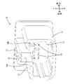
- FIG. 1 is a perspective view of a female housing into which terminal fittings are inserted.
- FIG. 2 is a perspective view of the male housing into which the mating terminal is inserted.
- FIG. 3 is a cross-sectional view taken along line AA in FIG.
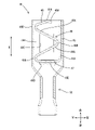
- FIG. 4 is a perspective view of a terminal fitting.
- 5 is a cross-sectional view taken along the line BB in FIG. 4.
- FIG. 6 is a plan view of the chain terminal.
- FIG. 7 is a plan view of the chain terminal with the terminal fittings in an unfolded state.
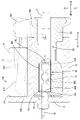
- FIG. 8 is a side sectional view showing the process of fitting the female housing and the male housing together.
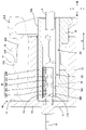
- FIG. 9 is a side cross-sectional view showing a state in which fitting between the female housing and the male housing is completed.
- FIG. 10 corresponds to a cross-sectional view taken along the line BB in FIG. 4 and shows a change in attitude of the contact portion before and after being pressed by the mating terminal.
- the terminal fitting of the present disclosure is (1) A box portion, a base portion, a contact portion, and a spring portion are provided.
- the mating terminal is inserted into the box portion from the front.
- the base portion is secured within the box portion.
- the contact portion is arranged in front of the base portion and electrically contacts the mating terminal inserted into the box portion.
- the spring portion is provided so as to connect the base portion and the contact portion, and supports the contact portion so as to be displaceable in the insertion direction of the mating terminal.
- the spring part has a shape in which a plurality of plate parts elongated in a direction intersecting the insertion direction are folded back at intervals in the insertion direction.
- the plurality of plate portions constituting the spring portion are arranged at intervals in the insertion direction, when the contact portion is pressed in the insertion direction by the mating terminal, the contact portion is pushed in the insertion direction. It is possible to ensure a large amount of displacement to. As a result, even if the dimensions of each component vary, the reliability of connection with the mating terminal can be maintained.
- the plate portions, the plate portion and the base portion, and the plate portion and the contact portion that are adjacent to each other in the insertion direction are connected by bent-shaped connecting portions, and the number of connecting portions is an odd number. is preferably provided. According to this configuration, since the number of plate portions is even, the orientation of the contact portion is less likely to be biased.
- the plate portion of the terminal fitting according to the present disclosure is formed so that the width becomes narrower as the distance from the connecting portion increases. According to this configuration, when the contact portion is pressed in the insertion direction by the mating terminal, the load applied to each connecting portion can be distributed to the plate portion, so fatigue of the connecting portion can be reduced.
- a chain terminal in which a plurality of terminal fittings described in (1) to (3) above are arranged in parallel and protrude from one carrier, wherein the terminal fitting is crimped and protrudes from the box portion. has a part.
- the spring portion and the crimping portion are arranged between the box portion and the carrier. According to this configuration, the material between the box portion and the carrier can be effectively utilized as compared with the case where the spring portion and the box portion are arranged along the carrier.
- FIG. 1 A first embodiment embodying the present disclosure will be described with reference to FIGS. 1 to 10.
- FIG. 1 regarding the front-rear direction, the downward direction in FIG. 3 is defined as the forward direction, and the upward direction is defined as the rearward direction.
- the front side of FIG. 3 is defined as the upper side, and the rear side is defined as the lower side.
- left and right directions the left side of FIG. 3 is defined as the right side, and the right side is defined as the left side.
- the terminal fitting 45 of the present disclosure is in electrical contact with the mating terminal 18 . As shown in FIG. 1, the terminal fitting 45 is attached to the female housing 30 . As shown in FIG. 2 , the mating terminal 18 is attached to the male housing 10 .
- the male housing 10 is made of synthetic resin.
- the male housing 10 has a block shape as a whole.
- the male housing 10 has a wall-shaped terminal holding portion 11 through which the mating terminals 18 pass, and a rectangular tubular receptacle 12 protruding from the outer peripheral edge of the terminal holding portion 11 toward the female housing 30 . .
- the upper wall portion 13 of the hood portion 12 is formed with a first relief recess portion 14A and a second relief recess portion 14B formed by recessing the inner surface (lower surface) of the upper wall portion 13 upward.
- the first escape recess 14A is arranged in the center in the left-right direction and extends in the front-rear direction from the front end (open end) of the hood portion 12 to the rear end.
- the second escape recess 14B is arranged on the right side in the left-right direction and extends in the front-rear direction from the front end (open end) of the receptacle 12 to the back end.
- a hole 15 penetrating through the upper wall portion 13 is formed in a region of the upper wall portion 13 where the first relief recess portion 14A is formed.
- the hole 15 is arranged at a position slightly deeper than the tip (open end) of the receptacle 12 .
- a locking engagement portion 16 is formed at the opening edge (tip) of the receptacle 12 on the tip side of the hole 15 .
- a surface of the locking engaging portion 16 facing the hole 15 is formed as an engaging surface 17 (see FIGS. 8 and 9).
- the lock engaging portion 16 is arranged in front of the hole 15 (on the opening end side of the hood portion 12) so as to be adjacent to it.
- the mating terminal 18 is made of an elongated strip of metal. One end of the mating terminal 18 extends to be exposed to the outside of the terminal holding portion 11, as shown in FIGS. The other end of the mating terminal 18 protrudes from the terminal holding portion 11 into the receptacle 12 and is formed by folding the other end toward the one end. A contact surface 18 ⁇ /b>A that curves toward the open end of the receptacle 12 is formed at the other end of the mating terminal 18 . A bead portion 48B of the contact portion 48 of the terminal fitting 45 electrically contacts the contact surface 18A.
- the female housing 30 is made of synthetic resin.
- the female housing 30 has a block shape as a whole.
- a plurality of terminal receiving chambers 31 are formed in the female housing 30 so as to pass through the female housing 30 in the front-rear direction.
- the plurality of terminal accommodating chambers 31 are arranged in alignment in the left-right direction.
- An elastically deformable lance 32 is formed at the front end of the terminal receiving chamber 31 .
- the female housing 30 has a housing space 33.
- the accommodation space 33 opens to the lower surface of the female housing 30 .
- the accommodation space 33 communicates with all the terminal accommodation chambers 31 .
- the housing space 33 is arranged in the central portion of the female housing 30 (position behind the lance 32) in the front-rear direction.
- a retainer (not shown) is fitted in the accommodation space 33 to prevent the terminal fitting 45 inserted into the female housing 30 (terminal accommodation chamber 31 ) from coming off.
- the upper wall 30S of the female housing 30 is provided with a pair of projections 41 projecting upward, a projection 42 projecting upward, and a lock portion 43.
- the pair of protrusions 41 are arranged at the rear end of the female housing 30 and are bilaterally symmetrical.
- the projecting portion 42 is arranged at the front end portion on the right side of the female housing 30 .
- the locking portion 43 has a base portion 43A, an arm portion 43B, a locking piece 43C, and an operating portion 43D.
- the base portion 43A rises upward from the front end portion of the upper wall 30S of the female housing 30.
- the arm portion 43B extends rearward in a cantilevered manner from the tip of the base portion 43A.
- 43 C of locking pieces are provided in the front-back direction center part of the arm part 43B so that it may protrude upward.
- the front side of the engaging piece 43C is formed as an inclined surface 43E that inclines rearward and upward, and the rear end is formed as an engaging surface 43F that is steeply formed in the vertical direction.
- the operation part 43D is provided at the tip of the arm part 43B so as to protrude upward.
- a die-cutting hole 43G which is formed when the locking surface 43F is molded, opens in the operation portion 43D.
- the tip (rear end) of the arm portion 43B and the operation portion 43D are arranged between the pair of protrusions 41 .
- the terminal fitting 45 is a single member formed by bending a metal plate, and has an elongated shape in the front-rear direction as a whole. As shown in FIGS. 4 and 5, the terminal fitting 45 includes a box portion 46 , a base portion 47 , a contact portion 48 , a spring portion 49 and a crimping portion 50 .
- the box part 46 has a rectangular tubular shape with open front and rear ends.
- the mating terminal 18 is inserted into the box portion 46 from the front (see FIG. 9).
- the base portion 47 has its proximal end fixed to the rear end portion of the right wall 46A of the box portion 46 and extends leftward so as to block the rear end portion of the box portion 46 . That is, the base portion 47 is fixed inside the box portion 46 .
- a bottom wall 46B of the box portion 46 is formed with a locked hole 46C penetrating in the plate thickness direction (see FIG. 5).
- a through hole 46D passing through in the plate thickness direction is formed in the lower wall 46B behind the locked hole 46C (see FIG. 5).
- a supporting portion 46E is provided adjacently to the rear of the base portion 47 (see FIG. 5).
- the support portion 46E has a base end fixed to the rear end portion of the upper wall 46F of the box portion 46 and extends downward so as to block the rear end portion of the box portion 46 (see FIG. 8).
- a tip portion of the support portion 46E is inserted through the through hole 46D (see FIG. 8).
- the contact portion 48 is provided inside the box portion 46 so as to close the front end portion of the box portion 46 .
- the contact portion 48 is arranged inside the box portion 46 ahead of the base portion 47 .
- the contact portion 48 extends in a direction intersecting the front-rear direction and the left-right direction, and has a rearward bending portion 48A at the front end portion.
- a bead portion 48B is formed at the proximal end portion of the bent portion 48A so as to bulge forward.
- the bead portion 48B of the contact portion 48 electrically contacts the contact surface 18A of the mating terminal 18 inserted into the box portion 46 (see FIGS. 8 and 9).
- the bead portion 48B is arranged along the front end of the box portion 46 before the mating terminal 18 is inserted into the box portion 46 (see FIGS. 5, 8 and 10).
- the spring portion 49 is provided so as to connect the base portion 47 and the contact portion 48 .
- the base portion 47, the contact portion 48, and the spring portion 49 form a belt-like shape elongated in one direction in an unfolded state before being bent (see FIG. 7).
- the spring portion 49 has a plurality of plate portions 49A and a plurality of connecting portions 49B.
- the plurality of plate portions 49A are elongated in a direction intersecting the insertion direction R. As shown in FIG. These plate portions 49A are arranged so as to be folded back in the left-right direction at intervals in the insertion direction R. As shown in FIG.
- Each plate portion 49A extends in a direction intersecting the front-rear direction and the left-right direction.
- the width of each plate portion 49A in the lateral direction is formed so as to narrow from both ends in the longitudinal direction toward the center (see FIG. 7).
- each connecting portion 49B connects the plate portions 49A adjacent in the front-rear direction, the plate portion 49A and the base portion 47 located on the rear side, and the plate portion 49A and the contact portion 48 located on the front side.
- Three connecting portions 49B (that is, an odd number) are provided.
- Each plate portion 49A is formed to have a narrower width as it moves away from the connecting portion 49B connected to both ends in the longitudinal direction toward the center in the longitudinal direction (see FIG. 7).
- the crimp portion 50 is provided at the rear portion of the terminal fitting 45 .
- the crimping portion 50 protrudes rearward from the box portion 46 .
- the crimp portion 50 is crimped to the front end portion of the electric wire C (see FIGS. 3, 8 and 9).
- the terminal fitting 45 constructed in this manner is inserted into the terminal receiving chamber 31 from the rear of the female housing 30, and is prevented from coming off by engaging the locking lance 32 with the locking hole 46C (FIGS. 8 and 9). reference.).
- the chain terminal 70 is formed by bending a metal plate punched into a predetermined shape. and a metal fitting 45 .
- the plurality of terminal fittings 45 protrude from the side edges of the carrier 71 substantially perpendicularly to the longitudinal direction of the carrier 71 .
- the spring portion 49 in the unfolded state is arranged to extend rearward (that is, toward the carrier 71) along the left edge of the box portion 46 in the unfolded state via the base portion 47 in the unfolded state.
- the spring portion 49 in the unfolded state is arranged adjacent to the crimping portion 50 in the unfolded state in the longitudinal direction of the carrier 71 .
- the unfolded spring portion 49 and the unfolded crimp portion 50 are arranged between the unfolded box portion 46 and the carrier 71 .
- the fitting of the female side housing 30 to the hood portion 12 is advanced.
- the locking portion 43 and the projecting portion 42 reach the deep portion of the hood portion 12 .
- the locking piece 43C of the locking portion 43 is pressed downward by the locking locking portion 16, thereby bending the arm portion 43B downward (see FIG. 8).
- the contact surface 18A of the mating terminal 18 reaches the front end of the box portion 46 of the terminal fitting 45 (see FIG. 8).
- the contact surface 18A is in electrical contact with the bead portion 48B of the contact portion 48. As shown in FIG.
- the mating terminal 18 is inserted into the front end of the box 46 .
- the contact portion 48 of the terminal fitting 45 is pressed backward against the bead portion 48B of the contact portion 48 .
- the connecting portion 49B and the plate portion 49A of the spring portion 49 are elastically deformed, and the contact portion 48 moves backward (see FIGS. 9 and 10).
- the spring portion 49 supports the contact portion 48 so as to be displaceable in the insertion direction R of the mating terminal 18 .
- a supporting portion 46E is provided adjacently to the rear of the base portion 47. As shown in FIG. The base portion 47 is supported by a support portion 46E so as not to be elastically deformed backward.
- the contact portion 48 When the contact portion 48 moves backward, the contact portion 48 changes its posture so as to rotate around the connecting portion 49B that connects to the contact portion 48, as shown in FIG. As a result, the bead portion 48B moves rightward while contacting the contact surface 18A. That is, the bead portion 48B of the contact portion 48 pressed by the mating terminal 18 is displaced in a direction intersecting the insertion direction R as the mating terminal 18 enters the box portion 46 . In the process in which the mating terminal 18 enters the box portion 46 , the mating terminal 18 and the spring portion 49 do not contact the box portion 46 .
- the locking piece 43C passes forward through the locking locking portion 16 and reaches the hole 15 formed in the first escape recess 14A. Then, the arm portion 43B is elastically restored, so that the locking surface 43F faces the locked surface 17 of the locking locking portion 16 (see FIG. 9). In this manner, the locking surface 43F is locked to the locking locking portion 16, so that the male housing 10 and the female housing 30 are fitted together. Thus, the fitting operation between the male housing 10 and the female housing 30 is completed.
- the operation portion 43D of the lock portion 43 is pressed downward to bring the arm portion 43B closer to the upper wall 30S of the female housing 30. Bend to At this time, the locking piece 43 ⁇ /b>C of the locking portion 43 is also displaced downward and moves below the locking locking portion 16 . As a result, the engaging piece 43C is disengaged from the locking engaging portion 16. As shown in FIG. Then, the female side housing 30 is separated from the male side housing 10 while the locking piece 43C and the lock locking portion 16 are maintained in a disengaged state.
- the bead portion 48B of the contact portion 48 applies a reaction force that pushes the mating terminal 18 forward. Therefore, when the engaging piece 43C is disengaged from the locking engaging portion 16, the reaction force from the contact portion 48 to the mating terminal 18 separates the mating terminal 18 and the male housing 10 from the female housing 30. Pushed forward and away. As a result, the resistance generated when the male housing 10 is separated from the female housing 30 is reduced. Then, the locking piece 43C passes rearward through the locking locking portion 16, and the arm portion 43B is elastically restored. In this way, detachment of the female housing 30 from the male housing 10 is completed.
- a terminal fitting 45 of the present disclosure includes a box portion 46 , a base portion 47 , a contact portion 48 and a spring portion 49 .
- the mating terminal 18 is inserted into the box portion 46 from the front.
- the base portion 47 is fixed inside the box portion 46 .
- the contact portion 48 is arranged forward of the base portion 47 and electrically contacts the mating terminal 18 inserted into the box portion 46 .
- the spring portion 49 is provided so as to connect the base portion 47 and the contact portion 48 , and supports the contact portion 48 so as to be displaceable in the insertion direction R of the mating terminal 18 .
- the spring portion 49 has a shape in which a plurality of plate portions 49A elongated in a direction intersecting the insertion direction R are connected at intervals in the insertion direction R so as to be folded back. According to this configuration, since the plurality of plate portions 49A constituting the spring portion 49 are arranged at intervals in the insertion direction R, when the contact portion 48 is pressed in the insertion direction R by the mating terminal 18, , a large amount of displacement of the contact portion 48 in the insertion direction R can be ensured. As a result, even if the dimensions of each component vary, the reliability of connection with the mating terminal 18 can be maintained.
- the plate portions 49A adjacent to each other in the insertion direction R, the plate portion 49A and the base portion 47, and the plate portion 49A and the contact portion 48 are respectively connected by a bent connecting portion 49B, Three (odd number) connecting portions 49B are provided. According to this configuration, since the number of the plate portions 49A is even, the orientation of the contact portions 48 is less likely to be biased.
- the plate portion 49A of the terminal fitting 45 of the present disclosure is formed so that the width thereof becomes narrower as the distance from the connecting portion 49B increases. According to this configuration, when the contact portion 48 is pressed in the insertion direction R by the mating terminal 18, the load applied to each connecting portion 49B can be distributed to the plate portion 49A. can do.
- a chain terminal 70 in which a plurality of terminal fittings 45 are arranged in parallel and projected from one carrier 71 , and the terminal fitting 45 has a crimping portion 50 projecting from a box portion 46 .
- the spring portion 49 and the crimping portion 50 are arranged between the box portion 46 and the carrier 71 . According to this configuration, the material between the box portion 46 and the carrier 71 can be effectively utilized as compared with the case where the spring portion 49 and the box portion 46 are arranged along the carrier 71 .
- an even number of connecting portions and an odd number of plate portions may be provided.
- the base portion and the contact portion may also be formed to have a narrower width as the distance from the connecting portion increases.
Landscapes
- Connector Housings Or Holding Contact Members (AREA)
- Connections Effected By Soldering, Adhesion, Or Permanent Deformation (AREA)
Priority Applications (2)
| Application Number | Priority Date | Filing Date | Title |
|---|---|---|---|
| US18/570,227 US20240283183A1 (en) | 2021-06-15 | 2022-06-13 | Terminal fitting and chain terminal |
| CN202280040665.8A CN117461218A (zh) | 2021-06-15 | 2022-06-13 | 端子零件及链式端子 |
Applications Claiming Priority (2)
| Application Number | Priority Date | Filing Date | Title |
|---|---|---|---|
| JP2021099238A JP7549782B2 (ja) | 2021-06-15 | 2021-06-15 | 端子金具及び連鎖端子 |
| JP2021-099238 | 2021-06-15 |
Publications (1)
| Publication Number | Publication Date |
|---|---|
| WO2022264955A1 true WO2022264955A1 (ja) | 2022-12-22 |
Family
ID=84526458
Family Applications (1)
| Application Number | Title | Priority Date | Filing Date |
|---|---|---|---|
| PCT/JP2022/023570 Ceased WO2022264955A1 (ja) | 2021-06-15 | 2022-06-13 | 端子金具及び連鎖端子 |
Country Status (4)
| Country | Link |
|---|---|
| US (1) | US20240283183A1 (enExample) |
| JP (1) | JP7549782B2 (enExample) |
| CN (1) | CN117461218A (enExample) |
| WO (1) | WO2022264955A1 (enExample) |
Families Citing this family (1)
| Publication number | Priority date | Publication date | Assignee | Title |
|---|---|---|---|---|
| JP2025012471A (ja) * | 2023-07-13 | 2025-01-24 | 株式会社オートネットワーク技術研究所 | 端子金具およびコネクタ |
Citations (4)
| Publication number | Priority date | Publication date | Assignee | Title |
|---|---|---|---|---|
| JPH10504676A (ja) * | 1994-06-21 | 1998-05-06 | アンテナ・エス・エー | すべり接触子を有する電気コネクタ |
| JP2002184500A (ja) * | 2000-12-18 | 2002-06-28 | Sumitomo Wiring Syst Ltd | 雌側端子金具 |
| JP2003297470A (ja) * | 2002-04-03 | 2003-10-17 | Sumitomo Wiring Syst Ltd | 雌側端子金具 |
| WO2017195595A1 (ja) * | 2016-05-12 | 2017-11-16 | 住友電装株式会社 | 端子金具 |
Family Cites Families (9)
| Publication number | Priority date | Publication date | Assignee | Title |
|---|---|---|---|---|
| US4778404A (en) * | 1983-12-27 | 1988-10-18 | Amp Incorporated | Spring terminal |
| GB2276285B (en) * | 1992-11-11 | 1996-03-06 | Elco Europ Ltd | Electrical connector |
| ATE372598T1 (de) * | 2005-04-08 | 2007-09-15 | Auto Kabel Man Gmbh | Stromunterbrecher für elektrische versorgungsleitungen von kraftfahrzeugen |
| US7607952B2 (en) * | 2007-05-15 | 2009-10-27 | Fci Americas Technology, Inc. | Battery contact |
| JP5618677B2 (ja) * | 2010-07-30 | 2014-11-05 | 矢崎総業株式会社 | 接続端子 |
| JP2013164948A (ja) * | 2012-02-10 | 2013-08-22 | Yazaki Corp | 端子金具,バルブソケット |
| JP5603524B1 (ja) * | 2013-02-23 | 2014-10-08 | 古河電気工業株式会社 | 圧着端子、圧着端子の製造方法、電線接続構造体、及び電線接続構造体の製造方法 |
| CN104682053B (zh) * | 2015-02-03 | 2024-11-12 | 连展科技电子(昆山)有限公司 | 电池连接器及其导电端子 |
| CN107026337B (zh) * | 2016-02-01 | 2020-09-08 | 富士康(昆山)电脑接插件有限公司 | 电连接器及其导电端子 |
-
2021
- 2021-06-15 JP JP2021099238A patent/JP7549782B2/ja active Active
-
2022
- 2022-06-13 US US18/570,227 patent/US20240283183A1/en active Pending
- 2022-06-13 WO PCT/JP2022/023570 patent/WO2022264955A1/ja not_active Ceased
- 2022-06-13 CN CN202280040665.8A patent/CN117461218A/zh active Pending
Patent Citations (4)
| Publication number | Priority date | Publication date | Assignee | Title |
|---|---|---|---|---|
| JPH10504676A (ja) * | 1994-06-21 | 1998-05-06 | アンテナ・エス・エー | すべり接触子を有する電気コネクタ |
| JP2002184500A (ja) * | 2000-12-18 | 2002-06-28 | Sumitomo Wiring Syst Ltd | 雌側端子金具 |
| JP2003297470A (ja) * | 2002-04-03 | 2003-10-17 | Sumitomo Wiring Syst Ltd | 雌側端子金具 |
| WO2017195595A1 (ja) * | 2016-05-12 | 2017-11-16 | 住友電装株式会社 | 端子金具 |
Also Published As
| Publication number | Publication date |
|---|---|
| CN117461218A (zh) | 2024-01-26 |
| US20240283183A1 (en) | 2024-08-22 |
| JP2022190797A (ja) | 2022-12-27 |
| JP7549782B2 (ja) | 2024-09-12 |
Similar Documents
| Publication | Publication Date | Title |
|---|---|---|
| US8795007B2 (en) | Terminal fitting | |
| US5653616A (en) | Electrical receptacle terminal | |
| CN104838543B (zh) | 阴端子 | |
| JP2018018703A (ja) | コネクタ | |
| US6851989B2 (en) | Terminal fitting with plural resilient contact pieces and pressing portion for holding base ends of resilient contact pieces together | |
| CN107623205A (zh) | 电连接器 | |
| JP6894877B2 (ja) | 防水コネクタ | |
| JP7804916B2 (ja) | 雌端子 | |
| CN106025625A (zh) | 连接器和电连接装置 | |
| JP6486309B2 (ja) | コネクタ | |
| US6585544B2 (en) | Terminal fitting | |
| JP2022190797A (ja) | 端子金具及び連鎖端子 | |
| CN114498132B (zh) | 连接端子 | |
| JP7737086B2 (ja) | 基板用コネクタ | |
| KR100653666B1 (ko) | 단자 연결구 및 그 제조 방법 | |
| KR20070076550A (ko) | 단자 피팅 및 이 단자 피팅이 마련된 커넥터 | |
| JP7626021B2 (ja) | 端子金具およびコネクタ | |
| US12512617B2 (en) | Connector with correcting portion for lock arm | |
| WO2021124842A1 (ja) | 端子金具およびコネクタ | |
| JP7405566B2 (ja) | 端子金具、及び、コネクタ構造 | |
| JP2008108711A (ja) | カードエッジコネクタ | |
| JP7684196B2 (ja) | コネクタ | |
| JP2023170120A (ja) | コネクタ及びコネクタ付きワイヤハーネス | |
| CN111435770B (zh) | 连接器连结结构以及连接器连结体 | |
| JP2026011889A (ja) | 雌端子および端子ユニット |
Legal Events
| Date | Code | Title | Description |
|---|---|---|---|
| 121 | Ep: the epo has been informed by wipo that ep was designated in this application |
Ref document number: 22822856 Country of ref document: EP Kind code of ref document: A1 |
|
| WWE | Wipo information: entry into national phase |
Ref document number: 202280040665.8 Country of ref document: CN |
|
| WWE | Wipo information: entry into national phase |
Ref document number: 18570227 Country of ref document: US |
|
| NENP | Non-entry into the national phase |
Ref country code: DE |
|
| 122 | Ep: pct application non-entry in european phase |
Ref document number: 22822856 Country of ref document: EP Kind code of ref document: A1 |