WO2022264675A1 - 基板処理方法、基板処理装置およびプログラム - Google Patents
基板処理方法、基板処理装置およびプログラム Download PDFInfo
- Publication number
- WO2022264675A1 WO2022264675A1 PCT/JP2022/017931 JP2022017931W WO2022264675A1 WO 2022264675 A1 WO2022264675 A1 WO 2022264675A1 JP 2022017931 W JP2022017931 W JP 2022017931W WO 2022264675 A1 WO2022264675 A1 WO 2022264675A1
- Authority
- WO
- WIPO (PCT)
- Prior art keywords
- processing
- substrate
- abnormality
- series
- processes
- Prior art date
- Legal status (The legal status is an assumption and is not a legal conclusion. Google has not performed a legal analysis and makes no representation as to the accuracy of the status listed.)
- Ceased
Links
Images




Classifications
-
- H—ELECTRICITY
- H10—SEMICONDUCTOR DEVICES; ELECTRIC SOLID-STATE DEVICES NOT OTHERWISE PROVIDED FOR
- H10P—GENERIC PROCESSES OR APPARATUS FOR THE MANUFACTURE OR TREATMENT OF DEVICES COVERED BY CLASS H10
- H10P72/00—Handling or holding of wafers, substrates or devices during manufacture or treatment thereof
- H10P72/06—Apparatus for monitoring, sorting, marking, testing or measuring
- H10P72/0604—Process monitoring, e.g. flow or thickness monitoring
-
- H—ELECTRICITY
- H10—SEMICONDUCTOR DEVICES; ELECTRIC SOLID-STATE DEVICES NOT OTHERWISE PROVIDED FOR
- H10P—GENERIC PROCESSES OR APPARATUS FOR THE MANUFACTURE OR TREATMENT OF DEVICES COVERED BY CLASS H10
- H10P52/00—Grinding, lapping or polishing of wafers, substrates or parts of devices
-
- H—ELECTRICITY
- H10—SEMICONDUCTOR DEVICES; ELECTRIC SOLID-STATE DEVICES NOT OTHERWISE PROVIDED FOR
- H10P—GENERIC PROCESSES OR APPARATUS FOR THE MANUFACTURE OR TREATMENT OF DEVICES COVERED BY CLASS H10
- H10P72/00—Handling or holding of wafers, substrates or devices during manufacture or treatment thereof
- H10P72/04—Apparatus for manufacture or treatment
- H10P72/0402—Apparatus for fluid treatment
- H10P72/0406—Apparatus for fluid treatment for cleaning followed by drying, rinsing, stripping, blasting or the like
-
- H—ELECTRICITY
- H10—SEMICONDUCTOR DEVICES; ELECTRIC SOLID-STATE DEVICES NOT OTHERWISE PROVIDED FOR
- H10P—GENERIC PROCESSES OR APPARATUS FOR THE MANUFACTURE OR TREATMENT OF DEVICES COVERED BY CLASS H10
- H10P95/00—Generic processes or apparatus for manufacture or treatments not covered by the other groups of this subclass
Definitions
- the present disclosure relates to a substrate processing method, a substrate processing apparatus, and a program.
- a substrate processing apparatus includes a plurality of processing units and a transport robot that transports a substrate to each processing unit.
- Each processing unit sequentially supplies various processing liquids to the substrate while rotating the substrate in a horizontal position. Thereby, the substrate can be sequentially processed according to the processing liquid.
- the processing unit performs chemical processing, rinsing processing, and drying processing on the substrate in this order.
- the processing unit stops processing the substrate and executes predetermined abnormal processing. Specifically, the processing unit performs rinsing processing and drying processing as the abnormal processing.
- the substrate can be dried after replacing the chemical liquid adhering to the substrate with the rinsing liquid. Therefore, it is possible to suppress damage to the substrate caused by leaving the substrate with the chemical solution remaining thereon.
- an object of the present disclosure is to provide a technology capable of performing more appropriate error handling.
- a first aspect of a substrate processing method comprises: a setting step of setting one of the plurality of processing contents as a jump destination corresponding to each of a plurality of processing contents defining a series of processes for the substrate; a substrate processing step for starting the series of processes; a detection step for detecting an abnormality; and a first abnormality processing step for processing.
- a second aspect of the substrate processing method is the substrate processing method according to the first aspect, wherein the jump destination corresponding to the execution contents when the abnormality is detected is not set, or The method further comprises a second error handling step of performing a preset second error handling independent of the execution content when the error is detected during execution of one error handling step.
- a third aspect of the substrate processing method is the substrate processing method according to the first or second aspect, wherein in the setting step, the plurality of processing contents and the jump destination are displayed on the display unit.
- a fourth aspect of the substrate processing method is the substrate processing method according to any one of the first to third aspects, wherein when the execution content is a chemical solution process of supplying a chemical solution to the substrate, the The method further includes a continuation processing step of continuing the chemical solution processing prior to the first abnormality processing step.
- a fifth aspect of the substrate processing method is the substrate processing method according to the fourth aspect, wherein in the continuous processing step, when the remaining time until the end time of the chemical processing is equal to or less than a threshold value, the Chemical processing is continued, and when the remaining time is greater than the threshold value, the chemical processing is stopped.
- An aspect of the substrate processing apparatus is a substrate processing apparatus comprising: a processing unit that performs a series of processes on a substrate; a sensor that detects an abnormality; one of a plurality of processing contents is set as a jump destination, the processing unit is caused to start the series of processing for the substrate, and when the sensor detects the abnormality, the processing unit is instructed to perform and a control unit that causes the series of processes to be performed from the jump destination set corresponding to the execution content, which is the processing content.
- a mode of the program is a program for controlling a substrate processing apparatus comprising a processing unit for performing a series of processes on a substrate and a sensor for detecting an abnormality, wherein a computer stores a plurality of processing contents defining the series of processes. a setting step of setting one of the plurality of processing contents corresponding to each as a jump destination; a substrate processing step of causing the processing unit to start the series of processing for the substrate; and a detecting step of detecting the abnormality. and, when the abnormality is detected, the processing unit is caused to execute a first abnormality processing step for executing the series of processes from the jump destination set corresponding to the execution content which is the processing content being executed.
- the aspect of the substrate processing apparatus and the aspect of the program, part of a series of appropriate processes can be performed on the substrate as the first abnormal process. Therefore, it is possible to perform more appropriate first abnormality processing on the substrate.
- the substrate processing method it is possible to improve the possibility of rescuing the substrate.
- the user can easily confirm the content of the first abnormal process and set the jump destination.
- the substrate processing method when the chemical solution processing on the substrate is completed, there is no need to process the substrate after the abnormal processing, so the substrate can be directly advanced to the next manufacturing process.
- the substrate processing method it is possible to shorten the time required for the abnormality processing.
- Shapes having unevenness or chamfering are also represented.
- the terms “comprise”, “comprise”, “comprise”, “include” or “have” an element are not exclusive expressions that exclude the presence of other elements.
- the phrase “at least one of A, B and C” includes only A, only B, only C, any two of A, B and C, and all of A, B and C.
- FIG. 1 is a plan view schematically showing an example configuration of a substrate processing apparatus 100 according to an embodiment.
- the substrate processing apparatus 100 includes a load port 101 , an indexer robot 110 , a center robot 120 , at least one processing unit 130 (four processing units in FIG. 1), and a controller 90 .
- Each processing unit 130 is a single-wafer type device that processes substrates W one by one.
- Processing unit 130 may have chamber 1 .
- the atmosphere in the chamber 1 is controlled by the controller 90 so that the processing unit 130 can process the substrate in a desired atmosphere.
- the control unit 90 can control operations of various components of the substrate processing apparatus 100 .
- the carrier C is a container that accommodates the substrates W therein.
- the load port 101 is a container holding mechanism that holds a plurality of carriers C.
- the indexer robot 110 can transport substrates W between the load port 101 and the substrate platform 140 .
- the center robot CR can transport the substrate W between the substrate platform 140 and the processing unit 130 .
- the indexer robot 110, the substrate platform 140, and the center robot 120 function as a transport mechanism that transports the substrates W between the processing units 130 and the load ports 101, respectively.
- An unprocessed substrate W is taken out from the carrier C by the indexer robot 110 .
- the unprocessed substrate W is transferred to the center robot 120 via the substrate platform 140 .
- the center robot 120 loads an unprocessed substrate W into the processing unit 130 .
- the processing unit 130 processes the substrate W.
- a substrate W that has been processed in the processing unit 130 is taken out from the processing unit 130 by the center robot 120 . Then, the processed substrate W is transferred to the indexer robot 110 via the substrate platform 140 after passing through another processing unit 130 as necessary. The indexer robot 110 loads the processed substrate W into the carrier C. As shown in FIG. The processing for the substrate W is performed as described above.
- FIG. 2 is a block diagram schematically showing an example of the configuration of the control section 90.
- the control unit 90 may be configured by a general computer having electric circuits.
- the control unit 90 includes, for example, an arithmetic processing unit 91 such as a CPU (Central Processing Unit), a non-temporary storage unit 92 such as a ROM (Read Only Memory), a RAM (Random Access Memory), etc. a temporary storage unit 93, a storage device 94, an input unit 96, a display unit 97, a communication unit 98, and a bus line 95 interconnecting them.
- an arithmetic processing unit 91 such as a CPU (Central Processing Unit)
- a non-temporary storage unit 92 such as a ROM (Read Only Memory), a RAM (Random Access Memory), etc.
- a temporary storage unit 93 such as a a storage device 94, an input unit 96, a display unit 97, a communication unit 98, and a bus
- the storage unit 92 stores basic programs.
- the storage unit 93 is used as a working area when the arithmetic processing unit 91 performs predetermined processing.
- the storage device 94 is composed of a non-volatile storage device such as a flash memory and a hard disk device.
- the input unit 96 includes various switches such as a mouse and keyboard or a touch panel, and receives input of various information such as processing recipes from the operator.
- the display unit 97 is composed of, for example, a liquid crystal display device and a lamp, and displays various information under the control of the arithmetic processing unit 91 .
- the communication unit 98 has a data communication function via a communication network such as a LAN (Local Area Network).
- the storage device 94 stores, for example, a processing program 94P.
- Each component of the substrate processing apparatus 100 is controlled by the arithmetic processing unit 91 executing the processing program 94P.
- the processing program 94P may be stored in a portable storage medium such as an optical disc. By using this storage medium, the processing program 94P can be installed in the control section 90.
- FIG. 3 is a side view schematically showing an example of the configuration of the processing unit 130.
- the processing unit 130 illustrated in FIG. 3 is an apparatus capable of performing various types of processing on the substrate W.
- a series of processes performed on the substrate W by the processing unit 130 is hereinafter referred to as a series of processes.
- This series of processes can also be called a flow recipe.
- a series of treatments includes, for example, a chemical solution treatment, a rinse treatment and a drying treatment.
- the pretreatment such as pre-dispense treatment performed in the prestage of these treatments, and the posttreatment such as cleaning treatment in the treatment unit 130 performed in the poststage of these treatments, are a series of treatments. shall not be included in
- the processing unit 130 includes a chamber 1, a substrate holder 2, a nozzle 31, and a sensor 10.
- the internal space of the chamber 1 corresponds to a processing space for processing the substrate W.
- a side wall of the chamber 1 is provided with a transfer port (not shown) for transferring the substrate W to and from the center robot 120 and a shutter (not shown) for opening and closing the transfer port.
- the substrate holding part 2 is provided inside the chamber 1 and holds the substrate W in a horizontal posture.
- the horizontal posture referred to here is a posture in which the thickness direction of the substrate W is along the vertical direction.
- the substrate holder 2 includes a stage 21 and multiple chuck pins 22 .
- the stage 21 has a disk shape and is provided below the substrate W in the vertical direction.
- the stage 21 is provided in such a posture that its thickness direction is along the vertical direction.
- a plurality of chuck pins 22 are erected on the upper surface of the stage 21 and grip the peripheral edge of the substrate W.
- the substrate holding part 2 does not necessarily have to have the chuck pins 22 .
- the substrate holding part 2 may suck the substrate W by sucking the lower surface of the substrate W.
- the substrate holder 2 further includes a rotation mechanism 23, which rotates the substrate W around the rotation axis Q1.
- the rotation axis Q1 is an axis that passes through the center of the substrate W and extends in the vertical direction.
- Rotation mechanism 23 includes, for example, shaft 24 and motor 25 .
- the upper end of the shaft 24 is connected to the lower surface of the stage 21 and extends from the lower surface of the stage 21 along the rotation axis Q1.
- the motor 25 rotates the shaft 24 around the rotation axis Q1 to rotate the stage 21 .
- the substrate W held by the plurality of chuck pins 22 rotates around the rotation axis Q1.
- Such a substrate holding part 2 can also be called a spin chuck.
- the radial direction about the rotation axis Q1 is simply referred to as the radial direction.
- the nozzle 31 is provided inside the chamber 1 .
- the nozzle 31 is used to supply the substrate W with the processing liquid.
- the nozzle 31 is connected through a liquid supply pipe 32 to a processing liquid supply source (not shown). That is, the downstream end of the liquid supply pipe 32 is connected to the nozzle 31, and the upstream end of the liquid supply pipe 32 is connected to the processing liquid supply source.
- the processing liquid supply source includes, for example, a tank (not shown) that stores the processing liquid, and supplies the processing liquid to the liquid supply pipe 32 .
- the processing liquid includes, for example, at least one of a chemical liquid such as an etching liquid for removing the target of the substrate W, a rinsing liquid such as pure water for washing away the chemical liquid, and an antistatic liquid for removing electric charges from the substrate W.
- a chemical liquid such as an etching liquid for removing the target of the substrate W
- a rinsing liquid such as pure water for washing away the chemical liquid
- an antistatic liquid for removing electric charges from the substrate W.
- a valve 33 is provided in the liquid supply pipe 32 .
- the valve 33 performs an opening operation, the processing liquid is supplied from the processing liquid supply source to the nozzle 31 through the liquid supply pipe 32 and discharged from the nozzle 31 .
- the valve 33 performs the closing operation, the ejection of the treatment liquid from the nozzle 31 ends.
- the processing unit 130 may include a plurality of nozzles 31, as illustrated in FIG. Each nozzle 31 may be supplied with a different type of processing liquid.
- the nozzle 31 is provided inside the chamber 1 so as to be movable by the nozzle moving mechanism 4 .
- a nozzle moving mechanism 4 moves the nozzle 31 between the processing position and the standby position.
- the processing position is a position where the nozzle 31 supplies the processing liquid to the substrate W, for example, a position facing the central portion of the substrate W in the vertical direction.
- the standby position is a position where the nozzle 31 does not supply the processing liquid to the substrate W, for example, a position radially outside the substrate holder 2 .
- the nozzle 31 When the nozzle 31 is positioned at the standby position, the nozzle 31 does not interfere with the transport path of the substrate W between the substrate holder 2 and the center robot 120 .
- the nozzle moving mechanism 4 includes an arm 41, a support column 42, and a rotating mechanism 43.
- Arm 41 has a rod-like shape extending in the horizontal direction, and its tip is coupled to nozzle 31 .
- a base end of the arm 41 is coupled to a support post 42 .
- the support column 42 is provided radially outside the guard 7, which will be described later, and extends in the vertical direction.
- the rotating mechanism 43 rotates the support column 42 around its central axis Q2.
- the rotating mechanism 43 includes, for example, a motor.
- the rotation mechanism 43 rotates the support column 42, thereby rotating the arm 41 and the nozzle 31 around the central axis Q2.
- the support column 42 is provided at a predetermined position inside the chamber 1 so that the processing position and the standby position are positioned on the moving path of the nozzle 31 .
- a plurality of nozzle moving mechanisms 4 are provided, and each nozzle moving mechanism 4 moves one or more nozzles 31 respectively.
- a plurality of (here, two) nozzles 31 are connected to one arm 41 . Therefore, when the arm 41 is turned by the turning mechanism 43, the plurality of nozzles 31 attached to the arm 41 are moved together.
- two nozzle moving mechanisms 4 are provided in the example of FIG. 3, three or more nozzle moving mechanisms 4 may be provided.
- the number of nozzles 31 moved by each nozzle moving mechanism 4 can be changed as appropriate. In other words, the number of nozzles 31 coupled to arm 41 can be changed as appropriate.
- the processing unit 130 can sequentially perform processing (chemical liquid processing and rinsing processing) based on each processing liquid by sequentially discharging the processing liquid from each nozzle 31 toward the rotating substrate W. For example, when performing chemical liquid processing, the processing unit 130 moves the nozzle 31 capable of discharging the chemical liquid to the processing position by the nozzle moving mechanism 4, and opens the valve 33 corresponding to the nozzle 31, thereby causing the nozzle 31 to rotate. A chemical solution is supplied to the substrate W of . Accordingly, the substrate W can be processed with the chemical solution.
- a fixed nozzle 51 is also provided in the chamber 1 in the example of FIG.
- the fixed nozzle 51 is fixed inside the chamber 1 and used to supply the substrate W with the rinse liquid.
- the fixed nozzle 51 is provided radially outside the substrate holder 2 and discharges the rinse liquid onto the upper surface of the substrate W.
- the ejection port of the fixed nozzle 51 faces the central portion of the upper surface of the substrate W. As shown in FIG. Therefore, the rinse liquid discharged from the fixed nozzle 51 lands on the central portion of the upper surface of the substrate W. As shown in FIG.
- the fixed nozzle 51 is connected to a rinse liquid supply source (not shown) through a liquid supply pipe 52 . That is, the downstream end of the liquid supply pipe 52 is connected to the fixed nozzle 51, and the upstream end of the liquid supply pipe 52 is connected to the rinse liquid supply source.
- the rinse liquid supply source includes, for example, a tank (not shown) that stores the rinse liquid, and supplies the rinse liquid to the liquid supply pipe 52 .
- the rinse liquid is pure water or isopropyl alcohol, for example.
- a valve 53 is provided on the liquid supply pipe 52 .
- the valve 53 performs an opening operation, the rinsing liquid is supplied from the processing liquid supply source through the liquid supply pipe 52 to the fixed nozzle 51 and discharged from the fixed nozzle 51 .
- the valve 53 performs the closing operation, the discharge of the rinse liquid from the fixed nozzle 51 ends.
- the processing unit 130 can rinse the substrate W by discharging the rinse liquid from the fixed nozzle 51 toward the substrate W during rotation. Since the fixed nozzle 51 is not displaced by a drive mechanism such as the nozzle moving mechanism 4, the drive system does not malfunction and is highly reliable.
- a blocking plate 6 is also provided inside the chamber 1.
- the blocking plate 6 is provided vertically above the substrate W held by the substrate holding part 2 and faces the substrate W in the vertical direction.
- the blocking plate 6 is a disk-shaped member having a diameter substantially equal to that of the substrate W or slightly larger than the diameter of the substrate W.
- the blocking plate 6 is provided in a horizontal posture vertically above the substrate holding portion 2 so that its center axis line coincides with the rotation axis line Q1.
- the lower surface of the blocking plate 6 is flat and faces the substrate W held by the substrate holding part 2 .
- a through hole is formed in the central portion of the blocking plate 6 so as to penetrate the blocking plate 6 in the vertical direction.
- the lower end of the through hole opens at the center of the lower surface of the blocking plate 6 .
- a support shaft 60 is attached to the upper surface of the blocking plate 6 .
- the support shaft 60 is hollow, and its internal space communicates with the through hole.
- a liquid supply pipe 61 is inserted through the hollow portion of the support shaft 60 in a non-contact state. The lower end of the liquid supply pipe 61 reaches the through hole of the blocking plate 6 .
- a nozzle 61b having an ejection port 61a for ejecting the processing liquid toward the central portion of the upper surface of the substrate W is formed.
- the upstream end of the liquid supply pipe 61 is connected to the downstream end of a liquid supply pipe 62, through which a processing liquid (chemical or rinsing liquid) is supplied from a processing liquid supply source (not shown). be.
- the processing liquid supplied to the liquid supply pipe 61 is discharged downward from the discharge port 61a of the nozzle 61b.
- the liquid supply pipe 62 is provided with a valve 63 for switching between supplying and stopping the supply of the treatment liquid to the liquid supply pipe 61 .
- An air supply passage 64 surrounding the liquid supply pipe 61 is formed between the support shaft 60 and the liquid supply pipe 61 .
- An air supply pipe 65 is connected to the air supply path 64 .
- Gas is supplied to the air supply passage 64 from a gas supply source (not shown) through an air supply pipe 65 .
- the gas supplied to the air supply path 64 flows downward through the air supply path 64 and is discharged downward from the through hole of the blocking plate 6 .
- a gas discharge port 66 for discharging gas from the air supply passage 64 is formed between the inner peripheral surface of the blocking plate 6 (the surface defining the through hole) and the outer peripheral surface of the nozzle 61b.
- an inert gas such as nitrogen gas is used.
- the air supply pipe 65 is provided with a valve 67 for switching between supply and stop of gas supply to the air supply passage 64 .
- a lifting mechanism 68 and a rotating mechanism 69 are coupled to the support shaft 60 .
- the support shaft 60 moves between the proximity position where the lower surface of the blocking plate 6 is close to the upper surface of the substrate W and the standby position vertically above the proximity position. 60 and blocking plate 6 move up and down integrally.
- the lifting mechanism 68 has, for example, a ball screw mechanism including a motor or an air cylinder mechanism.
- FIG. 2 shows a state in which the support shaft 60 and the blocking plate 6 are stopped at the standby position.
- the rotating mechanism 69 includes, for example, a motor.
- the blocking plate 6 When the blocking plate 6 is lowered to the close position, the volume of the space between the blocking plate 6 and the substrate W can be reduced. Therefore, it is easy to control the atmosphere of the space. For example, by opening the valve 67 and discharging nitrogen gas from the gas discharge port 66, the proportion of nitrogen gas in the space can be increased and the proportion of oxygen gas can be reduced. By opening the valve 63 and discharging the processing liquid from the nozzle 61b while controlling the atmosphere of the space, the substrate W can be processed under a predetermined atmosphere.
- the blocking plate 6 can also be used for the drying process.
- the substrate holder 2 rotates the substrate W at high speed while discharging nitrogen gas from the gas discharge port 66 in a state where the blocking plate 6 is lowered to the close position (spin dry).
- the nitrogen gas can press the processing liquid to move it toward the peripheral edge of the substrate W, or can accelerate the evaporation of the processing liquid, so that the substrate W can be dried more effectively.
- the processing unit 130 includes the nozzle 31, the fixed nozzle 51, and the nozzle 61b, so various processing can be performed. It should be noted that the processing unit 130 does not necessarily need to use all the nozzles in a series of processes (flow recipe) for the substrate W. FIG. Since the series of treatments for the substrate W differs depending on the type of substrate W and the manufacturing stage, only the nozzles necessary for the series of treatments may be used.
- a guard 7 is also provided inside the chamber 1 .
- the guard 7 has a tubular shape surrounding the substrate W held by the substrate holding part 2 .
- the guard 7 receives the processing liquid scattered from the periphery of the substrate W. As shown in FIG.
- each guard 7 is provided so that it can be raised and lowered by a lifting mechanism 74 .
- the lifting mechanism 74 has, for example, a ball screw mechanism including a motor or an air cylinder mechanism.
- the inner guard 71 receives the processing liquid scattered from the substrate W and guides the processing liquid to the recovery pipe 81 .
- the guard 72 receives the processing liquid and guides the processing liquid to the recovery pipe 82 .
- the guard 73 receives the processing liquid and guides the processing liquid to the recovery pipe 83 .
- each recovery pipe may be a processing liquid supply source tank corresponding to the type of processing liquid, or may be an external waste liquid unit.
- the sensor 10 detects various abnormalities in the processing unit 130.
- the sensor 10 detects an abnormality in the rotation mechanism 23 of the substrate holder 2, a sensor for detecting an abnormality in leakage of each processing liquid, a sensor for detecting an abnormality in the nozzle moving mechanism 4, and an abnormality in the elevating mechanism 74.
- At least one of a sensor for detection, a sensor for detecting abnormality in the lifting mechanism 68, and a sensor for detecting abnormality in the rotation mechanism 69 is included.
- the abnormality detected by the sensor 10 is not limited to the above, and may be other types of abnormality.
- the sensor 10 may detect an abnormality in the exhaust mechanism.
- the sensor 10 may detect the attachment and detachment of the removable cover. Since the removable cover is removed during maintenance and the user performs maintenance inside the chamber 1, if the removable cover is removed during substrate processing, the sensor 10 detects the removal of the removable cover as an error.
- the abnormality processing referred to here is processing for rescuing the substrate W when an abnormality occurs in the substrate processing apparatus 100 .
- the contents of the series of processes for the substrate can be set by the user as described later.
- the series of processes is set such that the chemical liquid process, the rinse process, and the drying process are executed in this order.
- the nozzle 61b and the fixed nozzle 51 are not used.
- processes such as chemical liquid treatment, rinsing treatment, and drying treatment (that is, process recipes) are defined by more subdivided processing contents (hereinafter referred to as recipe steps). That is, a series of processes is defined by multiple process recipes, and each process recipe is defined by multiple recipe steps.
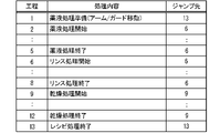
- FIG. 4 is a diagram showing an example of the flow of a series of processes for each recipe step.
- the first column of the table shown in FIG. 4 indicates the execution order of the recipe steps, and the second column indicates the contents of the recipe steps.
- "preparation for chemical solution processing" is set as the first recipe step.
- This recipe step defines a process for preparing for chemical treatment. For example, the movements of arm 41 and guard 7 are defined.
- the recipe step defines the movement of the arm 41 to the processing position and the raising of the guards 72, 73 to the upper position.
- start chemical treatment is set as the second recipe step.
- chemical treatment is set as the third and fourth recipe steps, and “completion of chemical treatment” is set as the fifth recipe step.
- These recipe steps define, for example, the rotation speed of the substrate W, the flow rate of the chemical solution, and the required time. Defined. Required time is the time required for each recipe step. Further, in the recipe step corresponding to "end of chemical solution processing", movement of the arm 41 to the standby position is specified as necessary.
- next process recipe here, rinse processing
- the rinse liquid when the rinse liquid is discharged from the nozzle 31 of the same arm 41, the movement of the arm 41 to the standby position is not defined, and other
- the rinse liquid is discharged from the nozzle 31 of the arm 41, the movement of the arm 41 to the standby position is defined.
- the nozzles 31 of the same arm 41 discharge the rinse liquid.
- start rinsing is set as the sixth recipe step.
- the recipe step "start rinsing” defines the raising of the guards 71 to 73 to the upper position.
- “rinsing” is set as the seventh recipe step
- “end of rinsing” is set as the eighth recipe step.
- These recipe steps define, for example, the rotational speed of the substrate W, the nozzles for discharging the rinse liquid among the nozzles 31, the flow rate of the rinse liquid, and the required time. Further, in the recipe step of "end of rinse process", the movement of the arm 41 to the standby position is defined as necessary.
- start drying is set as the ninth recipe step.
- drying process is set as the tenth and eleventh recipe steps
- drying process end is set as the twelfth recipe step.
- These recipe steps define, for example, the rotation speed of the substrate W and the duration.
- the rotational speed of this recipe step is set to a higher value than the rotational speeds of the chemical liquid treatment and the rinse treatment.
- the descent of the guard 7 to the lower position is defined as necessary.
- recipe process end is set as the 13th recipe step. This recipe step prescribes the movement of various configurations to their home positions, if necessary.
- Information that defines the flow of such a series of processes is stored in the storage device 94 as setting information D1.
- Information that defines the flow of a series of processes is hereinafter also referred to as flow recipe information.
- the control unit 90 controls operations of various components of the substrate processing apparatus 100 based on the setting information D1. Thereby, the substrate processing apparatus 100 can perform a series of processes on the substrate W.
- FIG. 1 Information that defines the flow of such a series of processes is stored in the storage device 94 as setting information D1.
- Information that defines the flow of a series of processes is hereinafter also referred to as flow recipe information.
- the control unit 90 controls operations of various components of the substrate processing apparatus 100 based on the setting information D1. Thereby, the substrate processing apparatus 100 can perform a series of processes on the substrate W.
- the control unit 90 instructs each processing unit 30 to perform first abnormality processing according to the processing content (corresponding to the execution content) being executed. to do Specifically, the control unit 90 causes the processing unit 130 to execute a series of processes from the jump destination set corresponding to the contents of the process being executed as the first abnormal process.
- the third column of the table shows the jump destination corresponding to each recipe step.
- the 13th recipe step is set as the jump destination corresponding to the 1st recipe step. That is, in this example, when an abnormality is detected during the execution of the recipe step "Chemical liquid processing preparation", the processing unit 130 executes a series of processes from the recipe step "Recipe processing end" as the first abnormality processing.
- the processing using the processing liquid (chemical processing and rinsing processing) is performed. ) is not performed, and the recipe step of "recipe process end" after the drying process is executed. Therefore, consumption of the processing liquid can be reduced. Moreover, since the drying process is not performed, the power consumption of the substrate processing apparatus 100 can also be reduced.
- the 6th recipe step is set as the jump destination corresponding to the 2nd to 5th recipe steps.
- the processing unit 130 executes a series of processes from the recipe step of "Start Rinse Processing" as the first abnormality processing. That is, the processing unit 130 sequentially executes the recipe steps from "start of rinse processing" to "end of recipe processing".
- the processing unit 130 can wash away the chemical solution on the substrate W caused by the chemical solution process by the rinsing process, and dry the substrate W by the drying process. Therefore, damage to the substrate W due to the chemical solution can be suppressed.
- the sixth recipe step is set as the jump destination corresponding to the sixth to eighth recipe steps.
- the processing unit 130 executes a series of processes from the "start rinse process" recipe step as the first abnormality process. That is, the processing unit 130 sequentially executes the recipe steps from "start of rinse processing" to "end of recipe processing".
- the processing unit 130 restarts the rinsing process for the substrate W from the beginning in the first abnormal process, the rinsing process for the substrate W can be completed more reliably. Therefore, the chemical solution remaining on the substrate W can be suppressed appropriately.
- the 9th recipe step is set as the jump destination corresponding to the 9th to 12th recipe steps.
- the processing unit 130 executes a series of processes from the recipe step of "start drying process” as the abnormality process. That is, the processing unit 130 sequentially executes recipe steps from "drying process start” to the final "recipe process end".
- the processing unit 130 does not perform the rinsing process in the first abnormality process, so it is possible to reduce the consumption of the rinsing liquid.
- the processing unit 130 restarts the drying process for the substrate W from the beginning in the first abnormal process, the drying process for the substrate W can be completed more reliably. Therefore, the residual rinse liquid on the substrate W can be appropriately suppressed.
- the 13th recipe step is set as the jump destination corresponding to the 13th recipe step.
- the processing unit 130 executes a series of processes from the recipe step of "end of recipe process” as the first error process.
- a plurality of processing units 130 execute a first abnormality process when a certain abnormality occurs in substrate processing apparatus 100 . For example, when the abnormality occurs in one of the processing units 130, the plurality of processing units 130 perform the first abnormality process in response to the detection of the abnormality.
- the one processing unit 130 may terminate the operation without redoing the first abnormality process.
- the one processing unit 130 may execute a second abnormality process different from the first abnormality process. The second abnormality processing will be detailed later.
- the other processing units 130 are likely to be able to complete the first error handling. Therefore, other processing units 130 can rescue the substrate W appropriately.
- the user inputs to the input unit 96 to instruct display of the setting screen SS1.
- the control unit 90 causes the display unit 97 to display the setting screen SS1 in response to the input.
- FIG. 5 is a diagram schematically showing an example of the setting screen SS1.
- the setting screen SS1 illustrated in FIG. 5 includes a table ST1 showing the processing contents (recipe steps here) in the execution order.
- the first column of the table ST1 shows numbers for identifying the processing contents of each row, and the numbers in the first column indicate the execution order of the processing contents.
- the second to (N-1)th columns of Table ST1 show the recipe steps defined in each row.
- the recipe step includes items “AP1” to “AP3”.
- “AP1” to “AP3” are symbols for identifying arms 41 . That is, the processing unit 130 includes three nozzle moving mechanisms 4 here.
- the arm state includes, for example, the position of the arm 41 and the ejection state from each nozzle 31 of the arm 41 .
- the recipe steps may optionally include information such as the position of the guard 7, the rotational speed of the substrate W, the flow rate of the processing liquid, and the like.
- the user makes an input to the input unit 96 to define each processing content.
- the user inputs various pieces of information from the second column to the (N-1)th column into the input unit 96 for each row (that is, for each recipe step).
- the control section 90 sets a series of processes to be executed by the processing unit 130 and causes the display section 97 to display the contents thereof.
- the display unit 97 displays each recipe step in a table ST1 on the setting screen SS1.
- the user inputs to the input unit 96 to specify the jump destination corresponding to each recipe step.
- the control section 90 sets a jump destination corresponding to each recipe step and causes the display section 97 to display the contents.
- the display unit 97 displays jump destinations in a table ST1 on the setting screen SS1.
- the item "RSC" in the Nth column is the item indicating the jump destination.
- the control unit 90 causes the storage device 94 to store the flow recipe information indicating the series of processes set by the user and the jump destination information indicating the jump destination as the setting information D1.
- a “save” button B1 is displayed on the setting screen SS1, and the user operates the input unit 96 to select (click) the button B1.
- the control unit 90 stores the setting information D1 in the storage device 94 in response to the input.
- the control unit 90 specifies a jump destination according to the processing content being executed based on the setting information D1. Then, the control unit 90 causes the processing unit 130 to perform a series of processes from the specified jump destination as the first abnormal process.
- the second abnormality process is executed when an abnormality is detected during execution of the first abnormality process.
- the procedure of this second abnormality process is predetermined and does not depend on the contents of the process being executed when the abnormality is detected.
- the processing conditions for example, the flow rate of the processing liquid and the rotation speed of the substrate W
- the input unit 96 accepts input of processing conditions for the second abnormality processing.
- the second abnormal processing includes, for example, rinsing processing using a predetermined nozzle and drying processing.
- the rinse process of the second abnormality process is rinse process using the fixed nozzle 51 .
- the processing unit 130 even if the processing unit 130 cannot complete the first error handling, it may be possible to complete the second error handling.
- the same abnormality may occur in the one processing unit 130 during execution of the first abnormality process.
- the nozzle 31 is not used in the second abnormality process, a similar abnormality does not occur during execution of the second abnormality process. Therefore, the one processing unit 130 can complete the second error processing.
- the chemical liquid on the substrate W can be replaced with the rinse liquid by the second abnormal process, so damage to the substrate W due to the chemical liquid can be suppressed.
- the control unit 90 may cause the storage device 94 to store a first flag F1 for setting whether the first abnormality process is valid or invalid.
- the input unit 96 receives input for designating whether the first abnormality process is enabled or disabled.
- the control unit 90 raises or lowers the first flag F1 in response to the input.
- the first flag F1 is raised, the first abnormality process is set valid, and when the first flag F1 is lowered, the first abnormality process is set invalid.
- Enabling/disabling of the first error process may be set for each processing unit 130 or may be set commonly for two or more processing units 130 .
- the control unit 90 may cause the storage device 94 to store a second flag F2 for setting whether the second abnormality process is valid or invalid.
- the input unit 96 receives input designating whether the second abnormality process is enabled or disabled.
- the control unit 90 raises or lowers the second flag F2 in response to the input.
- the second flag F2 is raised, the second abnormality process is set valid, and when the second flag F2 is lowered, the second abnormality process is set invalid.
- Enabling/disabling of the second error handling may be set for each processing unit 130 or may be set commonly for two or more processing units 130 .
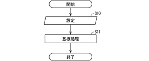
- FIG. 6 is a flow chart showing an example of processing of the substrate processing apparatus 100 .
- step S10 setting step
- the user inputs to the input unit 96 to specify the content of the series of processes and the jump destination.
- the display unit 97 displays recipe steps and jump destinations as described above. While confirming the display section 97 , the user inputs a series of processes and a jump destination to the input section 96 .
- the storage device 94 stores the setting information D1 including the flow recipe information and the jump destination information. By displaying the recipe step and the jump destination on the display unit 97, the user can easily confirm the contents of the first abnormality process and set the jump destination.
- the user inputs enable/disable of the first abnormality process and enable/disable of the second abnormality process to the input unit 96 .
- the control unit 90 stores the first flag F1 and the second flag F2 in the storage device 94 in response to the input.
- the substrate processing apparatus 100 processes the substrate W (step S11: substrate processing step). Specifically, the control unit 90 controls each component of the substrate processing apparatus 100 based on the setting information D1. As a result, the substrates W in the carrier C are sequentially transported to the processing units 130 , and a series of processes are performed in each processing unit 130 . When all the substrates W are processed by the processing unit 130 and transported to the carrier C without any abnormality occurring in the substrate processing apparatus 100, the substrate processing apparatus 100 finishes processing.
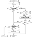
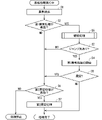
- FIG. 7 is a flowchart showing an example of the operation of the substrate processing apparatus 100 when an abnormality occurs in the substrate processing apparatus 100.
- FIG. FIG. 7 shows the flow of processing for one processing unit 130 .
- the one processing unit 130 is hereinafter also referred to as its own processing unit 130 .
- one of the sensors 10 of the substrate processing apparatus 100 detects an abnormality and outputs the detection result to the control section 90 (step S1: detection step).
- the abnormalities referred to here are abnormalities in which the guard 7 does not move to a predetermined position, abnormalities in which the substrate holder 2 does not rotate, abnormalities in which the detachable cover is removed from the chamber 1 during processing of the substrate W, and processing liquid reaching each nozzle 31 .
- control unit 90 determines whether the first abnormality process is valid or invalid (step S2). Specifically, the control unit 90 determines whether or not the first flag F1 stored in the storage device 94 has risen.
- the control unit 90 determines whether or not a jump destination corresponding to the content of the process being executed is set based on the setting information D1 (step S3). Specifically, the control unit 90 checks the setting information D1 stored in the storage device 94 .
- the case where the jump destination is not set includes the case where the jump destination information itself is not set and the case where information such as a symbol irrelevant to the jump destination is set.
- the control unit 90 causes the self-processing unit 130 to execute a series of processes from the processing contents of the jump destination (step S4: first abnormality processing step).
- the self-processing unit 130 does not continue the series of processes as it is, but executes the series of processes (first abnormal process) starting from the processing content of the jump destination.
- the control unit 90 determines whether or not the sensor 10 in its own processing unit 130 has detected an abnormality during execution of the first abnormality process (step S5). That is, the control unit 90 determines whether or not an abnormality that hinders execution of the first abnormality process has been detected.
- the control unit 90 continues abnormality monitoring by the sensor 10 at least until the first abnormality processing is completed.
- the self-processing unit 130 can complete the first abnormality processing. For example, if the abnormality in step S1 occurs in another processing unit 130, the own processing unit 130 can complete more appropriate first abnormality processing.
- control unit 90 determines whether or not the second abnormality process is effective (step S6). Specifically, the control unit 90 determines whether or not the second flag F2 stored in the storage device 94 is raised.
- the control section 90 causes the self-processing unit 130 to execute the second abnormality processing (step S7: second abnormality processing step).
- the second abnormal process includes, for example, a rinse process of discharging the rinse liquid from the fixed nozzle 51 and a drying process after the rinse process. According to this, even if the chemical liquid exists on the substrate W, the substrate W can be dried after the chemical liquid is replaced with the rinsing liquid. Therefore, damage to the substrate W due to the chemical solution can be suppressed.
- control section 90 may cause the processing unit 130 to end the second abnormality processing in the middle.
- control section 90 may cause the self-processing unit 130 to redo the second abnormality process a predetermined number of times.
- the control section 90 may cause the self-processing unit 130 to terminate the second abnormality process in the middle when an abnormality occurs in all the second abnormality processes that have been redone from the beginning.
- step S6 determines whether the second abnormality process is effective. Further, even when the jump destination corresponding to the process being executed is not set (step S3: NO), the control unit 90 determines whether or not the second abnormality process is effective (step S6).
- step S6 NO
- the control section 90 stops the operation of the processing unit 130 itself. In other words, the self-processing unit 130 does not perform the abnormal processing on the substrate W and stops its operation.
- each processing unit 130 can complete the first anomaly process (steps S1 to S5).
- the control unit 90 continues the first abnormality process because there is no problem in continuing the first abnormality process.
- the abnormality is, for example, an abnormality in the driving system of the nozzle moving mechanism 4 .
- the one processing unit 130 Since such an anomaly also occurs while the one processing unit 130 is executing the first anomaly processing, the one processing unit 130 performs the second anomaly processing in response to the detection of the anomaly (step S1 to step S7).
- the other processing units 130 can complete the first abnormality processing (steps S1 to S5).
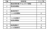
- FIG. 8 is a diagram showing an example of substrate processing and jump destinations.
- the jump destination corresponding to the processing contents of chemical liquid processing is not set.
- jump destinations corresponding to the second to fifth recipe steps are not set.
- the processing unit 130 does not perform the first abnormality process, but performs the second abnormality process (steps S1 to S3, steps S6 and S7).
- each processing unit 130 performs the first abnormality process instead of continuing the series of processes (step S4). Specifically, each processing unit 130 performs a series of processes from a jump destination corresponding to the processing content that was being executed when the abnormality occurred as the first abnormality process. That is, the first abnormality process corresponds to part of the series of processes. Since the series of processes is defined by the content of processing suitable for the substrate W, the first abnormal process is also suitable for the substrate W. FIG.
- the chemical solution on the substrate W can be appropriately replaced with the rinse solution in a series of processes.
- the same rinse processing as the series of processing is performed in the first abnormality processing. Therefore, even in the first abnormal process, the chemical liquid on the substrate W can be appropriately replaced with the rinse liquid.
- processing is performed so that the pattern does not collapse in a series of processes.
- the processing unit 130 performs chemical liquid processing, first rinsing processing, hydrophobic processing, second rinsing processing, and drying processing in this order as a series of processing.
- the hydrophobizing process is a process of supplying a hydrophobizing liquid to the substrate W to form a hydrophobizing film on the surface of the pattern of the substrate W, and the second rinsing process replaces the hydrophobizing liquid on the substrate W with the rinse liquid. It is a process to By performing the hydrophobizing treatment in this way, it is possible to suppress the collapse of the pattern during the drying treatment.
- the user should set the recipe step corresponding to the start of the first rinse process as the jump destination corresponding to the chemical liquid process.
- the processing unit 130 executes a series of processes from the first rinse process as the first abnormality process. That is, the processing unit 130 performs the first rinsing process, the hydrophobic process, the second rinsing process, and the drying process in this order as the first abnormal process. Therefore, even in the first abnormality process, pattern collapse can be suppressed more reliably.
- the first abnormal process is the same as a part of the series of processes, more appropriate abnormal process for the substrate W can be performed. Therefore, various problems that may occur with respect to the substrate W can be suppressed or avoided.
- the user can set a more appropriate first abnormality process.
- the user may set the processing content of the drying process as a jump destination corresponding to the processing content of the drying process (see also FIG. 4).
- the processing unit 130 performs a series of processes from the drying process as the first abnormality process. In other words, the processing unit 130 does not perform rinse processing in the first abnormality processing. Therefore, consumption of the rinse liquid and power consumption of the substrate processing apparatus 100 can be reduced.
- the user may select a post-drying process as a jump destination corresponding to a process content (for example, "preparation for chemical liquid process") in a situation where the process liquid has not yet been discharged and the process liquid has not adhered to the substrate W. It is preferable to set the contents (for example, "recipe processing end") (see also FIG. 4).
- the processing unit 130 encounters an abnormality during execution of the processing content before discharging the processing liquid, the processing unit 130 performs a series of processing from the processing content after the drying processing. In other words, the processing unit 130 does not perform the rinsing process and the drying process in the first abnormality process. Therefore, the consumption of the rinse liquid can be reduced, and the power consumption of the substrate processing apparatus 100 can be further reduced.
- the processing unit 130 in which the abnormality occurs does not redo the first abnormality process, but performs the first abnormality process. performs different second abnormality processing (steps S5 and S6).
- the second abnormality process a rinsing process using a preset nozzle (for example, the fixed nozzle 51) and a drying process after the rinsing process are performed.
- the processing unit 130 can complete the second abnormality processing. For example, even if the nozzle moving mechanism 4 malfunctions in the first abnormality process, the rinse process using the fixed nozzle 51 can be performed in the second abnormality process. Therefore, even if the first abnormal process cannot be performed, the second abnormal process can remove the processing liquid from the substrate W and dry it. Therefore, damage to the substrate W due to the chemical solution can be suppressed.
- the first flag F1 is set to indicate whether the first abnormality process is valid or invalid. According to this, usability can be improved.
- the second flag F2 is set to indicate whether the second abnormality process is valid or invalid. Usability can be improved also by this.
- the jump destination corresponding to the recipe step "prepare for chemical liquid processing” was the recipe step "end of recipe processing" (see FIG. 4).
- the user may set the recipe step "preparation for chemical processing” as a jump destination corresponding to the recipe step "preparation for chemical processing”.
- the processing unit 130 executes a series of processes from the recipe step of "preparation for chemical processing" as the first error processing.
- the recipe step "preparation for chemical processing” may be performed redundantly, but since this recipe step does not supply the chemical liquid to the substrate W, there is no problem even if the redundant operation occurs. Then, the processing unit 130 performs chemical liquid processing, rinsing processing, and drying processing in this order as the first abnormal processing. Therefore, if no abnormality occurs in the first abnormality process, the processing unit 130 can substantially complete a series of processes. Therefore, the substrate W can be rescued without being discarded, and the substrate W can be directly advanced to the next manufacturing process.
- the processing unit 130 performs the second abnormality process. As a result, damage to the substrate W due to the chemical solution can be suppressed.
- the blocking plate 6 is not used in the series of processes, but the blocking plate 6 may be used.
- the blocking plate 6 may stop at the close position during the chemical solution treatment and the drying treatment.
- the recipe step "Chemical solution preparation” defines the lowering of the blocking plate 6 to the adjacent position
- the recipe step "Recipe processing end” defines the lifting of the blocking plate 6 to the home position.
- the recipe step "end of recipe processing” may be set as a jump destination corresponding to the recipe step "preparation for chemical liquid processing". If an abnormality occurs during the execution of "preparation for chemical liquid processing", the processing unit 130 performs a series of processes from the recipe step of "completion of recipe processing", so that the blocking plate 6 can be raised to the home position. Also in this case, since the rinsing process and the drying process are not performed, the consumption of the processing liquid and the power consumption can be reduced.
- the control unit 90 may automatically set jump destinations for some or all of the recipe steps of the series of processes.
- control unit 90 automatically changes the jump destination corresponding to the recipe step of the processing content (for example, "preparation for chemical liquid processing") before supplying the processing liquid to the recipe step after the drying processing (for example, "recipe processing end”).
- Recipe steps subsequent to the recipe step after the drying process include a recipe step in which various drive mechanisms (the nozzle moving mechanism 4, the lifting mechanism 68 and the lifting mechanism 74) move to the standby position.
- control unit 90 may update the jump destination in response to the input. In other words, the control unit 90 may update the automatically set jump destination to the jump destination input by the user.
- the user can more easily set the jump destination, so usability can be further improved.
- FIG. 9 is a flow chart showing an example of the operation of the substrate processing apparatus 100 according to the second embodiment.
- step S8 continuation process step
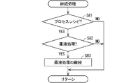
- FIG. 10 is a flowchart illustrating a specific example of continued processing.
- the control unit 90 determines whether or not the processing content being executed when the abnormality occurs is the processing content specified in the process recipe (step S81). When the processing content being executed is not the processing content specified by the process recipe, the control unit 90 terminates the continuation processing.
- the control unit 90 determines whether or not the processing content being executed is chemical liquid processing (step S82). When the content of the process being executed is not the chemical liquid process, the control unit 90 terminates the continuation process.
- control unit 90 continues the chemical processing (step S83). It should be noted that the controller 90 may terminate the chemical processing when the chemical processing cannot be continued due to an abnormality occurring during the chemical processing.
- control unit 90 executes the steps after step S3 in the same manner as in the first embodiment (see FIG. 9).
- the processing unit 130 when an abnormality occurs in the substrate processing apparatus 100 while the processing unit 130 is performing chemical processing, the processing unit 130 continues the chemical processing. Therefore, for example, when an abnormality occurs in another processing unit 130, the processing unit 130 can complete the chemical processing.
- the processing unit 130 performs the first abnormality processing or the second abnormality processing as in the first embodiment. According to this, even if the chemical solution processing is not set as the jump destination in the first abnormality processing, the chemical solution processing can be completed. Note that if the chemical solution process is performed in the first abnormality process as well, the chemical solution process is performed redundantly, so the continuation process may be performed only when the chemical solution process is not set to the jump destination.
- the chemical liquid process is continued in the continuation process (step S83). Then, if the chemical treatment can be completed without causing any abnormality during the continuation of the chemical treatment, the substrate W after the abnormal treatment can be directly advanced to the next manufacturing process.
- FIG. 11 is a flowchart showing another example of continued processing.
- the control unit 90 acquires the remaining time of chemical processing (step S84).
- the remaining time is the remaining time from the current time to the end time of chemical treatment.
- the control unit 90 calculates the remaining time based on the processing time of the chemical treatment specified by the flow recipe information and the elapsed time from the start of the chemical treatment. Elapsed time is measured, for example, by a timer circuit.
- the control unit 90 determines whether or not the remaining time is equal to or less than the threshold (step S85).
- the threshold is set in advance and stored in the storage device 94, for example.
- the chemical treatment can be completed in a short time, so the controller 90 continues the chemical treatment (step S83).
- the control unit 90 stops the chemical solution processing and terminates the continuous processing.
- control unit 90 continues the chemical processing when the remaining time of the chemical processing is short, and does not continue the chemical processing when the remaining time of the chemical processing is long. According to this, it is possible to avoid excessively long time required for the first abnormality process when an abnormality occurs. In other words, it is possible to finish the error processing in a shorter time.
- the substrate processing apparatus 100 has been described in detail as above, the above description is an example in all aspects, and the substrate processing apparatus 100 and the substrate processing method are not limited thereto. It is understood that numerous variations not illustrated can be envisioned without departing from the scope of this disclosure. Each configuration described in each of the above embodiments and modifications can be appropriately combined or omitted as long as they do not contradict each other.
Landscapes
- Cleaning Or Drying Semiconductors (AREA)
- Weting (AREA)
Priority Applications (2)
| Application Number | Priority Date | Filing Date | Title |
|---|---|---|---|
| CN202280042202.5A CN117501413A (zh) | 2021-06-16 | 2022-04-15 | 基板处理方法、基板处理装置以及程序 |
| KR1020237041638A KR102989360B1 (ko) | 2021-06-16 | 2022-04-15 | 기판 처리 방법, 기판 처리 장치 및 프로그램 |
Applications Claiming Priority (2)
| Application Number | Priority Date | Filing Date | Title |
|---|---|---|---|
| JP2021-100200 | 2021-06-16 | ||
| JP2021100200A JP7682711B2 (ja) | 2021-06-16 | 2021-06-16 | 基板処理方法、基板処理装置およびプログラム |
Publications (1)
| Publication Number | Publication Date |
|---|---|
| WO2022264675A1 true WO2022264675A1 (ja) | 2022-12-22 |
Family
ID=84527104
Family Applications (1)
| Application Number | Title | Priority Date | Filing Date |
|---|---|---|---|
| PCT/JP2022/017931 Ceased WO2022264675A1 (ja) | 2021-06-16 | 2022-04-15 | 基板処理方法、基板処理装置およびプログラム |
Country Status (5)
| Country | Link |
|---|---|
| JP (1) | JP7682711B2 (cg-RX-API-DMAC7.html) |
| KR (1) | KR102989360B1 (cg-RX-API-DMAC7.html) |
| CN (1) | CN117501413A (cg-RX-API-DMAC7.html) |
| TW (2) | TWI899788B (cg-RX-API-DMAC7.html) |
| WO (1) | WO2022264675A1 (cg-RX-API-DMAC7.html) |
Cited By (1)
| Publication number | Priority date | Publication date | Assignee | Title |
|---|---|---|---|---|
| WO2025192673A1 (ja) * | 2024-03-13 | 2025-09-18 | 東京エレクトロン株式会社 | 情報処理方法、情報処理装置及びコンピュータプログラム |
Citations (2)
| Publication number | Priority date | Publication date | Assignee | Title |
|---|---|---|---|---|
| JP2010109347A (ja) * | 2008-10-03 | 2010-05-13 | Dainippon Screen Mfg Co Ltd | 基板処理装置および異常処理方法 |
| JP2015128087A (ja) * | 2013-12-27 | 2015-07-09 | 東京エレクトロン株式会社 | 基板処理装置および基板処理方法 |
Family Cites Families (7)
| Publication number | Priority date | Publication date | Assignee | Title |
|---|---|---|---|---|
| JP4071139B2 (ja) * | 2003-03-26 | 2008-04-02 | 大日本スクリーン製造株式会社 | 基板処理装置の制御方法 |
| JP4490797B2 (ja) * | 2004-01-23 | 2010-06-30 | 大日本スクリーン製造株式会社 | 基板処理装置 |
| JP5452349B2 (ja) * | 2010-05-11 | 2014-03-26 | 東京エレクトロン株式会社 | 被処理体の搬送方法、被処理体の搬送装置、及び、プログラム |
| JP5459279B2 (ja) * | 2011-09-02 | 2014-04-02 | 東京エレクトロン株式会社 | 基板処理装置、基板処理方法及び記憶媒体 |
| JP5673577B2 (ja) * | 2012-02-07 | 2015-02-18 | 東京エレクトロン株式会社 | 基板処理装置、基板処理方法及び記憶媒体 |
| JP5935676B2 (ja) * | 2012-12-07 | 2016-06-15 | 東京エレクトロン株式会社 | 基板処理装置、基板装置の運用方法及び記憶媒体 |
| JP7303678B2 (ja) * | 2019-07-08 | 2023-07-05 | 東京エレクトロン株式会社 | 基板処理システム及び基板処理方法 |
-
2021
- 2021-06-16 JP JP2021100200A patent/JP7682711B2/ja active Active
-
2022
- 2022-04-15 CN CN202280042202.5A patent/CN117501413A/zh active Pending
- 2022-04-15 WO PCT/JP2022/017931 patent/WO2022264675A1/ja not_active Ceased
- 2022-04-15 KR KR1020237041638A patent/KR102989360B1/ko active Active
- 2022-04-20 TW TW113100683A patent/TWI899788B/zh active
- 2022-04-20 TW TW111114935A patent/TWI832216B/zh active
Patent Citations (2)
| Publication number | Priority date | Publication date | Assignee | Title |
|---|---|---|---|---|
| JP2010109347A (ja) * | 2008-10-03 | 2010-05-13 | Dainippon Screen Mfg Co Ltd | 基板処理装置および異常処理方法 |
| JP2015128087A (ja) * | 2013-12-27 | 2015-07-09 | 東京エレクトロン株式会社 | 基板処理装置および基板処理方法 |
Cited By (1)
| Publication number | Priority date | Publication date | Assignee | Title |
|---|---|---|---|---|
| WO2025192673A1 (ja) * | 2024-03-13 | 2025-09-18 | 東京エレクトロン株式会社 | 情報処理方法、情報処理装置及びコンピュータプログラム |
Also Published As
| Publication number | Publication date |
|---|---|
| TW202418014A (zh) | 2024-05-01 |
| KR20240004886A (ko) | 2024-01-11 |
| TWI899788B (zh) | 2025-10-01 |
| JP7682711B2 (ja) | 2025-05-26 |
| TWI832216B (zh) | 2024-02-11 |
| JP2022191764A (ja) | 2022-12-28 |
| CN117501413A (zh) | 2024-02-02 |
| TW202301048A (zh) | 2023-01-01 |
| KR102989360B1 (ko) | 2026-07-09 |
Similar Documents
| Publication | Publication Date | Title |
|---|---|---|
| KR100979979B1 (ko) | 액처리 장치 및 액처리 방법 | |
| KR101238123B1 (ko) | 세정 장치, 세정 방법, 및 컴퓨터 판독 가능한 매체 | |
| US10381257B2 (en) | Substrate conveying robot and substrate processing system with pair of blade members arranged in position out of vertical direction | |
| JP5885989B2 (ja) | 液処理装置、液処理方法および記憶媒体 | |
| JP5426301B2 (ja) | 基板処理装置 | |
| JP5390873B2 (ja) | 基板処理方法および基板処理装置 | |
| JP2022191764A (ja) | 基板処理方法、基板処理装置およびプログラム | |
| JP2016042518A (ja) | 基板処理装置および基板処理方法 | |
| KR102223972B1 (ko) | 기판 처리 장치 및 기판 처리 방법 | |
| JP6640630B2 (ja) | 基板処理装置および基板処理方法 | |
| KR20230062497A (ko) | 기판 처리 방법 | |
| JP2009111163A (ja) | 基板処理方法および基板処理装置 | |
| JP2010238758A (ja) | 基板処理装置 | |
| JP2868722B2 (ja) | 基板処理装置 | |
| JP7002605B2 (ja) | 基板処理装置および基板処理方法 | |
| JP6443806B2 (ja) | 基板処理装置 | |
| JP2023117776A (ja) | 基板処理装置、および処理カップの洗浄方法 | |
| JP2008205311A (ja) | 基板処理装置 | |
| KR102075685B1 (ko) | 포토 마스크 세정 장치 및 포토 마스크 세정 방법 | |
| KR102838925B1 (ko) | 기판 처리 장치 및 기판 처리 방법 | |
| JP7688591B2 (ja) | 基板処理装置および基板処理方法 | |
| JP2014120645A (ja) | 基板処理装置及びその方法 | |
| JP2868721B2 (ja) | 基板処理装置 | |
| EP4672304A1 (en) | SUBSTRATE TREATMENT DEVICE AND SUBSTRATE TREATMENT METHOD | |
| KR20240086536A (ko) | 기판 처리 방법 및 기판 처리 장치 |
Legal Events
| Date | Code | Title | Description |
|---|---|---|---|
| 121 | Ep: the epo has been informed by wipo that ep was designated in this application |
Ref document number: 22824670 Country of ref document: EP Kind code of ref document: A1 |
|
| ENP | Entry into the national phase |
Ref document number: 20237041638 Country of ref document: KR Kind code of ref document: A |
|
| WWE | Wipo information: entry into national phase |
Ref document number: 1020237041638 Country of ref document: KR |
|
| WWE | Wipo information: entry into national phase |
Ref document number: 202280042202.5 Country of ref document: CN |
|
| NENP | Non-entry into the national phase |
Ref country code: DE |
|
| 122 | Ep: pct application non-entry in european phase |
Ref document number: 22824670 Country of ref document: EP Kind code of ref document: A1 |
|
| WWR | Wipo information: refused in national office |
Ref document number: 1020237041638 Country of ref document: KR |
|
| WWC | Wipo information: continuation of processing after refusal or withdrawal |
Ref document number: 1020237041638 Country of ref document: KR |