WO2022264603A1 - プラズマ源及び当該プラズマ源を用いた原子時計 - Google Patents
プラズマ源及び当該プラズマ源を用いた原子時計 Download PDFInfo
- Publication number
- WO2022264603A1 WO2022264603A1 PCT/JP2022/013803 JP2022013803W WO2022264603A1 WO 2022264603 A1 WO2022264603 A1 WO 2022264603A1 JP 2022013803 W JP2022013803 W JP 2022013803W WO 2022264603 A1 WO2022264603 A1 WO 2022264603A1
- Authority
- WO
- WIPO (PCT)
- Prior art keywords
- magnet
- magnetic pole
- electrode
- plasma source
- magnetic field
- Prior art date
- Legal status (The legal status is an assumption and is not a legal conclusion. Google has not performed a legal analysis and makes no representation as to the accuracy of the status listed.)
- Ceased
Links
Images






Classifications
-
- H—ELECTRICITY
- H05—ELECTRIC TECHNIQUES NOT OTHERWISE PROVIDED FOR
- H05H—PLASMA TECHNIQUE; PRODUCTION OF ACCELERATED ELECTRICALLY-CHARGED PARTICLES OR OF NEUTRONS; PRODUCTION OR ACCELERATION OF NEUTRAL MOLECULAR OR ATOMIC BEAMS
- H05H1/00—Generating plasma; Handling plasma
- H05H1/02—Arrangements for confining plasma by electric or magnetic fields; Arrangements for heating plasma
- H05H1/10—Arrangements for confining plasma by electric or magnetic fields; Arrangements for heating plasma using externally-applied magnetic fields only, e.g. Q-machines, Yin-Yang, base-ball
-
- G—PHYSICS
- G04—HOROLOGY
- G04F—TIME-INTERVAL MEASURING
- G04F5/00—Apparatus for producing preselected time intervals for use as timing standards
- G04F5/14—Apparatus for producing preselected time intervals for use as timing standards using atomic clocks
-
- H—ELECTRICITY
- H01—ELECTRIC ELEMENTS
- H01J—ELECTRIC DISCHARGE TUBES OR DISCHARGE LAMPS
- H01J41/00—Discharge tubes for measuring pressure of introduced gas or for detecting presence of gas; Discharge tubes for evacuation by diffusion of ions
- H01J41/12—Discharge tubes for evacuating by diffusion of ions, e.g. ion pumps, getter ion pumps
- H01J41/18—Discharge tubes for evacuating by diffusion of ions, e.g. ion pumps, getter ion pumps with ionisation by means of cold cathodes
-
- H—ELECTRICITY
- H03—ELECTRONIC CIRCUITRY
- H03L—AUTOMATIC CONTROL, STARTING, SYNCHRONISATION OR STABILISATION OF GENERATORS OF ELECTRONIC OSCILLATIONS OR PULSES
- H03L7/00—Automatic control of frequency or phase; Synchronisation
- H03L7/26—Automatic control of frequency or phase; Synchronisation using energy levels of molecules, atoms, or subatomic particles as a frequency reference
-
- H—ELECTRICITY
- H05—ELECTRIC TECHNIQUES NOT OTHERWISE PROVIDED FOR
- H05H—PLASMA TECHNIQUE; PRODUCTION OF ACCELERATED ELECTRICALLY-CHARGED PARTICLES OR OF NEUTRONS; PRODUCTION OR ACCELERATION OF NEUTRAL MOLECULAR OR ATOMIC BEAMS
- H05H1/00—Generating plasma; Handling plasma
- H05H1/24—Generating plasma
Definitions
- the present invention relates to a plasma source and an atomic clock using the plasma source.
- Small cells sealed in ultra-high vacuum are expected to be applied to various innovative devices.
- Such an ultra-high vacuum small cell is realized by airtightly sealing the cell in a medium vacuum (10 ⁇ 1 to 1 Pa) and then evacuating the cell from the outside using an ultra-high vacuum pump.
- Ion pumps are generally widely used as ultra-high vacuum pumps, and plasma sources capable of highly efficient discharge are used inside the ion pumps.
- MEMS Micro Electro Mechanical Systems
- a technique is known that realizes a structure similar to that of an ion pump by a MEMS process (microfabrication and anodic bonding).
- the N pole of the first magnet and the S pole of the second magnet are opposed to each other, and the first cathode electrode made of silicon is placed on the side of the first magnet, and the second cathode electrode made of silicon is placed on the side of the second magnet.
- a cathode electrode and a silicon anode electrode are positioned to provide a space between the first cathode electrode and the second cathode.
- the cathode electrode is arranged in the center
- the anode electrode is arranged on substantially the same plane as the cathode electrode so as to surround the cathode electrode on the outer side
- magnets are arranged above and below the cathode electrode and the anode electrode so that different magnetic poles face each other.
- Other techniques are also known. As a result, the electrons are confined to cause discharge, and the electrons collide with the residual gas to be exhausted. Even with such a technique, it is not possible to discharge with high efficiency in an ultra-high vacuum state of about 10 ⁇ 5 Pa or less.
- a magnetron sputtering method is known as a method for forming a film on a substrate.
- this technique aims at film formation on a substrate, this technique cannot be applied as it is to the problem of highly efficient discharge in an ultra-high vacuum state.
- one object of the present invention is to provide a compact plasma source that enables highly efficient discharge in an ultra-high vacuum.
- the plasma source according to the first aspect of the present invention includes (A) a first magnet, and (B) a second magnetic pole different from the first magnetic pole with respect to the first magnetic pole of the first magnet.
- a second magnet arranged to face and (C) a second magnetic pole different from the first magnetic pole directed in the same direction as the direction of the first magnetic pole of the first magnet, a third magnet arranged to surround the magnet; and (D) a first magnetic pole different from the second magnetic pole faces the second magnetic pole of the third magnet, and the second magnet
- E a first electrode provided on the side of the first magnetic pole of the first magnet and the second magnetic pole of the third magnet
- a plasma source includes (A) a first magnet, and (B) a second magnetic pole different from the first magnetic pole with respect to the first magnetic pole of the first magnet.
- a second magnet arranged to face and (C) a second magnetic pole different from the first magnetic pole directed in the same direction as the direction of the first magnetic pole of the first magnet, a third magnet arranged to surround the magnet; and (D) a first magnetic pole different from the second magnetic pole faces the second magnetic pole of the third magnet, and the second magnet
- E a first electrode provided on the side of the first magnetic pole of the first magnet and the second magnetic pole of the third magnet;
- the first G
- a second electrode provided on the side of the second magnetic pole of the second magnet and the first magnetic pole of the fourth magnet, and (G) higher than the first electrode and the second electrode It is adapted to be energized to a potential and has a third electrode positioned between the first and second electrodes. Then, the shorter one of the distance between the first magnet and the second magnet and the
- FIG. 1 is a diagram showing an outline of a plasma source according to the first embodiment.
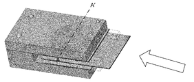
- FIG. 2 is a schematic diagram of a plasma source according to the first embodiment.
- FIG. 3 is a diagram for explaining the arrangement of magnets and the like in the plasma source according to the first embodiment.
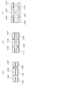
- FIGS. 4(a) to 4(c) are diagrams showing examples of magnetic force line distribution for each inter-magnet distance ratio.
- FIGS. 5(a) to 5(c) are diagrams showing examples of magnetic force line distribution for each inter-magnet distance ratio.
- FIG. 6 is a diagram showing an example of magnetic force intensity distribution in the Y direction.
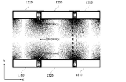
- FIG. 7 is a diagram showing an example of magnetic force intensity distribution in the X direction.
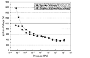
- FIG. 8 is a diagram for explaining the effects of the plasma source according to the first embodiment.
- FIG. 9 is a diagram showing a configuration example when the plasma source is used as an ion pump.
- FIG. 10 is a diagram showing an outline of a small cooled atomic clock.
- FIG. 11 is a diagram showing an outline of a small cooled atomic clock.
- FIG. 12 is a diagram showing an embodiment in which the plasma source is used as a vacuum pump.
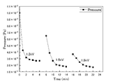
- FIG. 13 is a diagram showing the effect of using the plasma source as a vacuum pump.
- FIG. 1 shows a configuration example of a plasma source according to this embodiment.
- the plasma source according to this embodiment is a combination of the yoke 1100 shown in FIG. 1(a) and the cell section 1500 shown in FIG. 1(b).
- the yoke 1100 has an upper arm 1200 and a lower arm 1300 with a gap 1400 provided between the upper arm 1200 and the lower arm 1300 .
- a cell portion 1500 is inserted into this gap 1400 . That is, the vertical length of the void 1400 is slightly longer than the thickness of the cell portion 1500 .
- Upper arm 1200 includes a cylindrical magnet 1220 and a cylindrical magnet 1210 surrounding cylindrical magnet 1220 . That is, the inner diameter of cylindrical magnet 1210 is larger than the diameter of cylindrical magnet 1220 .
- the center point of cylindrical magnet 1220 viewed from the top and the center point of cylindrical magnet 1210 viewed from the top are arranged to match.
- the thickness of cylindrical magnet 1210 and the thickness of cylindrical magnet 1220 are the same, and magnets having the same strength are used.
- the lower surface of cylindrical magnet 1210 and the lower surface of cylindrical magnet 1220 are arranged to match the lower surface of upper arm 1200 .
- Lower arm 1300 includes a cylindrical magnet 1320 and a cylindrical magnet 1210 surrounding cylindrical magnet 1320 . That is, the inner diameter of cylindrical magnet 1310 is larger than the diameter of cylindrical magnet 1320 .
- the center point of cylindrical magnet 1320 viewed from the top and the center point of cylindrical magnet 1310 viewed from the top are arranged to match.
- the thickness of cylindrical magnet 1310 and the thickness of cylindrical magnet 1320 are the same, and magnets having the same strength are used.
- the upper surface of cylindrical magnet 1310 and the upper surface of cylindrical magnet 1320 are arranged to coincide with the upper surface of lower arm 1300 . It should be noted that columnar elements with no reference numerals in FIG. 1(a) are design connections and the like that are irrelevant to the following description, so description thereof will be omitted.
- cylindrical magnets 1210 and 1310 and cylindrical magnets 1220 and 1320 are magnets of the same strength.
- the magnets may be Neodymium or Samarium Cobalt magnets.
- the cylindrical magnet 1220 and the cylindrical magnet 1320 have the same shape, and the cylindrical magnet 1210 and the cylindrical magnet 1310 also have the same shape.
- the center point of the cylindrical magnet 1220 as seen from above, the center point of the cylindrical magnet 1210 as seen from the upper surface, the center point of the cylindrical magnet 1320 as seen from the upper surface, and the upper surface of the cylindrical magnet 1310 arranged so that it coincides with the center point seen from
- the cell part 1500 includes a flat upper electrode 1510 made of silicon, a flat lower electrode 1530 made of silicon, spacers 1541 to 1543 made of glass, and between the upper electrode 1510 and the lower electrode 1530 . and a plate-shaped electrode 1520 which is held by spacers 1541 to 1543 and the like and provided with a hole 1521 . Note that some spacers, such as the spacer 1541 and the spacer under the electrode 1520, do not appear in FIG. 1 for convenience of illustration.
- a voltage having a potential higher than that of the upper electrode 1510 and the lower electrode 1530 is applied to the electrode 1520 .
- top electrode 1510 and bottom electrode 1530 are grounded and electrode 1520 is applied with a positive voltage.
- electrode 1520 is retained intermediate top electrode 1510 and bottom electrode 1530 .
- the hole 1521 is circular and its diameter is equal to or greater than the inner diameter of the cylindrical magnets 1210 and 1310 . More preferably, the center of the hole 1521 and the central points of the cylindrical magnets 1220 and 1320 viewed from above are aligned. However, the shape of the hole 1521 is arbitrary. Hole 1521 is left open to form space 1700 shown in FIG.
- the cell portion 1500 is shown as if there are spaces on the left and right sides. .
- FIG. 2 schematically shows a state in which the yoke 100 and the cell portion 1500 are combined.
- the cross section is cut along the dashed line AA' and viewed in the direction of the arrow will be described.
- FIG. 3 is a diagram showing the outline of the cross section.
- the columnar magnets 1220 have their south poles directed toward the opposing columnar magnets 1320 and the columnar magnets 1320 have their north poles toward the opposing columnar magnets 1220 .
- the cylindrical magnets 1210 have their north poles oriented toward the opposing cylindrical magnets 1310 , and the cylindrical magnets 1310 have their south poles oriented toward the opposing cylindrical magnets 1210 . Note that the S pole and the N pole may be reversed.
- a magnetic circuit of cylindrical magnets 1220 and 1320 and cylindrical magnets 1210 and 1310 generates a magnetron magnetic field Q and a parallel magnetic field P having a certain strength or more in order to confine the plasma at high density.
- the direction from the lower arm 1300 to the upper arm 1200 facing the lower arm 1300 is defined as the Y direction
- the direction orthogonal to the Y direction is defined as the X direction.
- Electrons cannot travel from sparse to dense magnetic field lines (weak to strong magnetic field strength) and are bounced back. Electrons cannot travel in the Y direction due to the magnetron magnetic field Q. Also, since a zero magnetic field region is generated between the upper and lower magnetron magnetic fields Q, electrons cannot move across the magnetic lines of force from the zero magnetic field region. Furthermore, it cannot advance in the X direction due to the parallel magnetic field P as well. Therefore, the plasma is confined in the region R, and high-density plasma can be generated.
- cylindrical magnets 1220 and 1320 have a diameter of 7 mm, and cylindrical magnets 1210 and 1310 have an outer diameter of 20 mm and an inner diameter of 10 mm.
- the distance between the upper electrode 1510 and the lower electrode 1530 is 4.4 mm.
- a small plasma source is assumed, and the distance between upper electrode 1510 and lower electrode 1530 is assumed to be about 20 mm at the longest.
- the Debye length (plasma size) ⁇ D is 1/10 or less of the above distance (1 mm or less because two plasmas are generated vertically).
- the Debye length is 1 mm or less at a degree of vacuum of 10 ⁇ 4 Pa.
- the Debye length (plasma size) exceeds 1/10 of the above distance, the number of charged particles that collide with the wall and disappear is greater than the number of charged particles generated from the electrodes, and the plasma cannot be maintained. .
- the value obtained by dividing the shortest distance between the magnet in upper arm 1200 and the magnet in lower arm 1300 facing the magnet by the average thickness of the magnets used is It is defined as the distance ratio between magnets.
- the thicknesses of the magnets are all the same T, and the distances between the magnets in the upper arm 1200 and the magnets in the lower arm 1300 that face the magnets are all the same L as well. In such a case, L/T becomes the inter-magnet distance ratio.
- the inter-magnet distance ratio L/T is a small value, for example, a value of 0.5, the magnets are too close and the magnetron magnetic field of sufficient strength is generated, as shown in the simulation results schematically shown in FIG. Not generated.
- the inter-magnet distance ratio L/T increases to, for example, 1.0, a magnetron magnetic field is generated and high-density plasma can be generated, as shown in the simulation results schematically shown in FIG. 4(b). .
- Further increasing the inter-magnet distance ratio L/T to, for example, 2.5 produces sufficiently strong magnetron magnetic field and parallel magnetic field.
- the distance ratio L/T between magnets is 1 or more and 10 or less, it can be used as a general plasma source. Further, in order to confine the plasma at a higher density, it is preferable that the distance ratio L/T between the magnets is 2.5 or more and 5 or less.
- a parallel magnetic field and a magnetron magnetic field of sufficient strength can be generated.
- the direction from the magnet of the lower arm 1300 to the magnet of the upper arm 1200 is the Y direction, and the direction orthogonal thereto is the X direction.
- a parallel magnetic field is a magnetic field in the Y direction and a magnetron magnetic field is a magnetic field in the X direction.
- FIG. 6 schematically shows the magnetic field intensity in the Y direction when the magnets are arranged as shown in FIG. It should be noted that the darker the color, the larger the absolute value of the magnetic field intensity.
- the distance between cylindrical magnet 1220 and cylindrical magnet 1320 is the same as the distance between cylindrical magnet 1210 and cylindrical magnet 1310, but the magnet pair of cylindrical magnets 1220 and 1320 is of interest here. Then, the strongest magnetic field strength
- the magnetron magnetic field is a magnetic field in the x direction, and attention is paid to the magnetic field strength in the x direction.
- FIG. 7 schematically shows the magnetic field intensity in the X direction in the case of the magnet arrangement as shown in FIG.
- the darker the color the larger the absolute value of the magnetic field intensity.
- the midpoint of the line connecting the ends of the cylindrical magnet 1220 and the cylindrical magnet 1210 and the midpoint of the line connecting the ends of the cylindrical magnet 1320 and the cylindrical magnet 1310 should be the strongest is obtained, the magnetic field strength
- is obtained at the midpoint of the line connecting the positions where
- the magnetic field configuration enables dense plasma confinement.
- FIG. 8 shows the relationship between the degree of vacuum and the ignition voltage for the magnet arrangement as shown in FIG. 3 and the magnet arrangement for generating only a parallel magnetic field.
- the case of no magnet discharge occurred outside the electrodes, and no discharge occurred in the space between the electrodes.
- the case of generating a magnetron magnetic field and a parallel magnetic field is indicated by a circle, and the case of generating only a parallel magnetic field is indicated by a square. Up to about 10 2 to 10 -1 Pa, even if a magnetron magnetic field was generated, ignition was performed at approximately the same voltage as in the case of only a parallel magnetic field.
- FIG. 8 shows the relationship between the degree of vacuum and the ignition voltage for the magnet arrangement as shown in FIG. 3 and the magnet arrangement for generating only a parallel magnetic field.
- the plasma source shown in the first embodiment can be applied to ion pumps.
- ion pumps When used as an ion pump, in the configuration shown in FIG. A Ti film 1620 is formed on the surface on the 1200 side.
- ions in the plasma are directed toward the upper electrode 1510 and the lower electrode 1530, which are cathodes, and collide with the Ti atoms of the Ti films 1610 and 1620 formed on the surface, causing the Ti atoms to scatter in all directions. That is, it is sputtered.
- the sputtered Ti atoms also form a Ti film on electrode 1520 .
- the sputtered Ti atoms chemically adsorb the active gas to increase the degree of vacuum. Even inert gas is ionized by collision with electrons and confined inside electrodes 1510 and 1530 serving as cathodes and Ti films 1610 and 1620 . Therefore, the degree of vacuum is further increased.
- FIG. 10 shows an outline of the portion related to the vacuum pump in the small cooled atomic clock together with the configuration of the vacuum pump.
- the cell portion 1500 and the atomic clock portion 1800 sandwiched between the upper arm 1200 and the lower arm 1300 of the yoke 1100 are integrated.
- the cold atom generator 1810 of 1800 communicates with the space 1830 between the upper electrode 1510 and the electrode 1520 and the space 1840 between the electrode 1520 and the lower electrode 1530 .
- Such small cooled atomic clocks are used not only for high-precision positioning of mobile objects such as automobiles, and for 5th and 6th generation mobile communication base stations, but also for reference time in network communication such as mobile, cloud, and electronic commerce, and industrial and advanced science applications.
- the plasma source according to the embodiment can be used as an ion generation source or light source for ion beams.
- the present invention is not limited to this. That is, the numerical values other than the index values such as the magnet distance ratio L/T,
- the cylindrical magnets 1210 and 1310 may be made cylindrical by combining a plurality of magnets. Also, both the cylindrical magnets 1220 and 1320 and the cylindrical magnets 1210 and 1310 may have shapes other than circles.
- FIG. 3 and the like show an example in which the plasma source is axially symmetrical, it is not necessarily axially symmetrical.
- FIG. 12 shows a diagram showing the experimental method.
- a vacuum pump 2000 according to the second embodiment was placed in a glass tube with a volume of 280 cm 3 , and a voltage could be applied from outside the glass tube while hermetically sealed with a feedthrough electrode.
- the glass tube was evacuated by a turbomolecular pump (TMP: TurboMolecular Pump), and the degree of vacuum inside the glass tube was monitored by an ionization vacuum gauge.
- TMP Turbomolecular Pump
- the bellows valve was closed to seal the glass tube.
- the degree of vacuum deteriorates due to degassing adsorbed on the O-ring and the inner wall of the glass tube when the valve is sealed.
- the pressure rise was evaluated, it was 3 ⁇ 10 ⁇ 3 Pa/min.
- a voltage of 1.2 kV was applied to the cathode and anode of the vacuum pump 2000 to attempt discharge for 6 minutes. After that, voltages of 1.5 kV and 1.8 kV were applied for 6 minutes each to attempt discharge.
- the pressure before applying the voltage was 1 ⁇ 10 ⁇ 2 Pa, while the voltage of 1.2 kV was applied to the vacuum pump 2000 to cause discharge for 6 minutes.
- the pressure decreased to 1.8 ⁇ 10 ⁇ 3 Pa, and finally a voltage of 1.8 kV was applied.
- the pressure was lowered to 1.7 ⁇ 10 ⁇ 3 Pa by discharging for 6 minutes. Therefore, it can be said that evacuation can be performed by using the plasma source according to the first embodiment.
- a plasma source includes (A) a first magnet, and (B) a second magnetic pole different from the first magnetic pole of the first magnet. (C) a second magnet arranged so that the magnetic poles face each other; a third magnet arranged to surround one magnet; and (D) a first magnetic pole different from the second magnetic pole faces the second magnetic pole of the third magnet; (E) a first electrode provided on the side of the first magnetic pole of the first magnet and the second magnetic pole of the third magnet; (F) a second electrode facing the first electrode and provided on the side of the second magnetic pole of the second magnet and the first magnetic pole of the fourth magnet; and (G) the first electrode and the second electrode It is adapted to be energized to a higher potential and has a third electrode positioned between the first and second electrodes.
- in the second direction satisfy
- a plasma source according to the second aspect of the present embodiment has components similar to (A) to (G) in the plasma source according to the first aspect. Then, the shorter one of the distance between the first magnet and the second magnet and the distance between the third magnet and the fourth magnet is divided by the average value of the thicknesses of the first to fourth magnets. The value obtained is 1 or more and 10 or less.
- the first and second magnets described above may be cylindrical, and the third and fourth magnets may be cylindrical. Axisymmetric is preferable from the viewpoint of efficiency.
- the shorter one of the distance between the first magnet and the second magnet and the distance between the third magnet and the fourth magnet is It is more preferable that the value obtained by dividing by the average value of the thickness of the magnets in 4 is 2.5 or more and 5 or less. Higher density plasma confinement becomes possible.
- first through fourth magnets described above may be removable from the cell containing the first through third electrodes.
- the cell can be used by removing the first to fourth magnets.
- An atomic clock includes a plasma source detachable from a cell in which first to fourth magnets include first to third electrodes, and a cooled atom generator communicating with the cell of the plasma source. including. By doing so, it is possible to evacuate the cold atom generating section by the ion pump by the plasma source and obtain an ultra-high vacuum state. Also, the first to fourth magnets can be separated from the cell when cold atoms are generated.
Landscapes
- Physics & Mathematics (AREA)
- Engineering & Computer Science (AREA)
- Plasma & Fusion (AREA)
- Spectroscopy & Molecular Physics (AREA)
- General Physics & Mathematics (AREA)
- Optics & Photonics (AREA)
- Plasma Technology (AREA)
Priority Applications (4)
| Application Number | Priority Date | Filing Date | Title |
|---|---|---|---|
| US18/568,770 US12389520B2 (en) | 2021-06-14 | 2022-03-24 | Plasma source, and atomic clock employing plasma source |
| EP22824599.9A EP4357860A4 (en) | 2021-06-14 | 2022-03-24 | Plasma source, and atomic clock employing said plasma source |
| CN202280041517.8A CN117461109A (zh) | 2021-06-14 | 2022-03-24 | 等离子体源及包含该等离子体源的原子钟 |
| JP2023529588A JP7544415B2 (ja) | 2021-06-14 | 2022-03-24 | プラズマ源及び当該プラズマ源を用いた原子時計 |
Applications Claiming Priority (2)
| Application Number | Priority Date | Filing Date | Title |
|---|---|---|---|
| JP2021098407 | 2021-06-14 | ||
| JP2021-098407 | 2021-06-14 |
Publications (1)
| Publication Number | Publication Date |
|---|---|
| WO2022264603A1 true WO2022264603A1 (ja) | 2022-12-22 |
Family
ID=84527060
Family Applications (1)
| Application Number | Title | Priority Date | Filing Date |
|---|---|---|---|
| PCT/JP2022/013803 Ceased WO2022264603A1 (ja) | 2021-06-14 | 2022-03-24 | プラズマ源及び当該プラズマ源を用いた原子時計 |
Country Status (5)
| Country | Link |
|---|---|
| US (1) | US12389520B2 (https=) |
| EP (1) | EP4357860A4 (https=) |
| JP (1) | JP7544415B2 (https=) |
| CN (1) | CN117461109A (https=) |
| WO (1) | WO2022264603A1 (https=) |
Citations (8)
| Publication number | Priority date | Publication date | Assignee | Title |
|---|---|---|---|---|
| JPS63303065A (ja) | 1987-06-03 | 1988-12-09 | Bridgestone Corp | 表面処理方法 |
| JPH0592953U (ja) * | 1992-05-13 | 1993-12-17 | 日本電子株式会社 | スパッタイオンポンプ |
| JP2006511921A (ja) * | 2002-12-18 | 2006-04-06 | バリアン・インコーポレイテッド | スパッタイオンポンプ用磁石アセンブリ |
| JP2011003425A (ja) * | 2009-06-19 | 2011-01-06 | Jeol Ltd | イオンポンプ |
| US20110233397A1 (en) * | 2008-05-30 | 2011-09-29 | Barofsky Douglas F | Radio-frequency-free hybrid electrostatic/magnetostatic cell for transporting, trapping, and dissociating ions in mass spectrometers |
| JP2016012501A (ja) * | 2014-06-30 | 2016-01-21 | 国立研究開発法人情報通信研究機構 | 積層型超高真空作成装置 |
| JP2016513787A (ja) * | 2013-03-06 | 2016-05-16 | インフィコン ゲゼルシャフト ミット ベシュレンクテル ハフツング | 電離真空測定セル |
| JP2020026559A (ja) | 2018-08-13 | 2020-02-20 | 株式会社アルバック | 成膜装置及び成膜方法 |
Family Cites Families (6)
| Publication number | Priority date | Publication date | Assignee | Title |
|---|---|---|---|---|
| GB0608582D0 (en) * | 2006-05-02 | 2006-06-07 | Univ Sheffield Hallam | High power impulse magnetron sputtering vapour deposition |
| KR100782579B1 (ko) | 2006-09-26 | 2007-12-06 | 가부시키가이샤 나노빔 | Ecr 이온소스 |
| JP2009303065A (ja) | 2008-06-16 | 2009-12-24 | Panasonic Corp | 通過帯域可変高周波フィルタとその製造方法、及び通信機器 |
| DE102011007828A1 (de) | 2011-04-21 | 2012-04-19 | Carl Zeiss Smt Gmbh | Füllgase mit optischer Wirkung für EUV-Lithographieanlagen |
| EP2729955B1 (en) * | 2011-07-15 | 2018-12-19 | IHI Hauzer Techno Coating B.V. | Apparatus and method for the pretreatment and/or for the coating of an article in a vacuum chamber with a hipims power source |
| RU2636389C2 (ru) | 2013-02-06 | 2017-11-23 | Арселормитталь Инвестигасион И Десаррольо Сл | Источник плазмы |
-
2022
- 2022-03-24 US US18/568,770 patent/US12389520B2/en active Active
- 2022-03-24 EP EP22824599.9A patent/EP4357860A4/en active Pending
- 2022-03-24 CN CN202280041517.8A patent/CN117461109A/zh active Pending
- 2022-03-24 JP JP2023529588A patent/JP7544415B2/ja active Active
- 2022-03-24 WO PCT/JP2022/013803 patent/WO2022264603A1/ja not_active Ceased
Patent Citations (8)
| Publication number | Priority date | Publication date | Assignee | Title |
|---|---|---|---|---|
| JPS63303065A (ja) | 1987-06-03 | 1988-12-09 | Bridgestone Corp | 表面処理方法 |
| JPH0592953U (ja) * | 1992-05-13 | 1993-12-17 | 日本電子株式会社 | スパッタイオンポンプ |
| JP2006511921A (ja) * | 2002-12-18 | 2006-04-06 | バリアン・インコーポレイテッド | スパッタイオンポンプ用磁石アセンブリ |
| US20110233397A1 (en) * | 2008-05-30 | 2011-09-29 | Barofsky Douglas F | Radio-frequency-free hybrid electrostatic/magnetostatic cell for transporting, trapping, and dissociating ions in mass spectrometers |
| JP2011003425A (ja) * | 2009-06-19 | 2011-01-06 | Jeol Ltd | イオンポンプ |
| JP2016513787A (ja) * | 2013-03-06 | 2016-05-16 | インフィコン ゲゼルシャフト ミット ベシュレンクテル ハフツング | 電離真空測定セル |
| JP2016012501A (ja) * | 2014-06-30 | 2016-01-21 | 国立研究開発法人情報通信研究機構 | 積層型超高真空作成装置 |
| JP2020026559A (ja) | 2018-08-13 | 2020-02-20 | 株式会社アルバック | 成膜装置及び成膜方法 |
Non-Patent Citations (3)
| Title |
|---|
| See also references of EP4357860A4 |
| T. GRZEBYK ET AL.: "Magnetron-like miniature ion source", VACUUM, vol. 151, 2018, pages 167 - 174 |
| T. GRZEBYK ET AL.: "MEMS ion-sorption high vacuum pump", JOURNAL OF PHYSICS: CONFERENCE SERIES, vol. 773, 2016 |
Also Published As
| Publication number | Publication date |
|---|---|
| JPWO2022264603A1 (https=) | 2022-12-22 |
| US12389520B2 (en) | 2025-08-12 |
| JP7544415B2 (ja) | 2024-09-03 |
| CN117461109A (zh) | 2024-01-26 |
| EP4357860A1 (en) | 2024-04-24 |
| US20240276626A1 (en) | 2024-08-15 |
| EP4357860A4 (en) | 2025-06-18 |
Similar Documents
| Publication | Publication Date | Title |
|---|---|---|
| US7304435B2 (en) | Device for confinement of a plasma within a volume | |
| US11158481B2 (en) | Ion milling device, ion source, and ion milling method | |
| US4749912A (en) | Ion-producing apparatus | |
| CN102725435A (zh) | 磁场产生装置、磁控管阴极及溅射装置 | |
| US20190051486A1 (en) | Positive and negative ion source based on radio-frequency inductively coupled discharge | |
| US5899666A (en) | Ion drag vacuum pump | |
| Fathi et al. | Magnetic field design for a Penning ion source for a 200 keV electrostatic accelerator | |
| CN111868872A (zh) | 低溅射交叉场气体开关及操作方法 | |
| US3216652A (en) | Ionic vacuum pump | |
| JP7544415B2 (ja) | プラズマ源及び当該プラズマ源を用いた原子時計 | |
| US8563924B2 (en) | Windowless ionization device | |
| CN119108249A (zh) | 一种产生长脉冲高能潘宁离子束发生装置及方法 | |
| JP2011003425A (ja) | イオンポンプ | |
| JP6090422B2 (ja) | マグネトロンスパッタリング用磁場発生装置 | |
| JP6607251B2 (ja) | マグネトロンスパッタリング用磁場発生装置 | |
| JPS6386864A (ja) | イオン源 | |
| JPS62224686A (ja) | イオン源 | |
| JP2018044204A (ja) | マグネトロンスパッタリング用磁場発生装置 | |
| US20230282466A1 (en) | Sputter magnetron for operating with other plasma sources | |
| JP3766569B2 (ja) | マグネトロンスパッタ装置 | |
| JPH11510644A (ja) | ガス放電用電極付真空技術応用機器 | |
| US20170213683A1 (en) | Apparatus and method for preventing contamination of accelerator systems by an ion pump | |
| JP7255952B2 (ja) | イオンビーム源 | |
| JP2006210254A (ja) | 磁場レンズ | |
| JP4219925B2 (ja) | マグネトロンスパッタ装置 |
Legal Events
| Date | Code | Title | Description |
|---|---|---|---|
| 121 | Ep: the epo has been informed by wipo that ep was designated in this application |
Ref document number: 22824599 Country of ref document: EP Kind code of ref document: A1 |
|
| WWE | Wipo information: entry into national phase |
Ref document number: 18568770 Country of ref document: US |
|
| WWE | Wipo information: entry into national phase |
Ref document number: 202280041517.8 Country of ref document: CN |
|
| WWE | Wipo information: entry into national phase |
Ref document number: 2023529588 Country of ref document: JP |
|
| WWE | Wipo information: entry into national phase |
Ref document number: 2022824599 Country of ref document: EP |
|
| NENP | Non-entry into the national phase |
Ref country code: DE |
|
| ENP | Entry into the national phase |
Ref document number: 2022824599 Country of ref document: EP Effective date: 20240115 |
|
| WWG | Wipo information: grant in national office |
Ref document number: 18568770 Country of ref document: US |