WO2022260042A1 - シャワープレート - Google Patents
シャワープレート Download PDFInfo
- Publication number
- WO2022260042A1 WO2022260042A1 PCT/JP2022/022978 JP2022022978W WO2022260042A1 WO 2022260042 A1 WO2022260042 A1 WO 2022260042A1 JP 2022022978 W JP2022022978 W JP 2022022978W WO 2022260042 A1 WO2022260042 A1 WO 2022260042A1
- Authority
- WO
- WIPO (PCT)
- Prior art keywords
- base
- shower plate
- cavity
- plate according
- flow path
- Prior art date
- Legal status (The legal status is an assumption and is not a legal conclusion. Google has not performed a legal analysis and makes no representation as to the accuracy of the status listed.)
- Ceased
Links
Images






Classifications
-
- B—PERFORMING OPERATIONS; TRANSPORTING
- B05—SPRAYING OR ATOMISING IN GENERAL; APPLYING FLUENT MATERIALS TO SURFACES, IN GENERAL
- B05B—SPRAYING APPARATUS; ATOMISING APPARATUS; NOZZLES
- B05B1/00—Nozzles, spray heads or other outlets, with or without auxiliary devices such as valves, heating means
- B05B1/24—Nozzles, spray heads or other outlets, with or without auxiliary devices such as valves, heating means incorporating means for heating the liquid or other fluent material, e.g. electrically
-
- C—CHEMISTRY; METALLURGY
- C23—COATING METALLIC MATERIAL; COATING MATERIAL WITH METALLIC MATERIAL; CHEMICAL SURFACE TREATMENT; DIFFUSION TREATMENT OF METALLIC MATERIAL; COATING BY VACUUM EVAPORATION, BY SPUTTERING, BY ION IMPLANTATION OR BY CHEMICAL VAPOUR DEPOSITION, IN GENERAL; INHIBITING CORROSION OF METALLIC MATERIAL OR INCRUSTATION IN GENERAL
- C23C—COATING METALLIC MATERIAL; COATING MATERIAL WITH METALLIC MATERIAL; SURFACE TREATMENT OF METALLIC MATERIAL BY DIFFUSION INTO THE SURFACE, BY CHEMICAL CONVERSION OR SUBSTITUTION; COATING BY VACUUM EVAPORATION, BY SPUTTERING, BY ION IMPLANTATION OR BY CHEMICAL VAPOUR DEPOSITION, IN GENERAL
- C23C16/00—Chemical coating by decomposition of gaseous compounds, without leaving reaction products of surface material in the coating, i.e. chemical vapour deposition [CVD] processes
- C23C16/44—Chemical coating by decomposition of gaseous compounds, without leaving reaction products of surface material in the coating, i.e. chemical vapour deposition [CVD] processes characterised by the method of coating
- C23C16/455—Chemical coating by decomposition of gaseous compounds, without leaving reaction products of surface material in the coating, i.e. chemical vapour deposition [CVD] processes characterised by the method of coating characterised by the method used for introducing gases into reaction chamber or for modifying gas flows in reaction chamber
- C23C16/45563—Gas nozzles
- C23C16/45565—Shower nozzles
-
- C—CHEMISTRY; METALLURGY
- C23—COATING METALLIC MATERIAL; COATING MATERIAL WITH METALLIC MATERIAL; CHEMICAL SURFACE TREATMENT; DIFFUSION TREATMENT OF METALLIC MATERIAL; COATING BY VACUUM EVAPORATION, BY SPUTTERING, BY ION IMPLANTATION OR BY CHEMICAL VAPOUR DEPOSITION, IN GENERAL; INHIBITING CORROSION OF METALLIC MATERIAL OR INCRUSTATION IN GENERAL
- C23C—COATING METALLIC MATERIAL; COATING MATERIAL WITH METALLIC MATERIAL; SURFACE TREATMENT OF METALLIC MATERIAL BY DIFFUSION INTO THE SURFACE, BY CHEMICAL CONVERSION OR SUBSTITUTION; COATING BY VACUUM EVAPORATION, BY SPUTTERING, BY ION IMPLANTATION OR BY CHEMICAL VAPOUR DEPOSITION, IN GENERAL
- C23C16/00—Chemical coating by decomposition of gaseous compounds, without leaving reaction products of surface material in the coating, i.e. chemical vapour deposition [CVD] processes
- C23C16/44—Chemical coating by decomposition of gaseous compounds, without leaving reaction products of surface material in the coating, i.e. chemical vapour deposition [CVD] processes characterised by the method of coating
- C23C16/455—Chemical coating by decomposition of gaseous compounds, without leaving reaction products of surface material in the coating, i.e. chemical vapour deposition [CVD] processes characterised by the method of coating characterised by the method used for introducing gases into reaction chamber or for modifying gas flows in reaction chamber
- C23C16/45563—Gas nozzles
- C23C16/4557—Heated nozzles
-
- H—ELECTRICITY
- H05—ELECTRIC TECHNIQUES NOT OTHERWISE PROVIDED FOR
- H05B—ELECTRIC HEATING; ELECTRIC LIGHT SOURCES NOT OTHERWISE PROVIDED FOR; CIRCUIT ARRANGEMENTS FOR ELECTRIC LIGHT SOURCES, IN GENERAL
- H05B3/00—Ohmic-resistance heating
- H05B3/10—Heating elements characterised by the composition or nature of the materials or by the arrangement of the conductor
- H05B3/18—Heating elements characterised by the composition or nature of the materials or by the arrangement of the conductor the conductor being embedded in an insulating material
-
- H—ELECTRICITY
- H10—SEMICONDUCTOR DEVICES; ELECTRIC SOLID-STATE DEVICES NOT OTHERWISE PROVIDED FOR
- H10P—GENERIC PROCESSES OR APPARATUS FOR THE MANUFACTURE OR TREATMENT OF DEVICES COVERED BY CLASS H10
- H10P14/00—Formation of materials, e.g. in the shape of layers or pillars
- H10P14/60—Formation of materials, e.g. in the shape of layers or pillars of insulating materials
-
- B—PERFORMING OPERATIONS; TRANSPORTING
- B05—SPRAYING OR ATOMISING IN GENERAL; APPLYING FLUENT MATERIALS TO SURFACES, IN GENERAL
- B05B—SPRAYING APPARATUS; ATOMISING APPARATUS; NOZZLES
- B05B1/00—Nozzles, spray heads or other outlets, with or without auxiliary devices such as valves, heating means
- B05B1/005—Nozzles or other outlets specially adapted for discharging one or more gases
-
- B—PERFORMING OPERATIONS; TRANSPORTING
- B05—SPRAYING OR ATOMISING IN GENERAL; APPLYING FLUENT MATERIALS TO SURFACES, IN GENERAL
- B05B—SPRAYING APPARATUS; ATOMISING APPARATUS; NOZZLES
- B05B1/00—Nozzles, spray heads or other outlets, with or without auxiliary devices such as valves, heating means
- B05B1/14—Nozzles, spray heads or other outlets, with or without auxiliary devices such as valves, heating means with multiple outlet openings; with strainers in or outside the outlet opening
Definitions
- the disclosed embodiments relate to shower plates.
- a shower plate that jets out heated process gas onto a substrate such as a semiconductor wafer has been used.
- a shower plate for example, a shower plate which has a disc-shaped substrate made of ceramics, a flow path formed inside the substrate, and a resistance heating element embedded in the substrate.
- a shower plate has a base, a resistance heating element, a channel, and a cavity.
- the substrate is a plate-shaped substrate made of ceramics.
- a resistive heating element is positioned inside the substrate along the first surface of the substrate.
- the flow path is a flow path located inside the substrate, and is located between the resistance heating element and the second surface of the substrate opposite to the first surface, and has an intermediate flow path extending in the surface direction of the substrate. have.
- the hollow portion is positioned adjacent to the intermediate flow path in the plane direction of the substrate inside the substrate.
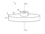
- FIG. 1 is a schematic perspective view of a shower plate according to the first embodiment.
- FIG. FIG. 2 is a schematic cross-sectional view of the shower plate according to the first embodiment.
- 3 is a schematic cross-sectional view taken along line III-III in FIG. 2.
- FIG. FIG. 4 is a schematic cross-sectional view of the vicinity of the cavity in the shower plate according to the second embodiment.
- FIG. 5 is a schematic cross-sectional view of the vicinity of the cavity in the shower plate according to the third embodiment.
- FIG. 6 is a schematic cross-sectional view of the vicinity of the cavity in the shower plate according to the fourth embodiment.
- FIG. 7 is a schematic cross-sectional view around a cavity in a shower plate according to a fifth embodiment.
- FIG. 8 is a schematic cross-sectional view of the vicinity of the cavity in the shower plate according to the sixth embodiment.
- FIG. 9 is a schematic cross-sectional view around a cavity in a shower plate according to the seventh embodiment.
- FIG. 10 is a schematic cross-sectional view of the vicinity of the cavity in the shower plate according to the eighth embodiment.
- FIG. 11 is a schematic cross-sectional view of the vicinity of the cavity in the shower plate according to the ninth embodiment.
- FIG. 12 is a schematic cross-sectional view of the vicinity of the cavity in the shower plate according to the tenth embodiment.
- FIG. 13 is a schematic cross-sectional view of a shower plate according to the eleventh embodiment.
- each embodiment can be appropriately combined within a range that does not contradict the processing content.
- the same parts are denoted by the same reference numerals, and overlapping descriptions are omitted.
- FIG. 1 is a schematic perspective view of a shower plate 1 according to the first embodiment.
- FIG. 2 is a schematic cross-sectional view of the shower plate 1 according to the first embodiment.
- 3 is a schematic cross-sectional view taken along line III-III in FIG. 2.
- FIG. 2 shows a schematic cross-sectional view taken along line II-II in FIG.
- a shower plate 1 according to the first embodiment shown in FIG. 1 ejects heated process gas (an example of fluid) onto a substrate such as a semiconductor wafer in, for example, a semiconductor manufacturing process.
- the shower plate 1 is mounted, for example, in a substrate processing apparatus that performs plasma processing or the like on substrates.
- the shower plate 1 has a base 10, a shaft 20, a resistance heating element 30, a channel 40, and an electrode 50.
- the direction from the base 10 to the shaft 20 is defined as the upward direction
- the direction from the shaft 20 to the base 10 is defined as the downward direction. good.
- the base 10 has a disk shape with a thickness in the vertical direction.
- the substrate 10 has an upper surface (an example of a first surface) 101 and a lower surface (an example of a second surface) 102 that are circular in plan view, and side surfaces 103 that are continuous with the upper surface 101 and the lower surface 102 .
- the upper surface 101 and the lower surface 102 of the substrate 10 are substantially parallel.
- the substrate 10 is made of ceramics, for example, and has insulating properties. Ceramics constituting the substrate 10 are, for example, aluminum nitride (AlN), aluminum oxide (Al 2 O 3 , alumina), yttrium oxide (Y 2 O 3 , yttria), silicon carbide (SiC), silicon nitride (Si 3 N 4 ), etc. as a main component.
- the main component is, for example, a material that accounts for 50% by mass or more or 80% by mass or more of the material.
- the shape of the substrate 10 is arbitrary.
- the substrate 10 has a disk shape, but it is not limited to this, and may have an elliptical plate shape, a rectangular plate shape, a trapezoidal plate shape, or the like.
- the shaft 20 is a member for introducing the process gas into the shower plate 1.
- the shaft 20 has, for example, a cylindrical shape.
- the shaft 20 has a through hole 21 passing through the shaft 20 from one end surface (here, the upper surface) to the other end surface (here, the bottom surface).
- Shaft 20 is connected to top surface 101 of base 10 .
- the shaft 20 is joined (bonded) to the upper surface 101 of the base 10 with an adhesive.
- the shaft 20 may be joined to the base 10 by solid phase joining.
- the material of shaft 20 is arbitrary. For example, as the material of the shaft 20, ceramics similar to the substrate 10 may be used.
- the resistance heating element 30 is located inside the base 10 along the upper surface 101 of the base 10 .
- the resistance heating element 30 is made of, for example, metals such as Ni, W, Mo and Pt, or alloys containing at least one of the above metals.
- the resistance heating element 30 extends along the upper surface 101 of the base 10.
- the resistance heating element 30 has, for example, a disc shape in a plan view with an opening formed in the center corresponding to the through hole 21 of the shaft 20 .
- the resistance heating element 30 generates heat by Joule heat generated by power supplied from a power supply unit (not shown).
- the resistance heating element 30 heats the channel 40 from the upper surface 101 side of the substrate 10 by generating heat. Thereby, the shower plate 1 can heat the process gas flowing through the flow path 40 .
- the channel 40 is located inside the base 10 .
- the channel 40 connects an inlet 111 positioned on the upper surface 101 of the base 10 and a plurality of outlets 121 positioned on the lower surface 102 of the base 10 .
- the introduction port 111 communicates with the through hole 21 of the shaft 20 .
- the channel 40 has an introduction channel 41 , an intermediate channel 42 and a plurality of outlet channels 43 .
- the introduction channel 41 communicates with the introduction port 111 and connects the introduction port 111 and the intermediate channel 42 .
- the introduction path 41 for example, extends from the introduction port 111 in the thickness direction of the base 10 and communicates with the intermediate flow path 42 .
- the intermediate flow path 42 is positioned between the resistance heating element 30 and the bottom surface 102 of the base 10 .
- the intermediate flow path 42 extends in the surface direction of the base 10 along the lower surface 102 of the base 10 .
- the plane direction of the substrate 10 is a direction substantially parallel to the upper surface 101 and the lower surface 102 of the substrate 10 .
- the intermediate flow path 42 may have a portion that is not positioned between the resistance heating element 30 and the lower surface 102 of the base 10 .
- the outlet channel 43 communicates with the intermediate channel 42 and connects the intermediate channel 42 and the outlet port 121 .
- the outlet path 43 for example, extends from the bottom surface of the intermediate flow path 42 in the thickness direction of the base 10 and communicates with the outlet port 121 .
- the flow path 40 is configured as described above, and guides the process gas that is introduced from the inlet 111 into the introduction path 41 through the through hole 21 of the shaft 20 and flows through the intermediate flow path 42 and the outlet path 43 . From outlet 121 , it can lead out below lower surface 102 of substrate 10 .
- the electrode 50 is located inside the base 10 between the intermediate channel 42 and the lower surface 102 of the base 10 .
- the electrode 50 is made of, for example, metals such as Ni, W, Mo and Pt, or alloys containing at least one of the above metals.
- the electrode 50 extends along the lower surface 102 of the substrate 10.
- the electrode 50 has, for example, a disc shape in plan view.
- the electrode 50 has a through hole corresponding to the position of the lead-out path 43 of the base 10 and having a larger diameter than the lead-out path 43 .
- the electrode 50 is an RF electrode capable of applying radio frequency (RF) power for generating plasma.
- RF radio frequency
- the substrate processing apparatus equipped with the shower plate 1 heats the flow path 40 inside the substrate 10 by the resistance heating element 30 when applying RF power to the electrode 50 to generate plasma.
- the flowing process gas is heated to a temperature suitable for plasma generation.
- the resistance heating elements 30 , the flow paths 40 and the electrodes 50 generally do not extend near the side surfaces 103 of the substrate 10 . This is because if the resistance heating element 30, the flow path 40, and the electrode 50 are extended to the vicinity of the side surface 103 of the substrate 10, delamination may occur in the substrate 10. FIG. Therefore, the resistance heating element 30, the flow path 40, and the electrode 50 are arranged with a certain distance from the side surface 103 of the substrate 10. As shown in FIG. In other words, the resistance heating element 30 , the flow path 40 and the electrodes 50 are smaller in diameter than the lower surface 102 of the substrate 10 .
- the heat in the flow path 40 heated by the resistance heating element 30 is not only transmitted to the process gas flowing through the flow path 40, but also transmitted from the flow path 40 to the outside of the substrate 10 in the plane direction, and finally to the side surface of the substrate 10. It is emitted from 103 into the external atmosphere.
- the heat of the intermediate flow path 42 which is the shortest distance from the side surface 103 of the base 10, tends to be transferred to the outer side of the base 10 in the plane direction. If the heat of the intermediate flow path 42 is transferred to the outside in the surface direction of the substrate 10, the temperature of the process gas flowing through the flow path 40 may be locally lowered and the temperature uniformity of the process gas may be deteriorated.
- a decrease in temperature uniformity of the process gas flowing through the flow path 40 is unfavorable because it causes solidification of the process gas within the flow path 40 .
- heat is transferred outward in the surface direction of the substrate 10 from the intermediate flow path 42 having the smallest distance from the side surface 103 of the substrate 10 in the flow path 40. It is desirable to suppress conduction.
- the shower plate 1 has a hollow portion 60 inside the base 10 .
- the hollow portion 60 is positioned adjacent to the intermediate channel 42 of the channel 40 in the surface direction of the base 10 .
- the hollow portion 60 is positioned adjacent to the intermediate flow path 42 with a partition wall 104 formed integrally with the base 10 interposed therebetween.
- a gas having a lower thermal conductivity than the ceramics forming the base 10 is accommodated inside the cavity 60 . Therefore, by positioning the hollow portion 60 adjacent to the intermediate flow path 42 of the flow path 40 in the surface direction of the base 10, heat conduction from the intermediate flow path 42 to the outside in the surface direction of the base 10 can be suppressed. . As a result, the temperature uniformity of the process gas flowing through the flow path 40 can be improved. As a result, it is possible to reduce the generation of solidified substances of the process gas in the flow path 40, and to reduce substrate defects caused by adhesion of the solidified substances to the substrate.
- the hollow portion 60 is positioned between the intermediate flow path 42 and the side surface 103 of the base 10 .
- the heat of the flow path 40 heated by the resistance heating element 30 is transferred to the outer side of the base 10 in the plane direction, and finally reaches the base 10. can be suppressed from being released into the external atmosphere from the side surface 103 of the .
- the gas contained in the cavity 60 contains at least nitrogen and argon and has a higher volume ratio of nitrogen and argon than air. good too.
- the gas accommodated in the cavity 60 may be a gas containing at least nitrogen and having a higher volume ratio of nitrogen than air.
- the inside of the hollow portion 60 may be in a vacuum state or may be in a decompressed state.
- a decompressed state means a state in which the pressure inside the cavity 60 is lower than the atmospheric pressure.
- the hollow portion 60 extends in an annular shape surrounding the outer periphery of the intermediate flow path 42 .
- the hollow portion 60 does not necessarily have to extend annularly.
- the hollow portion 60 may be divided into a plurality of arcuate spaces along the outer circumference of the intermediate flow path 42 and arranged.
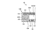
- FIG. 4 is a schematic cross-sectional view of the vicinity of the hollow portion 60 in the shower plate 1A according to the second embodiment.
- the substrate 10A has a resistance heating element 30A.
- the resistance heating element 30A extends to a position corresponding to the hollow portion 60 in the surface direction of the base 10A.
- the resistance heating element 30A By generating heat, the resistance heating element 30A not only heats the channel 40 (that is, the intermediate channel 42) from the upper surface 101 side of the substrate 10A, but also heats the cavity 60 adjacent to the intermediate channel 42. Can be heated.
- the resistance heating element 30A extends to a position corresponding to the hollow portion 60 in the plane direction of the substrate 10A, so that the temperature difference between the hollow portion 60 and the intermediate flow passage 42 can be reduced. It is possible to further suppress the heat conduction from the base 10A to the outside in the surface direction of the base 10A.
- FIG. 5 is a schematic cross-sectional view around a cavity 60B in a shower plate 1B according to the third embodiment.
- the base 10B has a hollow portion 60B.
- Cavity 60B has support 105 .
- the support 105 has an upper end positioned on the ceiling surface of the hollow portion 60B and a lower end positioned on the bottom surface of the hollow portion 60B.
- ceramics similar to the substrate 10 may be used.
- the hollow portion 60B having the support 105 facilitates transmission of heat generated in the resistance heating element 30A through the support 105 to the lower surface 102 of the base 10B.
- the temperature of the process gas led out from the outlet 121 to below the lower surface 102 of the substrate 10B can be maintained at a temperature suitable for plasma generation.
- the hollow portion 60B has the struts 105, the strength of the base 10B can be improved.
- FIG. 6 is a schematic cross-sectional view around a cavity 60B in a shower plate 1C according to the fourth embodiment.
- the substrate 10C has electrodes 50C.
- the electrode 50C extends to a position corresponding to the lower end of the support 105 in the surface direction of the base 10C.
- the electrode 50C extends in the surface direction of the substrate 10C to a position corresponding to the lower end of the column 105, heat generated in the resistance heating element 30A is promoted to be transmitted to the electrode 50C through the column 105. and the temperature of the electrode 50C can be appropriately adjusted.
- FIG. 7 is a schematic cross-sectional view of the vicinity of a hollow portion 60D in a shower plate 1D according to the fifth embodiment.
- a base 10D has a hollow portion 60D.
- Cavity 60D has support 105D.
- the strut 105D has a shape whose width widens toward the lower end of the strut 105D located on the bottom surface of the hollow portion 60D.
- a side surface of the support 105D is a tapered surface.
- the width of the column 105D of the hollow portion 60D widens as it approaches the lower end of the column 105D, thereby further promoting the transmission of the heat generated in the resistance heating element 30A to the lower surface 102 of the base 10D through the column 105D. be able to.
- FIG. 8 is a schematic cross-sectional view of the vicinity of a cavity 60E in a shower plate 1E according to the sixth embodiment.
- the base 10E has a hollow portion 60E.
- Cavity 60E has struts 105E.
- the support 105E has a shape whose width widens toward the lower end of the support 105E located on the bottom surface of the cavity 60E.
- the side surface of the support 105E is a stepped surface.
- the support 105E of the cavity 60E has a step surface on the side surface. Also in this case, the same effects as those of the shower plate 1D according to the fifth embodiment can be obtained. That is, the heat generated in the resistance heating element 30A can be further promoted to be transmitted to the lower surface 102 of the base 10E through the support 105E.
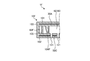
- FIG. 9 is a schematic cross-sectional view of the vicinity of the hollow portion 60B in the shower plate 1F according to the seventh embodiment.
- the base 10F has a hollow portion 60F.
- the hollow portion 60F is located adjacent to the intermediate flow path 42 with the partition wall 104F interposed therebetween.
- One wall surface of the partition wall 104F located on the cavity 60F side approaches the other wall surface located on the intermediate flow path 42 side as it moves away from the resistance heating element 30A.
- One wall surface of the partition wall 104F located on the cavity 60F side is a tapered surface.
- FIG. 10 is a schematic cross-sectional view of the vicinity of the cavity 60G in the shower plate 1G according to the eighth embodiment.
- the base 10G has a cavity 60G.
- the hollow portion 60G is located adjacent to the intermediate flow path 42 with the partition wall 104G interposed therebetween.
- One wall surface of the partition wall 104G located on the cavity 60G side approaches the other wall surface located on the intermediate flow path 42 side as it moves away from the resistance heating element 30A, similarly to the partition wall 104F in the seventh embodiment.
- One wall surface of the partition wall 104G located on the cavity 60G side is a stepped surface.
- one wall surface of the partition wall 104G located on the cavity 60G side is a stepped surface. Also in this case, the same effects as those of the shower plate 1F according to the seventh embodiment can be obtained. In other words, the heat generated in the resistance heating element 30A can be concentrated on the inner surface of the intermediate flow path 42 to suppress heat conduction from the intermediate flow path 42 to the outside in the surface direction of the substrate 10A.
- FIG. 11 is a schematic cross-sectional view of the vicinity of the cavity 60H in the shower plate 1H according to the ninth embodiment.
- the base 10H has a hollow portion 60H.
- the cavity portion 60H has a first cavity portion 61, a second cavity portion 62, and a third cavity portion 63.
- the first hollow portion 61 is a hollow portion positioned adjacent to the intermediate flow path 42 in the surface direction of the base 10H.
- the second hollow portion 62 is a hollow portion positioned adjacent to the resistance heating element 30A in the surface direction of the base 10H.
- the second cavity 62 communicates with the first cavity 61 .
- the third cavity 63 is a cavity located adjacent to the electrode 50C in the surface direction of the base 10H.
- the third cavity 63 communicates with the first cavity 61 .
- the cavity 60H may have the second cavity 62 positioned adjacent to the resistance heating element 30A in the plane direction of the substrate 10H.
- the cavity 60H may have the second cavity 62 positioned adjacent to the resistance heating element 30A in the plane direction of the substrate 10H.
- the cavity 60H may have a third cavity 63 positioned adjacent to the electrode 50C in the surface direction of the base 10H. According to such a configuration, it is possible to suppress heat conduction from the electrode 50C to the outside in the plane direction of the base 10H, in addition to heat conduction from the intermediate flow path 42 to the outside in the plane direction of the base 10H. Further, since the first hollow portion 61 and the third hollow portion 63 are in communication with each other, heat conduction from the electrode 50C to the outside in the plane direction of the base 10H can be further suppressed.
- FIG. 12 is a schematic cross-sectional view of the vicinity of the hollow portion 60B in the shower plate 1I according to the tenth embodiment.
- the base 10I in the shower plate 1I according to the tenth embodiment, the base 10I further has a cavity 70 in addition to the cavity 60B.
- the hollow portion 70 is positioned adjacent to each lead-out path 43 in the surface direction of the base 10I.
- the hollow portion 70 contains a gas having a lower thermal conductivity than the ceramics forming the base 10I.
- the gas contained in the cavity 70 may be the same gas as the gas contained in the cavity 60B.
- the hollow portion 70 extends annularly surrounding the outer periphery of each lead-out path 43 .
- the shower plate 1I may have a hollow portion 70 located adjacent to each lead-out path 43 in the surface direction of the base 10I inside the base 10I. According to such a configuration, in addition to heat conduction from the intermediate flow path 42 to the outside in the plane direction of the base 10I, it is possible to suppress heat conduction from the lead-out paths 43 to the outside in the plane direction of the base 10I. Heat uniformity of the process gas flowing through 40 can be further improved.
- FIG. 13 is a schematic cross-sectional view of a shower plate 1J according to the eleventh embodiment. 13, for the sake of convenience, the resistance heating element 30 and the electrodes 50 shown in FIG. 2 are omitted.
- the base 10J has a cavity 60J.
- the shaft 20 has a through hole 22 passing through the shaft 20 from one end surface (here, the upper surface) to the other end surface (here, the bottom surface).
- the hollow portion 60J is a channel through which a fluid other than the process gas flowing through the channel 40 flows.
- Other fluids that flow through the cavity 60J include, for example, inert gases such as N2, Ar, and He.
- the hollow portion 60J connects the inlet 112 positioned on the upper surface 101 of the base 10J and the plurality of outlets 122 positioned in the region surrounding the plurality of outlets 121 on the lower surface 102 of the base 10J. Specifically, the hollow portion 60J communicates with the introduction port 112 through the introduction path 65 and communicates with the outlet port 122 through the outlet path 66 . In addition, the introduction port 112 communicates with the through hole 22 of the shaft 20 .
- the hollow portion 60J is configured as described above.
- a fluid different from the process gas flowing through the flow path 40 was introduced into the introduction path 65 from the introduction port 112 through the through hole 22 of the shaft 20 and flowed through the cavity 60J and the discharge path 66. After that, it is led out from the lead-out port 122 to below the lower surface 102 of the base 10J.
- the hollow portion 60J may be a flow path through which a fluid other than the process gas flowing through the flow path 40 flows.
- a fluid other than the process gas flowing through the flow path 40 flows.
- the other fluid is led out from the outlet 122 to below the lower surface 102 of the substrate 10J, so that diffusion of the process gas led from the outlet 121 to below the lower surface 102 of the substrate 10 can be suppressed.
- the bases 10, 10A to 10J may be integrally formed instead of joining a plurality of members. According to such a configuration, it is not necessary to provide a bonding layer, for example, so reliability against thermal cycles can be enhanced.
- the columns supporting the ceilings of the cavities 60, 60B, 60D, 60E to 60H, and 60J are positioned inside the cavities 60, 60B, 60D, 60E to 60H, and 60J.
- Such a configuration can promote heat conduction in the thickness direction of the substrates 10, 10A to 10J.
- the partition walls 104, 104F, 104G separating the hollow portions 60, 60B, 60D, 60E to 60H, 60J and the intermediate flow path 42 in the substrates 10, 10A to 10J are located on the hollow portion side. You may have a recessed part in a wall surface. According to such a configuration, foreign matter in the process gas flowing through the flow path 40 can be retained within the recess.
- a method for manufacturing a shower plate according to the present disclosure will be described.
- a method for manufacturing the shower plate 1 according to the first embodiment will be described.
- the substrate and shaft are made separately. These members are then secured together.
- the base body and the shaft may be partially or wholly formed integrally.
- the method of manufacturing the shaft may be similar to various known methods, for example.
- a base is formed by laminating a plurality of ceramic green sheets. Specifically, a ceramic green sheet that forms the base, a metal sheet that forms the resistance heating element, and a metal sheet that forms the electrode are prepared. Here, a plurality of types of ceramic green sheets having different shapes are prepared in order to form the flow paths and the cavity. Then, the prepared sheets are laminated.
- the laminate of the ceramic green sheets and metal sheets is degreased and fired.
- the firing temperature is, for example, 1100° C. or higher and 1850° C. or lower.
- the gas contained in the firing atmosphere during firing is accommodated inside the hollow portion. This gas is different depending on the material of the ceramic green sheets to be prepared.
- the cavity is a closed space, by making the firing atmosphere vacuum during firing, gas is discharged from the communication holes of the ceramic green sheet generated during degreasing, and the cavity is brought into a vacuum state or a reduced pressure state.
- a metal paste or a wire may be used instead of the metal sheet.
- the shower plate (eg, shower plates 1, 1A to 1J) according to the embodiment includes a base (eg, base 10, 10A to 10J) and a resistance heating element (eg, resistance heating element 30, 30A). , a channel (eg, channel 40), and cavities (60, 60B, 60D, 60E to 60H, 60J).
- the substrate is a plate-shaped substrate made of ceramics.
- a resistive heating element is located inside the substrate along a first surface (eg, top surface 101) of the substrate.
- the flow path is a flow path located inside the substrate, located between the resistance heating element and the second surface (for example, the lower surface 102) opposite to the first surface of the substrate, and extending in the plane direction of the substrate.
- intermediate flow path 42 has an intermediate flow path (e.g., intermediate flow path 42) extending to the .
- the hollow portion is positioned adjacent to the intermediate flow path in the plane direction of the substrate inside the substrate.
- the cavity according to the embodiment may be located inside the base between the intermediate flow path and a side surface (for example, side surface 103) that is continuous with the first and second surfaces of the base.
- a side surface for example, side surface 103 that is continuous with the first and second surfaces of the base.
- the hollow portion according to the embodiment may extend annularly surrounding the outer circumference of the intermediate flow path in a cross-sectional view in the surface direction of the base.
- the cavity according to the embodiment may be positioned adjacent to the intermediate flow path with a partition wall (for example, partition walls 104, 104F, 104G) interposed therebetween.
- a partition wall for example, partition walls 104, 104F, 104G
- One wall surface of the partition wall located on the cavity side may approach the other wall surface located on the intermediate flow path side as the distance from the resistance heating element increases.
- one wall surface of the partition wall located on the cavity side may be a tapered surface or a stepped surface.
- the cavity according to the embodiment may have a support (for example, support 105, 105D, 105E) whose one end is located on the ceiling surface of the cavity and the other end is located on the bottom of the cavity.
- a support for example, support 105, 105D, 105E
- the temperature of the process gas led out below the lower surface of the substrate can be maintained at a temperature suitable for plasma generation.
- the support column according to the embodiment may have a shape that widens toward the other end located on the bottom surface of the hollow portion.
- the side surface of the support may be a tapered surface or a stepped surface.
- the shower plate according to the embodiment may further have electrodes (eg, electrodes 50 and 50C) positioned between the intermediate flow channel and the second surface of the substrate inside the substrate.
- the electrode may extend to a position corresponding to the other end of the support in the surface direction of the base.
- the resistance heating element according to the embodiment may extend in the surface direction of the base to a position corresponding to the cavity.
- the temperature difference between the hollow portion and the intermediate channel can be reduced, so that heat conduction from the intermediate channel to the outside in the surface direction of the base can be further suppressed.
- the cavity according to the embodiment includes a first cavity (for example, the first cavity 61) located adjacent to the intermediate flow path in the surface direction of the substrate, and a resistance heating element adjacent to the substrate in the surface direction.
- a second cavity e.g., second cavity 62
- first cavity and the second cavity according to the embodiment may communicate with each other.
- the shower plate of the embodiment it is possible to further suppress heat conduction from the resistance heating element to the outside in the surface direction of the base.
- the cavity according to the embodiment includes a first cavity positioned adjacent to the intermediate flow channel in the plane direction of the base and a third cavity (for example, a third cavity) positioned adjacent to the electrode in the plane direction of the base. 3 cavities 63).
- the first cavity and the third cavity according to the embodiment may communicate with each other.
- the shower plate of the embodiment it is possible to further suppress heat conduction from the electrode to the outside in the surface direction of the base.
- the channel according to the embodiment further includes a plurality of lead-out channels (eg lead-out channel 43) connecting the intermediate channel and a plurality of lead-out ports (eg lead-out port 121) located on the second surface of the substrate. may have.
- the shower plate according to the embodiment may further have other cavities (for example, cavity 70) located adjacent to the lead-out paths in the surface direction of the base inside the base.
- the cavity according to the embodiment may contain a gas having a lower thermal conductivity than the ceramics forming the base.
- the ceramics constituting the substrate according to the embodiment may be aluminum oxide or yttrium oxide.
- the gas accommodated in the cavity may be a gas containing at least nitrogen and argon and having a higher volume ratio of nitrogen and argon than air.
- the ceramics constituting the substrate may be aluminum nitride or silicon nitride.
- the gas accommodated in the hollow portion may be a gas containing at least nitrogen and having a higher volume ratio of nitrogen than air.
- the cavity according to the embodiment may be a channel through which a fluid other than the fluid (for example, process gas) that flows through the channel flows.
- the other fluid flowing through the cavity may be an inert gas. Therefore, according to the shower plate according to the embodiment, there is no need to provide a channel for another fluid separately from the channel for the process gas.
Landscapes
- Chemical & Material Sciences (AREA)
- General Chemical & Material Sciences (AREA)
- Chemical Kinetics & Catalysis (AREA)
- Engineering & Computer Science (AREA)
- Materials Engineering (AREA)
- Mechanical Engineering (AREA)
- Metallurgy (AREA)
- Organic Chemistry (AREA)
- Resistance Heating (AREA)
- Surface Heating Bodies (AREA)
Priority Applications (2)
| Application Number | Priority Date | Filing Date | Title |
|---|---|---|---|
| JP2023527875A JP7675814B2 (ja) | 2021-06-07 | 2022-06-07 | シャワープレート |
| US18/568,016 US12539520B2 (en) | 2021-06-07 | 2022-06-07 | Shower plate |
Applications Claiming Priority (2)
| Application Number | Priority Date | Filing Date | Title |
|---|---|---|---|
| JP2021-095171 | 2021-06-06 | ||
| JP2021095171 | 2021-06-07 |
Publications (1)
| Publication Number | Publication Date |
|---|---|
| WO2022260042A1 true WO2022260042A1 (ja) | 2022-12-15 |
Family
ID=84425074
Family Applications (1)
| Application Number | Title | Priority Date | Filing Date |
|---|---|---|---|
| PCT/JP2022/022978 Ceased WO2022260042A1 (ja) | 2021-06-07 | 2022-06-07 | シャワープレート |
Country Status (3)
| Country | Link |
|---|---|
| US (1) | US12539520B2 (https=) |
| JP (1) | JP7675814B2 (https=) |
| WO (1) | WO2022260042A1 (https=) |
Cited By (1)
| Publication number | Priority date | Publication date | Assignee | Title |
|---|---|---|---|---|
| WO2026029004A1 (ja) * | 2024-07-30 | 2026-02-05 | 京セラ株式会社 | 熱交換器 |
Families Citing this family (1)
| Publication number | Priority date | Publication date | Assignee | Title |
|---|---|---|---|---|
| KR102752082B1 (ko) * | 2023-12-12 | 2025-01-10 | 주식회사 미코세라믹스 | 퍼지 가스 유로를 구비하는 서셉터 |
Citations (8)
| Publication number | Priority date | Publication date | Assignee | Title |
|---|---|---|---|---|
| JPH0945624A (ja) * | 1995-07-27 | 1997-02-14 | Tokyo Electron Ltd | 枚葉式の熱処理装置 |
| JPH10168572A (ja) * | 1996-10-11 | 1998-06-23 | Ebara Corp | 反応ガス噴射ヘッド |
| JPH11302850A (ja) * | 1998-04-17 | 1999-11-02 | Ebara Corp | ガス噴射装置 |
| JP2004281648A (ja) * | 2003-03-14 | 2004-10-07 | Matsushita Electric Ind Co Ltd | 半導体装置の製造方法 |
| JP2007273747A (ja) * | 2006-03-31 | 2007-10-18 | Tokyo Electron Ltd | 基板処理装置および処理ガス吐出機構 |
| JP2010541239A (ja) * | 2007-09-25 | 2010-12-24 | ラム リサーチ コーポレーション | プラズマ処理装置のためのシャワーヘッド電極アセンブリ用温度制御モジュール |
| WO2019235282A1 (ja) * | 2018-06-07 | 2019-12-12 | 東京エレクトロン株式会社 | 基板処理装置およびシャワーヘッド |
| JP2019220639A (ja) * | 2018-06-22 | 2019-12-26 | 日本特殊陶業株式会社 | シャワーヘッド用ガス分配体 |
Family Cites Families (3)
| Publication number | Priority date | Publication date | Assignee | Title |
|---|---|---|---|---|
| US5900103A (en) * | 1994-04-20 | 1999-05-04 | Tokyo Electron Limited | Plasma treatment method and apparatus |
| KR100492258B1 (ko) | 1996-10-11 | 2005-09-02 | 가부시키가이샤 에바라 세이사꾸쇼 | 반응가스분출헤드 |
| KR102204026B1 (ko) | 2018-07-06 | 2021-01-18 | 주식회사 케이에스엠컴포넌트 | 세라믹 샤워 헤드 및 그를 구비한 화학 기상 증착 장치 |
-
2022
- 2022-06-07 WO PCT/JP2022/022978 patent/WO2022260042A1/ja not_active Ceased
- 2022-06-07 US US18/568,016 patent/US12539520B2/en active Active
- 2022-06-07 JP JP2023527875A patent/JP7675814B2/ja active Active
Patent Citations (8)
| Publication number | Priority date | Publication date | Assignee | Title |
|---|---|---|---|---|
| JPH0945624A (ja) * | 1995-07-27 | 1997-02-14 | Tokyo Electron Ltd | 枚葉式の熱処理装置 |
| JPH10168572A (ja) * | 1996-10-11 | 1998-06-23 | Ebara Corp | 反応ガス噴射ヘッド |
| JPH11302850A (ja) * | 1998-04-17 | 1999-11-02 | Ebara Corp | ガス噴射装置 |
| JP2004281648A (ja) * | 2003-03-14 | 2004-10-07 | Matsushita Electric Ind Co Ltd | 半導体装置の製造方法 |
| JP2007273747A (ja) * | 2006-03-31 | 2007-10-18 | Tokyo Electron Ltd | 基板処理装置および処理ガス吐出機構 |
| JP2010541239A (ja) * | 2007-09-25 | 2010-12-24 | ラム リサーチ コーポレーション | プラズマ処理装置のためのシャワーヘッド電極アセンブリ用温度制御モジュール |
| WO2019235282A1 (ja) * | 2018-06-07 | 2019-12-12 | 東京エレクトロン株式会社 | 基板処理装置およびシャワーヘッド |
| JP2019220639A (ja) * | 2018-06-22 | 2019-12-26 | 日本特殊陶業株式会社 | シャワーヘッド用ガス分配体 |
Cited By (1)
| Publication number | Priority date | Publication date | Assignee | Title |
|---|---|---|---|---|
| WO2026029004A1 (ja) * | 2024-07-30 | 2026-02-05 | 京セラ株式会社 | 熱交換器 |
Also Published As
| Publication number | Publication date |
|---|---|
| JP7675814B2 (ja) | 2025-05-13 |
| US12539520B2 (en) | 2026-02-03 |
| JPWO2022260042A1 (https=) | 2022-12-15 |
| US20240226922A9 (en) | 2024-07-11 |
| US20240131534A1 (en) | 2024-04-25 |
Similar Documents
| Publication | Publication Date | Title |
|---|---|---|
| JP7682966B2 (ja) | Umベース構成 | |
| EP1193751B1 (en) | Electrode and method of manufacturing an electrode | |
| WO2019082875A1 (ja) | 試料保持具 | |
| WO2022260042A1 (ja) | シャワープレート | |
| US12567567B2 (en) | Holding device | |
| WO2016143427A1 (ja) | 静電チャック装置 | |
| JP7632969B2 (ja) | 電極埋設部材、および基板保持部材 | |
| JP7483952B2 (ja) | ヒータ | |
| US11937345B2 (en) | Ceramic heater | |
| JP2006013256A (ja) | 静電チャック | |
| JP4590364B2 (ja) | 処理装置 | |
| JP2020035886A (ja) | 保持装置 | |
| US20250069943A1 (en) | Hybrid shaft assembly for thermal control in heated semiconductor pedestals | |
| JP4218899B2 (ja) | 静電チャックを備える基板ホルダ及びその製造方法 | |
| TW202447851A (zh) | 保持裝置 | |
| JP2025080405A (ja) | 保持装置 | |
| US12205839B2 (en) | Sample holder | |
| CN120981907A (zh) | 晶片载放台 | |
| JP6917180B2 (ja) | 加熱装置 | |
| JP2023040597A (ja) | セラミックスヒータ | |
| JP2005260251A (ja) | 載置台、プラズマ処理装置、および載置台の製造方法 | |
| US20260040883A1 (en) | Retention device | |
| WO2022215722A1 (ja) | シャワープレート |
Legal Events
| Date | Code | Title | Description |
|---|---|---|---|
| 121 | Ep: the epo has been informed by wipo that ep was designated in this application |
Ref document number: 22820221 Country of ref document: EP Kind code of ref document: A1 |
|
| WWE | Wipo information: entry into national phase |
Ref document number: 2023527875 Country of ref document: JP |
|
| WWE | Wipo information: entry into national phase |
Ref document number: 18568016 Country of ref document: US |
|
| NENP | Non-entry into the national phase |
Ref country code: DE |
|
| 122 | Ep: pct application non-entry in european phase |
Ref document number: 22820221 Country of ref document: EP Kind code of ref document: A1 |
|
| WWG | Wipo information: grant in national office |
Ref document number: 18568016 Country of ref document: US |