WO2022259831A1 - 脳波測定装置および脳波測定方法 - Google Patents
脳波測定装置および脳波測定方法 Download PDFInfo
- Publication number
- WO2022259831A1 WO2022259831A1 PCT/JP2022/020716 JP2022020716W WO2022259831A1 WO 2022259831 A1 WO2022259831 A1 WO 2022259831A1 JP 2022020716 W JP2022020716 W JP 2022020716W WO 2022259831 A1 WO2022259831 A1 WO 2022259831A1
- Authority
- WO
- WIPO (PCT)
- Prior art keywords
- band member
- ear
- group
- measurement device
- electroencephalogram measurement
- Prior art date
- Legal status (The legal status is an assumption and is not a legal conclusion. Google has not performed a legal analysis and makes no representation as to the accuracy of the status listed.)
- Ceased
Links
Images









Classifications
-
- A—HUMAN NECESSITIES
- A61—MEDICAL OR VETERINARY SCIENCE; HYGIENE
- A61B—DIAGNOSIS; SURGERY; IDENTIFICATION
- A61B5/00—Measuring for diagnostic purposes; Identification of persons
- A61B5/24—Detecting, measuring or recording bioelectric or biomagnetic signals of the body or parts thereof
- A61B5/25—Bioelectric electrodes therefor
- A61B5/251—Means for maintaining electrode contact with the body
- A61B5/256—Wearable electrodes, e.g. having straps or bands
-
- A—HUMAN NECESSITIES
- A61—MEDICAL OR VETERINARY SCIENCE; HYGIENE
- A61B—DIAGNOSIS; SURGERY; IDENTIFICATION
- A61B5/00—Measuring for diagnostic purposes; Identification of persons
- A61B5/24—Detecting, measuring or recording bioelectric or biomagnetic signals of the body or parts thereof
- A61B5/25—Bioelectric electrodes therefor
- A61B5/279—Bioelectric electrodes therefor specially adapted for particular uses
- A61B5/291—Bioelectric electrodes therefor specially adapted for particular uses for electroencephalography [EEG]
-
- A—HUMAN NECESSITIES
- A61—MEDICAL OR VETERINARY SCIENCE; HYGIENE
- A61B—DIAGNOSIS; SURGERY; IDENTIFICATION
- A61B5/00—Measuring for diagnostic purposes; Identification of persons
- A61B5/68—Arrangements of detecting, measuring or recording means, e.g. sensors, in relation to patient
- A61B5/6801—Arrangements of detecting, measuring or recording means, e.g. sensors, in relation to patient specially adapted to be attached to or worn on the body surface
- A61B5/6802—Sensor mounted on worn items
- A61B5/6803—Head-worn items, e.g. helmets, masks, headphones or goggles
-
- A—HUMAN NECESSITIES
- A61—MEDICAL OR VETERINARY SCIENCE; HYGIENE
- A61B—DIAGNOSIS; SURGERY; IDENTIFICATION
- A61B5/00—Measuring for diagnostic purposes; Identification of persons
- A61B5/68—Arrangements of detecting, measuring or recording means, e.g. sensors, in relation to patient
- A61B5/6801—Arrangements of detecting, measuring or recording means, e.g. sensors, in relation to patient specially adapted to be attached to or worn on the body surface
- A61B5/6813—Specially adapted to be attached to a specific body part
- A61B5/6814—Head
-
- A—HUMAN NECESSITIES
- A61—MEDICAL OR VETERINARY SCIENCE; HYGIENE
- A61B—DIAGNOSIS; SURGERY; IDENTIFICATION
- A61B5/00—Measuring for diagnostic purposes; Identification of persons
- A61B5/68—Arrangements of detecting, measuring or recording means, e.g. sensors, in relation to patient
- A61B5/6801—Arrangements of detecting, measuring or recording means, e.g. sensors, in relation to patient specially adapted to be attached to or worn on the body surface
- A61B5/683—Means for maintaining contact with the body
- A61B5/6831—Straps, bands or harnesses
-
- A—HUMAN NECESSITIES
- A61—MEDICAL OR VETERINARY SCIENCE; HYGIENE
- A61N—ELECTROTHERAPY; MAGNETOTHERAPY; RADIATION THERAPY; ULTRASOUND THERAPY
- A61N1/00—Electrotherapy; Circuits therefor
- A61N1/02—Details
- A61N1/04—Electrodes
- A61N1/0404—Electrodes for external use
- A61N1/0408—Use-related aspects
-
- A—HUMAN NECESSITIES
- A61—MEDICAL OR VETERINARY SCIENCE; HYGIENE
- A61B—DIAGNOSIS; SURGERY; IDENTIFICATION
- A61B2562/00—Details of sensors; Constructional details of sensor housings or probes; Accessories for sensors
- A61B2562/02—Details of sensors specially adapted for in-vivo measurements
- A61B2562/0209—Special features of electrodes classified in A61B5/24, A61B5/25, A61B5/283, A61B5/291, A61B5/296, A61B5/053
- A61B2562/0215—Silver or silver chloride containing
-
- A—HUMAN NECESSITIES
- A61—MEDICAL OR VETERINARY SCIENCE; HYGIENE
- A61B—DIAGNOSIS; SURGERY; IDENTIFICATION
- A61B2562/00—Details of sensors; Constructional details of sensor housings or probes; Accessories for sensors
- A61B2562/04—Arrangements of multiple sensors of the same type
- A61B2562/043—Arrangements of multiple sensors of the same type in a linear array
-
- A—HUMAN NECESSITIES
- A61—MEDICAL OR VETERINARY SCIENCE; HYGIENE
- A61B—DIAGNOSIS; SURGERY; IDENTIFICATION
- A61B2562/00—Details of sensors; Constructional details of sensor housings or probes; Accessories for sensors
- A61B2562/04—Arrangements of multiple sensors of the same type
- A61B2562/046—Arrangements of multiple sensors of the same type in a matrix array
-
- A—HUMAN NECESSITIES
- A61—MEDICAL OR VETERINARY SCIENCE; HYGIENE
- A61B—DIAGNOSIS; SURGERY; IDENTIFICATION
- A61B2562/00—Details of sensors; Constructional details of sensor housings or probes; Accessories for sensors
- A61B2562/12—Manufacturing methods specially adapted for producing sensors for in-vivo measurements
- A61B2562/125—Manufacturing methods specially adapted for producing sensors for in-vivo measurements characterised by the manufacture of electrodes
-
- A—HUMAN NECESSITIES
- A61—MEDICAL OR VETERINARY SCIENCE; HYGIENE
- A61B—DIAGNOSIS; SURGERY; IDENTIFICATION
- A61B2562/00—Details of sensors; Constructional details of sensor housings or probes; Accessories for sensors
- A61B2562/16—Details of sensor housings or probes; Details of structural supports for sensors
- A61B2562/164—Details of sensor housings or probes; Details of structural supports for sensors the sensor is mounted in or on a conformable substrate or carrier
-
- A—HUMAN NECESSITIES
- A61—MEDICAL OR VETERINARY SCIENCE; HYGIENE
- A61B—DIAGNOSIS; SURGERY; IDENTIFICATION
- A61B2562/00—Details of sensors; Constructional details of sensor housings or probes; Accessories for sensors
- A61B2562/22—Arrangements of medical sensors with cables or leads; Connectors or couplings specifically adapted for medical sensors
- A61B2562/221—Arrangements of sensors with cables or leads, e.g. cable harnesses
- A61B2562/222—Electrical cables or leads therefor, e.g. coaxial cables or ribbon cables
-
- A—HUMAN NECESSITIES
- A61—MEDICAL OR VETERINARY SCIENCE; HYGIENE
- A61B—DIAGNOSIS; SURGERY; IDENTIFICATION
- A61B5/00—Measuring for diagnostic purposes; Identification of persons
- A61B5/24—Detecting, measuring or recording bioelectric or biomagnetic signals of the body or parts thereof
- A61B5/25—Bioelectric electrodes therefor
- A61B5/263—Bioelectric electrodes therefor characterised by the electrode materials
- A61B5/265—Bioelectric electrodes therefor characterised by the electrode materials containing silver or silver chloride
-
- A—HUMAN NECESSITIES
- A61—MEDICAL OR VETERINARY SCIENCE; HYGIENE
- A61B—DIAGNOSIS; SURGERY; IDENTIFICATION
- A61B5/00—Measuring for diagnostic purposes; Identification of persons
- A61B5/24—Detecting, measuring or recording bioelectric or biomagnetic signals of the body or parts thereof
- A61B5/25—Bioelectric electrodes therefor
- A61B5/263—Bioelectric electrodes therefor characterised by the electrode materials
- A61B5/268—Bioelectric electrodes therefor characterised by the electrode materials containing conductive polymers, e.g. PEDOT:PSS polymers
Definitions
- the present invention relates to an electroencephalogram measurement device and an electroencephalogram measurement method.
- Patent Literature 1 has a comb row in which a plurality of conductive comb teeth are arranged, and penetrates between the hair of the subject to reach the scalp.
- the technique disclosed in U.S. Patent No. 5,300,000 includes a band worn on a person's head, a first strip adjustably coupled to the band, and a band for collecting a first set of signals from the head. includes a first set of electrodes coupled to the first strip and magnetic fasteners for coupling the first strip to the band.
- the present invention has been made in view of such circumstances, and aims to provide an electroencephalogram measurement device and an electroencephalogram measurement method that can be worn regardless of the shape of the wearer's head.
- a band member attached following the shape of the human head a plurality of electrode portions provided on one surface of the band member; a follow-up support unit that assists the band member in following the shape of the head; has The follow-up support unit an ear attachment part to be worn on a human ear; an attachment part to be attached to the band member;
- An electroencephalogram measurement device comprising: a connecting member that extends between the ear attachment portion and the attachment portion.
- an electroencephalogram measurement device and an electroencephalogram measurement method that can be worn regardless of the shape of the wearer's head.
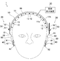
- FIG. 1 is a schematic diagram showing an electroencephalogram detection system in a state where an electroencephalogram measuring device is attached to a part according to an embodiment;
- FIG. 1 is a schematic diagram showing an electroencephalogram detection system with an electroencephalogram measuring device attached to the head according to an embodiment;
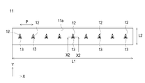
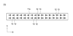
- FIG. 1 is a front view of an electroencephalogram detection electrode according to an embodiment;
- FIG. 1 is a plan view of an electroencephalogram detection electrode according to an embodiment;
- FIG. 4 is an enlarged view of a partial area X1 of FIG. 3 according to the embodiment;
- FIG. 5 is a cross-sectional view taken along line X2-X2 of FIG. 4 according to the embodiment;
- FIG. 5 is a diagram showing another example of the X2-X2 cross-sectional view of FIG.
- FIG. 10 is a plan view of another example (form 2) of the electroencephalogram detection electrode according to the embodiment;
- FIG. 11 is a plan view of another example (form 3) of the electroencephalogram detection electrode according to the embodiment;
- FIG. 10 is a plan view of another example (form 4) of the electroencephalogram detection electrode according to the embodiment;
- FIG. 11 is a plan view of another example (form 5) of the electroencephalogram detection electrode according to the embodiment;
- FIG. 11 is a plan view of another example (form 6) of the electroencephalogram detection electrode according to the embodiment;
- FIG. 11 is a plan view of another example (mode 7) of the electroencephalogram detection electrode according to the embodiment;
- FIG. 11 is a plan view of another example (Eighth Embodiment) of the electroencephalogram detection electrode according to the embodiment
- FIG. 12 is a plan view of another example (Mode 9) of the electroencephalogram detection electrode according to the embodiment
- FIG. 12 is a plan view of another example (Mode 10) of the electroencephalogram detection electrode according to the embodiment
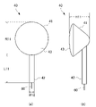
- It is a schematic diagram of the ear attachment part which concerns on embodiment. It is a figure which shows another example (form 2) of the ear-attachment part which concerns on embodiment. It is a figure which shows another example (form 3) of the ear-attachment part which concerns on embodiment. It is a figure which shows another example (form 4) of the ear-attachment part which concerns on embodiment. It is a figure which shows the attachment part which concerns on embodiment.
- FIG. 1 and 2 are schematic diagrams showing the electroencephalogram detection system 1 with the electroencephalogram measurement device 10 attached to the head 99 of a person.
- FIG. 1 is a front view of a person wearing the device.
- FIG. 2 is a side view of a person wearing the device.
- the electroencephalogram detection system 1 includes an electroencephalogram measurement device 10 and an electroencephalogram display device 20 .
- the electroencephalogram measurement device 10 is attached to a person's head 99 and detects electroencephalograms as potential fluctuations from the living body, and outputs the detected electroencephalograms to the electroencephalogram display device 20 .
- the electroencephalogram display device 20 acquires electroencephalograms detected by the electroencephalogram measurement device 10, displays them on a monitor, stores data, and performs well-known electroencephalogram analysis processing (measurement processing).
- the electroencephalogram measuring apparatus 10 includes a rubber-like elastic band member 11 that is attached so as to follow the shape of the human head 99, and a band member 11 that is suitable for the head 99. and a follow-up support unit 30 that assists to follow (follow).
- a plurality of elastic protrusions 12 integrally formed with the band member 11 are provided on one surface of the band member 11 (here, the band inner surface 11a on the head 99 side). At least the tip portion of the protrusion 12 constitutes an electrode portion 13 made of a conductive member.
- the tracking support parts 30 are provided at both ends of the band member 11 in the longitudinal direction.
- a connecting portion 60 (connecting member) provided across the portion 40 and the mounting portion 50 is provided.
- the electroencephalogram measurement device 10 is provided with connectors, electronic components, etc., and is connected to the electroencephalogram display device 20 .
- the electroencephalogram measurement device 10 and the electroencephalogram display device 20 may be configured integrally.
- the electroencephalogram display device 20 may be composed of a smart device (smart phone, tablet terminal) and a predetermined application functioning therewith. In this case, the electroencephalogram measurement device 10 has a communication function of wirelessly transmitting detected electroencephalograms.
- the electroencephalogram display device 20 has, for example, a control section, a storage section, a user IF, an output section, and an electroencephalogram processing data processing section. These include arithmetic units such as CPUs, memories such as ROMs and RAMs, storage devices such as HDDs and SSDs, monitors, communication IFs, etc., and are capable of using electroencephalograms obtained from the electroencephalogram measuring apparatus 10 according to a predetermined program. Convert to data format and perform well-known electroencephalogram analysis functions.
- FIG. 3 is a front view of the band member 11.
- FIG. 4 is a plan view of the band member 11.
- the band member 11 which was curved in FIG. 1, is shown in a flat state.
- the thickness direction of the band member 11 is the Z direction (the upward direction is +Z)
- the longitudinal direction of the rectangular shape is the X direction (the right direction is +X)
- the lateral direction is the Y direction. (The depth direction is +Y).
- the back side (+Y side) will be described as the front side
- the near side ( ⁇ Y side) as the rear side. 8 to 16 variations of the band member 11 will be described.
- the band member 11 described in FIGS. 10 will be described.
- the band member 11 is a plate-like body with a predetermined thickness t. Specifically, the band member 11 has a strip-like rectangular shape when viewed from above (plan view). A thickness t of the band member 11 is, for example, 0.1 mm to 30 mm.
- the longitudinal length L1 of the rectangular shape is, for example, 20 cm to 65 cm.
- the length L2 of the rectangular shape in the lateral direction is, for example, 0.5 cm to 5 cm.
- the shape of the band member 11 is not limited to a strip-like rectangular shape. For example, an elongated elliptical shape may be used instead of a rectangular shape.
- the thickness t of the band member 11 is not limited to a constant value, and the thickness may be partially thinned or thickened. In any case, the band member 11 follows the shape of the head 99 when the electroencephalogram measuring device 10 is worn on the head 99 .
- a plurality of projecting portions 12 are provided integrally with the band member 11 on one surface of the band member 11 (band inner surface 11a on the head 99 side).
- the plurality of protrusions 12 are arranged in a row at a predetermined pitch P when viewed from above.
- the pitch P of the protrusions 12 (that is, the electrode portions 13) is, for example, 1 mm to 20 mm.
- the pitch P is determined from the viewpoint of the number of electrode units 13 required for brain wave detection and the followability of the band member 11 to the head 99 .
- FIG. 5 is a diagram showing one protrusion 12 by enlarging the region X1 in the front view of FIG. 6 is a cross-sectional view taken along line X2-X2 in FIG. 4, and is also a cross-sectional view of the protrusion 12 in FIG.
- the protrusion 12 is formed integrally with the band member 11 so as to protrude from one surface of the band member 11 (in this case, the band inner surface 11a).
- An attachment portion 50 is attached to the surface on which the protrusion 12 is not provided (here, the band outer surface 11b).
- the height h1 of the triangular pyramid projection 12 is, for example, 0.5 mm to 20 mm, preferably 3 mm to 15 mm, and more preferably 4 mm to 10 mm.
- the protrusion 12 As a specific shape of the triangular pyramid that the protrusion 12 exhibits, for example, as shown in FIG. Yes, they are oriented.
- the vertices of the isosceles triangle are on one side (the front side (+Y side) in the drawing) in the short direction of the rectangular shape, and the base is on the other side (the rear side ( ⁇ Y side) in the drawing).
- the apex of the triangular pyramid that is, the tip of the protrusion 12
- the protruding portion 12 is oriented such that the front side (+Y side) is gentle and the rear side ( ⁇ Y side) is steep.
- the direction of the projection 12 means "the direction in which the vertices of the isosceles triangle face”.
- the protruding portion 12 is applied to the head 99 from the gentle side (+Y side), so that the subject does not feel discomfort (pain, etc.) and the hair is removed.
- the electroencephalogram measurement device 10 can be attached smoothly with little resistance from the outside.
- An electrode portion 13 made of a conductive member is provided at least at the tip of the protrusion 12 so as to cover the surface of the protrusion 12 .
- the electrode portion 13 is provided on the surface of the projection 12 within a predetermined height h2 from the apex of the triangular pyramid.
- the predetermined height h2 at which the electrode portion 13 is formed is, for example, 1 mm to 10 mm, depending on the height h1 of the projection portion 12.
- the conductive member of the electrode portion 13 is, for example, a paste containing a highly conductive metal.
- Good conductive metals include one or more selected from the group consisting of copper, silver, gold, nickel, tin, lead, zinc, bismuth, antimony, or alloys thereof.
- silver, silver chloride, and copper are suitable from the viewpoint of availability and conductivity.
- the electrode part 13 When forming the electrode part 13 with a paste containing a highly conductive metal, the top of the protrusion 12 made of a rubber-like elastic body is dipped (immersion coating) in a paste-like conductive solution containing a highly conductive metal. do. As a result, the electrode portion 13 is formed on the surface of the tip portion of the projection portion 12 .
- the electrode portion 13 as a conductive resin layer may be formed by applying a conductive solution containing a conductive filler and a solvent to the tip portion of the projection portion 12 .
- a conductive solution containing a conductive filler and a solvent to the tip portion of the projection portion 12 .
- the adhesion of the electrode portions 13 (conductive resin layer) can be enhanced.
- a conductive signal line 14 connected to the electrode portion 13 is provided inside the projection portion 12 .
- the material, thickness, and position of the signal line 14 are not particularly limited as long as the connected electroencephalogram display device 20 or the like can appropriately measure electroencephalograms.
- the electrode portion 13 is provided on the surface of the tip portion of the projection portion 12, for example, as shown in FIG. Line 14 is connected.
- the signal line 14 is electrically connected to the electrode portion 13 covering the tip of the protrusion 12 and is arranged inside the protrusion 12 from the tip toward the band member 11 .
- the signal line 14 can use a known one, and can be made of conductive fiber, for example.
- conductive fiber one or more selected from the group consisting of metal fiber, metal-coated fiber, carbon fiber, conductive polymer fiber, conductive polymer-coated fiber, and conductive paste-coated fiber can be used. These may be used alone or in combination of two or more.
- the metal material of the metal fibers and metal-coated fibers is not limited as long as it has conductivity, but copper, silver, gold, nickel, tin, lead, zinc, bismuth, antimony, stainless steel, aluminum, silver/chloride silver and alloys thereof; These may be used alone or in combination of two or more. Among these, silver can be used from the viewpoint of conductivity. Moreover, it is preferable that the metal material does not contain a metal such as chromium that causes a load on the environment.
- the fiber materials of the metal-coated fibers, conductive polymer-coated fibers, and conductive paste-coated fibers are not particularly limited, but may be synthetic fibers, semi-synthetic fibers, or natural fibers. Among these, it is preferable to use polyester, nylon, polyurethane, silk, cotton, and the like. These may be used alone or in combination of two or more.
- Examples of the carbon fibers include PAN-based carbon fibers and pitch-based carbon fibers.
- the conductive polymer material of the conductive polymer fiber and the conductive polymer-coated fiber is, for example, a mixture of a conductive polymer such as polythiophene, polypyrrole, polyaniline, polyacetylene, polyphenylene vinylene, polynaphthalene, and derivatives thereof and a binder resin, Alternatively, an aqueous solution of a conductive polymer such as PEDOT-PSS ((3,4-ethylenedioxythiophene)-poly(styrenesulfonic acid)) is used.
- PEDOT-PSS ((3,4-ethylenedioxythiophene)-poly(styrenesulfonic acid)
- the resin material contained in the conductive paste of the conductive paste-coated fiber is not particularly limited, but preferably has elasticity. It can contain one or more selected from the group consisting of propylene rubbers. These may be used alone or in combination of two or more.
- the conductive filler contained in the conductive paste of the conductive paste-coated fiber is not particularly limited, and known conductive materials may be used, such as metal particles, metal fibers, metal-coated fibers, carbon black, acetylene black, graphite, carbon It may contain one or more selected from the group consisting of fibers, carbon nanotubes, conductive polymers, conductive polymer-coated fibers and metal nanowires.
- the metal constituting the conductive filler is not particularly limited, but for example, copper, silver, gold, nickel, tin, lead, zinc, bismuth, antimony, silver/silver chloride, or at least one of these alloys. or, alternatively, two or more of these.
- silver or copper is preferable because of its high conductivity and high availability.
- the signal line 14 may be composed of twisted yarn obtained by twisting a plurality of linear conductive fibers. Thereby, disconnection of the signal line 14 at the time of deformation can be suppressed.
- the coating of the conductive fiber means not only covering the outer surface of the fiber material, but also, in the case of a twisted yarn obtained by twisting single fibers, a metal or a conductive polymer is added between the fibers in the twisted yarn. , or impregnated with a conductive paste to cover each single fiber constituting the twisted yarn.
- the tensile elongation at break of the signal line 14 is, for example, 1% to 50%, preferably 1.5% to 45%. By setting the value within such a numerical range, it is possible to suppress excessive deformation of the protrusion 12 while suppressing breakage during deformation.
- the signal line 14 can adopt various arrangement structures as long as it is a mode that conducts the inside of the protrusion 12 .
- the tip of the signal line 14 may be any of a protruding structure, a structure on substantially the same plane, and a buried structure with respect to the tip of the protrusion 12 or the inclined surface of the tip. From the viewpoint of connection stability with the electrode portion 13, a projecting structure may be used. A projecting portion at the tip of the signal line 14 is partially or entirely covered with the electrode portion 13 .
- the protruding structure of the tip of the signal line 14 may be unfolded, folded, or wrapped around the surface of the tip of the projection 12 . Also, the signal line 14 may not coincide with the vertical line extending from the tip (apex) of the protrusion 12 and may be inclined with respect to the vertical line.
- the signal line 14 is connected to the lower end of the electrode portion 13 (on the side of the band member 11), extends along the slope (surface) of the projection portion 12, and reaches a predetermined level. It may be in the form of being retracted into the protrusion 12 from the position.
- the end on the side connected to the electrode portion 13 and the end on the opposite side may be individually pulled out of the band member 11 .
- the plurality of signal lines 14 may be connected to a connector or the like provided on the band outer surface 11b of the band member 11 from inside the band member 11 and organized.
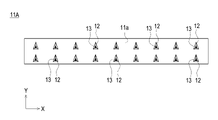
- FIG. 8 shows a plan view of the band member 11A of form 2.
- the difference from form 1 is mainly in the arrangement of the protrusions 12 . That is, in form 1, the plurality of protrusions 12 are arranged in a row in the same direction.
- a plurality of protrusions 12 are arranged in two rows. That is, it can be said that it is the structure which added one more line of the protrusion part 12 of the form 1.
- FIG. In other words, the plurality of protrusions 12 are arranged in a grid pattern (regular grid pattern).
- a plurality of projections 12 are arranged in a grid pattern (regular grid pattern). This makes it possible to realize the effects of the first form and to arrange the protrusions 12 (that is, the electrode parts 13) suitable for electroencephalogram detection. That is, stable electroencephalogram detection can be realized.
- FIG. 9 shows a plan view of the band member 11B of form 2.
- the difference from form 1 is mainly in the arrangement of the protrusions 12 . That is, in form 1, the plurality of protrusions 12 are arranged in a row in the same direction. On the other hand, in form 3, a plurality of protrusions 12 are arranged in two rows. However, unlike the band member 11A of form 2, the protrusions 12 are arranged alternately. In other words, the plurality of protrusions 12 are arranged in a houndstooth pattern.
- a plurality of protrusions 12 are arranged in a houndstooth pattern. This makes it possible to realize the effects of the first form and to arrange the protrusions 12 (that is, the electrode parts 13) suitable for electroencephalogram detection. That is, stable electroencephalogram detection can be realized.
- FIG. 10 shows a plan view of the band member 11C of form 4.
- the plurality of protrusions 12 are arranged in two rows, and the number (density) of the protrusions 12 in the front row (+Y side row) is reduced.
- the protrusions 12 in the row on the rear side ( ⁇ Y side row) in the drawing are arranged at a predetermined first pitch Pc1 .
- the protrusions 12 in the back row (+Y side) are arranged at a predetermined second pitch P c2 (for example, twice the first pitch P c1 ).
- P c2 for example, twice the first pitch P c1
- the band member 11C of this embodiment a plurality of protrusions 12 are alternately arranged with different densities. This makes it possible to realize the effects of the first form and to arrange the protrusions 12 (that is, the electrode parts 13) suitable for electroencephalogram detection. That is, stable electroencephalogram detection can be realized.
- the human head 99 has a common fixed shape.
- the position of the head 99 on which the electroencephalogram measurement device 10 (the band member 11C) is worn and the shape of the position of the head 99 touched when the device is worn have certain characteristics. The band member 11C can well follow such characteristics.
- FIG. 11 shows a plan view of a band member 11D of form 5.
- the band member 11D of this embodiment is the same as the first embodiment in that a plurality of protrusions 12 are arranged in a line, but the directions of the protrusions 12 are different. This makes it possible to appropriately correspond to the flow of hair.
- the projections 12 on the left half (eight on the left) in the figure are oriented rightward (that is, toward the center in the longitudinal direction of the band member 11), and the projections on the right half (eight on the right) in the figure 12 is oriented leftward (that is, oriented toward the center in the longitudinal direction of the band member 11D).
- the electroencephalogram measurement device 10 the band member 11D
- each protrusion 12 faces the top of the head 99. Therefore, the electroencephalogram measurement device 10 (band member 11D) can be worn while appropriately following the flow and amount of hair on the head 99 .
- the band member 11D is worn in a curved state from a flat state, the gentle side of the protrusion 12 comes into contact with the head 99, so discomfort can be avoided.
- FIG. 12 shows a plan view of the band member 11E of form 6.
- the band member 11E of this embodiment is the same as the embodiments 1 and 5 in that a plurality of protrusions 12 are arranged in a row, but the directions of the protrusions 12 are different. This makes it possible to appropriately correspond to the flow of hair.
- the projections 12 on the left half (eight on the left) in the illustration are oriented leftward (that is, toward the left end in the longitudinal direction of the band member 11), and on the right half (eight on the right) in the illustration.
- the projection 12 is oriented rightward (that is, oriented toward the right end in the longitudinal direction of the band member 11E).
- each protrusion 12 can be said to face downward (toward the position of the ear) from the top of the head 99.
- each protrusion 12 faces downward from the top of the head 99. . Therefore, the electroencephalogram measurement device 10 (band member 11E) can be worn while properly following the flow and amount of hair on the head 99 .
- the band member 11E is attached to the inner surface 11a of the band while being curved to some extent, the gentle side of the protrusion 12 comes into contact with the head 99, thereby avoiding discomfort.
- FIG. 13 shows a plan view of the band member 11F of form 7.
- two projections 12 facing each other are additionally provided at the longitudinal center of the band member 11F.
- the protrusion 12 on the front side (+Y side) in the illustration faces backward ( ⁇ Y direction), and the protrusion 12 on the rear side ( ⁇ Y side) in the illustration is forward (+Y direction). That is, there are provided two opposing protrusions 12 facing the center of the band member 11F (band inner surface 11a) (centers in the longitudinal direction and the lateral direction) when viewed from above.
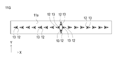
- FIG. 14 shows a plan view of the band member 11G of form 8.
- two projections 12 facing each other are additionally provided at the longitudinal center of the band member 11G. ing.
- the protrusion 12 on the front side (+Y side) in the illustration is forward (+Y direction)
- the protrusion 12 on the rear side ( ⁇ Y side) in the illustration is backward (-Y direction). That is, two projections 12 are provided at the center of the band member 11G (the inner surface 11a of the band) (centers in the longitudinal direction and the lateral direction) when viewed from above.
- the band member 11G of this embodiment With the band member 11G of this embodiment, the same effect as the band member 11E of the sixth embodiment can be obtained. Furthermore, the addition of the above-described two back-facing protrusions 12 improves the wearability of the electroencephalogram measurement device 10 (band member 11G) on the head 99, especially the function of the protrusions 12 to penetrate and stabilize the hair. can be improved.
- the band member 11H of this form With the band member 11H of this form, the same effect as the band member 11D of form 5 can be obtained. Furthermore, by arranging the plurality of protrusions 12 in two rows, one on the front side and the other on the back side, the same effect as the band member 11B of form 2, that is, the placement of the protrusions 12 (that is, the electrode parts 13) suitable for electroencephalogram detection is possible, and stable electroencephalogram detection can be realized.
- the rows of the plurality of projecting portions 12 of the band member 11E of form 6 are arranged in front and rear two rows.
- the features of the second and sixth modes are combined.
- the projections 12 of the left half are oriented leftward (that is, toward the left end in the longitudinal direction of the band member 11E) and rightward in the illustration.
- the orientation of half is to the right (that is, to the right end in the longitudinal direction of the band member 11E).
- the same effect as the band member 11E of the fifth embodiment can be obtained. Furthermore, by arranging the plurality of protrusions 12 in two rows, one on the front side and the other on the back side, the same effect as the band member 11B of form 2, that is, the placement of the protrusions 12 (that is, the electrode parts 13) suitable for electroencephalogram detection is possible, and stable electroencephalogram detection can be realized.
- Embodiments 1 to 10 a triangular pyramid was exemplified as the shape of the protrusion 12, but other pyramids such as cones and square pyramids, and truncated pyramids obtained by removing the top of the pyramid may be used. .
- the band member 11 and the protrusion 12 are rubber-like elastic bodies, more specifically, rubber or thermoplastic elastomer (also simply referred to as “elastomer (TPE)").
- rubber include silicone rubber.
- thermoplastic elastomers include styrene-based TPE (TPS), olefin-based TPE (TPO), vinyl chloride-based TPE (TPVC), urethane-based TPE (TPU), ester-based TPE (TPEE), and amide-based TPE (TPAE).
- the band member 11 and projections 12 of the electroencephalogram measurement device 10 are made of silicone rubber, the surface of the band member 11 (band inner surface 11a and band outer surface 11b) measured at 37°C in accordance with JIS K 6253 (1997).
- Rubber hardness A is, for example, 15 or more and 55 or less.
- the silicone rubber-based curable composition will be described.
- the silicone rubber can be composed of a cured product of a silicone rubber-based curable composition.
- the curing step of the silicone rubber-based curable resin composition is, for example, heating at 100 to 250° C. for 1 to 30 minutes (primary curing), followed by post-baking (secondary curing) at 100 to 200° C. for 1 to 4 hours. It is done by
- An insulating silicone rubber is a silicone rubber that does not contain a conductive filler
- a conductive silicone rubber is a silicone rubber that contains a conductive filler
- the silicone rubber-based curable composition according to this embodiment can contain a vinyl group-containing organopolysiloxane (A).
- the vinyl group-containing organopolysiloxane (A) is a polymer that is the main component of the silicone rubber-based curable composition of the present embodiment.
- the insulating silicone rubber-based curable composition and the conductive silicone rubber-based curable composition may contain the same vinyl group-containing linear organopolysiloxane.
- the vinyl group-containing linear organopolysiloxane of the same kind includes at least the same vinyl group with the same functional group and has a linear shape. can be different.
- the insulating silicone rubber-based curable composition and the conductive silicone rubber-based curable composition may further contain different vinyl group-containing organopolysiloxanes.
- the vinyl group-containing organopolysiloxane (A) can contain a vinyl group-containing linear organopolysiloxane (A1) having a linear structure.
- the vinyl group-containing linear organopolysiloxane (A1) has a linear structure and contains vinyl groups, and the vinyl groups serve as cross-linking points during curing.
- the vinyl group content of the vinyl group-containing linear organopolysiloxane (A1) is not particularly limited, but for example, it preferably has two or more vinyl groups in the molecule and is 15 mol % or less. , 0.01 to 12 mol %.
- the amount of vinyl groups in the vinyl group-containing linear organopolysiloxane (A1) is optimized, and a network can be reliably formed with each component described later.
- " ⁇ " means including both numerical values.
- the vinyl group content is the mol % of the vinyl group-containing siloxane units when the total units constituting the vinyl group-containing linear organopolysiloxane (A1) are taken as 100 mol %. .
- one vinyl group is considered to be one vinyl group-containing siloxane unit.
- the degree of polymerization of the vinyl group-containing linear organopolysiloxane (A1) is not particularly limited, it is, for example, preferably in the range of about 1,000 to 10,000, more preferably in the range of about 2,000 to 5,000.
- the degree of polymerization can be determined, for example, as a polystyrene-equivalent number-average polymerization degree (or number-average molecular weight) in GPC (gel permeation chromatography) using chloroform as a developing solvent.
- the specific gravity of the vinyl group-containing linear organopolysiloxane (A1) is not particularly limited, but is preferably in the range of about 0.9 to 1.1.
- the heat resistance, flame retardancy, chemical stability, etc. of the resulting silicone rubber can be improved by using those having the degree of polymerization and specific gravity within the ranges described above. can be improved.
- vinyl group-containing linear organopolysiloxane (A1) those having a structure represented by the following formula (1) are particularly preferable.
- R 1 is a substituted or unsubstituted alkyl group, alkenyl group, aryl group, or a hydrocarbon group of a combination thereof having 1 to 10 carbon atoms.
- the alkyl group having 1 to 10 carbon atoms includes, for example, methyl group, ethyl group, propyl group, etc. Among them, methyl group is preferable.
- the alkenyl group having 1 to 10 carbon atoms includes, for example, vinyl group, allyl group, butenyl group, etc. Among them, vinyl group is preferred.
- the aryl group having 1 to 10 carbon atoms includes, for example, a phenyl group.
- R 2 is a substituted or unsubstituted alkyl group, alkenyl group, aryl group having 1 to 10 carbon atoms, or a hydrocarbon group combining these.
- the alkyl group having 1 to 10 carbon atoms includes, for example, methyl group, ethyl group, propyl group, etc. Among them, methyl group is preferable.
- alkenyl groups having 1 to 10 carbon atoms include vinyl groups, allyl groups and butenyl groups.
- the aryl group having 1 to 10 carbon atoms include a phenyl group.
- R 3 is a substituted or unsubstituted alkyl group having 1 to 8 carbon atoms, an aryl group, or a hydrocarbon group combining these.
- the alkyl group having 1 to 8 carbon atoms includes, for example, methyl group, ethyl group, propyl group, etc. Among them, methyl group is preferred.
- Examples of the aryl group having 1 to 8 carbon atoms include a phenyl group.
- examples of substituents for R 1 and R 2 in formula (1) include methyl group and vinyl group, and examples of substituents for R 3 include methyl group.
- a plurality of R 1 are independent of each other and may be different or the same. Furthermore, the same applies to R 2 and R 3 .
- m and n are the numbers of repeating units constituting the vinyl group-containing linear organopolysiloxane (A1) represented by formula (1), m is an integer of 0 to 2000, and n is 1000 to 10000. is an integer of m is preferably 0-1000 and n is preferably 2000-5000.
- vinyl group-containing linear organopolysiloxane (A1) represented by formula (1) include, for example, those represented by the following formula (1-1).
- R 1 and R 2 are each independently a methyl group or a vinyl group, and at least one is a vinyl group.
- the vinyl group-containing linear organopolysiloxane (A1) a first vinyl group-containing vinyl group having a vinyl group content of 2 or more vinyl groups in the molecule and not more than 0.4 mol% It contains a linear organopolysiloxane (A1-1) and a second vinyl group-containing linear organopolysiloxane (A1-2) having a vinyl group content of 0.5 to 15 mol%. It is preferable to have As crude rubber, which is a raw material of silicone rubber, a first vinyl group-containing linear organopolysiloxane (A1-1) having a general vinyl group content and a second vinyl group-containing linear organopolysiloxane having a high vinyl group content were used.
- the vinyl groups can be unevenly distributed, and the crosslink density can be more effectively formed in the crosslink network of the silicone rubber. As a result, the tear strength of silicone rubber can be increased more effectively.
- the vinyl group-containing linear organopolysiloxane (A1) for example, a unit in which R 1 is a vinyl group and/or a unit in which R 2 is a vinyl group in the above formula (1-1) , a first vinyl group-containing linear organopolysiloxane (A1-1) having 2 or more in the molecule and containing 0.4 mol% or less, and a unit in which R 1 is a vinyl group and / or R It is preferable to use a second vinyl group-containing linear organopolysiloxane (A1-2) containing 0.5 to 15 mol % of units in which 2 is a vinyl group.
- the first vinyl group-containing linear organopolysiloxane (A1-1) preferably has a vinyl group content of 0.01 to 0.2 mol %.
- the second vinyl group-containing linear organopolysiloxane (A1-2) preferably has a vinyl group content of 0.8 to 12 mol %.
- (A1-1) and (A1-2) are not particularly limited, but for example, the weight ratio of (A1-1):(A1-2) is preferably 50:50 to 95:5, and 80:20 to 90: 10 is more preferred.
- the first and second vinyl group-containing linear organopolysiloxanes (A1-1) and (A1-2) may be used singly or in combination of two or more. good.
- the vinyl group-containing organopolysiloxane (A) may also contain a vinyl group-containing branched organopolysiloxane (A2) having a branched structure.
- the silicone rubber-based curable composition of the present embodiment may contain a cross-linking agent.
- Cross-linking agents can include organohydrogenpolysiloxanes (B).
- Organohydrogenpolysiloxane (B) is classified into linear organohydrogenpolysiloxane (B1) having a linear structure and branched organohydrogenpolysiloxane (B2) having a branched structure. Either or both may be included.
- the insulating silicone rubber-based curable composition and the conductive silicone rubber-based curable composition may contain the same type of cross-linking agent.
- the same type of cross-linking agent should have at least a common structure such as a linear structure or a branched structure, and may contain different molecular weight distributions and different functional groups in the molecule, and the amount added may be different.
- the insulating silicone rubber-based curable composition and the conductive silicone rubber-based curable composition may further contain different cross-linking agents.
- the linear organohydrogenpolysiloxane (B1) has a linear structure and a structure ( ⁇ Si—H) in which hydrogen is directly bonded to Si, and is the vinyl group-containing organopolysiloxane (A). It is a polymer that undergoes a hydrosilylation reaction with other vinyl groups and other vinyl groups contained in other components of the silicone rubber-based curable composition to crosslink these components.
- the molecular weight of the linear organohydrogenpolysiloxane (B1) is not particularly limited, for example, the weight average molecular weight is preferably 20,000 or less, more preferably 1,000 or more and 10,000 or less.
- the weight average molecular weight of the linear organohydrogenpolysiloxane (B1) can be measured, for example, by polystyrene conversion in GPC (gel permeation chromatography) using chloroform as a developing solvent.
- the linear organohydrogenpolysiloxane (B1) does not have a vinyl group. Thereby, it is possible to accurately prevent the progress of the cross-linking reaction in the molecule of the linear organohydrogenpolysiloxane (B1).
- linear organohydrogenpolysiloxane (B1) for example, one having a structure represented by the following formula (2) is preferably used.
- R 4 is a substituted or unsubstituted alkyl group, alkenyl group, aryl group having 1 to 10 carbon atoms, a hydrocarbon group combining these groups, or a hydride group.
- the alkyl group having 1 to 10 carbon atoms includes, for example, methyl group, ethyl group, propyl group, etc. Among them, methyl group is preferable.
- alkenyl groups having 1 to 10 carbon atoms include vinyl groups, allyl groups and butenyl groups.
- the aryl group having 1 to 10 carbon atoms include a phenyl group.
- R 5 is a substituted or unsubstituted alkyl group, alkenyl group, aryl group having 1 to 10 carbon atoms, a hydrocarbon group combining these, or a hydride group.
- alkyl group having 1 to 10 carbon atoms include methyl group, ethyl group and propyl group, with methyl group being preferred.
- alkenyl groups having 1 to 10 carbon atoms include vinyl groups, allyl groups and butenyl groups.
- Examples of the aryl group having 1 to 10 carbon atoms include a phenyl group.
- a plurality of R 4 are independent of each other and may be different from each other or may be the same. The same is true for R5. However, at least two or more of the plurality of R 4 and R 5 are hydride groups.
- R 6 is a substituted or unsubstituted alkyl group having 1 to 8 carbon atoms, an aryl group, or a hydrocarbon group combining these.
- the alkyl group having 1 to 8 carbon atoms includes, for example, methyl group, ethyl group, propyl group, etc. Among them, methyl group is preferred.
- Examples of the aryl group having 1 to 8 carbon atoms include a phenyl group.
- a plurality of R 6 are independent from each other and may be different from each other or may be the same.
- substituents for R 4 , R 5 and R 6 in formula (2) include methyl group and vinyl group, and methyl group is preferred from the viewpoint of preventing intramolecular cross-linking reaction.
- m and n are the numbers of repeating units constituting the linear organohydrogenpolysiloxane (B1) represented by formula (2), m is an integer of 2 to 150, and n is an integer of 2 to 150. is.
- m is an integer from 2-100 and n is an integer from 2-100.
- the straight-chain organohydrogenpolysiloxane (B1) may be used alone or in combination of two or more.
- the branched organohydrogenpolysiloxane (B2) has a branched structure, it is a component that forms regions with a high crosslink density and greatly contributes to the formation of a loose and dense structure of crosslink density in the silicone rubber system. Further, like the linear organohydrogenpolysiloxane (B1), it has a structure ( ⁇ Si—H) in which hydrogen is directly bonded to Si, and in addition to the vinyl group of the vinyl group-containing organopolysiloxane (A), silicone It is a polymer that undergoes a hydrosilylation reaction with the vinyl groups of the components blended in the rubber-based curable composition to crosslink these components.
- the specific gravity of the branched organohydrogenpolysiloxane (B2) is in the range of 0.9 to 0.95.
- the branched organohydrogenpolysiloxane (B2) does not have a vinyl group. Thereby, it is possible to accurately prevent the progress of the cross-linking reaction in the molecule of the branched organohydrogenpolysiloxane (B2).
- branched organohydrogenpolysiloxane (B2) one represented by the following average compositional formula (c) is preferable.
- R 7 is a monovalent organic group, a is an integer ranging from 1 to 3, m is the number of H a (R 7 ) 3-a SiO 1/2 units, n is SiO 4/ is a number of 2 units)
- R 7 is a monovalent organic group, preferably a substituted or unsubstituted alkyl group having 1 to 10 carbon atoms, an aryl group, or a hydrocarbon group combining these.
- the alkyl group having 1 to 10 carbon atoms includes, for example, methyl group, ethyl group, propyl group, etc. Among them, methyl group is preferred.
- Examples of the aryl group having 1 to 10 carbon atoms include a phenyl group.
- a is the number of hydride groups (hydrogen atoms directly bonded to Si) and is an integer in the range of 1 to 3, preferably 1.
- m is the number of H a (R 7 ) 3-a SiO 1/2 units
- n is the number of SiO 4/2 units.
- the branched organohydrogenpolysiloxane (B2) has a branched structure.
- the linear organohydrogenpolysiloxane (B1) and the branched organohydrogenpolysiloxane (B2) differ in that their structures are linear or branched.
- the number of bound alkyl groups R (R/Si) is 1.8 to 2.1 for the linear organohydrogenpolysiloxane (B1) and 0.8 to 1 for the branched organohydrogenpolysiloxane (B2). .7 range.
- the branched organohydrogenpolysiloxane (B2) has a branched structure, for example, when heated to 1000° C. at a heating rate of 10° C./min in a nitrogen atmosphere, the residual amount is 5% or more. becomes.
- the straight-chain organohydrogenpolysiloxane (B1) is straight-chain, the amount of residue after heating under the above conditions is almost zero.
- branched organohydrogenpolysiloxane (B2) include those having a structure represented by the following formula (3).
- R 7 is a substituted or unsubstituted alkyl group having 1 to 8 carbon atoms, an aryl group, a hydrocarbon group combining these, or a hydrogen atom.
- the alkyl group having 1 to 8 carbon atoms includes, for example, methyl group, ethyl group, propyl group, etc. Among them, methyl group is preferable.
- Examples of the aryl group having 1 to 8 carbon atoms include a phenyl group.
- the substituent of R7 include a methyl group and the like.
- a plurality of R 7 are independent of each other and may be different from each other or may be the same.
- the branched organohydrogenpolysiloxane (B2) may be used alone or in combination of two or more.
- the amount of hydrogen atoms (hydride groups) directly bonded to Si is not particularly limited.
- linear organohydrogenpolysiloxane (B1) and branched organohydrogenpolysiloxane are The total amount of hydride groups in the siloxane (B2) is preferably from 0.5 to 5 mol, more preferably from 1 to 3.5 mol.
- the silicone rubber-based curable composition according to this embodiment contains a non-conductive filler.
- the non-conductive filler may contain silica particles (C) as needed. Thereby, the hardness and mechanical strength of the elastomer can be improved.
- the insulating silicone rubber-based curable composition and the conductive silicone rubber-based curable composition may contain the same type of non-conductive filler.
- Non-conductive fillers of the same type may have at least common constituent materials, and may differ in particle size, specific surface area, surface treatment agent, or addition amount thereof.
- the insulating silicone rubber-based curable composition and the conductive silicone rubber-based curable composition may further contain different silane coupling agents.
- the silica particles (C) are not particularly limited, but for example, fumed silica, calcined silica, precipitated silica, etc. are used. These may be used alone or in combination of two or more.
- the silica particles (C) preferably have a BET specific surface area of, for example, 50 to 400 m 2 /g, more preferably 100 to 400 m 2 /g. Also, the average primary particle size of the silica particles (C) is, for example, preferably 1 to 100 nm, more preferably about 5 to 20 nm.
- silica particles (C) having a specific surface area and an average particle size within the above ranges, the hardness and mechanical strength of the formed silicone rubber can be improved, especially the tensile strength can be improved.
- the silicone rubber-based curable composition of the present embodiment can contain a silane coupling agent (D).
- Silane coupling agent (D) can have a hydrolyzable group. The hydrolyzable group is hydrolyzed with water to form a hydroxyl group, and the hydroxyl group undergoes a dehydration condensation reaction with the hydroxyl group on the surface of the silica particle (C), thereby modifying the surface of the silica particle (C).
- the insulating silicone rubber-based curable composition and the conductive silicone rubber-based curable composition may contain the same type of silane coupling agent.
- the silane coupling agents of the same kind should have at least a common functional group, and may differ in other functional groups in the molecule and in the amount added.
- the insulating silicone rubber-based curable composition and the conductive silicone rubber-based curable composition may further contain different silane coupling agents.
- this silane coupling agent (D) can contain a silane coupling agent having a hydrophobic group.
- the hydrophobic group is imparted to the surface of the silica particles (C), so that the cohesive force of the silica particles (C) in the silicone rubber-based curable composition and further in the silicone rubber is reduced (hydrogen aggregation due to bonding is reduced), and as a result, it is presumed that the dispersibility of the silica particles (C) in the silicone rubber-based curable composition is improved. This increases the interface between the silica particles (C) and the rubber matrix, increasing the reinforcing effect of the silica particles (C).
- the slipperiness of the silica particles (C) within the matrix is improved when the rubber matrix is deformed.
- the improved dispersibility and slipperiness of the silica particles (C) improve the mechanical strength (for example, tensile strength and tear strength) of the silicone rubber due to the silica particles (C).
- the silane coupling agent (D) can contain a silane coupling agent having a vinyl group.
- vinyl groups are introduced onto the surfaces of the silica particles (C). Therefore, during curing of the silicone rubber-based curable composition, that is, a hydrosilylation reaction occurs between the vinyl group of the vinyl group-containing organopolysiloxane (A) and the hydride group of the organohydrogenpolysiloxane (B). , When a network (crosslinked structure) is formed by these, the vinyl groups possessed by the silica particles (C) also participate in the hydrosilylation reaction with the hydride groups possessed by the organohydrogenpolysiloxane (B). Silica particles (C) also come to be taken in. As a result, it is possible to reduce the hardness and increase the modulus of the formed silicone rubber.
- silane coupling agent (D) a silane coupling agent having a hydrophobic group and a silane coupling agent having a vinyl group can be used in combination.
- silane coupling agent (D) examples include those represented by the following formula (4).
- n represents an integer of 1-3.
- Y represents a functional group having a hydrophobic group, a hydrophilic group or a vinyl group, and when n is 1 it is a hydrophobic group, and when n is 2 or 3 at least one of It is a hydrophobic group.
- X represents a hydrolyzable group.
- the hydrophobic group is an alkyl group having 1 to 6 carbon atoms, an aryl group, or a hydrocarbon group having a combination thereof, and examples thereof include a methyl group, an ethyl group, a propyl group, a phenyl group, and the like. Methyl groups are preferred.
- the hydrophilic group includes, for example, a hydroxyl group, a sulfonic acid group, a carboxyl group, a carbonyl group, etc. Among them, a hydroxyl group is particularly preferable.
- the hydrophilic group may be contained as a functional group, but is preferably not contained from the viewpoint of imparting hydrophobicity to the silane coupling agent (D).
- the hydrolyzable group includes an alkoxy group such as a methoxy group and an ethoxy group, a chloro group, a silazane group, and the like.
- a silazane group is preferable because of its high reactivity with the silica particles (C).
- a compound having a silazane group as a hydrolyzable group has two structures of (Y n —Si—) in the above formula (4) due to its structural characteristics.
- silane coupling agent (D) represented by the above formula (4) are as follows.
- Those having a hydrophobic group as the functional group include, for example, methyltrimethoxysilane, dimethyldimethoxysilane, phenyltrimethoxysilane, methyltriethoxysilane, dimethyldiethoxysilane, phenyltriethoxysilane, n-propyltrimethoxysilane, alkoxysilanes such as n-propyltriethoxysilane, hexyltrimethoxysilane, hexyltriethoxysilane, decyltrimethoxysilane; chlorosilanes such as methyltrichlorosilane, dimethyldichlorosilane, trimethylchlorosilane, phenyltrichlorosilane; hexamethyldisilazane.
- silane coupling agent having a trimethylsilyl group containing one or more selected from the group consisting of hexamethyldisilazane, trimethylchlorosilane, trimethylmethoxysilane, and trimethylethoxysilane is preferred.
- Examples of those having a vinyl group as the functional group include methacryloxypropyltriethoxysilane, methacryloxypropyltrimethoxysilane, methacryloxypropylmethyldiethoxysilane, methacryloxypropylmethyldimethoxysilane, vinyltriethoxysilane, and vinyltrimethoxysilane.
- alkoxysilanes such as silane and vinylmethyldimethoxysilane
- chlorosilanes such as vinyltrichlorosilane and vinylmethyldichlorosilane
- divinyltetramethyldisilazane divinyltetramethyldisilazane.
- a silane coupling agent having a vinyl group-containing organosilyl group containing one or more selected from the group consisting of methyldimethoxysilane is preferred.
- silane coupling agent (D) contains two kinds of a silane coupling agent having a trimethylsilyl group and a silane coupling agent having a vinyl group-containing organosilyl group
- those having a hydrophobic group include hexamethyldisilazane, Divinyltetramethyldisilazane is preferably included as one having a vinyl group.
- the ratio of (D1) and (D2) is not particularly limited, but for example, (D1):(D2) in a weight ratio of 1:0.001 to 1:0.35, preferably 1:0.01 to 1:0.20, more preferably 1:0.03 to 1:0 .15. Desired physical properties of the silicone rubber can be obtained by setting it to such a numerical range. Specifically, the dispersibility of silica in the rubber and the crosslinkability of the rubber can be balanced.
- the lower limit of the content of the silane coupling agent (D) is preferably 1% by mass or more with respect to 100 parts by weight of the total amount of the vinyl group-containing organopolysiloxane (A). It is more preferably at least 5% by mass, even more preferably at least 5% by mass.
- the upper limit of the content of the silane coupling agent (D) is preferably 100% by mass or less, and 80% by mass or less, with respect to 100 parts by weight of the total amount of the vinyl group-containing organopolysiloxane (A). It is more preferable that the content is 40% by mass or less.
- the silicone rubber can have appropriate mechanical properties.
- the silicone rubber-based curable composition according to this embodiment may contain a catalyst.
- the catalyst may contain platinum or a platinum compound (E).
- Platinum or a platinum compound (E) is a catalytic component that acts as a catalyst during curing.
- the amount of platinum or platinum compound (E) added is a catalytic amount.
- the insulating silicone rubber-based curable composition and the conductive silicone rubber-based curable composition may contain the same type of catalyst. Catalysts of the same kind may have at least common constituent materials, and the catalysts may contain different compositions and may differ in addition amount.
- the insulating silicone rubber-based curable composition and the conductive silicone rubber-based curable composition may further contain different catalysts.
- platinum or platinum compound (E) a known one can be used, for example, platinum black, platinum supported on silica or carbon black, chloroplatinic acid or an alcohol solution of chloroplatinic acid, A complex salt of platinic acid and olefin, a complex salt of chloroplatinic acid and vinyl siloxane, and the like are included.
- the platinum or platinum compound (E) may be used alone or in combination of two or more.
- the content of platinum or platinum compound (E) in the silicone rubber-based curable composition means the amount of catalyst, and can be set as appropriate.
- (A), silica particles (C), the total amount of 100 parts by weight of the silane coupling agent (D), platinum group metal is an amount of 0.01 to 1000 ppm by weight unit, preferably 0. The amount is 1 to 500 ppm.
- the silicone rubber-based curable composition according to the present embodiment may contain water (F) in addition to the above components (A) to (E).
- Water (F) is a component that functions as a dispersion medium for dispersing each component contained in the silicone rubber-based curable composition and contributes to the reaction between the silica particles (C) and the silane coupling agent (D). . Therefore, the silica particles (C) and the silane coupling agent (D) can be linked to each other more reliably in the silicone rubber, and uniform properties can be exhibited as a whole.
- the silicone rubber-based curable composition of the present embodiment may further contain other components in addition to the above components (A) to (F).
- Other components include silica particles (C) such as diatomaceous earth, iron oxide, zinc oxide, titanium oxide, barium oxide, magnesium oxide, cerium oxide, calcium carbonate, magnesium carbonate, zinc carbonate, glass wool, and mica.
- additives such as inorganic fillers, reaction inhibitors, dispersants, pigments, dyes, antistatic agents, antioxidants, flame retardants, and thermal conductivity improvers.
- the conductive solution (conductive silicone rubber composition) according to the present embodiment contains the conductive filler and solvent in addition to the silicone rubber-based curable composition containing no conductive filler.
- solvents can be used as the solvent, and for example, a high boiling point solvent can be included. These may be used alone or in combination of two or more.
- solvents examples include aliphatic hydrocarbons such as pentane, hexane, cyclohexane, heptane, methylcyclohexane, ethylcyclohexane, octane, decane, dodecane, and tetradecane; benzene, toluene, ethylbenzene, xylene, trifluoromethylbenzene; , aromatic hydrocarbons such as benzotrifluoride; diethyl ether, diisopropyl ether, dibutyl ether, cyclopentyl methyl ether, cyclopentyl ethyl ether, ethylene glycol dimethyl ether, ethylene glycol diethyl ether, diethylene glycol dimethyl ether, 1,4-dioxane, 1,3 - ethers such as dioxane and tetrahydrofuran; haloalkanes such as
- the conductive solution can have a viscosity suitable for various coating methods such as spray coating and dip coating.
- the lower limit of the content of the silica particles (C) contained in the electrode portion 13 is the amount of the silica particles (C) and the conductive filler. For example, it is 1% by mass or more, preferably 3% by mass or more, and more preferably 5% by mass or more, relative to the total amount of 100% by mass. Thereby, the mechanical strength of the electrode portion 13 can be improved.
- the upper limit of the content of the silica particles (C) contained in the electrode portion 13 is, for example, 20% by mass or less with respect to the total amount of 100% by mass of the silica particles (C) and the conductive filler, It is preferably 15% by mass or less, more preferably 10% by mass or less. Thereby, it is possible to achieve a balance between conductivity, mechanical strength, and flexibility in the electrode portion 13 .
- a conductive silicone rubber can be obtained by heating and drying the conductive solution as necessary.
- the conductive silicone rubber may be configured without silicone oil. As a result, it is possible to suppress a decrease in conductivity due to bleeding out of the silicone oil onto the surface of the electrode portion 13 .
- the band member 11 and the plurality of protrusions 12 are seamlessly joined by molding a curable elastomer composition such as a silicone rubber-based curable composition. you get a body As a result, the electroencephalogram measurement device 10 that is excellent in flexibility (that is, flexibility that can follow the head 99 ) and strength and that can follow the head 99 well can be realized.
- the rubber hardness A ie flexibility, can be controlled by appropriately selecting the type and amount of each component contained in the silicone rubber curable composition, the preparation method of the silicone rubber curable composition, and the like.
- An example of the method for manufacturing the band member 11 can include the following steps. First, using a mold, the silicone rubber-based curable composition is molded under heat and pressure to obtain a molded body comprising the band member 11 and the protrusions 12 . Subsequently, the signal wire 14 was passed through the interior of each columnar portion of the molded body obtained using a sewing needle. A pasty conductive solution is dip-coated on the surface (predetermined height h2) of the tip portion of the protruding portion 12 of the molded body obtained thereafter, and post-curing is performed after heating and drying. Thereby, the electrode portion 13 can be formed on the surface of the projection portion 12 . As described above, the band member 11 can be manufactured. During the molding process, insert molding may be used in which the silicone rubber-based curable composition is introduced into the molding space in which the signal line 14 is arranged, and pressurized and heat-molded.
- the following support section 30 has an ear attachment section 40 , an attachment section 50 and a connection section 60 .
- the ear-worn part 40 is worn on a human ear 80 .
- the attachment portion 50 is attached to the band member 11 .
- the connecting portion 60 is a wire having one end 61 attached to the attachment portion 50 and the other end 62 attached to the ear attachment portion 40 , and is passed between the ear attachment portion 40 and the attachment portion 50 .
- FIG. 17 shows the ear-mounted part 40.
- FIG. 17(a) is a plan view of the ear-mounted part 40
- FIG. 17(b) is a side view.
- the ear attachment part 40 has, for example, a shape similar to that of a so-called open-ear type earphone, and is attached so as to fit into the concha auricular cavity 81 .
- the ear attachment part 40 may be provided with a member that fits from the attachment part main body 41 into the ear canal like a canal-type earphone.
- the ear attachment part 40 has an attachment part main body 41 to be attached to the concha 81, and an extension part 42 extending from the attachment part main body 41 through the intertragic notch 84 and extending out of the ear 80 (outer ear). .
- the attachment portion main body 41 and the extension portion 42 are formed of a hard member such as polyamide resin, for example. I wish I had. Further, the mounting portion main body 41 and the extending portion 42 do not need to be entirely made of the same material. For example, the portion of the mounting portion main body 41 that contacts the conchal cavity 81 may be made of a rubber member.
- the mounting portion main body 41 has a substantially conical shape, and a portion corresponding to the bottom surface of the cone forms a slightly convex (hemispherical) curved surface.
- the size of the mounting portion main body 41 is not particularly limited as long as it can be worn in the conchal cavity 81, but considering individual differences in the shape of the conchae 81, many people can wear it smoothly. It is sufficient that the attachment state can be maintained without being unexpectedly removed after attachment.
- the size of the ear attachment part 40 (the attachment part main body 41 and the extension part 42) may be prepared not only in one size but also in a plurality of sizes, and may be configured to be replaceable.
- the diameter R11 of the conical bottom surface of the mounting portion main body 41 can be in the range of 16 to 27 mm, for example. Also, the height H11 of the cone can be set to 8 to 20 mm.
- the extending portion 42 has a cylindrical shape and extends from the conical side surface of the mounting portion main body 41 .
- the extension position can be, for example, the apex side of the 1/2 of the cone in the height direction.
- One end portion 62 of the connecting portion 60 is attached to the extending end portion 42 a of the extending portion 42 .
- the extending portion 42 may have any size as long as it extends from the mounting portion main body 41 fitted in the conchaal cavity 81 to the outside or near the outside of the ear 80 (outer ear) via the intertragic notch 84 .
- the cylindrical diameter R12 of the extending portion 42 can be, for example, 3 to 15 mm.
- the length L11 of the portion located outside the mounting portion main body 41 in a top view can be set to, for example, 10 to 50 mm.
- ABS resin polypropylene
- polyethylene polyethylene
- FIG. 18 shows a perspective view of another form of the ear attachment part 40A.
- An ear-mounted portion 40A is a modification of the ear-mounted portion 40 shown in FIG. 41 A of attachment part main bodies have the communication hole 48 which communicates the inside and outside of the concha of the ear in the state which was mounted
- the attachment portion main body 41A is attached to the concha 81, external sounds are not blocked, and smooth communication can be performed between the subject who performs electroencephalogram measurement and the operator of the device or the like.
- FIG. 19 shows another form of the ear attachment part 40B.
- the ear attachment part 40B has a configuration that sandwiches the helix 82 and the earlobe 85 of the ear 80 (outer ear).
- the ear attachment part 40B has a clip-type mechanism with a spring, and biases the front surface part 40B1, the opposite back surface part 40B2, and the helix 82 disposed therebetween in a direction to sandwich them. and a spring 40B3 (torsion spring).
- a magnet-type mechanism, a screw-type mechanism, or the like may be used.
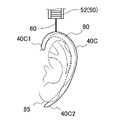
- FIG. 20 shows an ear-mounted part 40C of yet another form.
- the ear attachment part 40C has a shape to be hung on the ear 80 (outer ear), here a substantially C shape.
- one end 40C1 of the ear-mounted part 40C is hooked above the helix 82 and curved along the auricle-temporal groove on the back side (head 99 side). has a curved shape reaching the ear lobe 85 .
- one end portion 61 of the connecting portion 60 connected to the plate-like member 52 is attached to the uppermost portion (that is, the band member 11 side) when the ear attachment portion 40C is worn.
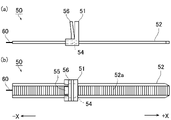
- the mounting portion 50 is shown in FIG. FIG. 21(a) is a side view, and FIG. 20(b) is a plan view.
- the attachment portions 50 are attached to both longitudinal ends of the band outer surface 11 b of the band member 11 .
- the attachment portion 50 functions as a fixing portion that attaches the tracking support portion 30 to the band member 11 and also functions as an adjustment portion that adjusts the attachment state of the band member 11 to the head portion 99 .
- the mounting portion 50 has a long band-shaped plate-like member 52 and a locking portion 51 that locks the plate-like member 52 at a desired position.
- a plurality of teeth 52a are arranged in rows on one main surface of the plate-like member 52, the ends of which extend in the transverse direction.
- One end of a wire-like connecting portion 60 is attached to one end of the plate-like member 52 .
- the locking part 51 has a passage 54 through which the plate member 52 can be inserted, and is attached to the band outer surface 11 b of the band member 11 .
- the passage 54 has a pawl 55 and a releasing portion 56 .
- the pawl 55 does not mesh with the teeth 52a when moving the plate-like member 52 in the direction of inserting it into the passage 54 (here, leftward), and moves the plate-like member 52 in the direction of pulling it out of the passage 54 (here, rightward).
- a pawl 55 is sometimes arranged which meshes with the tooth 52a.
- the releasing portion 56 is interlocked with the claw 55, and by operating the releasing portion 56, the engagement between the claw 55 and the tooth 52a can be released, and the plate-like member 52 can be moved in either the left or right direction. That is, according to the attachment portion 50, the distance to the ear attachment portion 40 attached to the plate member 52 via the connection portion 60 can be adjusted, and as a result, the wearing state of the band member 11 can be adjusted.
- Various plastics can be used as the material of the mounting portion 50, although there is no particular limitation. From the viewpoint of physical properties, processability, cost, etc., 66 nylon can be preferably used.
- a hook-and-loop fastener mechanism As examples of the mounting portion 50, a hook-and-loop fastener mechanism, a cam buckle mechanism, a buckle mechanism, a button mechanism, or the like can be adopted.
- a hook-and-loop fastener mechanism a part of a band-shaped hook-and-loop fastener is attached to the band member 11, and the surfaces are joined by bending it.
- a ring-shaped portion of the end portion of the connecting portion 60 is attached to the bent portion.
- the connecting portion 60 is composed of a solid wire member, one end of which is attached to the ear attachment portion 40 (extending portion 42) and the other end of which is attached to the plate member 52 of the attaching portion 50. ing.
- the material of the connecting portion 60 is not particularly limited, various plastics such as polyvinyl chloride and polyethylene can be used.
- the connecting portion 60 may be composed of a non-stretchable resin member, or may be composed of a stretchable elastic member (rubber-like member).
- a method of wearing the tracking support unit 30 is, for example, as follows. First, for one mounting portion 50 of the two mounting portions 50, with the plate member 52 removed from the lock portion 51 or fully extended, the mounting portion main body 41 of the ear mounting portion 40 is inserted into the concha cavity. It is fixed by fitting into 81 (S10). Subsequently, the connecting portion 60, which is a wire rod, is laid along the back of the ear 80 (S11). Next, the plate-like member 52 is inserted into the locking portion 51 while preventing the connecting portion 60 from coming off the aligned position, and the length of the plate-like member 52 protruding from the locking portion 51 is adjusted and temporarily fixed. (S12).
- the mounting portion main body 41 is attached to the other mounting portion 50 by the same procedure (S10 to S12), and the length of the plate-like member 52 protruding from the lock portion 51 is adjusted and temporarily fixed (S13). After both mounting portions 50 are temporarily fixed, the length of the plate-like member 52 protruding from the lock portion 51 is finely adjusted to adjust the tightness of the band member 11 by the follow-up support portion 30 (S14). After adjustment (S14), electroencephalogram measurement is started.
- the electroencephalogram measurement device 10 includes a band member 11 that is worn following the shape of the human head 99, a plurality of electrode portions 13 provided on one surface of the band member 11; a follow-up support unit 30 that assists in following the shape of the head 99 of the band member 11; has The follow-up support unit 30 an ear attachment part 40 to be attached to a human ear 80 (outer ear); an attachment part 50 attached to the band member 11; A connecting portion 60 (connecting member) provided across the ear attachment portion 40 and the mounting portion 50 is provided.
- the electroencephalogram measurement device 10 can be worn regardless of the shape of the wearer's head 99 .
- the tracking support unit 30 has an adjusting unit that adjusts the state of following the shape of the head 99 .
- the adjustment section has a mechanism for adjusting the length between the ear attachment section 40 and the attachment section 50 .
- the mounting portion 50 (the plate-like member 52 and the lock portion 51) functions as an adjusting portion, so that an appropriate follow-up state, that is, an electroencephalogram measurement environment can be established regardless of the shape and size of the wearer's head 99. realizable.
- the adjustment section has a plate member 52 and a lock section 51 that locks it at a predetermined position. By inserting the plate-like member 52 into the passage 54 of the locking portion 51 and engaging the teeth 52a of the plate-like member 52 with the claws 55, both fine adjustment and appropriate fixation can be achieved.
- the connecting portion 60 has an elastic member.
- connection portion 60 By using an elastic member such as a rubber wire for the connection portion 60 that connects the attachment portion 50 and the ear attachment portion 40, the length can be adjusted and the contact state of the band member 11 (projection portion 12) with the head portion 99 can be adjusted. can be adjusted in a well-balanced manner.
- the ear fitting part 40 is worn by being fitted into the concha of the ear (that is, the concha of the ear 81).
- the ear attachment part 40 has a communication hole 48 that communicates between the inside and the outside of the concha of the ear when attached to the concha of the ear (that is, the concha of the ear 81).
- the ear attachment part 40 is attached by sandwiching the outer ear.
- the ear attachment part 40 is worn by hanging it on the outer ear.
- the band member 11 is composed of a rubber-like elastic body. Since the band member 11 is a rubber-like elastic body, it follows the shape of the human head 99 . As a result, the electroencephalogram measurement device 10 can be worn regardless of the shape of the person's head 99 .
- (11) having a plurality of elastic protrusions 12 integrally provided with the band member 11;
- the electrode portion 13 is provided on the projection portion 12 .
- the pressure during mounting can be dispersed. Furthermore, since it has the flexibility to follow the shape of the head 99 when worn, pressure is not concentrated on a specific projection 12 (electrode 13), thus avoiding discomfort to the person. can. In other words, it is possible to avoid affecting the measurement result by feeling uncomfortable.
- the band member 11 is elastic and flexible, the electrode portion 13 of the protrusion 12 contacts the head portion 99 in an appropriate direction and with an appropriate pressure. From this point of view as well, electroencephalogram detection can be stabilized. (12)
- the electrode portion 13 has a conductive member provided at least at the tip portion of the projection portion 12 . (13)
- the above-described electroencephalogram measurement device 10 is attached to the subject's head 99 to measure electroencephalograms.
- electroencephalogram detection system 10 electroencephalogram detection electrodes 11, 11A, 11B, 11C, 11D, 11E, 11F, 11G, 11H, 11I band member 11a band inner surface 11b band outer surface 12 protrusion 13 electrode portion 14 signal line 20 electroencephalogram display device 30 Tracking support parts 40, 40A, 40B, 40C Ear attachment part 41 Attachment part main body 42 Extension part 50 Mounting part 51 Lock part 52 Plate member 52a Tooth 54 Passage 55 Claw 60 Connection part
Landscapes
- Health & Medical Sciences (AREA)
- Life Sciences & Earth Sciences (AREA)
- Animal Behavior & Ethology (AREA)
- Veterinary Medicine (AREA)
- Public Health (AREA)
- Engineering & Computer Science (AREA)
- Biomedical Technology (AREA)
- General Health & Medical Sciences (AREA)
- Pathology (AREA)
- Molecular Biology (AREA)
- Surgery (AREA)
- Medical Informatics (AREA)
- Heart & Thoracic Surgery (AREA)
- Physics & Mathematics (AREA)
- Biophysics (AREA)
- Nuclear Medicine, Radiotherapy & Molecular Imaging (AREA)
- Radiology & Medical Imaging (AREA)
- Measurement And Recording Of Electrical Phenomena And Electrical Characteristics Of The Living Body (AREA)
Priority Applications (4)
| Application Number | Priority Date | Filing Date | Title |
|---|---|---|---|
| EP22820013.5A EP4353154A4 (en) | 2021-06-07 | 2022-05-18 | Brain wave measuring device and brain wave measuring method |
| US18/562,859 US20240225510A1 (en) | 2021-06-07 | 2022-05-18 | Brain wave measuring device and brain wave measuring method |
| JP2022563483A JP7468695B2 (ja) | 2021-06-07 | 2022-05-18 | 脳波測定装置および脳波測定方法 |
| JP2023212871A JP2024020664A (ja) | 2021-06-07 | 2023-12-18 | 脳波測定装置および脳波測定方法 |
Applications Claiming Priority (2)
| Application Number | Priority Date | Filing Date | Title |
|---|---|---|---|
| JP2021094959 | 2021-06-07 | ||
| JP2021-094959 | 2021-06-07 |
Publications (1)
| Publication Number | Publication Date |
|---|---|
| WO2022259831A1 true WO2022259831A1 (ja) | 2022-12-15 |
Family
ID=84424821
Family Applications (1)
| Application Number | Title | Priority Date | Filing Date |
|---|---|---|---|
| PCT/JP2022/020716 Ceased WO2022259831A1 (ja) | 2021-06-07 | 2022-05-18 | 脳波測定装置および脳波測定方法 |
Country Status (4)
| Country | Link |
|---|---|
| US (1) | US20240225510A1 (https=) |
| EP (1) | EP4353154A4 (https=) |
| JP (2) | JP7468695B2 (https=) |
| WO (1) | WO2022259831A1 (https=) |
Cited By (4)
| Publication number | Priority date | Publication date | Assignee | Title |
|---|---|---|---|---|
| JPWO2024232203A1 (https=) * | 2023-05-09 | 2024-11-14 | ||
| WO2025084148A1 (ja) * | 2023-10-20 | 2025-04-24 | 住友ベークライト株式会社 | 脳波測定装置および脳波測定方法 |
| WO2025134597A1 (ja) * | 2023-12-19 | 2025-06-26 | 住友ベークライト株式会社 | 脳波測定装置および脳波測定方法 |
| WO2025164548A1 (ja) * | 2024-02-01 | 2025-08-07 | 住友ベークライト株式会社 | 脳波測定用電極 |
Families Citing this family (2)
| Publication number | Priority date | Publication date | Assignee | Title |
|---|---|---|---|---|
| EP4470466A4 (en) * | 2022-01-26 | 2025-09-17 | Sumitomo Bakelite Co | FLEXIBLE SHEET ELECTRODE, WEARABLE BIOELECTRODE AND BIOSENSOR |
| WO2023145565A1 (ja) * | 2022-01-26 | 2023-08-03 | 住友ベークライト株式会社 | 柔軟性シート電極、ウェアラブル生体電極および生体センサ |
Citations (6)
| Publication number | Priority date | Publication date | Assignee | Title |
|---|---|---|---|---|
| CN205697764U (zh) * | 2016-01-22 | 2016-11-23 | 周常安 | 眼镜式脑部活动传感器以及眼镜式电生理活动感测装置 |
| US20160367189A1 (en) * | 2014-01-06 | 2016-12-22 | Interaxon Inc. | Wearable apparatus for brain sensors |
| JP2018094434A (ja) | 2013-03-14 | 2018-06-21 | ザ ニールセン カンパニー (ユー エス) エルエルシー | 脳波データを収集し解析するためのシステムおよび方法 |
| JP2018175287A (ja) | 2017-04-11 | 2018-11-15 | ニッタ株式会社 | 脳波測定用電極及びその製造方法 |
| US20190223747A1 (en) * | 2016-01-22 | 2019-07-25 | Chang-An Chou | Wearable physiological activity sensor, sensing device, and sensing system |
| JP2021094959A (ja) | 2019-12-16 | 2021-06-24 | 住友ゴム工業株式会社 | タイヤ |
Family Cites Families (6)
| Publication number | Priority date | Publication date | Assignee | Title |
|---|---|---|---|---|
| JP5589593B2 (ja) | 2009-06-29 | 2014-09-17 | ソニー株式会社 | 生体信号測定用装具 |
| US8989836B2 (en) * | 2013-03-08 | 2015-03-24 | Brainscope Company, Inc. | Electrode array and method of placement |
| WO2016080804A1 (en) * | 2014-11-20 | 2016-05-26 | Samsung Electronics Co., Ltd. | Apparatus for measuring bioelectrical signals |
| JP6675535B2 (ja) | 2015-09-30 | 2020-04-01 | 東海光学株式会社 | 脳活動検出システム、脳活動検出システムを使用した脳活動の解析方法、そのような脳活動の解析方法による個人特性の評価方法及び個人の見え方の評価方法 |
| KR102353644B1 (ko) * | 2017-06-30 | 2022-01-21 | 주식회사 브레인유 | 마취심도 센서 |
| CN109568762A (zh) * | 2018-11-30 | 2019-04-05 | 宁波德葳智能科技有限公司 | 智能穿戴助眠装置 |
-
2022
- 2022-05-18 JP JP2022563483A patent/JP7468695B2/ja active Active
- 2022-05-18 WO PCT/JP2022/020716 patent/WO2022259831A1/ja not_active Ceased
- 2022-05-18 US US18/562,859 patent/US20240225510A1/en active Pending
- 2022-05-18 EP EP22820013.5A patent/EP4353154A4/en not_active Withdrawn
-
2023
- 2023-12-18 JP JP2023212871A patent/JP2024020664A/ja active Pending
Patent Citations (6)
| Publication number | Priority date | Publication date | Assignee | Title |
|---|---|---|---|---|
| JP2018094434A (ja) | 2013-03-14 | 2018-06-21 | ザ ニールセン カンパニー (ユー エス) エルエルシー | 脳波データを収集し解析するためのシステムおよび方法 |
| US20160367189A1 (en) * | 2014-01-06 | 2016-12-22 | Interaxon Inc. | Wearable apparatus for brain sensors |
| CN205697764U (zh) * | 2016-01-22 | 2016-11-23 | 周常安 | 眼镜式脑部活动传感器以及眼镜式电生理活动感测装置 |
| US20190223747A1 (en) * | 2016-01-22 | 2019-07-25 | Chang-An Chou | Wearable physiological activity sensor, sensing device, and sensing system |
| JP2018175287A (ja) | 2017-04-11 | 2018-11-15 | ニッタ株式会社 | 脳波測定用電極及びその製造方法 |
| JP2021094959A (ja) | 2019-12-16 | 2021-06-24 | 住友ゴム工業株式会社 | タイヤ |
Non-Patent Citations (1)
| Title |
|---|
| See also references of EP4353154A4 |
Cited By (6)
| Publication number | Priority date | Publication date | Assignee | Title |
|---|---|---|---|---|
| JPWO2024232203A1 (https=) * | 2023-05-09 | 2024-11-14 | ||
| WO2024232203A1 (ja) * | 2023-05-09 | 2024-11-14 | 住友ベークライト株式会社 | 脳波測定装置および脳波測定方法 |
| JP7670243B2 (ja) | 2023-05-09 | 2025-04-30 | 住友ベークライト株式会社 | 脳波測定装置および脳波測定方法 |
| WO2025084148A1 (ja) * | 2023-10-20 | 2025-04-24 | 住友ベークライト株式会社 | 脳波測定装置および脳波測定方法 |
| WO2025134597A1 (ja) * | 2023-12-19 | 2025-06-26 | 住友ベークライト株式会社 | 脳波測定装置および脳波測定方法 |
| WO2025164548A1 (ja) * | 2024-02-01 | 2025-08-07 | 住友ベークライト株式会社 | 脳波測定用電極 |
Also Published As
| Publication number | Publication date |
|---|---|
| JP2024020664A (ja) | 2024-02-14 |
| EP4353154A4 (en) | 2025-02-12 |
| JPWO2022259831A1 (https=) | 2022-12-15 |
| JP7468695B2 (ja) | 2024-04-16 |
| US20240225510A1 (en) | 2024-07-11 |
| EP4353154A1 (en) | 2024-04-17 |
Similar Documents
| Publication | Publication Date | Title |
|---|---|---|
| WO2022259831A1 (ja) | 脳波測定装置および脳波測定方法 | |
| EP3878359B1 (en) | Biological electrode, biological sensor, and biological signal measurement system | |
| JP7197060B1 (ja) | 脳波検出用電極及び脳波測定装置 | |
| JP6923107B1 (ja) | 脳波検出用電極及び脳波検出システム | |
| JP7495056B2 (ja) | 脳波検出用電極及び脳波測定装置 | |
| EP4449990A1 (en) | Brain wave measuring device and brain wave measuring method | |
| US20240382133A1 (en) | Brain wave detection electrode, brain wave measuring device, and brain wave measuring method | |
| JP7613107B2 (ja) | 脳波測定用電極および脳波測定装置 | |
| JP7404998B2 (ja) | 脳波検出用電極及び脳波測定装置 | |
| JP7211573B1 (ja) | 電極装置及び脳波測定装置 | |
| JP7004127B1 (ja) | 脳波検出用電極 | |
| WO2023013358A1 (ja) | 電極装置及び脳波測定装置 | |
| JP2023083705A (ja) | 脳波測定用電極、脳波測定装置および脳波測定方法 | |
| JP2023088433A (ja) | 脳波測定装置および脳波測定方法 | |
| US20220369984A1 (en) | Biomedical electrode, biomedical sensor, and biomedical signal measurement system | |
| JP7480926B1 (ja) | 脳波測定用電極、脳波測定装置、脳波測定方法及び脳波測定用電極の製造方法 | |
| US20250143617A1 (en) | Electrode for biosignal measurement, biosignal measurement device, and biosignal measurement method | |
| US20250134437A1 (en) | Brain wave detection electrode, brain wave measuring device, and brain wave measuring method | |
| WO2022064907A1 (ja) | 脳波検出用電極 | |
| JP2024125546A (ja) | 脳波測定装置および脳波測定方法 | |
| JP2021142186A (ja) | 脳波測定用電極及び脳波測定装置 | |
| WO2025164548A1 (ja) | 脳波測定用電極 | |
| JP2025119197A (ja) | 脳波測定用電極 | |
| JP2024010553A (ja) | 生体信号測定用電極、生体信号測定装置および生体信号測定方法 | |
| WO2025084148A1 (ja) | 脳波測定装置および脳波測定方法 |
Legal Events
| Date | Code | Title | Description |
|---|---|---|---|
| ENP | Entry into the national phase |
Ref document number: 2022563483 Country of ref document: JP Kind code of ref document: A |
|
| 121 | Ep: the epo has been informed by wipo that ep was designated in this application |
Ref document number: 22820013 Country of ref document: EP Kind code of ref document: A1 |
|
| WWE | Wipo information: entry into national phase |
Ref document number: 18562859 Country of ref document: US |
|
| WWE | Wipo information: entry into national phase |
Ref document number: 2022820013 Country of ref document: EP |
|
| NENP | Non-entry into the national phase |
Ref country code: DE |
|
| ENP | Entry into the national phase |
Ref document number: 2022820013 Country of ref document: EP Effective date: 20240108 |
|
| WWW | Wipo information: withdrawn in national office |
Ref document number: 2022820013 Country of ref document: EP |