WO2022259831A1 - Brain wave measuring device and brain wave measuring method - Google Patents
Brain wave measuring device and brain wave measuring method Download PDFInfo
- Publication number
- WO2022259831A1 WO2022259831A1 PCT/JP2022/020716 JP2022020716W WO2022259831A1 WO 2022259831 A1 WO2022259831 A1 WO 2022259831A1 JP 2022020716 W JP2022020716 W JP 2022020716W WO 2022259831 A1 WO2022259831 A1 WO 2022259831A1
- Authority
- WO
- WIPO (PCT)
- Prior art keywords
- band member
- ear
- group
- measurement device
- electroencephalogram measurement
- Prior art date
Links
- 210000004556 brain Anatomy 0.000 title abstract description 4
- 238000000034 method Methods 0.000 title description 10
- 210000003128 head Anatomy 0.000 claims abstract description 65
- 210000000883 ear external Anatomy 0.000 claims abstract description 12
- 238000005259 measurement Methods 0.000 claims description 65
- 230000007246 mechanism Effects 0.000 claims description 12
- 238000004891 communication Methods 0.000 claims description 8
- 238000000691 measurement method Methods 0.000 claims description 6
- 210000005069 ears Anatomy 0.000 abstract 1
- 125000000391 vinyl group Chemical group [H]C([*])=C([H])[H] 0.000 description 88
- 229920002379 silicone rubber Polymers 0.000 description 70
- 239000004945 silicone rubber Substances 0.000 description 70
- 239000000203 mixture Substances 0.000 description 50
- VYPSYNLAJGMNEJ-UHFFFAOYSA-N Silicium dioxide Chemical compound O=[Si]=O VYPSYNLAJGMNEJ-UHFFFAOYSA-N 0.000 description 41
- 229920001296 polysiloxane Polymers 0.000 description 40
- 229920006136 organohydrogenpolysiloxane Polymers 0.000 description 36
- 239000006087 Silane Coupling Agent Substances 0.000 description 31
- 238000001514 detection method Methods 0.000 description 31
- 125000004432 carbon atom Chemical group C* 0.000 description 29
- 239000000835 fiber Substances 0.000 description 26
- 125000002496 methyl group Chemical group [H]C([H])([H])* 0.000 description 24
- BASFCYQUMIYNBI-UHFFFAOYSA-N platinum Chemical compound [Pt] BASFCYQUMIYNBI-UHFFFAOYSA-N 0.000 description 22
- 125000000217 alkyl group Chemical group 0.000 description 18
- 125000003118 aryl group Chemical group 0.000 description 17
- 229920001971 elastomer Polymers 0.000 description 17
- 229910052751 metal Inorganic materials 0.000 description 16
- 239000002184 metal Substances 0.000 description 16
- 239000011231 conductive filler Substances 0.000 description 14
- 239000005060 rubber Substances 0.000 description 13
- 229920001940 conductive polymer Polymers 0.000 description 11
- 230000000694 effects Effects 0.000 description 11
- 239000000463 material Substances 0.000 description 11
- 229910052697 platinum Inorganic materials 0.000 description 10
- 125000001495 ethyl group Chemical group [H]C([H])([H])C([H])([H])* 0.000 description 9
- 150000002430 hydrocarbons Chemical group 0.000 description 9
- 125000001165 hydrophobic group Chemical group 0.000 description 9
- 125000001997 phenyl group Chemical group [H]C1=C([H])C([H])=C(*)C([H])=C1[H] 0.000 description 9
- 150000003058 platinum compounds Chemical class 0.000 description 9
- 125000001436 propyl group Chemical group [H]C([*])([H])C([H])([H])C([H])([H])[H] 0.000 description 9
- 229910052709 silver Inorganic materials 0.000 description 9
- 239000004332 silver Substances 0.000 description 9
- 239000000243 solution Substances 0.000 description 9
- 239000002904 solvent Substances 0.000 description 9
- 125000003342 alkenyl group Chemical group 0.000 description 8
- 239000003054 catalyst Substances 0.000 description 8
- 230000006870 function Effects 0.000 description 8
- 125000000524 functional group Chemical group 0.000 description 8
- 150000004678 hydrides Chemical group 0.000 description 8
- -1 silk Polymers 0.000 description 8
- 238000010586 diagram Methods 0.000 description 7
- 229920006346 thermoplastic polyester elastomer Polymers 0.000 description 7
- HEDRZPFGACZZDS-UHFFFAOYSA-N Chloroform Chemical compound ClC(Cl)Cl HEDRZPFGACZZDS-UHFFFAOYSA-N 0.000 description 6
- PXHVJJICTQNCMI-UHFFFAOYSA-N Nickel Chemical compound [Ni] PXHVJJICTQNCMI-UHFFFAOYSA-N 0.000 description 6
- 238000006243 chemical reaction Methods 0.000 description 6
- FFUAGWLWBBFQJT-UHFFFAOYSA-N hexamethyldisilazane Chemical compound C[Si](C)(C)N[Si](C)(C)C FFUAGWLWBBFQJT-UHFFFAOYSA-N 0.000 description 6
- 239000011295 pitch Substances 0.000 description 6
- 239000011347 resin Substances 0.000 description 6
- 229920005989 resin Polymers 0.000 description 6
- 239000000377 silicon dioxide Substances 0.000 description 6
- RYGMFSIKBFXOCR-UHFFFAOYSA-N Copper Chemical compound [Cu] RYGMFSIKBFXOCR-UHFFFAOYSA-N 0.000 description 5
- BQCADISMDOOEFD-UHFFFAOYSA-N Silver Chemical compound [Ag] BQCADISMDOOEFD-UHFFFAOYSA-N 0.000 description 5
- 229910052802 copper Inorganic materials 0.000 description 5
- 239000010949 copper Substances 0.000 description 5
- 239000003431 cross linking reagent Substances 0.000 description 5
- 238000010438 heat treatment Methods 0.000 description 5
- 125000002887 hydroxy group Chemical group [H]O* 0.000 description 5
- 238000000465 moulding Methods 0.000 description 5
- 125000003903 2-propenyl group Chemical group [H]C([*])([H])C([H])=C([H])[H] 0.000 description 4
- OKTJSMMVPCPJKN-UHFFFAOYSA-N Carbon Chemical group [C] OKTJSMMVPCPJKN-UHFFFAOYSA-N 0.000 description 4
- 229920000049 Carbon (fiber) Polymers 0.000 description 4
- 239000002253 acid Substances 0.000 description 4
- 125000004369 butenyl group Chemical group C(=CCC)* 0.000 description 4
- 239000004917 carbon fiber Substances 0.000 description 4
- IJOOHPMOJXWVHK-UHFFFAOYSA-N chlorotrimethylsilane Chemical compound C[Si](C)(C)Cl IJOOHPMOJXWVHK-UHFFFAOYSA-N 0.000 description 4
- 210000000078 claw Anatomy 0.000 description 4
- 239000000470 constituent Substances 0.000 description 4
- 238000004132 cross linking Methods 0.000 description 4
- 239000000806 elastomer Substances 0.000 description 4
- 238000005227 gel permeation chromatography Methods 0.000 description 4
- 230000005484 gravity Effects 0.000 description 4
- 238000006459 hydrosilylation reaction Methods 0.000 description 4
- 238000004519 manufacturing process Methods 0.000 description 4
- 239000002245 particle Substances 0.000 description 4
- 238000006116 polymerization reaction Methods 0.000 description 4
- 238000012545 processing Methods 0.000 description 4
- 125000001424 substituent group Chemical group 0.000 description 4
- XLYOFNOQVPJJNP-UHFFFAOYSA-N water Substances O XLYOFNOQVPJJNP-UHFFFAOYSA-N 0.000 description 4
- UHOVQNZJYSORNB-UHFFFAOYSA-N Benzene Chemical compound C1=CC=CC=C1 UHOVQNZJYSORNB-UHFFFAOYSA-N 0.000 description 3
- YMWUJEATGCHHMB-UHFFFAOYSA-N Dichloromethane Chemical compound ClCCl YMWUJEATGCHHMB-UHFFFAOYSA-N 0.000 description 3
- RTZKZFJDLAIYFH-UHFFFAOYSA-N Diethyl ether Chemical compound CCOCC RTZKZFJDLAIYFH-UHFFFAOYSA-N 0.000 description 3
- UFHFLCQGNIYNRP-UHFFFAOYSA-N Hydrogen Chemical compound [H][H] UFHFLCQGNIYNRP-UHFFFAOYSA-N 0.000 description 3
- 229910004283 SiO 4 Inorganic materials 0.000 description 3
- ATJFFYVFTNAWJD-UHFFFAOYSA-N Tin Chemical compound [Sn] ATJFFYVFTNAWJD-UHFFFAOYSA-N 0.000 description 3
- YXFVVABEGXRONW-UHFFFAOYSA-N Toluene Chemical compound CC1=CC=CC=C1 YXFVVABEGXRONW-UHFFFAOYSA-N 0.000 description 3
- HCHKCACWOHOZIP-UHFFFAOYSA-N Zinc Chemical compound [Zn] HCHKCACWOHOZIP-UHFFFAOYSA-N 0.000 description 3
- 239000000956 alloy Substances 0.000 description 3
- 229910045601 alloy Inorganic materials 0.000 description 3
- 229910052787 antimony Inorganic materials 0.000 description 3
- WATWJIUSRGPENY-UHFFFAOYSA-N antimony atom Chemical compound [Sb] WATWJIUSRGPENY-UHFFFAOYSA-N 0.000 description 3
- 229910052797 bismuth Inorganic materials 0.000 description 3
- JCXGWMGPZLAOME-UHFFFAOYSA-N bismuth atom Chemical compound [Bi] JCXGWMGPZLAOME-UHFFFAOYSA-N 0.000 description 3
- 238000000576 coating method Methods 0.000 description 3
- 238000005516 engineering process Methods 0.000 description 3
- PCHJSUWPFVWCPO-UHFFFAOYSA-N gold Chemical compound [Au] PCHJSUWPFVWCPO-UHFFFAOYSA-N 0.000 description 3
- 229910052737 gold Inorganic materials 0.000 description 3
- 239000010931 gold Substances 0.000 description 3
- 229910052739 hydrogen Inorganic materials 0.000 description 3
- 239000001257 hydrogen Substances 0.000 description 3
- 125000004435 hydrogen atom Chemical group [H]* 0.000 description 3
- 239000011133 lead Substances 0.000 description 3
- 239000011159 matrix material Substances 0.000 description 3
- VLKZOEOYAKHREP-UHFFFAOYSA-N n-Hexane Chemical compound CCCCCC VLKZOEOYAKHREP-UHFFFAOYSA-N 0.000 description 3
- WKWOFMSUGVVZIV-UHFFFAOYSA-N n-bis(ethenyl)silyl-n-trimethylsilylmethanamine Chemical compound C[Si](C)(C)N(C)[SiH](C=C)C=C WKWOFMSUGVVZIV-UHFFFAOYSA-N 0.000 description 3
- 229910052759 nickel Inorganic materials 0.000 description 3
- 125000001181 organosilyl group Chemical group [SiH3]* 0.000 description 3
- 229920003023 plastic Polymers 0.000 description 3
- 239000004033 plastic Substances 0.000 description 3
- 229920000642 polymer Polymers 0.000 description 3
- 239000011135 tin Substances 0.000 description 3
- 229910052718 tin Inorganic materials 0.000 description 3
- 125000000026 trimethylsilyl group Chemical group [H]C([H])([H])[Si]([*])(C([H])([H])[H])C([H])([H])[H] 0.000 description 3
- 229910052725 zinc Inorganic materials 0.000 description 3
- 239000011701 zinc Substances 0.000 description 3
- GETTZEONDQJALK-UHFFFAOYSA-N (trifluoromethyl)benzene Chemical compound FC(F)(F)C1=CC=CC=C1 GETTZEONDQJALK-UHFFFAOYSA-N 0.000 description 2
- UBOXGVDOUJQMTN-UHFFFAOYSA-N 1,1,2-trichloroethane Chemical compound ClCC(Cl)Cl UBOXGVDOUJQMTN-UHFFFAOYSA-N 0.000 description 2
- RYHBNJHYFVUHQT-UHFFFAOYSA-N 1,4-Dioxane Chemical compound C1COCCO1 RYHBNJHYFVUHQT-UHFFFAOYSA-N 0.000 description 2
- DOYKFSOCSXVQAN-UHFFFAOYSA-N 3-[diethoxy(methyl)silyl]propyl 2-methylprop-2-enoate Chemical compound CCO[Si](C)(OCC)CCCOC(=O)C(C)=C DOYKFSOCSXVQAN-UHFFFAOYSA-N 0.000 description 2
- LZMNXXQIQIHFGC-UHFFFAOYSA-N 3-[dimethoxy(methyl)silyl]propyl 2-methylprop-2-enoate Chemical compound CO[Si](C)(OC)CCCOC(=O)C(C)=C LZMNXXQIQIHFGC-UHFFFAOYSA-N 0.000 description 2
- URDOJQUSEUXVRP-UHFFFAOYSA-N 3-triethoxysilylpropyl 2-methylprop-2-enoate Chemical compound CCO[Si](OCC)(OCC)CCCOC(=O)C(C)=C URDOJQUSEUXVRP-UHFFFAOYSA-N 0.000 description 2
- XDLMVUHYZWKMMD-UHFFFAOYSA-N 3-trimethoxysilylpropyl 2-methylprop-2-enoate Chemical compound CO[Si](OC)(OC)CCCOC(=O)C(C)=C XDLMVUHYZWKMMD-UHFFFAOYSA-N 0.000 description 2
- VTYYLEPIZMXCLO-UHFFFAOYSA-L Calcium carbonate Chemical compound [Ca+2].[O-]C([O-])=O VTYYLEPIZMXCLO-UHFFFAOYSA-L 0.000 description 2
- 239000005046 Chlorosilane Substances 0.000 description 2
- XTHFKEDIFFGKHM-UHFFFAOYSA-N Dimethoxyethane Chemical compound COCCOC XTHFKEDIFFGKHM-UHFFFAOYSA-N 0.000 description 2
- IAZDPXIOMUYVGZ-UHFFFAOYSA-N Dimethylsulphoxide Chemical compound CS(C)=O IAZDPXIOMUYVGZ-UHFFFAOYSA-N 0.000 description 2
- YNQLUTRBYVCPMQ-UHFFFAOYSA-N Ethylbenzene Chemical compound CCC1=CC=CC=C1 YNQLUTRBYVCPMQ-UHFFFAOYSA-N 0.000 description 2
- ZHNUHDYFZUAESO-UHFFFAOYSA-N Formamide Chemical compound NC=O ZHNUHDYFZUAESO-UHFFFAOYSA-N 0.000 description 2
- UQSXHKLRYXJYBZ-UHFFFAOYSA-N Iron oxide Chemical compound [Fe]=O UQSXHKLRYXJYBZ-UHFFFAOYSA-N 0.000 description 2
- IMNFDUFMRHMDMM-UHFFFAOYSA-N N-Heptane Chemical compound CCCCCCC IMNFDUFMRHMDMM-UHFFFAOYSA-N 0.000 description 2
- 239000004677 Nylon Substances 0.000 description 2
- OFBQJSOFQDEBGM-UHFFFAOYSA-N Pentane Chemical compound CCCCC OFBQJSOFQDEBGM-UHFFFAOYSA-N 0.000 description 2
- 239000004698 Polyethylene Substances 0.000 description 2
- 229910021607 Silver chloride Inorganic materials 0.000 description 2
- PPBRXRYQALVLMV-UHFFFAOYSA-N Styrene Chemical compound C=CC1=CC=CC=C1 PPBRXRYQALVLMV-UHFFFAOYSA-N 0.000 description 2
- WYURNTSHIVDZCO-UHFFFAOYSA-N Tetrahydrofuran Chemical compound C1CCOC1 WYURNTSHIVDZCO-UHFFFAOYSA-N 0.000 description 2
- XLOMVQKBTHCTTD-UHFFFAOYSA-N Zinc monoxide Chemical compound [Zn]=O XLOMVQKBTHCTTD-UHFFFAOYSA-N 0.000 description 2
- 150000001336 alkenes Chemical class 0.000 description 2
- 238000004458 analytical method Methods 0.000 description 2
- QVQLCTNNEUAWMS-UHFFFAOYSA-N barium oxide Chemical compound [Ba]=O QVQLCTNNEUAWMS-UHFFFAOYSA-N 0.000 description 2
- 238000005452 bending Methods 0.000 description 2
- 230000003197 catalytic effect Effects 0.000 description 2
- KOPOQZFJUQMUML-UHFFFAOYSA-N chlorosilane Chemical class Cl[SiH3] KOPOQZFJUQMUML-UHFFFAOYSA-N 0.000 description 2
- 239000011248 coating agent Substances 0.000 description 2
- DIOQZVSQGTUSAI-UHFFFAOYSA-N decane Chemical compound CCCCCCCCCC DIOQZVSQGTUSAI-UHFFFAOYSA-N 0.000 description 2
- KPUWHANPEXNPJT-UHFFFAOYSA-N disiloxane Chemical class [SiH3]O[SiH3] KPUWHANPEXNPJT-UHFFFAOYSA-N 0.000 description 2
- SNRUBQQJIBEYMU-UHFFFAOYSA-N dodecane Chemical compound CCCCCCCCCCCC SNRUBQQJIBEYMU-UHFFFAOYSA-N 0.000 description 2
- 238000001035 drying Methods 0.000 description 2
- 210000000624 ear auricle Anatomy 0.000 description 2
- FWDBOZPQNFPOLF-UHFFFAOYSA-N ethenyl(triethoxy)silane Chemical compound CCO[Si](OCC)(OCC)C=C FWDBOZPQNFPOLF-UHFFFAOYSA-N 0.000 description 2
- NKSJNEHGWDZZQF-UHFFFAOYSA-N ethenyl(trimethoxy)silane Chemical compound CO[Si](OC)(OC)C=C NKSJNEHGWDZZQF-UHFFFAOYSA-N 0.000 description 2
- IIEWJVIFRVWJOD-UHFFFAOYSA-N ethylcyclohexane Chemical compound CCC1CCCCC1 IIEWJVIFRVWJOD-UHFFFAOYSA-N 0.000 description 2
- 239000002657 fibrous material Substances 0.000 description 2
- 239000007769 metal material Substances 0.000 description 2
- UAEPNZWRGJTJPN-UHFFFAOYSA-N methylcyclohexane Chemical compound CC1CCCCC1 UAEPNZWRGJTJPN-UHFFFAOYSA-N 0.000 description 2
- 229920001778 nylon Polymers 0.000 description 2
- JRZJOMJEPLMPRA-UHFFFAOYSA-N olefin Natural products CCCCCCCC=C JRZJOMJEPLMPRA-UHFFFAOYSA-N 0.000 description 2
- 125000000962 organic group Chemical group 0.000 description 2
- 230000000704 physical effect Effects 0.000 description 2
- 229920000573 polyethylene Polymers 0.000 description 2
- 150000003839 salts Chemical class 0.000 description 2
- 210000004761 scalp Anatomy 0.000 description 2
- 229920002545 silicone oil Polymers 0.000 description 2
- HKZLPVFGJNLROG-UHFFFAOYSA-M silver monochloride Chemical compound [Cl-].[Ag+] HKZLPVFGJNLROG-UHFFFAOYSA-M 0.000 description 2
- 239000007787 solid Substances 0.000 description 2
- 238000003860 storage Methods 0.000 description 2
- 229920002994 synthetic fiber Polymers 0.000 description 2
- 239000012209 synthetic fiber Substances 0.000 description 2
- BGHCVCJVXZWKCC-UHFFFAOYSA-N tetradecane Chemical compound CCCCCCCCCCCCCC BGHCVCJVXZWKCC-UHFFFAOYSA-N 0.000 description 2
- 229920002725 thermoplastic elastomer Polymers 0.000 description 2
- 239000005051 trimethylchlorosilane Substances 0.000 description 2
- 229920002554 vinyl polymer Polymers 0.000 description 2
- UOCLXMDMGBRAIB-UHFFFAOYSA-N 1,1,1-trichloroethane Chemical compound CC(Cl)(Cl)Cl UOCLXMDMGBRAIB-UHFFFAOYSA-N 0.000 description 1
- SCYULBFZEHDVBN-UHFFFAOYSA-N 1,1-Dichloroethane Chemical compound CC(Cl)Cl SCYULBFZEHDVBN-UHFFFAOYSA-N 0.000 description 1
- WSLDOOZREJYCGB-UHFFFAOYSA-N 1,2-Dichloroethane Chemical compound ClCCCl WSLDOOZREJYCGB-UHFFFAOYSA-N 0.000 description 1
- LZDKZFUFMNSQCJ-UHFFFAOYSA-N 1,2-diethoxyethane Chemical compound CCOCCOCC LZDKZFUFMNSQCJ-UHFFFAOYSA-N 0.000 description 1
- DURPTKYDGMDSBL-UHFFFAOYSA-N 1-butoxybutane Chemical compound CCCCOCCCC DURPTKYDGMDSBL-UHFFFAOYSA-N 0.000 description 1
- GKWLILHTTGWKLQ-UHFFFAOYSA-N 2,3-dihydrothieno[3,4-b][1,4]dioxine Chemical compound O1CCOC2=CSC=C21 GKWLILHTTGWKLQ-UHFFFAOYSA-N 0.000 description 1
- VEXZGXHMUGYJMC-UHFFFAOYSA-M Chloride anion Chemical compound [Cl-] VEXZGXHMUGYJMC-UHFFFAOYSA-M 0.000 description 1
- VYZAMTAEIAYCRO-UHFFFAOYSA-N Chromium Chemical compound [Cr] VYZAMTAEIAYCRO-UHFFFAOYSA-N 0.000 description 1
- 229920000742 Cotton Polymers 0.000 description 1
- XDTMQSROBMDMFD-UHFFFAOYSA-N Cyclohexane Chemical compound C1CCCCC1 XDTMQSROBMDMFD-UHFFFAOYSA-N 0.000 description 1
- ZAFNJMIOTHYJRJ-UHFFFAOYSA-N Diisopropyl ether Chemical compound CC(C)OC(C)C ZAFNJMIOTHYJRJ-UHFFFAOYSA-N 0.000 description 1
- LFQSCWFLJHTTHZ-UHFFFAOYSA-N Ethanol Chemical compound CCO LFQSCWFLJHTTHZ-UHFFFAOYSA-N 0.000 description 1
- JOYRKODLDBILNP-UHFFFAOYSA-N Ethyl urethane Chemical compound CCOC(N)=O JOYRKODLDBILNP-UHFFFAOYSA-N 0.000 description 1
- 239000005909 Kieselgur Substances 0.000 description 1
- FXHOOIRPVKKKFG-UHFFFAOYSA-N N,N-Dimethylacetamide Chemical compound CN(C)C(C)=O FXHOOIRPVKKKFG-UHFFFAOYSA-N 0.000 description 1
- ZMXDDKWLCZADIW-UHFFFAOYSA-N N,N-Dimethylformamide Chemical class CN(C)C=O ZMXDDKWLCZADIW-UHFFFAOYSA-N 0.000 description 1
- CTQNGGLPUBDAKN-UHFFFAOYSA-N O-Xylene Chemical compound CC1=CC=CC=C1C CTQNGGLPUBDAKN-UHFFFAOYSA-N 0.000 description 1
- 239000004743 Polypropylene Substances 0.000 description 1
- 239000004793 Polystyrene Substances 0.000 description 1
- BLRPTPMANUNPDV-UHFFFAOYSA-N Silane Chemical compound [SiH4] BLRPTPMANUNPDV-UHFFFAOYSA-N 0.000 description 1
- GWEVSGVZZGPLCZ-UHFFFAOYSA-N Titan oxide Chemical compound O=[Ti]=O GWEVSGVZZGPLCZ-UHFFFAOYSA-N 0.000 description 1
- BZHJMEDXRYGGRV-UHFFFAOYSA-N Vinyl chloride Chemical compound ClC=C BZHJMEDXRYGGRV-UHFFFAOYSA-N 0.000 description 1
- FMRLDPWIRHBCCC-UHFFFAOYSA-L Zinc carbonate Chemical compound [Zn+2].[O-]C([O-])=O FMRLDPWIRHBCCC-UHFFFAOYSA-L 0.000 description 1
- 239000006230 acetylene black Substances 0.000 description 1
- 229920000122 acrylonitrile butadiene styrene Polymers 0.000 description 1
- 239000000654 additive Substances 0.000 description 1
- 230000002776 aggregation Effects 0.000 description 1
- 238000004220 aggregation Methods 0.000 description 1
- 150000001338 aliphatic hydrocarbons Chemical class 0.000 description 1
- 125000003545 alkoxy group Chemical group 0.000 description 1
- 150000001350 alkyl halides Chemical class 0.000 description 1
- HSFWRNGVRCDJHI-UHFFFAOYSA-N alpha-acetylene Natural products C#C HSFWRNGVRCDJHI-UHFFFAOYSA-N 0.000 description 1
- 229910052782 aluminium Inorganic materials 0.000 description 1
- XAGFODPZIPBFFR-UHFFFAOYSA-N aluminium Chemical compound [Al] XAGFODPZIPBFFR-UHFFFAOYSA-N 0.000 description 1
- 150000001408 amides Chemical class 0.000 description 1
- 239000003963 antioxidant agent Substances 0.000 description 1
- 239000002216 antistatic agent Substances 0.000 description 1
- 239000007864 aqueous solution Substances 0.000 description 1
- 150000004945 aromatic hydrocarbons Chemical class 0.000 description 1
- 239000011230 binding agent Substances 0.000 description 1
- 230000015572 biosynthetic process Effects 0.000 description 1
- 230000000740 bleeding effect Effects 0.000 description 1
- 238000009835 boiling Methods 0.000 description 1
- 229910000019 calcium carbonate Inorganic materials 0.000 description 1
- 229910052799 carbon Inorganic materials 0.000 description 1
- 239000006229 carbon black Substances 0.000 description 1
- 239000002041 carbon nanotube Substances 0.000 description 1
- 229910021393 carbon nanotube Inorganic materials 0.000 description 1
- 239000011304 carbon pitch Substances 0.000 description 1
- 125000002915 carbonyl group Chemical group [*:2]C([*:1])=O 0.000 description 1
- 125000003178 carboxy group Chemical group [H]OC(*)=O 0.000 description 1
- 229910000420 cerium oxide Inorganic materials 0.000 description 1
- 125000001309 chloro group Chemical group Cl* 0.000 description 1
- 229910052804 chromium Inorganic materials 0.000 description 1
- 239000011651 chromium Substances 0.000 description 1
- 150000001875 compounds Chemical class 0.000 description 1
- 238000006482 condensation reaction Methods 0.000 description 1
- 239000004020 conductor Substances 0.000 description 1
- 230000008878 coupling Effects 0.000 description 1
- 238000010168 coupling process Methods 0.000 description 1
- 238000005859 coupling reaction Methods 0.000 description 1
- KQAHMVLQCSALSX-UHFFFAOYSA-N decyl(trimethoxy)silane Chemical compound CCCCCCCCCC[Si](OC)(OC)OC KQAHMVLQCSALSX-UHFFFAOYSA-N 0.000 description 1
- 230000018044 dehydration Effects 0.000 description 1
- 238000006297 dehydration reaction Methods 0.000 description 1
- 238000011161 development Methods 0.000 description 1
- 230000018109 developmental process Effects 0.000 description 1
- YLJJAVFOBDSYAN-UHFFFAOYSA-N dichloro-ethenyl-methylsilane Chemical compound C[Si](Cl)(Cl)C=C YLJJAVFOBDSYAN-UHFFFAOYSA-N 0.000 description 1
- CCAFPWNGIUBUSD-UHFFFAOYSA-N diethyl sulfoxide Chemical compound CCS(=O)CC CCAFPWNGIUBUSD-UHFFFAOYSA-N 0.000 description 1
- SBZXBUIDTXKZTM-UHFFFAOYSA-N diglyme Chemical compound COCCOCCOC SBZXBUIDTXKZTM-UHFFFAOYSA-N 0.000 description 1
- JJQZDUKDJDQPMQ-UHFFFAOYSA-N dimethoxy(dimethyl)silane Chemical compound CO[Si](C)(C)OC JJQZDUKDJDQPMQ-UHFFFAOYSA-N 0.000 description 1
- PKTOVQRKCNPVKY-UHFFFAOYSA-N dimethoxy(methyl)silicon Chemical compound CO[Si](C)OC PKTOVQRKCNPVKY-UHFFFAOYSA-N 0.000 description 1
- LIKFHECYJZWXFJ-UHFFFAOYSA-N dimethyldichlorosilane Chemical compound C[Si](C)(Cl)Cl LIKFHECYJZWXFJ-UHFFFAOYSA-N 0.000 description 1
- YYLGKUPAFFKGRQ-UHFFFAOYSA-N dimethyldiethoxysilane Chemical compound CCO[Si](C)(C)OCC YYLGKUPAFFKGRQ-UHFFFAOYSA-N 0.000 description 1
- 238000003618 dip coating Methods 0.000 description 1
- 239000002270 dispersing agent Substances 0.000 description 1
- 239000002612 dispersion medium Substances 0.000 description 1
- 238000009826 distribution Methods 0.000 description 1
- 239000000975 dye Substances 0.000 description 1
- 210000000613 ear canal Anatomy 0.000 description 1
- 150000002148 esters Chemical class 0.000 description 1
- ZLNAFSPCNATQPQ-UHFFFAOYSA-N ethenyl-dimethoxy-methylsilane Chemical compound CO[Si](C)(OC)C=C ZLNAFSPCNATQPQ-UHFFFAOYSA-N 0.000 description 1
- 125000001301 ethoxy group Chemical group [H]C([H])([H])C([H])([H])O* 0.000 description 1
- RSIHJDGMBDPTIM-UHFFFAOYSA-N ethoxy(trimethyl)silane Chemical compound CCO[Si](C)(C)C RSIHJDGMBDPTIM-UHFFFAOYSA-N 0.000 description 1
- AOWTYVFGMCEIRN-UHFFFAOYSA-N ethoxycyclopentane Chemical compound CCOC1CCCC1 AOWTYVFGMCEIRN-UHFFFAOYSA-N 0.000 description 1
- 230000003203 everyday effect Effects 0.000 description 1
- 239000003063 flame retardant Substances 0.000 description 1
- 238000007667 floating Methods 0.000 description 1
- 229910021485 fumed silica Inorganic materials 0.000 description 1
- 239000011491 glass wool Substances 0.000 description 1
- 239000010439 graphite Substances 0.000 description 1
- 229910002804 graphite Inorganic materials 0.000 description 1
- CZWLNMOIEMTDJY-UHFFFAOYSA-N hexyl(trimethoxy)silane Chemical compound CCCCCC[Si](OC)(OC)OC CZWLNMOIEMTDJY-UHFFFAOYSA-N 0.000 description 1
- 238000007654 immersion Methods 0.000 description 1
- 230000006872 improvement Effects 0.000 description 1
- 239000004615 ingredient Substances 0.000 description 1
- 239000011256 inorganic filler Substances 0.000 description 1
- 229910003475 inorganic filler Inorganic materials 0.000 description 1
- ZLNQQNXFFQJAID-UHFFFAOYSA-L magnesium carbonate Chemical compound [Mg+2].[O-]C([O-])=O ZLNQQNXFFQJAID-UHFFFAOYSA-L 0.000 description 1
- 239000001095 magnesium carbonate Substances 0.000 description 1
- 229910000021 magnesium carbonate Inorganic materials 0.000 description 1
- 239000000395 magnesium oxide Substances 0.000 description 1
- CPLXHLVBOLITMK-UHFFFAOYSA-N magnesium oxide Inorganic materials [Mg]=O CPLXHLVBOLITMK-UHFFFAOYSA-N 0.000 description 1
- AXZKOIWUVFPNLO-UHFFFAOYSA-N magnesium;oxygen(2-) Chemical compound [O-2].[Mg+2] AXZKOIWUVFPNLO-UHFFFAOYSA-N 0.000 description 1
- 230000015654 memory Effects 0.000 description 1
- 239000002923 metal particle Substances 0.000 description 1
- 150000002739 metals Chemical class 0.000 description 1
- VNWKTOKETHGBQD-UHFFFAOYSA-N methane Chemical compound C VNWKTOKETHGBQD-UHFFFAOYSA-N 0.000 description 1
- 125000000956 methoxy group Chemical group [H]C([H])([H])O* 0.000 description 1
- POPACFLNWGUDSR-UHFFFAOYSA-N methoxy(trimethyl)silane Chemical compound CO[Si](C)(C)C POPACFLNWGUDSR-UHFFFAOYSA-N 0.000 description 1
- SKTCDJAMAYNROS-UHFFFAOYSA-N methoxycyclopentane Chemical compound COC1CCCC1 SKTCDJAMAYNROS-UHFFFAOYSA-N 0.000 description 1
- 239000005055 methyl trichlorosilane Substances 0.000 description 1
- GYNNXHKOJHMOHS-UHFFFAOYSA-N methyl-cycloheptane Natural products CC1CCCCCC1 GYNNXHKOJHMOHS-UHFFFAOYSA-N 0.000 description 1
- JLUFWMXJHAVVNN-UHFFFAOYSA-N methyltrichlorosilane Chemical compound C[Si](Cl)(Cl)Cl JLUFWMXJHAVVNN-UHFFFAOYSA-N 0.000 description 1
- BFXIKLCIZHOAAZ-UHFFFAOYSA-N methyltrimethoxysilane Chemical compound CO[Si](C)(OC)OC BFXIKLCIZHOAAZ-UHFFFAOYSA-N 0.000 description 1
- 239000010445 mica Substances 0.000 description 1
- 229910052618 mica group Inorganic materials 0.000 description 1
- 230000004048 modification Effects 0.000 description 1
- 238000012986 modification Methods 0.000 description 1
- 239000002070 nanowire Substances 0.000 description 1
- 239000012299 nitrogen atmosphere Substances 0.000 description 1
- TVMXDCGIABBOFY-UHFFFAOYSA-N octane Chemical compound CCCCCCCC TVMXDCGIABBOFY-UHFFFAOYSA-N 0.000 description 1
- BMMGVYCKOGBVEV-UHFFFAOYSA-N oxo(oxoceriooxy)cerium Chemical compound [Ce]=O.O=[Ce]=O BMMGVYCKOGBVEV-UHFFFAOYSA-N 0.000 description 1
- 235000011837 pasties Nutrition 0.000 description 1
- 239000005054 phenyltrichlorosilane Substances 0.000 description 1
- 239000000049 pigment Substances 0.000 description 1
- 229920000553 poly(phenylenevinylene) Polymers 0.000 description 1
- 229920000172 poly(styrenesulfonic acid) Polymers 0.000 description 1
- 229920001197 polyacetylene Polymers 0.000 description 1
- 229920006122 polyamide resin Polymers 0.000 description 1
- 229920000767 polyaniline Polymers 0.000 description 1
- 229920000728 polyester Polymers 0.000 description 1
- 239000002861 polymer material Substances 0.000 description 1
- 229920000417 polynaphthalene Polymers 0.000 description 1
- 229920001155 polypropylene Polymers 0.000 description 1
- 229920000128 polypyrrole Polymers 0.000 description 1
- 229920002223 polystyrene Polymers 0.000 description 1
- 229920000123 polythiophene Polymers 0.000 description 1
- 229920002635 polyurethane Polymers 0.000 description 1
- 239000004814 polyurethane Substances 0.000 description 1
- 239000004800 polyvinyl chloride Substances 0.000 description 1
- 229920000915 polyvinyl chloride Polymers 0.000 description 1
- 238000011417 postcuring Methods 0.000 description 1
- 238000002360 preparation method Methods 0.000 description 1
- 239000011164 primary particle Substances 0.000 description 1
- 230000008569 process Effects 0.000 description 1
- QQONPFPTGQHPMA-UHFFFAOYSA-N propylene Natural products CC=C QQONPFPTGQHPMA-UHFFFAOYSA-N 0.000 description 1
- 125000004805 propylene group Chemical group [H]C([H])([H])C([H])([*:1])C([H])([H])[*:2] 0.000 description 1
- 239000002994 raw material Substances 0.000 description 1
- 239000002683 reaction inhibitor Substances 0.000 description 1
- 230000009257 reactivity Effects 0.000 description 1
- 230000009467 reduction Effects 0.000 description 1
- 230000003014 reinforcing effect Effects 0.000 description 1
- 239000011342 resin composition Substances 0.000 description 1
- 238000009958 sewing Methods 0.000 description 1
- 229910000077 silane Inorganic materials 0.000 description 1
- 238000005507 spraying Methods 0.000 description 1
- 229910001220 stainless steel Inorganic materials 0.000 description 1
- 239000010935 stainless steel Substances 0.000 description 1
- 238000013403 standard screening design Methods 0.000 description 1
- 239000000126 substance Substances 0.000 description 1
- 125000000542 sulfonic acid group Chemical group 0.000 description 1
- 150000003462 sulfoxides Chemical class 0.000 description 1
- 239000012756 surface treatment agent Substances 0.000 description 1
- YLQBMQCUIZJEEH-UHFFFAOYSA-N tetrahydrofuran Natural products C=1C=COC=1 YLQBMQCUIZJEEH-UHFFFAOYSA-N 0.000 description 1
- OGIDPMRJRNCKJF-UHFFFAOYSA-N titanium oxide Inorganic materials [Ti]=O OGIDPMRJRNCKJF-UHFFFAOYSA-N 0.000 description 1
- GQIUQDDJKHLHTB-UHFFFAOYSA-N trichloro(ethenyl)silane Chemical compound Cl[Si](Cl)(Cl)C=C GQIUQDDJKHLHTB-UHFFFAOYSA-N 0.000 description 1
- ORVMIVQULIKXCP-UHFFFAOYSA-N trichloro(phenyl)silane Chemical compound Cl[Si](Cl)(Cl)C1=CC=CC=C1 ORVMIVQULIKXCP-UHFFFAOYSA-N 0.000 description 1
- WUMSTCDLAYQDNO-UHFFFAOYSA-N triethoxy(hexyl)silane Chemical compound CCCCCC[Si](OCC)(OCC)OCC WUMSTCDLAYQDNO-UHFFFAOYSA-N 0.000 description 1
- CPUDPFPXCZDNGI-UHFFFAOYSA-N triethoxy(methyl)silane Chemical compound CCO[Si](C)(OCC)OCC CPUDPFPXCZDNGI-UHFFFAOYSA-N 0.000 description 1
- JCVQKRGIASEUKR-UHFFFAOYSA-N triethoxy(phenyl)silane Chemical compound CCO[Si](OCC)(OCC)C1=CC=CC=C1 JCVQKRGIASEUKR-UHFFFAOYSA-N 0.000 description 1
- NBXZNTLFQLUFES-UHFFFAOYSA-N triethoxy(propyl)silane Chemical compound CCC[Si](OCC)(OCC)OCC NBXZNTLFQLUFES-UHFFFAOYSA-N 0.000 description 1
- ZNOCGWVLWPVKAO-UHFFFAOYSA-N trimethoxy(phenyl)silane Chemical compound CO[Si](OC)(OC)C1=CC=CC=C1 ZNOCGWVLWPVKAO-UHFFFAOYSA-N 0.000 description 1
- HQYALQRYBUJWDH-UHFFFAOYSA-N trimethoxy(propyl)silane Chemical compound CCC[Si](OC)(OC)OC HQYALQRYBUJWDH-UHFFFAOYSA-N 0.000 description 1
- 239000005050 vinyl trichlorosilane Substances 0.000 description 1
- 239000008096 xylene Substances 0.000 description 1
- 239000011667 zinc carbonate Substances 0.000 description 1
- 229910000010 zinc carbonate Inorganic materials 0.000 description 1
- 235000004416 zinc carbonate Nutrition 0.000 description 1
- 239000011787 zinc oxide Substances 0.000 description 1
Images


Classifications
-
- A—HUMAN NECESSITIES
- A61—MEDICAL OR VETERINARY SCIENCE; HYGIENE
- A61B—DIAGNOSIS; SURGERY; IDENTIFICATION
- A61B5/00—Measuring for diagnostic purposes; Identification of persons
- A61B5/24—Detecting, measuring or recording bioelectric or biomagnetic signals of the body or parts thereof
- A61B5/25—Bioelectric electrodes therefor
- A61B5/251—Means for maintaining electrode contact with the body
- A61B5/256—Wearable electrodes, e.g. having straps or bands
Definitions
- the present invention relates to an electroencephalogram measurement device and an electroencephalogram measurement method.
- Patent Literature 1 has a comb row in which a plurality of conductive comb teeth are arranged, and penetrates between the hair of the subject to reach the scalp.
- the technique disclosed in U.S. Patent No. 5,300,000 includes a band worn on a person's head, a first strip adjustably coupled to the band, and a band for collecting a first set of signals from the head. includes a first set of electrodes coupled to the first strip and magnetic fasteners for coupling the first strip to the band.
- the present invention has been made in view of such circumstances, and aims to provide an electroencephalogram measurement device and an electroencephalogram measurement method that can be worn regardless of the shape of the wearer's head.
- a band member attached following the shape of the human head a plurality of electrode portions provided on one surface of the band member; a follow-up support unit that assists the band member in following the shape of the head; has The follow-up support unit an ear attachment part to be worn on a human ear; an attachment part to be attached to the band member;
- An electroencephalogram measurement device comprising: a connecting member that extends between the ear attachment portion and the attachment portion.
- an electroencephalogram measurement device and an electroencephalogram measurement method that can be worn regardless of the shape of the wearer's head.
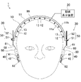
- FIG. 1 is a schematic diagram showing an electroencephalogram detection system in a state where an electroencephalogram measuring device is attached to a part according to an embodiment;
- FIG. 1 is a schematic diagram showing an electroencephalogram detection system with an electroencephalogram measuring device attached to the head according to an embodiment;
- FIG. 1 is a front view of an electroencephalogram detection electrode according to an embodiment;
- FIG. 1 is a plan view of an electroencephalogram detection electrode according to an embodiment;
- FIG. 4 is an enlarged view of a partial area X1 of FIG. 3 according to the embodiment;
- FIG. 5 is a cross-sectional view taken along line X2-X2 of FIG. 4 according to the embodiment;
- FIG. 5 is a diagram showing another example of the X2-X2 cross-sectional view of FIG.
- FIG. 10 is a plan view of another example (form 2) of the electroencephalogram detection electrode according to the embodiment;
- FIG. 11 is a plan view of another example (form 3) of the electroencephalogram detection electrode according to the embodiment;
- FIG. 10 is a plan view of another example (form 4) of the electroencephalogram detection electrode according to the embodiment;
- FIG. 11 is a plan view of another example (form 5) of the electroencephalogram detection electrode according to the embodiment;
- FIG. 11 is a plan view of another example (form 6) of the electroencephalogram detection electrode according to the embodiment;
- FIG. 11 is a plan view of another example (mode 7) of the electroencephalogram detection electrode according to the embodiment;
- FIG. 11 is a plan view of another example (Eighth Embodiment) of the electroencephalogram detection electrode according to the embodiment
- FIG. 12 is a plan view of another example (Mode 9) of the electroencephalogram detection electrode according to the embodiment
- FIG. 12 is a plan view of another example (Mode 10) of the electroencephalogram detection electrode according to the embodiment
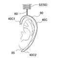
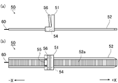
- It is a schematic diagram of the ear attachment part which concerns on embodiment. It is a figure which shows another example (form 2) of the ear-attachment part which concerns on embodiment. It is a figure which shows another example (form 3) of the ear-attachment part which concerns on embodiment. It is a figure which shows another example (form 4) of the ear-attachment part which concerns on embodiment. It is a figure which shows the attachment part which concerns on embodiment.
- FIG. 1 and 2 are schematic diagrams showing the electroencephalogram detection system 1 with the electroencephalogram measurement device 10 attached to the head 99 of a person.
- FIG. 1 is a front view of a person wearing the device.
- FIG. 2 is a side view of a person wearing the device.
- the electroencephalogram detection system 1 includes an electroencephalogram measurement device 10 and an electroencephalogram display device 20 .
- the electroencephalogram measurement device 10 is attached to a person's head 99 and detects electroencephalograms as potential fluctuations from the living body, and outputs the detected electroencephalograms to the electroencephalogram display device 20 .
- the electroencephalogram display device 20 acquires electroencephalograms detected by the electroencephalogram measurement device 10, displays them on a monitor, stores data, and performs well-known electroencephalogram analysis processing (measurement processing).
- the electroencephalogram measuring apparatus 10 includes a rubber-like elastic band member 11 that is attached so as to follow the shape of the human head 99, and a band member 11 that is suitable for the head 99. and a follow-up support unit 30 that assists to follow (follow).
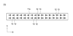
- a plurality of elastic protrusions 12 integrally formed with the band member 11 are provided on one surface of the band member 11 (here, the band inner surface 11a on the head 99 side). At least the tip portion of the protrusion 12 constitutes an electrode portion 13 made of a conductive member.
- the tracking support parts 30 are provided at both ends of the band member 11 in the longitudinal direction.
- a connecting portion 60 (connecting member) provided across the portion 40 and the mounting portion 50 is provided.
- the electroencephalogram measurement device 10 is provided with connectors, electronic components, etc., and is connected to the electroencephalogram display device 20 .
- the electroencephalogram measurement device 10 and the electroencephalogram display device 20 may be configured integrally.
- the electroencephalogram display device 20 may be composed of a smart device (smart phone, tablet terminal) and a predetermined application functioning therewith. In this case, the electroencephalogram measurement device 10 has a communication function of wirelessly transmitting detected electroencephalograms.
- the electroencephalogram display device 20 has, for example, a control section, a storage section, a user IF, an output section, and an electroencephalogram processing data processing section. These include arithmetic units such as CPUs, memories such as ROMs and RAMs, storage devices such as HDDs and SSDs, monitors, communication IFs, etc., and are capable of using electroencephalograms obtained from the electroencephalogram measuring apparatus 10 according to a predetermined program. Convert to data format and perform well-known electroencephalogram analysis functions.
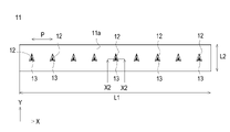
- FIG. 3 is a front view of the band member 11.
- FIG. 4 is a plan view of the band member 11.
- the band member 11 which was curved in FIG. 1, is shown in a flat state.
- the thickness direction of the band member 11 is the Z direction (the upward direction is +Z)
- the longitudinal direction of the rectangular shape is the X direction (the right direction is +X)
- the lateral direction is the Y direction. (The depth direction is +Y).
- the back side (+Y side) will be described as the front side
- the near side ( ⁇ Y side) as the rear side. 8 to 16 variations of the band member 11 will be described.
- the band member 11 described in FIGS. 10 will be described.
- the band member 11 is a plate-like body with a predetermined thickness t. Specifically, the band member 11 has a strip-like rectangular shape when viewed from above (plan view). A thickness t of the band member 11 is, for example, 0.1 mm to 30 mm.
- the longitudinal length L1 of the rectangular shape is, for example, 20 cm to 65 cm.
- the length L2 of the rectangular shape in the lateral direction is, for example, 0.5 cm to 5 cm.
- the shape of the band member 11 is not limited to a strip-like rectangular shape. For example, an elongated elliptical shape may be used instead of a rectangular shape.
- the thickness t of the band member 11 is not limited to a constant value, and the thickness may be partially thinned or thickened. In any case, the band member 11 follows the shape of the head 99 when the electroencephalogram measuring device 10 is worn on the head 99 .
- a plurality of projecting portions 12 are provided integrally with the band member 11 on one surface of the band member 11 (band inner surface 11a on the head 99 side).
- the plurality of protrusions 12 are arranged in a row at a predetermined pitch P when viewed from above.
- the pitch P of the protrusions 12 (that is, the electrode portions 13) is, for example, 1 mm to 20 mm.
- the pitch P is determined from the viewpoint of the number of electrode units 13 required for brain wave detection and the followability of the band member 11 to the head 99 .
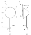
- FIG. 5 is a diagram showing one protrusion 12 by enlarging the region X1 in the front view of FIG. 6 is a cross-sectional view taken along line X2-X2 in FIG. 4, and is also a cross-sectional view of the protrusion 12 in FIG.
- the protrusion 12 is formed integrally with the band member 11 so as to protrude from one surface of the band member 11 (in this case, the band inner surface 11a).
- An attachment portion 50 is attached to the surface on which the protrusion 12 is not provided (here, the band outer surface 11b).
- the height h1 of the triangular pyramid projection 12 is, for example, 0.5 mm to 20 mm, preferably 3 mm to 15 mm, and more preferably 4 mm to 10 mm.
- the protrusion 12 As a specific shape of the triangular pyramid that the protrusion 12 exhibits, for example, as shown in FIG. Yes, they are oriented.
- the vertices of the isosceles triangle are on one side (the front side (+Y side) in the drawing) in the short direction of the rectangular shape, and the base is on the other side (the rear side ( ⁇ Y side) in the drawing).
- the apex of the triangular pyramid that is, the tip of the protrusion 12
- the protruding portion 12 is oriented such that the front side (+Y side) is gentle and the rear side ( ⁇ Y side) is steep.
- the direction of the projection 12 means "the direction in which the vertices of the isosceles triangle face”.
- the protruding portion 12 is applied to the head 99 from the gentle side (+Y side), so that the subject does not feel discomfort (pain, etc.) and the hair is removed.
- the electroencephalogram measurement device 10 can be attached smoothly with little resistance from the outside.
- An electrode portion 13 made of a conductive member is provided at least at the tip of the protrusion 12 so as to cover the surface of the protrusion 12 .
- the electrode portion 13 is provided on the surface of the projection 12 within a predetermined height h2 from the apex of the triangular pyramid.
- the predetermined height h2 at which the electrode portion 13 is formed is, for example, 1 mm to 10 mm, depending on the height h1 of the projection portion 12.
- the conductive member of the electrode portion 13 is, for example, a paste containing a highly conductive metal.
- Good conductive metals include one or more selected from the group consisting of copper, silver, gold, nickel, tin, lead, zinc, bismuth, antimony, or alloys thereof.
- silver, silver chloride, and copper are suitable from the viewpoint of availability and conductivity.
- the electrode part 13 When forming the electrode part 13 with a paste containing a highly conductive metal, the top of the protrusion 12 made of a rubber-like elastic body is dipped (immersion coating) in a paste-like conductive solution containing a highly conductive metal. do. As a result, the electrode portion 13 is formed on the surface of the tip portion of the projection portion 12 .
- the electrode portion 13 as a conductive resin layer may be formed by applying a conductive solution containing a conductive filler and a solvent to the tip portion of the projection portion 12 .
- a conductive solution containing a conductive filler and a solvent to the tip portion of the projection portion 12 .
- the adhesion of the electrode portions 13 (conductive resin layer) can be enhanced.
- a conductive signal line 14 connected to the electrode portion 13 is provided inside the projection portion 12 .
- the material, thickness, and position of the signal line 14 are not particularly limited as long as the connected electroencephalogram display device 20 or the like can appropriately measure electroencephalograms.
- the electrode portion 13 is provided on the surface of the tip portion of the projection portion 12, for example, as shown in FIG. Line 14 is connected.
- the signal line 14 is electrically connected to the electrode portion 13 covering the tip of the protrusion 12 and is arranged inside the protrusion 12 from the tip toward the band member 11 .
- the signal line 14 can use a known one, and can be made of conductive fiber, for example.
- conductive fiber one or more selected from the group consisting of metal fiber, metal-coated fiber, carbon fiber, conductive polymer fiber, conductive polymer-coated fiber, and conductive paste-coated fiber can be used. These may be used alone or in combination of two or more.
- the metal material of the metal fibers and metal-coated fibers is not limited as long as it has conductivity, but copper, silver, gold, nickel, tin, lead, zinc, bismuth, antimony, stainless steel, aluminum, silver/chloride silver and alloys thereof; These may be used alone or in combination of two or more. Among these, silver can be used from the viewpoint of conductivity. Moreover, it is preferable that the metal material does not contain a metal such as chromium that causes a load on the environment.
- the fiber materials of the metal-coated fibers, conductive polymer-coated fibers, and conductive paste-coated fibers are not particularly limited, but may be synthetic fibers, semi-synthetic fibers, or natural fibers. Among these, it is preferable to use polyester, nylon, polyurethane, silk, cotton, and the like. These may be used alone or in combination of two or more.
- Examples of the carbon fibers include PAN-based carbon fibers and pitch-based carbon fibers.
- the conductive polymer material of the conductive polymer fiber and the conductive polymer-coated fiber is, for example, a mixture of a conductive polymer such as polythiophene, polypyrrole, polyaniline, polyacetylene, polyphenylene vinylene, polynaphthalene, and derivatives thereof and a binder resin, Alternatively, an aqueous solution of a conductive polymer such as PEDOT-PSS ((3,4-ethylenedioxythiophene)-poly(styrenesulfonic acid)) is used.
- PEDOT-PSS ((3,4-ethylenedioxythiophene)-poly(styrenesulfonic acid)
- the resin material contained in the conductive paste of the conductive paste-coated fiber is not particularly limited, but preferably has elasticity. It can contain one or more selected from the group consisting of propylene rubbers. These may be used alone or in combination of two or more.
- the conductive filler contained in the conductive paste of the conductive paste-coated fiber is not particularly limited, and known conductive materials may be used, such as metal particles, metal fibers, metal-coated fibers, carbon black, acetylene black, graphite, carbon It may contain one or more selected from the group consisting of fibers, carbon nanotubes, conductive polymers, conductive polymer-coated fibers and metal nanowires.
- the metal constituting the conductive filler is not particularly limited, but for example, copper, silver, gold, nickel, tin, lead, zinc, bismuth, antimony, silver/silver chloride, or at least one of these alloys. or, alternatively, two or more of these.
- silver or copper is preferable because of its high conductivity and high availability.
- the signal line 14 may be composed of twisted yarn obtained by twisting a plurality of linear conductive fibers. Thereby, disconnection of the signal line 14 at the time of deformation can be suppressed.
- the coating of the conductive fiber means not only covering the outer surface of the fiber material, but also, in the case of a twisted yarn obtained by twisting single fibers, a metal or a conductive polymer is added between the fibers in the twisted yarn. , or impregnated with a conductive paste to cover each single fiber constituting the twisted yarn.
- the tensile elongation at break of the signal line 14 is, for example, 1% to 50%, preferably 1.5% to 45%. By setting the value within such a numerical range, it is possible to suppress excessive deformation of the protrusion 12 while suppressing breakage during deformation.
- the signal line 14 can adopt various arrangement structures as long as it is a mode that conducts the inside of the protrusion 12 .
- the tip of the signal line 14 may be any of a protruding structure, a structure on substantially the same plane, and a buried structure with respect to the tip of the protrusion 12 or the inclined surface of the tip. From the viewpoint of connection stability with the electrode portion 13, a projecting structure may be used. A projecting portion at the tip of the signal line 14 is partially or entirely covered with the electrode portion 13 .
- the protruding structure of the tip of the signal line 14 may be unfolded, folded, or wrapped around the surface of the tip of the projection 12 . Also, the signal line 14 may not coincide with the vertical line extending from the tip (apex) of the protrusion 12 and may be inclined with respect to the vertical line.
- the signal line 14 is connected to the lower end of the electrode portion 13 (on the side of the band member 11), extends along the slope (surface) of the projection portion 12, and reaches a predetermined level. It may be in the form of being retracted into the protrusion 12 from the position.
- the end on the side connected to the electrode portion 13 and the end on the opposite side may be individually pulled out of the band member 11 .
- the plurality of signal lines 14 may be connected to a connector or the like provided on the band outer surface 11b of the band member 11 from inside the band member 11 and organized.
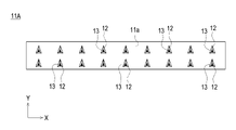
- FIG. 8 shows a plan view of the band member 11A of form 2.
- the difference from form 1 is mainly in the arrangement of the protrusions 12 . That is, in form 1, the plurality of protrusions 12 are arranged in a row in the same direction.
- a plurality of protrusions 12 are arranged in two rows. That is, it can be said that it is the structure which added one more line of the protrusion part 12 of the form 1.
- FIG. In other words, the plurality of protrusions 12 are arranged in a grid pattern (regular grid pattern).
- a plurality of projections 12 are arranged in a grid pattern (regular grid pattern). This makes it possible to realize the effects of the first form and to arrange the protrusions 12 (that is, the electrode parts 13) suitable for electroencephalogram detection. That is, stable electroencephalogram detection can be realized.
- FIG. 9 shows a plan view of the band member 11B of form 2.
- the difference from form 1 is mainly in the arrangement of the protrusions 12 . That is, in form 1, the plurality of protrusions 12 are arranged in a row in the same direction. On the other hand, in form 3, a plurality of protrusions 12 are arranged in two rows. However, unlike the band member 11A of form 2, the protrusions 12 are arranged alternately. In other words, the plurality of protrusions 12 are arranged in a houndstooth pattern.
- a plurality of protrusions 12 are arranged in a houndstooth pattern. This makes it possible to realize the effects of the first form and to arrange the protrusions 12 (that is, the electrode parts 13) suitable for electroencephalogram detection. That is, stable electroencephalogram detection can be realized.
- FIG. 10 shows a plan view of the band member 11C of form 4.
- the plurality of protrusions 12 are arranged in two rows, and the number (density) of the protrusions 12 in the front row (+Y side row) is reduced.
- the protrusions 12 in the row on the rear side ( ⁇ Y side row) in the drawing are arranged at a predetermined first pitch Pc1 .
- the protrusions 12 in the back row (+Y side) are arranged at a predetermined second pitch P c2 (for example, twice the first pitch P c1 ).
- P c2 for example, twice the first pitch P c1
- the band member 11C of this embodiment a plurality of protrusions 12 are alternately arranged with different densities. This makes it possible to realize the effects of the first form and to arrange the protrusions 12 (that is, the electrode parts 13) suitable for electroencephalogram detection. That is, stable electroencephalogram detection can be realized.
- the human head 99 has a common fixed shape.
- the position of the head 99 on which the electroencephalogram measurement device 10 (the band member 11C) is worn and the shape of the position of the head 99 touched when the device is worn have certain characteristics. The band member 11C can well follow such characteristics.
- FIG. 11 shows a plan view of a band member 11D of form 5.
- the band member 11D of this embodiment is the same as the first embodiment in that a plurality of protrusions 12 are arranged in a line, but the directions of the protrusions 12 are different. This makes it possible to appropriately correspond to the flow of hair.
- the projections 12 on the left half (eight on the left) in the figure are oriented rightward (that is, toward the center in the longitudinal direction of the band member 11), and the projections on the right half (eight on the right) in the figure 12 is oriented leftward (that is, oriented toward the center in the longitudinal direction of the band member 11D).
- the electroencephalogram measurement device 10 the band member 11D
- each protrusion 12 faces the top of the head 99. Therefore, the electroencephalogram measurement device 10 (band member 11D) can be worn while appropriately following the flow and amount of hair on the head 99 .
- the band member 11D is worn in a curved state from a flat state, the gentle side of the protrusion 12 comes into contact with the head 99, so discomfort can be avoided.
- FIG. 12 shows a plan view of the band member 11E of form 6.
- the band member 11E of this embodiment is the same as the embodiments 1 and 5 in that a plurality of protrusions 12 are arranged in a row, but the directions of the protrusions 12 are different. This makes it possible to appropriately correspond to the flow of hair.
- the projections 12 on the left half (eight on the left) in the illustration are oriented leftward (that is, toward the left end in the longitudinal direction of the band member 11), and on the right half (eight on the right) in the illustration.
- the projection 12 is oriented rightward (that is, oriented toward the right end in the longitudinal direction of the band member 11E).
- each protrusion 12 can be said to face downward (toward the position of the ear) from the top of the head 99.
- each protrusion 12 faces downward from the top of the head 99. . Therefore, the electroencephalogram measurement device 10 (band member 11E) can be worn while properly following the flow and amount of hair on the head 99 .
- the band member 11E is attached to the inner surface 11a of the band while being curved to some extent, the gentle side of the protrusion 12 comes into contact with the head 99, thereby avoiding discomfort.
- FIG. 13 shows a plan view of the band member 11F of form 7.
- two projections 12 facing each other are additionally provided at the longitudinal center of the band member 11F.
- the protrusion 12 on the front side (+Y side) in the illustration faces backward ( ⁇ Y direction), and the protrusion 12 on the rear side ( ⁇ Y side) in the illustration is forward (+Y direction). That is, there are provided two opposing protrusions 12 facing the center of the band member 11F (band inner surface 11a) (centers in the longitudinal direction and the lateral direction) when viewed from above.
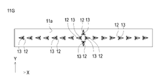
- FIG. 14 shows a plan view of the band member 11G of form 8.
- two projections 12 facing each other are additionally provided at the longitudinal center of the band member 11G. ing.
- the protrusion 12 on the front side (+Y side) in the illustration is forward (+Y direction)
- the protrusion 12 on the rear side ( ⁇ Y side) in the illustration is backward (-Y direction). That is, two projections 12 are provided at the center of the band member 11G (the inner surface 11a of the band) (centers in the longitudinal direction and the lateral direction) when viewed from above.
- the band member 11G of this embodiment With the band member 11G of this embodiment, the same effect as the band member 11E of the sixth embodiment can be obtained. Furthermore, the addition of the above-described two back-facing protrusions 12 improves the wearability of the electroencephalogram measurement device 10 (band member 11G) on the head 99, especially the function of the protrusions 12 to penetrate and stabilize the hair. can be improved.
- the band member 11H of this form With the band member 11H of this form, the same effect as the band member 11D of form 5 can be obtained. Furthermore, by arranging the plurality of protrusions 12 in two rows, one on the front side and the other on the back side, the same effect as the band member 11B of form 2, that is, the placement of the protrusions 12 (that is, the electrode parts 13) suitable for electroencephalogram detection is possible, and stable electroencephalogram detection can be realized.
- the rows of the plurality of projecting portions 12 of the band member 11E of form 6 are arranged in front and rear two rows.
- the features of the second and sixth modes are combined.
- the projections 12 of the left half are oriented leftward (that is, toward the left end in the longitudinal direction of the band member 11E) and rightward in the illustration.
- the orientation of half is to the right (that is, to the right end in the longitudinal direction of the band member 11E).
- the same effect as the band member 11E of the fifth embodiment can be obtained. Furthermore, by arranging the plurality of protrusions 12 in two rows, one on the front side and the other on the back side, the same effect as the band member 11B of form 2, that is, the placement of the protrusions 12 (that is, the electrode parts 13) suitable for electroencephalogram detection is possible, and stable electroencephalogram detection can be realized.
- Embodiments 1 to 10 a triangular pyramid was exemplified as the shape of the protrusion 12, but other pyramids such as cones and square pyramids, and truncated pyramids obtained by removing the top of the pyramid may be used. .
- the band member 11 and the protrusion 12 are rubber-like elastic bodies, more specifically, rubber or thermoplastic elastomer (also simply referred to as “elastomer (TPE)").
- rubber include silicone rubber.
- thermoplastic elastomers include styrene-based TPE (TPS), olefin-based TPE (TPO), vinyl chloride-based TPE (TPVC), urethane-based TPE (TPU), ester-based TPE (TPEE), and amide-based TPE (TPAE).
- the band member 11 and projections 12 of the electroencephalogram measurement device 10 are made of silicone rubber, the surface of the band member 11 (band inner surface 11a and band outer surface 11b) measured at 37°C in accordance with JIS K 6253 (1997).
- Rubber hardness A is, for example, 15 or more and 55 or less.
- the silicone rubber-based curable composition will be described.
- the silicone rubber can be composed of a cured product of a silicone rubber-based curable composition.
- the curing step of the silicone rubber-based curable resin composition is, for example, heating at 100 to 250° C. for 1 to 30 minutes (primary curing), followed by post-baking (secondary curing) at 100 to 200° C. for 1 to 4 hours. It is done by
- An insulating silicone rubber is a silicone rubber that does not contain a conductive filler
- a conductive silicone rubber is a silicone rubber that contains a conductive filler
- the silicone rubber-based curable composition according to this embodiment can contain a vinyl group-containing organopolysiloxane (A).
- the vinyl group-containing organopolysiloxane (A) is a polymer that is the main component of the silicone rubber-based curable composition of the present embodiment.
- the insulating silicone rubber-based curable composition and the conductive silicone rubber-based curable composition may contain the same vinyl group-containing linear organopolysiloxane.
- the vinyl group-containing linear organopolysiloxane of the same kind includes at least the same vinyl group with the same functional group and has a linear shape. can be different.
- the insulating silicone rubber-based curable composition and the conductive silicone rubber-based curable composition may further contain different vinyl group-containing organopolysiloxanes.
- the vinyl group-containing organopolysiloxane (A) can contain a vinyl group-containing linear organopolysiloxane (A1) having a linear structure.
- the vinyl group-containing linear organopolysiloxane (A1) has a linear structure and contains vinyl groups, and the vinyl groups serve as cross-linking points during curing.
- the vinyl group content of the vinyl group-containing linear organopolysiloxane (A1) is not particularly limited, but for example, it preferably has two or more vinyl groups in the molecule and is 15 mol % or less. , 0.01 to 12 mol %.
- the amount of vinyl groups in the vinyl group-containing linear organopolysiloxane (A1) is optimized, and a network can be reliably formed with each component described later.
- " ⁇ " means including both numerical values.
- the vinyl group content is the mol % of the vinyl group-containing siloxane units when the total units constituting the vinyl group-containing linear organopolysiloxane (A1) are taken as 100 mol %. .
- one vinyl group is considered to be one vinyl group-containing siloxane unit.
- the degree of polymerization of the vinyl group-containing linear organopolysiloxane (A1) is not particularly limited, it is, for example, preferably in the range of about 1,000 to 10,000, more preferably in the range of about 2,000 to 5,000.
- the degree of polymerization can be determined, for example, as a polystyrene-equivalent number-average polymerization degree (or number-average molecular weight) in GPC (gel permeation chromatography) using chloroform as a developing solvent.
- the specific gravity of the vinyl group-containing linear organopolysiloxane (A1) is not particularly limited, but is preferably in the range of about 0.9 to 1.1.
- the heat resistance, flame retardancy, chemical stability, etc. of the resulting silicone rubber can be improved by using those having the degree of polymerization and specific gravity within the ranges described above. can be improved.
- vinyl group-containing linear organopolysiloxane (A1) those having a structure represented by the following formula (1) are particularly preferable.
- R 1 is a substituted or unsubstituted alkyl group, alkenyl group, aryl group, or a hydrocarbon group of a combination thereof having 1 to 10 carbon atoms.
- the alkyl group having 1 to 10 carbon atoms includes, for example, methyl group, ethyl group, propyl group, etc. Among them, methyl group is preferable.
- the alkenyl group having 1 to 10 carbon atoms includes, for example, vinyl group, allyl group, butenyl group, etc. Among them, vinyl group is preferred.
- the aryl group having 1 to 10 carbon atoms includes, for example, a phenyl group.
- R 2 is a substituted or unsubstituted alkyl group, alkenyl group, aryl group having 1 to 10 carbon atoms, or a hydrocarbon group combining these.
- the alkyl group having 1 to 10 carbon atoms includes, for example, methyl group, ethyl group, propyl group, etc. Among them, methyl group is preferable.
- alkenyl groups having 1 to 10 carbon atoms include vinyl groups, allyl groups and butenyl groups.
- the aryl group having 1 to 10 carbon atoms include a phenyl group.
- R 3 is a substituted or unsubstituted alkyl group having 1 to 8 carbon atoms, an aryl group, or a hydrocarbon group combining these.
- the alkyl group having 1 to 8 carbon atoms includes, for example, methyl group, ethyl group, propyl group, etc. Among them, methyl group is preferred.
- Examples of the aryl group having 1 to 8 carbon atoms include a phenyl group.
- examples of substituents for R 1 and R 2 in formula (1) include methyl group and vinyl group, and examples of substituents for R 3 include methyl group.
- a plurality of R 1 are independent of each other and may be different or the same. Furthermore, the same applies to R 2 and R 3 .
- m and n are the numbers of repeating units constituting the vinyl group-containing linear organopolysiloxane (A1) represented by formula (1), m is an integer of 0 to 2000, and n is 1000 to 10000. is an integer of m is preferably 0-1000 and n is preferably 2000-5000.
- vinyl group-containing linear organopolysiloxane (A1) represented by formula (1) include, for example, those represented by the following formula (1-1).
- R 1 and R 2 are each independently a methyl group or a vinyl group, and at least one is a vinyl group.
- the vinyl group-containing linear organopolysiloxane (A1) a first vinyl group-containing vinyl group having a vinyl group content of 2 or more vinyl groups in the molecule and not more than 0.4 mol% It contains a linear organopolysiloxane (A1-1) and a second vinyl group-containing linear organopolysiloxane (A1-2) having a vinyl group content of 0.5 to 15 mol%. It is preferable to have As crude rubber, which is a raw material of silicone rubber, a first vinyl group-containing linear organopolysiloxane (A1-1) having a general vinyl group content and a second vinyl group-containing linear organopolysiloxane having a high vinyl group content were used.
- the vinyl groups can be unevenly distributed, and the crosslink density can be more effectively formed in the crosslink network of the silicone rubber. As a result, the tear strength of silicone rubber can be increased more effectively.
- the vinyl group-containing linear organopolysiloxane (A1) for example, a unit in which R 1 is a vinyl group and/or a unit in which R 2 is a vinyl group in the above formula (1-1) , a first vinyl group-containing linear organopolysiloxane (A1-1) having 2 or more in the molecule and containing 0.4 mol% or less, and a unit in which R 1 is a vinyl group and / or R It is preferable to use a second vinyl group-containing linear organopolysiloxane (A1-2) containing 0.5 to 15 mol % of units in which 2 is a vinyl group.
- the first vinyl group-containing linear organopolysiloxane (A1-1) preferably has a vinyl group content of 0.01 to 0.2 mol %.
- the second vinyl group-containing linear organopolysiloxane (A1-2) preferably has a vinyl group content of 0.8 to 12 mol %.
- (A1-1) and (A1-2) are not particularly limited, but for example, the weight ratio of (A1-1):(A1-2) is preferably 50:50 to 95:5, and 80:20 to 90: 10 is more preferred.
- the first and second vinyl group-containing linear organopolysiloxanes (A1-1) and (A1-2) may be used singly or in combination of two or more. good.
- the vinyl group-containing organopolysiloxane (A) may also contain a vinyl group-containing branched organopolysiloxane (A2) having a branched structure.
- the silicone rubber-based curable composition of the present embodiment may contain a cross-linking agent.
- Cross-linking agents can include organohydrogenpolysiloxanes (B).
- Organohydrogenpolysiloxane (B) is classified into linear organohydrogenpolysiloxane (B1) having a linear structure and branched organohydrogenpolysiloxane (B2) having a branched structure. Either or both may be included.
- the insulating silicone rubber-based curable composition and the conductive silicone rubber-based curable composition may contain the same type of cross-linking agent.
- the same type of cross-linking agent should have at least a common structure such as a linear structure or a branched structure, and may contain different molecular weight distributions and different functional groups in the molecule, and the amount added may be different.
- the insulating silicone rubber-based curable composition and the conductive silicone rubber-based curable composition may further contain different cross-linking agents.
- the linear organohydrogenpolysiloxane (B1) has a linear structure and a structure ( ⁇ Si—H) in which hydrogen is directly bonded to Si, and is the vinyl group-containing organopolysiloxane (A). It is a polymer that undergoes a hydrosilylation reaction with other vinyl groups and other vinyl groups contained in other components of the silicone rubber-based curable composition to crosslink these components.
- the molecular weight of the linear organohydrogenpolysiloxane (B1) is not particularly limited, for example, the weight average molecular weight is preferably 20,000 or less, more preferably 1,000 or more and 10,000 or less.
- the weight average molecular weight of the linear organohydrogenpolysiloxane (B1) can be measured, for example, by polystyrene conversion in GPC (gel permeation chromatography) using chloroform as a developing solvent.
- the linear organohydrogenpolysiloxane (B1) does not have a vinyl group. Thereby, it is possible to accurately prevent the progress of the cross-linking reaction in the molecule of the linear organohydrogenpolysiloxane (B1).
- linear organohydrogenpolysiloxane (B1) for example, one having a structure represented by the following formula (2) is preferably used.
- R 4 is a substituted or unsubstituted alkyl group, alkenyl group, aryl group having 1 to 10 carbon atoms, a hydrocarbon group combining these groups, or a hydride group.
- the alkyl group having 1 to 10 carbon atoms includes, for example, methyl group, ethyl group, propyl group, etc. Among them, methyl group is preferable.
- alkenyl groups having 1 to 10 carbon atoms include vinyl groups, allyl groups and butenyl groups.
- the aryl group having 1 to 10 carbon atoms include a phenyl group.
- R 5 is a substituted or unsubstituted alkyl group, alkenyl group, aryl group having 1 to 10 carbon atoms, a hydrocarbon group combining these, or a hydride group.
- alkyl group having 1 to 10 carbon atoms include methyl group, ethyl group and propyl group, with methyl group being preferred.
- alkenyl groups having 1 to 10 carbon atoms include vinyl groups, allyl groups and butenyl groups.
- Examples of the aryl group having 1 to 10 carbon atoms include a phenyl group.
- a plurality of R 4 are independent of each other and may be different from each other or may be the same. The same is true for R5. However, at least two or more of the plurality of R 4 and R 5 are hydride groups.
- R 6 is a substituted or unsubstituted alkyl group having 1 to 8 carbon atoms, an aryl group, or a hydrocarbon group combining these.
- the alkyl group having 1 to 8 carbon atoms includes, for example, methyl group, ethyl group, propyl group, etc. Among them, methyl group is preferred.
- Examples of the aryl group having 1 to 8 carbon atoms include a phenyl group.
- a plurality of R 6 are independent from each other and may be different from each other or may be the same.
- substituents for R 4 , R 5 and R 6 in formula (2) include methyl group and vinyl group, and methyl group is preferred from the viewpoint of preventing intramolecular cross-linking reaction.
- m and n are the numbers of repeating units constituting the linear organohydrogenpolysiloxane (B1) represented by formula (2), m is an integer of 2 to 150, and n is an integer of 2 to 150. is.
- m is an integer from 2-100 and n is an integer from 2-100.
- the straight-chain organohydrogenpolysiloxane (B1) may be used alone or in combination of two or more.
- the branched organohydrogenpolysiloxane (B2) has a branched structure, it is a component that forms regions with a high crosslink density and greatly contributes to the formation of a loose and dense structure of crosslink density in the silicone rubber system. Further, like the linear organohydrogenpolysiloxane (B1), it has a structure ( ⁇ Si—H) in which hydrogen is directly bonded to Si, and in addition to the vinyl group of the vinyl group-containing organopolysiloxane (A), silicone It is a polymer that undergoes a hydrosilylation reaction with the vinyl groups of the components blended in the rubber-based curable composition to crosslink these components.
- the specific gravity of the branched organohydrogenpolysiloxane (B2) is in the range of 0.9 to 0.95.
- the branched organohydrogenpolysiloxane (B2) does not have a vinyl group. Thereby, it is possible to accurately prevent the progress of the cross-linking reaction in the molecule of the branched organohydrogenpolysiloxane (B2).
- branched organohydrogenpolysiloxane (B2) one represented by the following average compositional formula (c) is preferable.
- R 7 is a monovalent organic group, a is an integer ranging from 1 to 3, m is the number of H a (R 7 ) 3-a SiO 1/2 units, n is SiO 4/ is a number of 2 units)
- R 7 is a monovalent organic group, preferably a substituted or unsubstituted alkyl group having 1 to 10 carbon atoms, an aryl group, or a hydrocarbon group combining these.
- the alkyl group having 1 to 10 carbon atoms includes, for example, methyl group, ethyl group, propyl group, etc. Among them, methyl group is preferred.
- Examples of the aryl group having 1 to 10 carbon atoms include a phenyl group.
- a is the number of hydride groups (hydrogen atoms directly bonded to Si) and is an integer in the range of 1 to 3, preferably 1.
- m is the number of H a (R 7 ) 3-a SiO 1/2 units
- n is the number of SiO 4/2 units.
- the branched organohydrogenpolysiloxane (B2) has a branched structure.
- the linear organohydrogenpolysiloxane (B1) and the branched organohydrogenpolysiloxane (B2) differ in that their structures are linear or branched.
- the number of bound alkyl groups R (R/Si) is 1.8 to 2.1 for the linear organohydrogenpolysiloxane (B1) and 0.8 to 1 for the branched organohydrogenpolysiloxane (B2). .7 range.
- the branched organohydrogenpolysiloxane (B2) has a branched structure, for example, when heated to 1000° C. at a heating rate of 10° C./min in a nitrogen atmosphere, the residual amount is 5% or more. becomes.
- the straight-chain organohydrogenpolysiloxane (B1) is straight-chain, the amount of residue after heating under the above conditions is almost zero.
- branched organohydrogenpolysiloxane (B2) include those having a structure represented by the following formula (3).
- R 7 is a substituted or unsubstituted alkyl group having 1 to 8 carbon atoms, an aryl group, a hydrocarbon group combining these, or a hydrogen atom.
- the alkyl group having 1 to 8 carbon atoms includes, for example, methyl group, ethyl group, propyl group, etc. Among them, methyl group is preferable.
- Examples of the aryl group having 1 to 8 carbon atoms include a phenyl group.
- the substituent of R7 include a methyl group and the like.
- a plurality of R 7 are independent of each other and may be different from each other or may be the same.
- the branched organohydrogenpolysiloxane (B2) may be used alone or in combination of two or more.
- the amount of hydrogen atoms (hydride groups) directly bonded to Si is not particularly limited.
- linear organohydrogenpolysiloxane (B1) and branched organohydrogenpolysiloxane are The total amount of hydride groups in the siloxane (B2) is preferably from 0.5 to 5 mol, more preferably from 1 to 3.5 mol.
- the silicone rubber-based curable composition according to this embodiment contains a non-conductive filler.
- the non-conductive filler may contain silica particles (C) as needed. Thereby, the hardness and mechanical strength of the elastomer can be improved.
- the insulating silicone rubber-based curable composition and the conductive silicone rubber-based curable composition may contain the same type of non-conductive filler.
- Non-conductive fillers of the same type may have at least common constituent materials, and may differ in particle size, specific surface area, surface treatment agent, or addition amount thereof.
- the insulating silicone rubber-based curable composition and the conductive silicone rubber-based curable composition may further contain different silane coupling agents.
- the silica particles (C) are not particularly limited, but for example, fumed silica, calcined silica, precipitated silica, etc. are used. These may be used alone or in combination of two or more.
- the silica particles (C) preferably have a BET specific surface area of, for example, 50 to 400 m 2 /g, more preferably 100 to 400 m 2 /g. Also, the average primary particle size of the silica particles (C) is, for example, preferably 1 to 100 nm, more preferably about 5 to 20 nm.
- silica particles (C) having a specific surface area and an average particle size within the above ranges, the hardness and mechanical strength of the formed silicone rubber can be improved, especially the tensile strength can be improved.
- the silicone rubber-based curable composition of the present embodiment can contain a silane coupling agent (D).
- Silane coupling agent (D) can have a hydrolyzable group. The hydrolyzable group is hydrolyzed with water to form a hydroxyl group, and the hydroxyl group undergoes a dehydration condensation reaction with the hydroxyl group on the surface of the silica particle (C), thereby modifying the surface of the silica particle (C).
- the insulating silicone rubber-based curable composition and the conductive silicone rubber-based curable composition may contain the same type of silane coupling agent.
- the silane coupling agents of the same kind should have at least a common functional group, and may differ in other functional groups in the molecule and in the amount added.
- the insulating silicone rubber-based curable composition and the conductive silicone rubber-based curable composition may further contain different silane coupling agents.
- this silane coupling agent (D) can contain a silane coupling agent having a hydrophobic group.
- the hydrophobic group is imparted to the surface of the silica particles (C), so that the cohesive force of the silica particles (C) in the silicone rubber-based curable composition and further in the silicone rubber is reduced (hydrogen aggregation due to bonding is reduced), and as a result, it is presumed that the dispersibility of the silica particles (C) in the silicone rubber-based curable composition is improved. This increases the interface between the silica particles (C) and the rubber matrix, increasing the reinforcing effect of the silica particles (C).
- the slipperiness of the silica particles (C) within the matrix is improved when the rubber matrix is deformed.
- the improved dispersibility and slipperiness of the silica particles (C) improve the mechanical strength (for example, tensile strength and tear strength) of the silicone rubber due to the silica particles (C).
- the silane coupling agent (D) can contain a silane coupling agent having a vinyl group.
- vinyl groups are introduced onto the surfaces of the silica particles (C). Therefore, during curing of the silicone rubber-based curable composition, that is, a hydrosilylation reaction occurs between the vinyl group of the vinyl group-containing organopolysiloxane (A) and the hydride group of the organohydrogenpolysiloxane (B). , When a network (crosslinked structure) is formed by these, the vinyl groups possessed by the silica particles (C) also participate in the hydrosilylation reaction with the hydride groups possessed by the organohydrogenpolysiloxane (B). Silica particles (C) also come to be taken in. As a result, it is possible to reduce the hardness and increase the modulus of the formed silicone rubber.
- silane coupling agent (D) a silane coupling agent having a hydrophobic group and a silane coupling agent having a vinyl group can be used in combination.
- silane coupling agent (D) examples include those represented by the following formula (4).
- n represents an integer of 1-3.
- Y represents a functional group having a hydrophobic group, a hydrophilic group or a vinyl group, and when n is 1 it is a hydrophobic group, and when n is 2 or 3 at least one of It is a hydrophobic group.
- X represents a hydrolyzable group.
- the hydrophobic group is an alkyl group having 1 to 6 carbon atoms, an aryl group, or a hydrocarbon group having a combination thereof, and examples thereof include a methyl group, an ethyl group, a propyl group, a phenyl group, and the like. Methyl groups are preferred.
- the hydrophilic group includes, for example, a hydroxyl group, a sulfonic acid group, a carboxyl group, a carbonyl group, etc. Among them, a hydroxyl group is particularly preferable.
- the hydrophilic group may be contained as a functional group, but is preferably not contained from the viewpoint of imparting hydrophobicity to the silane coupling agent (D).
- the hydrolyzable group includes an alkoxy group such as a methoxy group and an ethoxy group, a chloro group, a silazane group, and the like.
- a silazane group is preferable because of its high reactivity with the silica particles (C).
- a compound having a silazane group as a hydrolyzable group has two structures of (Y n —Si—) in the above formula (4) due to its structural characteristics.
- silane coupling agent (D) represented by the above formula (4) are as follows.
- Those having a hydrophobic group as the functional group include, for example, methyltrimethoxysilane, dimethyldimethoxysilane, phenyltrimethoxysilane, methyltriethoxysilane, dimethyldiethoxysilane, phenyltriethoxysilane, n-propyltrimethoxysilane, alkoxysilanes such as n-propyltriethoxysilane, hexyltrimethoxysilane, hexyltriethoxysilane, decyltrimethoxysilane; chlorosilanes such as methyltrichlorosilane, dimethyldichlorosilane, trimethylchlorosilane, phenyltrichlorosilane; hexamethyldisilazane.
- silane coupling agent having a trimethylsilyl group containing one or more selected from the group consisting of hexamethyldisilazane, trimethylchlorosilane, trimethylmethoxysilane, and trimethylethoxysilane is preferred.
- Examples of those having a vinyl group as the functional group include methacryloxypropyltriethoxysilane, methacryloxypropyltrimethoxysilane, methacryloxypropylmethyldiethoxysilane, methacryloxypropylmethyldimethoxysilane, vinyltriethoxysilane, and vinyltrimethoxysilane.
- alkoxysilanes such as silane and vinylmethyldimethoxysilane
- chlorosilanes such as vinyltrichlorosilane and vinylmethyldichlorosilane
- divinyltetramethyldisilazane divinyltetramethyldisilazane.
- a silane coupling agent having a vinyl group-containing organosilyl group containing one or more selected from the group consisting of methyldimethoxysilane is preferred.
- silane coupling agent (D) contains two kinds of a silane coupling agent having a trimethylsilyl group and a silane coupling agent having a vinyl group-containing organosilyl group
- those having a hydrophobic group include hexamethyldisilazane, Divinyltetramethyldisilazane is preferably included as one having a vinyl group.
- the ratio of (D1) and (D2) is not particularly limited, but for example, (D1):(D2) in a weight ratio of 1:0.001 to 1:0.35, preferably 1:0.01 to 1:0.20, more preferably 1:0.03 to 1:0 .15. Desired physical properties of the silicone rubber can be obtained by setting it to such a numerical range. Specifically, the dispersibility of silica in the rubber and the crosslinkability of the rubber can be balanced.
- the lower limit of the content of the silane coupling agent (D) is preferably 1% by mass or more with respect to 100 parts by weight of the total amount of the vinyl group-containing organopolysiloxane (A). It is more preferably at least 5% by mass, even more preferably at least 5% by mass.
- the upper limit of the content of the silane coupling agent (D) is preferably 100% by mass or less, and 80% by mass or less, with respect to 100 parts by weight of the total amount of the vinyl group-containing organopolysiloxane (A). It is more preferable that the content is 40% by mass or less.
- the silicone rubber can have appropriate mechanical properties.
- the silicone rubber-based curable composition according to this embodiment may contain a catalyst.
- the catalyst may contain platinum or a platinum compound (E).
- Platinum or a platinum compound (E) is a catalytic component that acts as a catalyst during curing.
- the amount of platinum or platinum compound (E) added is a catalytic amount.
- the insulating silicone rubber-based curable composition and the conductive silicone rubber-based curable composition may contain the same type of catalyst. Catalysts of the same kind may have at least common constituent materials, and the catalysts may contain different compositions and may differ in addition amount.
- the insulating silicone rubber-based curable composition and the conductive silicone rubber-based curable composition may further contain different catalysts.
- platinum or platinum compound (E) a known one can be used, for example, platinum black, platinum supported on silica or carbon black, chloroplatinic acid or an alcohol solution of chloroplatinic acid, A complex salt of platinic acid and olefin, a complex salt of chloroplatinic acid and vinyl siloxane, and the like are included.
- the platinum or platinum compound (E) may be used alone or in combination of two or more.
- the content of platinum or platinum compound (E) in the silicone rubber-based curable composition means the amount of catalyst, and can be set as appropriate.
- (A), silica particles (C), the total amount of 100 parts by weight of the silane coupling agent (D), platinum group metal is an amount of 0.01 to 1000 ppm by weight unit, preferably 0. The amount is 1 to 500 ppm.
- the silicone rubber-based curable composition according to the present embodiment may contain water (F) in addition to the above components (A) to (E).
- Water (F) is a component that functions as a dispersion medium for dispersing each component contained in the silicone rubber-based curable composition and contributes to the reaction between the silica particles (C) and the silane coupling agent (D). . Therefore, the silica particles (C) and the silane coupling agent (D) can be linked to each other more reliably in the silicone rubber, and uniform properties can be exhibited as a whole.
- the silicone rubber-based curable composition of the present embodiment may further contain other components in addition to the above components (A) to (F).
- Other components include silica particles (C) such as diatomaceous earth, iron oxide, zinc oxide, titanium oxide, barium oxide, magnesium oxide, cerium oxide, calcium carbonate, magnesium carbonate, zinc carbonate, glass wool, and mica.
- additives such as inorganic fillers, reaction inhibitors, dispersants, pigments, dyes, antistatic agents, antioxidants, flame retardants, and thermal conductivity improvers.
- the conductive solution (conductive silicone rubber composition) according to the present embodiment contains the conductive filler and solvent in addition to the silicone rubber-based curable composition containing no conductive filler.
- solvents can be used as the solvent, and for example, a high boiling point solvent can be included. These may be used alone or in combination of two or more.
- solvents examples include aliphatic hydrocarbons such as pentane, hexane, cyclohexane, heptane, methylcyclohexane, ethylcyclohexane, octane, decane, dodecane, and tetradecane; benzene, toluene, ethylbenzene, xylene, trifluoromethylbenzene; , aromatic hydrocarbons such as benzotrifluoride; diethyl ether, diisopropyl ether, dibutyl ether, cyclopentyl methyl ether, cyclopentyl ethyl ether, ethylene glycol dimethyl ether, ethylene glycol diethyl ether, diethylene glycol dimethyl ether, 1,4-dioxane, 1,3 - ethers such as dioxane and tetrahydrofuran; haloalkanes such as
- the conductive solution can have a viscosity suitable for various coating methods such as spray coating and dip coating.
- the lower limit of the content of the silica particles (C) contained in the electrode portion 13 is the amount of the silica particles (C) and the conductive filler. For example, it is 1% by mass or more, preferably 3% by mass or more, and more preferably 5% by mass or more, relative to the total amount of 100% by mass. Thereby, the mechanical strength of the electrode portion 13 can be improved.
- the upper limit of the content of the silica particles (C) contained in the electrode portion 13 is, for example, 20% by mass or less with respect to the total amount of 100% by mass of the silica particles (C) and the conductive filler, It is preferably 15% by mass or less, more preferably 10% by mass or less. Thereby, it is possible to achieve a balance between conductivity, mechanical strength, and flexibility in the electrode portion 13 .
- a conductive silicone rubber can be obtained by heating and drying the conductive solution as necessary.
- the conductive silicone rubber may be configured without silicone oil. As a result, it is possible to suppress a decrease in conductivity due to bleeding out of the silicone oil onto the surface of the electrode portion 13 .
- the band member 11 and the plurality of protrusions 12 are seamlessly joined by molding a curable elastomer composition such as a silicone rubber-based curable composition. you get a body As a result, the electroencephalogram measurement device 10 that is excellent in flexibility (that is, flexibility that can follow the head 99 ) and strength and that can follow the head 99 well can be realized.
- the rubber hardness A ie flexibility, can be controlled by appropriately selecting the type and amount of each component contained in the silicone rubber curable composition, the preparation method of the silicone rubber curable composition, and the like.
- An example of the method for manufacturing the band member 11 can include the following steps. First, using a mold, the silicone rubber-based curable composition is molded under heat and pressure to obtain a molded body comprising the band member 11 and the protrusions 12 . Subsequently, the signal wire 14 was passed through the interior of each columnar portion of the molded body obtained using a sewing needle. A pasty conductive solution is dip-coated on the surface (predetermined height h2) of the tip portion of the protruding portion 12 of the molded body obtained thereafter, and post-curing is performed after heating and drying. Thereby, the electrode portion 13 can be formed on the surface of the projection portion 12 . As described above, the band member 11 can be manufactured. During the molding process, insert molding may be used in which the silicone rubber-based curable composition is introduced into the molding space in which the signal line 14 is arranged, and pressurized and heat-molded.
- the following support section 30 has an ear attachment section 40 , an attachment section 50 and a connection section 60 .
- the ear-worn part 40 is worn on a human ear 80 .
- the attachment portion 50 is attached to the band member 11 .
- the connecting portion 60 is a wire having one end 61 attached to the attachment portion 50 and the other end 62 attached to the ear attachment portion 40 , and is passed between the ear attachment portion 40 and the attachment portion 50 .
- FIG. 17 shows the ear-mounted part 40.
- FIG. 17(a) is a plan view of the ear-mounted part 40
- FIG. 17(b) is a side view.
- the ear attachment part 40 has, for example, a shape similar to that of a so-called open-ear type earphone, and is attached so as to fit into the concha auricular cavity 81 .
- the ear attachment part 40 may be provided with a member that fits from the attachment part main body 41 into the ear canal like a canal-type earphone.
- the ear attachment part 40 has an attachment part main body 41 to be attached to the concha 81, and an extension part 42 extending from the attachment part main body 41 through the intertragic notch 84 and extending out of the ear 80 (outer ear). .
- the attachment portion main body 41 and the extension portion 42 are formed of a hard member such as polyamide resin, for example. I wish I had. Further, the mounting portion main body 41 and the extending portion 42 do not need to be entirely made of the same material. For example, the portion of the mounting portion main body 41 that contacts the conchal cavity 81 may be made of a rubber member.
- the mounting portion main body 41 has a substantially conical shape, and a portion corresponding to the bottom surface of the cone forms a slightly convex (hemispherical) curved surface.
- the size of the mounting portion main body 41 is not particularly limited as long as it can be worn in the conchal cavity 81, but considering individual differences in the shape of the conchae 81, many people can wear it smoothly. It is sufficient that the attachment state can be maintained without being unexpectedly removed after attachment.
- the size of the ear attachment part 40 (the attachment part main body 41 and the extension part 42) may be prepared not only in one size but also in a plurality of sizes, and may be configured to be replaceable.
- the diameter R11 of the conical bottom surface of the mounting portion main body 41 can be in the range of 16 to 27 mm, for example. Also, the height H11 of the cone can be set to 8 to 20 mm.
- the extending portion 42 has a cylindrical shape and extends from the conical side surface of the mounting portion main body 41 .
- the extension position can be, for example, the apex side of the 1/2 of the cone in the height direction.
- One end portion 62 of the connecting portion 60 is attached to the extending end portion 42 a of the extending portion 42 .
- the extending portion 42 may have any size as long as it extends from the mounting portion main body 41 fitted in the conchaal cavity 81 to the outside or near the outside of the ear 80 (outer ear) via the intertragic notch 84 .
- the cylindrical diameter R12 of the extending portion 42 can be, for example, 3 to 15 mm.
- the length L11 of the portion located outside the mounting portion main body 41 in a top view can be set to, for example, 10 to 50 mm.
- ABS resin polypropylene
- polyethylene polyethylene
- FIG. 18 shows a perspective view of another form of the ear attachment part 40A.
- An ear-mounted portion 40A is a modification of the ear-mounted portion 40 shown in FIG. 41 A of attachment part main bodies have the communication hole 48 which communicates the inside and outside of the concha of the ear in the state which was mounted
- the attachment portion main body 41A is attached to the concha 81, external sounds are not blocked, and smooth communication can be performed between the subject who performs electroencephalogram measurement and the operator of the device or the like.
- FIG. 19 shows another form of the ear attachment part 40B.
- the ear attachment part 40B has a configuration that sandwiches the helix 82 and the earlobe 85 of the ear 80 (outer ear).
- the ear attachment part 40B has a clip-type mechanism with a spring, and biases the front surface part 40B1, the opposite back surface part 40B2, and the helix 82 disposed therebetween in a direction to sandwich them. and a spring 40B3 (torsion spring).
- a magnet-type mechanism, a screw-type mechanism, or the like may be used.
- FIG. 20 shows an ear-mounted part 40C of yet another form.
- the ear attachment part 40C has a shape to be hung on the ear 80 (outer ear), here a substantially C shape.
- one end 40C1 of the ear-mounted part 40C is hooked above the helix 82 and curved along the auricle-temporal groove on the back side (head 99 side). has a curved shape reaching the ear lobe 85 .
- one end portion 61 of the connecting portion 60 connected to the plate-like member 52 is attached to the uppermost portion (that is, the band member 11 side) when the ear attachment portion 40C is worn.
- the mounting portion 50 is shown in FIG. FIG. 21(a) is a side view, and FIG. 20(b) is a plan view.
- the attachment portions 50 are attached to both longitudinal ends of the band outer surface 11 b of the band member 11 .
- the attachment portion 50 functions as a fixing portion that attaches the tracking support portion 30 to the band member 11 and also functions as an adjustment portion that adjusts the attachment state of the band member 11 to the head portion 99 .
- the mounting portion 50 has a long band-shaped plate-like member 52 and a locking portion 51 that locks the plate-like member 52 at a desired position.
- a plurality of teeth 52a are arranged in rows on one main surface of the plate-like member 52, the ends of which extend in the transverse direction.
- One end of a wire-like connecting portion 60 is attached to one end of the plate-like member 52 .
- the locking part 51 has a passage 54 through which the plate member 52 can be inserted, and is attached to the band outer surface 11 b of the band member 11 .
- the passage 54 has a pawl 55 and a releasing portion 56 .
- the pawl 55 does not mesh with the teeth 52a when moving the plate-like member 52 in the direction of inserting it into the passage 54 (here, leftward), and moves the plate-like member 52 in the direction of pulling it out of the passage 54 (here, rightward).
- a pawl 55 is sometimes arranged which meshes with the tooth 52a.
- the releasing portion 56 is interlocked with the claw 55, and by operating the releasing portion 56, the engagement between the claw 55 and the tooth 52a can be released, and the plate-like member 52 can be moved in either the left or right direction. That is, according to the attachment portion 50, the distance to the ear attachment portion 40 attached to the plate member 52 via the connection portion 60 can be adjusted, and as a result, the wearing state of the band member 11 can be adjusted.
- Various plastics can be used as the material of the mounting portion 50, although there is no particular limitation. From the viewpoint of physical properties, processability, cost, etc., 66 nylon can be preferably used.
- a hook-and-loop fastener mechanism As examples of the mounting portion 50, a hook-and-loop fastener mechanism, a cam buckle mechanism, a buckle mechanism, a button mechanism, or the like can be adopted.
- a hook-and-loop fastener mechanism a part of a band-shaped hook-and-loop fastener is attached to the band member 11, and the surfaces are joined by bending it.
- a ring-shaped portion of the end portion of the connecting portion 60 is attached to the bent portion.
- the connecting portion 60 is composed of a solid wire member, one end of which is attached to the ear attachment portion 40 (extending portion 42) and the other end of which is attached to the plate member 52 of the attaching portion 50. ing.
- the material of the connecting portion 60 is not particularly limited, various plastics such as polyvinyl chloride and polyethylene can be used.
- the connecting portion 60 may be composed of a non-stretchable resin member, or may be composed of a stretchable elastic member (rubber-like member).
- a method of wearing the tracking support unit 30 is, for example, as follows. First, for one mounting portion 50 of the two mounting portions 50, with the plate member 52 removed from the lock portion 51 or fully extended, the mounting portion main body 41 of the ear mounting portion 40 is inserted into the concha cavity. It is fixed by fitting into 81 (S10). Subsequently, the connecting portion 60, which is a wire rod, is laid along the back of the ear 80 (S11). Next, the plate-like member 52 is inserted into the locking portion 51 while preventing the connecting portion 60 from coming off the aligned position, and the length of the plate-like member 52 protruding from the locking portion 51 is adjusted and temporarily fixed. (S12).
- the mounting portion main body 41 is attached to the other mounting portion 50 by the same procedure (S10 to S12), and the length of the plate-like member 52 protruding from the lock portion 51 is adjusted and temporarily fixed (S13). After both mounting portions 50 are temporarily fixed, the length of the plate-like member 52 protruding from the lock portion 51 is finely adjusted to adjust the tightness of the band member 11 by the follow-up support portion 30 (S14). After adjustment (S14), electroencephalogram measurement is started.
- the electroencephalogram measurement device 10 includes a band member 11 that is worn following the shape of the human head 99, a plurality of electrode portions 13 provided on one surface of the band member 11; a follow-up support unit 30 that assists in following the shape of the head 99 of the band member 11; has The follow-up support unit 30 an ear attachment part 40 to be attached to a human ear 80 (outer ear); an attachment part 50 attached to the band member 11; A connecting portion 60 (connecting member) provided across the ear attachment portion 40 and the mounting portion 50 is provided.
- the electroencephalogram measurement device 10 can be worn regardless of the shape of the wearer's head 99 .
- the tracking support unit 30 has an adjusting unit that adjusts the state of following the shape of the head 99 .
- the adjustment section has a mechanism for adjusting the length between the ear attachment section 40 and the attachment section 50 .
- the mounting portion 50 (the plate-like member 52 and the lock portion 51) functions as an adjusting portion, so that an appropriate follow-up state, that is, an electroencephalogram measurement environment can be established regardless of the shape and size of the wearer's head 99. realizable.
- the adjustment section has a plate member 52 and a lock section 51 that locks it at a predetermined position. By inserting the plate-like member 52 into the passage 54 of the locking portion 51 and engaging the teeth 52a of the plate-like member 52 with the claws 55, both fine adjustment and appropriate fixation can be achieved.
- the connecting portion 60 has an elastic member.
- connection portion 60 By using an elastic member such as a rubber wire for the connection portion 60 that connects the attachment portion 50 and the ear attachment portion 40, the length can be adjusted and the contact state of the band member 11 (projection portion 12) with the head portion 99 can be adjusted. can be adjusted in a well-balanced manner.
- the ear fitting part 40 is worn by being fitted into the concha of the ear (that is, the concha of the ear 81).
- the ear attachment part 40 has a communication hole 48 that communicates between the inside and the outside of the concha of the ear when attached to the concha of the ear (that is, the concha of the ear 81).
- the ear attachment part 40 is attached by sandwiching the outer ear.
- the ear attachment part 40 is worn by hanging it on the outer ear.
- the band member 11 is composed of a rubber-like elastic body. Since the band member 11 is a rubber-like elastic body, it follows the shape of the human head 99 . As a result, the electroencephalogram measurement device 10 can be worn regardless of the shape of the person's head 99 .
- (11) having a plurality of elastic protrusions 12 integrally provided with the band member 11;
- the electrode portion 13 is provided on the projection portion 12 .
- the pressure during mounting can be dispersed. Furthermore, since it has the flexibility to follow the shape of the head 99 when worn, pressure is not concentrated on a specific projection 12 (electrode 13), thus avoiding discomfort to the person. can. In other words, it is possible to avoid affecting the measurement result by feeling uncomfortable.
- the band member 11 is elastic and flexible, the electrode portion 13 of the protrusion 12 contacts the head portion 99 in an appropriate direction and with an appropriate pressure. From this point of view as well, electroencephalogram detection can be stabilized. (12)
- the electrode portion 13 has a conductive member provided at least at the tip portion of the projection portion 12 . (13)
- the above-described electroencephalogram measurement device 10 is attached to the subject's head 99 to measure electroencephalograms.
- electroencephalogram detection system 10 electroencephalogram detection electrodes 11, 11A, 11B, 11C, 11D, 11E, 11F, 11G, 11H, 11I band member 11a band inner surface 11b band outer surface 12 protrusion 13 electrode portion 14 signal line 20 electroencephalogram display device 30 Tracking support parts 40, 40A, 40B, 40C Ear attachment part 41 Attachment part main body 42 Extension part 50 Mounting part 51 Lock part 52 Plate member 52a Tooth 54 Passage 55 Claw 60 Connection part
Abstract
Description
特許文献1に開示の技術では、導電性の複数の櫛歯を並べた櫛歯列を有し、被験者の頭髪の間に分け入って頭皮に到達するようになっている。
特許文献2に開示の技術では、人の頭部に装着されるバンドと、バンドに調節可能に結合された第1のストリップとを含み、さらに頭部から第1のセットの信号を収集するための、第1のストリップに結合された第1のセットの電極と、第1のストリップをバンドに結合するための磁気ファスナとを含む構成である。 Various developments have been made in electroencephalogram measuring devices. As this type of technology, for example, the technology described in Patent Literature 1 and Patent Literature 2 is known.
The technology disclosed in Patent Document 1 has a comb row in which a plurality of conductive comb teeth are arranged, and penetrates between the hair of the subject to reach the scalp.
The technique disclosed in U.S. Patent No. 5,300,000 includes a band worn on a person's head, a first strip adjustably coupled to the band, and a band for collecting a first set of signals from the head. includes a first set of electrodes coupled to the first strip and magnetic fasteners for coupling the first strip to the band.
[1]
人間の頭部の形状に追随して装着されるバンド部材と、
前記バンド部材の一面に設けられた、複数の電極部と、
前記バンド部材の頭部の形状への追随を支援する追随支援部と、
を有し、
前記追随支援部は、
人間の耳に装着させる耳装着部と
前記バンド部材に取り付けられる取付部と、
前記耳装着部と前記取付部との間にわたされて設けられた連結部材と
を有する、脳波測定装置。
[2]
前記追随支援部は頭部の形状への追随状態を調整する調整部を有する、[1]に記載の脳波測定装置。
[3]
前記調整部は、前記耳装着部と前記取付部との間の長さを調整する機構を有する、[2]に記載の脳波測定装置。
[4]
前記調整部は、板状部材と前記板状部材を所定位置でロックするロック部と、を有する[3]に記載の脳波測定装置。
[5]
前記連結部材は弾性部材を有する、[1]から[4]までのいずれか1に記載の脳波測定装置。
[6]
前記耳装着部は、耳甲介に嵌め込まれて装着される、[1]から[5]までのいずれか1に記載の脳波測定装置。
[7]
前記耳装着部は、前記耳甲介に装着された状態において、前記耳甲介の内外を連通する連通孔を有する、[6]に記載の脳波測定装置。
[8]
前記耳装着部は、外耳部を挟むことで装着される、[1]から[5]までのいずれか1に記載の脳波測定装置。
[9]
前記耳装着部は、外耳部に掛けることで装着される、[1]から[5]までのいずれか1に記載の脳波測定装置。
[10]
前記バンド部材はゴム状の弾性体を有して構成されている、[1]から[9]までのいずれか1に記載の脳波測定装置。
[11]
前記バンド部材と一体に設けられた複数の弾性体の突起部を有し、
前記電極部は、前記突起部に設けられている、[1]から[10]までのいずれか1に記載の脳波測定装置。
[12]
前記電極部は、前記突起部の少なくとも先端部に設けられた導電部材を有する、[11]に記載の脳波測定装置。
[13]
[1]~[12]のいずれか1に記載の脳波測定装置を被験者の頭部に装着して脳波を測定する脳波測定方法。 According to the present invention, the following techniques are provided.
[1]
a band member attached following the shape of the human head;
a plurality of electrode portions provided on one surface of the band member;
a follow-up support unit that assists the band member in following the shape of the head;
has
The follow-up support unit
an ear attachment part to be worn on a human ear; an attachment part to be attached to the band member;
An electroencephalogram measurement device, comprising: a connecting member that extends between the ear attachment portion and the attachment portion.
[2]
The electroencephalogram measurement device according to [1], wherein the tracking support unit has an adjustment unit that adjusts the tracking state to the shape of the head.
[3]
The electroencephalogram measuring device according to [2], wherein the adjustment section has a mechanism for adjusting the length between the ear attachment section and the attachment section.
[4]
The electroencephalogram measurement device according to [3], wherein the adjustment unit includes a plate-like member and a locking portion that locks the plate-like member at a predetermined position.
[5]
The electroencephalogram measurement device according to any one of [1] to [4], wherein the connecting member has an elastic member.
[6]
The electroencephalogram measurement device according to any one of [1] to [5], wherein the ear attachment unit is fitted in the concha of the ear.
[7]
The electroencephalogram measurement device according to [6], wherein the ear attachment part has a communication hole that communicates between the inside and the outside of the concha when attached to the concha.
[8]
The electroencephalogram measurement device according to any one of [1] to [5], wherein the ear attachment part is attached by sandwiching the outer ear part.
[9]
The electroencephalogram measurement device according to any one of [1] to [5], wherein the ear attachment part is attached by being hung on the outer ear part.
[10]
The electroencephalogram measurement device according to any one of [1] to [9], wherein the band member is configured with a rubber-like elastic body.
[11]
Having a plurality of elastic projections integrally provided with the band member,
The electroencephalogram measurement device according to any one of [1] to [10], wherein the electrode section is provided on the projection section.
[12]
The electroencephalogram measurement device according to [11], wherein the electrode section has a conductive member provided at least at the tip of the protrusion.
[13]
An electroencephalogram measurement method comprising attaching the electroencephalogram measurement device according to any one of [1] to [12] to the head of a subject and measuring electroencephalograms.
本実施の形態では図示するように前後左右上下の方向を規定して説明する。しかし、これは構成要素の相対関係を簡単に説明するために便宜的に規定するものである。したがって、本発明を実施する製品の製造時や使用時の方向を限定するものではない。
なお、すべての図面において、同様な構成要素には同様の符号を付し、適宜説明を省略する。また、図は概略図であり、実際の寸法比率とは一致していない。 BEST MODE FOR CARRYING OUT THE INVENTION Hereinafter, embodiments of the present invention will be described with reference to the drawings.
In this embodiment, the front, back, left, right, up and down directions are defined as shown in the drawings. However, this is defined for convenience in order to simply explain the relative relationship of the constituent elements. Therefore, it does not limit the orientation during manufacture or use of the product embodying the present invention.
In addition, in all the drawings, the same constituent elements are denoted by the same reference numerals, and the description thereof will be omitted as appropriate. Also, the drawings are schematic diagrams and do not correspond to actual dimensional ratios.
図1や図2に示すように、脳波測定装置10は、人間の頭部99の形状に追随して装着されるゴム状の弾性体のバンド部材11と、バンド部材11が頭部99に適切に追従(追随)するように支援する追随支援部30とを有する。 <Schematic structure of
As shown in FIGS. 1 and 2, the
これによって、バンド部材11の両端部が頭部99から浮いてしまって適切に脳波計測ができなくなってしまうことを防止することができる。 The tracking
As a result, it is possible to prevent the both ends of the
脳波測定装置10は、コネクタや電子部品等を備えて、脳波表示装置20と接続する。なお、脳波測定装置10と脳波表示装置20とが一体に構成されてもよい。また、脳波表示装置20がスマートデバイス(スマートホン、タブレット端末)及びそれらで機能する所定のアプリケーションにより構成されてもよい。この場合、脳波測定装置10は、検出した脳波を無線で送信する通信機能を有する。 <System overview configuration of
The
脳波測定装置10の具体的な構造について、まずバンド部材11及び電極部13の構成について説明し、つづいて追随支援部30の構成について説明する。 <Specific Configuration of
With regard to the specific structure of the
図3はバンド部材11の正面図である。図4はバンド部材11の平面図である。ここでは、図1で湾曲していたバンド部材11を平らな状態にして示している。なお、各図の説明において、便宜的に、バンド部材11の厚さ方向をZ方向(上方向が+Z)、矩形形状の長手方向をX方向(右方向が+X)、短手方向をY方向(奥方向が+Y)として説明する。また奥側(+Y側)を前、手前側(-Y側)を後として説明する。なお、図8~図16でバンド部材11のバリエーションを説明するが、便宜的に図1~図7で説明するバンド部材11を形態1、図8~図16で説明するバンド部材11を形態2~形態10として説明する。 <
FIG. 3 is a front view of the
バンド部材11は、所定厚さtの板状体である。具体的には、バンド部材11は、上面視(平面図)で帯状の矩形形状を呈する。
バンド部材11の厚さtは、例えば、0.1mm~30mmである。
矩形形状の長手方向の長さL1は、例えば20cm~65cmである。
矩形形状の短手方向の長さL2は、例えば0.5cm~5cmである。
なお、バンド部材11の形状は、帯状の矩形形状に限る趣旨ではない。例えば、矩形形状の代わりに長細い楕円形状であってよい。また、バンド部材11の厚さtが一定に限る趣旨ではなく、一部の厚さが薄くなったり厚くなったりしてもよい。いずれにせよ、バンド部材11は、脳波測定装置10が頭部99に装着された際に、その頭部99の形状に追従する。 <Shape of
The
A thickness t of the
The longitudinal length L1 of the rectangular shape is, for example, 20 cm to 65 cm.
The length L2 of the rectangular shape in the lateral direction is, for example, 0.5 cm to 5 cm.
Note that the shape of the
突起部12は、バンド部材11の一面(頭部99側のバンド内面11a)に、バンド部材11と一体に複数設けられる。例えば図4の平面図に示すように、複数の突起部12は、上面視で一列に所定ピッチPで並んで設けられる。突起部12(すなわち電極部13)のピッチPは、例えば、1mm~20mmである。ピッチPは、脳波の検知に必要とされる電極部13の数及び頭部99へのバンド部材11の追従性の観点から定まる。 <Arrangement of
A plurality of projecting
図5および図6に突起部12を手前側(後側)から見た図を示す。図5は、図3の正面図の領域X1を拡大して一つの突起部12を示した図である。図6は、図4のX2-X2断面図であり、図5の突起部12の断面図でもある。 <Shape of
5 and 6 show views of the
三角錐の突起部12の高さh1は、例えば、0.5mm~20mmであり、好ましくは3mm~15mmであり、より好ましく4mm~10mmである。 The
The height h1 of the
突起部12の少なくとも先端部には導電部材からなる電極部13が、突起部12の表面を覆うように設けられている。ここでは、突起部12の三角錐の頂点から所定高さh2の範囲の表面に電極部13が設けられている。
電極部13が形成される所定高さh2は、突起部12の高さh1にもよるが、例えば、1mm~10mmである。 <Shape and Material of
An
The predetermined height h2 at which the
信号線14は、突起部12の先端を覆う電極部13と電気的に接続するとともに、先端からバンド部材11に向かって突起部12の内部に配置される。 A specific aspect of the
The
導電繊維としては、金属繊維、金属被覆繊維、炭素繊維、導電性ポリマー繊維、導電性ポリマー被覆繊維、および導電ペースト被覆繊維からなる群から選択される一種以上を用いることができる。これらを単独で用いても2種以上を組み合わせて用いてもよい。 The
As the conductive fiber, one or more selected from the group consisting of metal fiber, metal-coated fiber, carbon fiber, conductive polymer fiber, conductive polymer-coated fiber, and conductive paste-coated fiber can be used. These may be used alone or in combination of two or more.
信号線14は、突起部12の内部を導通する態様であれば各種の配置構造を採用し得る。
例えば、信号線14の先端は、突起部12の先端あるいは先端部の傾斜面に対して、突出した構造、略同一面上となる構造、埋没した構造のいずれでもよい。電極部13との接続安定性の観点から、突出した構造を用いてもよい。信号線14の先端の突出部分は、一部または全体が電極部13で覆われている。 The tensile elongation at break of the
The
For example, the tip of the
なお、信号線14において、電極部13と接続される側の端部と反対側の端部は、それぞれが個別にバンド部材11の外部に引き出されてもよい。また、複数の信号線14について、バンド部材11のバンド外面11bに設けられたコネクタ等にバンド部材11内部から接続され取りまとめられてもよい。 Further, as shown in the cross-sectional view of FIG. 7, the
In addition, in the
図8に形態2のバンド部材11Aの平面図を示す。形態1と異なる点は、主に、突起部12の配置にある。すなわち、形態1では、複数の突起部12が一列に同じ向きで配列していた。
一方、形態2では、複数の突起部12が二列に並んでいる。すなわち、形態1の突起部12の並びをもう一列追加した構成といえる。換言すると、複数の突起部12が格子状(正格子状)に配置されている。 <Form 2 of
FIG. 8 shows a plan view of the
On the other hand, in form 2, a plurality of
図9に形態2のバンド部材11Bの平面図を示す。形態1と異なる点は、主に、突起部12の配置にある。すなわち、形態1では、複数の突起部12が一列に同じ向きで配列していた。
一方、形態3では、複数の突起部12が二列に並んでいる。ただし、形態2のバンド部材11Aと異なり、突起部12の並びが互い違いになっている。換言すると、複数の突起部12が千鳥格子状に配置されている。 <Form 3 of
FIG. 9 shows a plan view of the
On the other hand, in form 3, a plurality of
図10に形態4のバンド部材11Cの平面図を示す。本形態の特徴は、複数の突起部12が二列に並んでおり、前側の列(+Y側列)の突起部12の数(密度)が少なくなっている点にある。具体的には、図示で後側の列(-Y側列)の突起部12は、所定の第1のピッチPc1で配置されている。また、奥側の列(+Y側)の突起部12は、所定の第2のピッチPc2(例えば第1のピッチPc1の2倍)で配置されている。言い換えると、複数の突起部12が互い違いかつ密度違いに配置されているとも言える。 <Form 4 of
FIG. 10 shows a plan view of the
図11に形態5のバンド部材11Dの平面図を示す。本形態のバンド部材11Dでは、複数の突起部12が一列に配置されている点では形態1と同じであるが、突起部12の向きが異なる。これにより毛髪の流れに適切に対応させる。
具体的には、図示で左側半分(左側の8個)の突起部12の向きが右向き(すなわちバンド部材11の長手方向中央向き)であり、図示で右側半分(右側の8個)の突起部12の向きが左向き(すなわちバンド部材11Dの長手方向中央向き)である。言い換えると、脳波測定装置10(バンド部材11D)を頭部99に装着したときに、それぞれの突起部12は、頭部99の頂部を向いていると言える。 <Form 5 of
FIG. 11 shows a plan view of a
Specifically, the
図12に形態6のバンド部材11Eの平面図を示す。本形態のバンド部材11Eでは、複数の突起部12が一列に配置されている点では形態1、5と同じであるが、突起部12の向きが異なる。これにより毛髪の流れに適切に対応させる。
具体的には、図示で左側半分(左側の8個)の突起部12の向きが左向き(すなわちバンド部材11の長手方向の左端部側向き)であり、図示で右側半分(右側の8個)の突起部12の向きが右向き(すなわちバンド部材11Eの長手方向の右端部側向き)である。言い換えると、脳波測定装置10(バンド部材11E)を頭部99に装着したときに、それぞれの突起部12は、頭部99の頂部から下側(耳の位置側)に向いていると言える。 <Form 6 of
FIG. 12 shows a plan view of the
Specifically, the
図13に形態7のバンド部材11Fの平面図を示す。本形態のバンド部材11Fでは、形態5のバンド部材11Dにおける突起部12の配置に、さらに、バンド部材11Fの長手方向中央において、互いに向きを対向させた二つの突起部12を追加して設けている。
具体的には、追加した二つの対向する突起部12について、図示で前側(+Y側)の突起部12は後向き(-Y方向)であり、図示で後側(-Y側)の突起部12は前向き(+Y方向)である。すなわち、上面視でバンド部材11F(バンド内面11a)の中心(長手方向及び短手方向の各中央)に向いた二つの対向する突起部12が設けられている。 <Form 7 of
FIG. 13 shows a plan view of the
Specifically, with regard to the added two opposing
図14に形態8のバンド部材11Gの平面図を示す。本形態のバンド部材11Gでは、形態6のバンド部材11Eにおける突起部12の配置に、さらに、バンド部材11Gの長手方向中央において、互いに向きを背向させた二つの突起部12を追加して設けている。
具体的には、追加した二つの背向する突起部12について、図示で前側(+Y側)の突起部12は前向き(+Y方向)であり、図示で後側(-Y側)の突起部12は後向き(-Y方向)である。すなわち、上面視でバンド部材11G(バンド内面11a)の中心(長手方向及び短手方向の各中央)で二つの背向した突起部12が設けられている。 <Form 8 of
FIG. 14 shows a plan view of the
Specifically, with respect to the added two back facing
形態9のバンド部材11Hでは、形態5のバンド部材11Dにおける複数の突起部12の列を前後二列としたものである。言い換えると形態2と形態5の特徴をあわせたものとも言える。
具体的には、前後のそれぞれの列において、図示で左側半分(左側の8個)の突起部12の向きが右向き(すなわちバンド部材11Hの長手方向中央向き)であり、図示で右側半分(右側の8個)の突起部12の向きが左向き(すなわちバンド部材11Hの長手方向中央向き)である。 <Form 9 of
In the
Specifically, in each of the front and rear rows, the
形態10のバンド部材11Iでは、形態6のバンド部材11Eにおける複数の突起部12の列を前後二列としたものである。言い換えると形態2と形態6の特徴をあわせたものとも言える。
具体的には、前後のそれぞれの列において、図示で左側半分(左側の8個)の突起部12の向きが左向き(すなわちバンド部材11Eの長手方向の左端部側向き)であり、図示で右側半分(右側の8個)の突起部12の向きが右向き(すなわちバンド部材11Eの長手方向の右端部側向き)である。 <
In the band member 11I of
Specifically, in each of the front and rear rows, the
バンド部材11及び突起部12は、ゴム状の弾性体であり、より具体的にはゴムや熱可塑性エラストマー(単に「エラストマー(TPE)」ともいう)である。ゴムとしては、例えばシリコーンゴムがある。熱可塑性エラストマーとして、例えば、スチレン系TPE(TPS)、オレフィン系TPE(TPO)、塩化ビニル系TPE(TPVC)、ウレタン系TPE(TPU)、エステル系TPE(TPEE)、アミド系TPE(TPAE)などがある。 <Material of
The
上記シリコーンゴムは、シリコーンゴム系硬化性組成物の硬化物で構成することができる。シリコーンゴム系硬化性樹脂組成物の硬化工程は、例えば、100~250℃で1~30分間加熱(1次硬化)した後、100~200℃で1~4時間ポストベーク(2次硬化)することによって行われる。 Here, the silicone rubber-based curable composition will be described.
The silicone rubber can be composed of a cured product of a silicone rubber-based curable composition. The curing step of the silicone rubber-based curable resin composition is, for example, heating at 100 to 250° C. for 1 to 30 minutes (primary curing), followed by post-baking (secondary curing) at 100 to 200° C. for 1 to 4 hours. It is done by
なお、絶縁性シリコーンゴム系硬化性組成物および導電性シリコーンゴム系硬化性組成物は、互いに異なるビニル基含有オルガノポリシロキサンをさらに含んでもよい。 The insulating silicone rubber-based curable composition and the conductive silicone rubber-based curable composition may contain the same vinyl group-containing linear organopolysiloxane. The vinyl group-containing linear organopolysiloxane of the same kind includes at least the same vinyl group with the same functional group and has a linear shape. can be different.
The insulating silicone rubber-based curable composition and the conductive silicone rubber-based curable composition may further contain different vinyl group-containing organopolysiloxanes.


本実施形態のシリコーンゴム系硬化性組成物は、架橋剤を含んでもよい。架橋剤は、オルガノハイドロジェンポリシロキサン(B)を含むことができる。
オルガノハイドロジェンポリシロキサン(B)は、直鎖構造を有する直鎖状オルガノハイドロジェンポリシロキサン(B1)と分岐構造を有する分岐状オルガノハイドロジェンポリシロキサン(B2)とに分類され、これらのうちのいずれか一方または双方を含むことができる。 <<Organohydrogenpolysiloxane (B)>>
The silicone rubber-based curable composition of the present embodiment may contain a cross-linking agent. Cross-linking agents can include organohydrogenpolysiloxanes (B).
Organohydrogenpolysiloxane (B) is classified into linear organohydrogenpolysiloxane (B1) having a linear structure and branched organohydrogenpolysiloxane (B2) having a branched structure. Either or both may be included.
なお、絶縁性シリコーンゴム系硬化性組成物および導電性シリコーンゴム系硬化性組成物は、互いに異なる架橋剤をさらに含んでもよい。 The insulating silicone rubber-based curable composition and the conductive silicone rubber-based curable composition may contain the same type of cross-linking agent. The same type of cross-linking agent should have at least a common structure such as a linear structure or a branched structure, and may contain different molecular weight distributions and different functional groups in the molecule, and the amount added may be different. may
The insulating silicone rubber-based curable composition and the conductive silicone rubber-based curable composition may further contain different cross-linking agents.

(Ha(R7)3-aSiO1/2)m(SiO4/2)n
(式(c)において、R7は一価の有機基、aは1~3の範囲の整数、mはHa(R7)3-aSiO1/2単位の数、nはSiO4/2単位の数である) Average composition formula (c)
(H a (R 7 ) 3-a SiO 1/2 ) m (SiO 4/2 ) n
(In formula (c), R 7 is a monovalent organic group, a is an integer ranging from 1 to 3, m is the number of H a (R 7 ) 3-a SiO 1/2 units, n is SiO 4/ is a number of 2 units)

本実施形態に係るシリコーンゴム系硬化性組成物は、非導電性フィラーを含む。非導電性フィラーは、必要に応じ、シリカ粒子(C)を含んでもよい。これにより、エラストマーの硬さや機械的強度の向上を図ることができる。 <<Silica particles (C)>>
The silicone rubber-based curable composition according to this embodiment contains a non-conductive filler. The non-conductive filler may contain silica particles (C) as needed. Thereby, the hardness and mechanical strength of the elastomer can be improved.
なお、絶縁性シリコーンゴム系硬化性組成物および導電性シリコーンゴム系硬化性組成物は、互いに異なるシランカップリング剤をさらに含んでもよい。 The insulating silicone rubber-based curable composition and the conductive silicone rubber-based curable composition may contain the same type of non-conductive filler. Non-conductive fillers of the same type may have at least common constituent materials, and may differ in particle size, specific surface area, surface treatment agent, or addition amount thereof.
The insulating silicone rubber-based curable composition and the conductive silicone rubber-based curable composition may further contain different silane coupling agents.
本実施形態のシリコーンゴム系硬化性組成物は、シランカップリング剤(D)を含むことができる。
シランカップリング剤(D)は、加水分解性基を有することができる。加水分解基が水により加水分解されて水酸基になり、この水酸基がシリカ粒子(C)表面の水酸基と脱水縮合反応することで、シリカ粒子(C)の表面改質を行うことができる。 <<Silane coupling agent (D)>>
The silicone rubber-based curable composition of the present embodiment can contain a silane coupling agent (D).
Silane coupling agent (D) can have a hydrolyzable group. The hydrolyzable group is hydrolyzed with water to form a hydroxyl group, and the hydroxyl group undergoes a dehydration condensation reaction with the hydroxyl group on the surface of the silica particle (C), thereby modifying the surface of the silica particle (C).
なお、絶縁性シリコーンゴム系硬化性組成物および導電性シリコーンゴム系硬化性組成物は、互いに異なるシランカップリング剤をさらに含んでもよい。 The insulating silicone rubber-based curable composition and the conductive silicone rubber-based curable composition may contain the same type of silane coupling agent. The silane coupling agents of the same kind should have at least a common functional group, and may differ in other functional groups in the molecule and in the amount added.
The insulating silicone rubber-based curable composition and the conductive silicone rubber-based curable composition may further contain different silane coupling agents.
上記式(4)中、nは1~3の整数を表わす。Yは、疎水性基、親水性基またはビニル基を有するもののうちのいずれかの官能基を表わし、nが1の時は疎水性基であり、nが2または3の時はその少なくとも1つが疎水性基である。Xは、加水分解性基を表わす。 Yn -Si-(X) 4-n (4)
In the above formula (4), n represents an integer of 1-3. Y represents a functional group having a hydrophobic group, a hydrophilic group or a vinyl group, and when n is 1 it is a hydrophobic group, and when n is 2 or 3 at least one of It is a hydrophobic group. X represents a hydrolyzable group.
上記官能基として疎水性基を有するものとして、例えば、メチルトリメトキシシラン、ジメチルジメトキシシラン、フェニルトリメトキシシラン、メチルトリエトキシシラン、ジメチルジエトキシシラン、フェニルトリエトキシシラン、n-プロピルトリメトキシシラン、n-プロピルトリエトキシシラン、ヘキシルトリメトキシシラン、ヘキシルトリエトキシシラン、デシルトリメトキシシランのようなアルコキシシラン;メチルトリクロロシラン、ジメチルジクロロシラン、トリメチルクロロシラン、フェニルトリクロロシランのようなクロロシラン;ヘキサメチルジシラザンが挙げられる。この中でも、ヘキサメチルジシラザン、トリメチルクロロシラン、トリメチルメトキシシラン、及びトリメチルエトキシシランからなる群から選択される一種以上を含むトリメチルシリル基を有するシランカップリング剤が好ましい。 Specific examples of the silane coupling agent (D) represented by the above formula (4) are as follows.
Those having a hydrophobic group as the functional group include, for example, methyltrimethoxysilane, dimethyldimethoxysilane, phenyltrimethoxysilane, methyltriethoxysilane, dimethyldiethoxysilane, phenyltriethoxysilane, n-propyltrimethoxysilane, alkoxysilanes such as n-propyltriethoxysilane, hexyltrimethoxysilane, hexyltriethoxysilane, decyltrimethoxysilane; chlorosilanes such as methyltrichlorosilane, dimethyldichlorosilane, trimethylchlorosilane, phenyltrichlorosilane; hexamethyldisilazane. is mentioned. Among these, a silane coupling agent having a trimethylsilyl group containing one or more selected from the group consisting of hexamethyldisilazane, trimethylchlorosilane, trimethylmethoxysilane, and trimethylethoxysilane is preferred.
シランカップリング剤(D)の含有量を上記下限値以上とすることにより、エラストマーを含む柱状部と導電性樹脂層との密着性を高めることができる。また、シリコーンゴムの機械的強度の向上に資することができる。また、シランカップリング剤(D)の含有量を上記上限値以下とすることにより、シリコーンゴムが適度な機械特性を持つことができる。 In the present embodiment, the lower limit of the content of the silane coupling agent (D) is preferably 1% by mass or more with respect to 100 parts by weight of the total amount of the vinyl group-containing organopolysiloxane (A). It is more preferably at least 5% by mass, even more preferably at least 5% by mass. In addition, the upper limit of the content of the silane coupling agent (D) is preferably 100% by mass or less, and 80% by mass or less, with respect to 100 parts by weight of the total amount of the vinyl group-containing organopolysiloxane (A). It is more preferable that the content is 40% by mass or less.
By setting the content of the silane coupling agent (D) to the above lower limit or more, the adhesion between the columnar portion containing the elastomer and the conductive resin layer can be enhanced. Moreover, it can contribute to the improvement of the mechanical strength of silicone rubber. Moreover, by setting the content of the silane coupling agent (D) to the above upper limit or less, the silicone rubber can have appropriate mechanical properties.
本実施形態に係るシリコーンゴム系硬化性組成物は、触媒を含んでもよい。触媒は、白金または白金化合物(E)を含むことができる。白金または白金化合物(E)は、硬化の際の触媒として作用する触媒成分である。白金または白金化合物(E)の添加量は触媒量である。 <<platinum or platinum compound (E)>>
The silicone rubber-based curable composition according to this embodiment may contain a catalyst. The catalyst may contain platinum or a platinum compound (E). Platinum or a platinum compound (E) is a catalytic component that acts as a catalyst during curing. The amount of platinum or platinum compound (E) added is a catalytic amount.
なお、絶縁性シリコーンゴム系硬化性組成物および導電性シリコーンゴム系硬化性組成物は、互いに異なる触媒をさらに含んでもよい。 The insulating silicone rubber-based curable composition and the conductive silicone rubber-based curable composition may contain the same type of catalyst. Catalysts of the same kind may have at least common constituent materials, and the catalysts may contain different compositions and may differ in addition amount.
The insulating silicone rubber-based curable composition and the conductive silicone rubber-based curable composition may further contain different catalysts.
白金または白金化合物(E)の含有量を上記下限値以上とすることにより、シリコーンゴム系硬化性組成物が適切な速度で硬化することが可能となる。また、白金または白金化合物(E)の含有量を上記上限値以下とすることにより、製造コストの削減に資することができる。 In the present embodiment, the content of platinum or platinum compound (E) in the silicone rubber-based curable composition means the amount of catalyst, and can be set as appropriate. (A), silica particles (C), the total amount of 100 parts by weight of the silane coupling agent (D), platinum group metal is an amount of 0.01 to 1000 ppm by weight unit, preferably 0. The amount is 1 to 500 ppm.
By setting the content of platinum or platinum compound (E) to the above lower limit or more, the silicone rubber-based curable composition can be cured at an appropriate rate. Moreover, by making the content of platinum or platinum compound (E) equal to or less than the above upper limit, it is possible to contribute to the reduction of production costs.
また、本実施形態に係るシリコーンゴム系硬化性組成物には、上記成分(A)~(E)以外に、水(F)が含まれていてもよい。 <<Water (F)>>
Further, the silicone rubber-based curable composition according to the present embodiment may contain water (F) in addition to the above components (A) to (E).
さらに、本実施形態のシリコーンゴム系硬化性組成物は、上記(A)~(F)成分以外に、他の成分をさらに含むことができる。この他の成分としては、例えば、珪藻土、酸化鉄、酸化亜鉛、酸化チタン、酸化バリウム、酸化マグネシウム、酸化セリウム、炭酸カルシウム、炭酸マグネシウム、炭酸亜鉛、ガラスウール、マイカ等のシリカ粒子(C)以外の無機充填材、反応阻害剤、分散剤、顔料、染料、帯電防止剤、酸化防止剤、難燃剤、熱伝導性向上剤等の添加剤が挙げられる。 (other ingredients)
Furthermore, the silicone rubber-based curable composition of the present embodiment may further contain other components in addition to the above components (A) to (F). Other components include silica particles (C) such as diatomaceous earth, iron oxide, zinc oxide, titanium oxide, barium oxide, magnesium oxide, cerium oxide, calcium carbonate, magnesium carbonate, zinc carbonate, glass wool, and mica. additives such as inorganic fillers, reaction inhibitors, dispersants, pigments, dyes, antistatic agents, antioxidants, flame retardants, and thermal conductivity improvers.
導電性シリコーンゴムは、シリコーンオイルを含まない構成であってもよい。これにより、電極部13の表面にシリコーンオイルがブリードアウトすることで導通性が低下することを抑制できる。 A conductive silicone rubber can be obtained by heating and drying the conductive solution as necessary.
The conductive silicone rubber may be configured without silicone oil. As a result, it is possible to suppress a decrease in conductivity due to bleeding out of the silicone oil onto the surface of the
バンド部材11の製造方法の一例は次の工程を含むことができる。
まず、金型を用いて、上記シリコーンゴム系硬化性組成物を加熱加圧成形し、バンド部材11および突起部12からなる成形体を得る。続いて、得られた成形体の各柱状部の内部に、縫い針を用いて、信号線14を通した。その後得られた成形体の突起部12の先端部分の表面(所定高さh2)に、ペースト状の導電性溶液をディップ塗布し、加熱乾燥後、ポストキュアを行う。これにより、突起部12の表面に電極部13を形成できる。
以上により、バンド部材11を製造することができる。
なお、上記成形工程時において、信号線14を配置した成形空間内に、上記シリコーンゴム系硬化性組成物を導入し、加圧加熱成形するインサート成形を用いてもよい。 <Manufacturing Method of
An example of the method for manufacturing the
First, using a mold, the silicone rubber-based curable composition is molded under heat and pressure to obtain a molded body comprising the
As described above, the
During the molding process, insert molding may be used in which the silicone rubber-based curable composition is introduced into the molding space in which the
追随支援部30は、耳装着部40と、取付部50と、連結部60とを有する。耳装着部40は人間の耳80に装着される。取付部50はバンド部材11に取り付けられる。連結部60は、線材であって一方の端部61が取付部50に取り付けられ他方の端部62が耳装着部40に取りつけられ、耳装着部40と取付部50との間にわたされている。 <Following
The following
図17に耳装着部40を示す。図17(a)は耳装着部40の平面図であり、図17(b)は側面図である。耳装着部40は、例えば、いわゆるオープンイヤー型イヤホンと同様の形状として、耳甲介腔81に嵌まるように装着される。なお、耳装着部40は、カナル型イヤホンのように、装着部本体41から外耳道に嵌まる部材が設けられてもよい。 <
FIG. 17 shows the ear-mounted
装着部本体41の大きさは、耳甲介腔81に装着できる大きさであれば特に制限はないが、耳甲介腔81の形状の個人差を考慮したうえで多数の人が円滑に装着でき、かつ装着後には不意に外れず装着状態が維持できればよい。また、耳装着部40(装着部本体41や延出部42)の大きさが1サイズだけでなく複数サイズが用意され、取り替え可能に構成されてもよい。 The mounting portion
The size of the mounting portion
延出部42の円柱形状の直径R12は例えば3~15mmとすることができる。また、延出部42の長さは、特に上面視で装着部本体41から外側に位置する部分の長さL11を例えば10~50mmとすることができる。 The extending
The cylindrical diameter R12 of the extending
図21に取付部50を示す。図21(a)は側面図、図20(b)は平面図である。取付部50は、バンド部材11のバンド外面11bの長手方向両端のそれぞれに取り付けられる。取付部50は、追随支援部30をバンド部材11に取り付ける固定部として機能するとともに、バンド部材11の頭部99への装着状態を調整する調整部として機能する。 <Mounting
The mounting
連結部60は中実の線部材で構成されており、一方の端部が耳装着部40(延出部42)に取り付けられ、他方の端部が取付部50の板状部材52に取り付けられている。
連結部60の材料として特に限定はしないが、ポリ塩化ビニルやポリエチレン等のような各種のプラスチックを用いることができる。連結部60は、伸縮しない樹脂性部材で構成されてもよいし、伸縮する弾性部材(ゴム状部材)で構成されてもよい。連結部60に弾性部材を用いることで、その弾性力により適度な緊張と、取付部50による長さの調整機能により、良好な脳波測定環境を実現することができる。 <Connecting
The connecting
Although the material of the connecting
追随支援部30の装着方法は、例えば次の通りである。
まず、二つの取付部50のうち一方の取付部50について、板状部材52をロック部51から取り外した状態または十分に伸ばした状態で、耳装着部40の装着部本体41を耳甲介腔81に嵌め込み固定する(S10)。
つづいて、線材である連結部60を耳80の後ろに沿わせる(S11)。
つぎに、連結部60が沿わせた位置から外れないようにしながら、板状部材52をロック部51に挿入し、ロック部51から出ている板状部材52の長さを調整し仮止めする(S12)。
さらに他方の取付部50についても同様の手順(S10~S12)により装着部本体41を装着し、ロック部51から出ている板状部材52の長さを調整し仮止めする(S13)。
両方の取付部50について仮止めが終了した後、ロック部51から出ている板状部材52の長さを微調整し、追随支援部30によるバンド部材11の締め付け具合を調整する(S14)。
調整後(S14)、脳波測定を開始する。 <Wearing/Adjustment Method of
A method of wearing the
First, for one mounting
Subsequently, the connecting
Next, the plate-
Further, the mounting portion
After both mounting
After adjustment (S14), electroencephalogram measurement is started.
以上、実施形態の特徴および効果をまとめると次の通りである。
(1)脳波測定装置10は、人間の頭部99の形状に追随して装着されるバンド部材11と、
バンド部材11の一面に設けられた、複数の電極部13と、
バンド部材11の頭部99の形状への追随を支援する追随支援部30と、
を有し、
追随支援部30は、
人間の耳80(外耳)に装着させる耳装着部40と
バンド部材11に取り付けられる取付部50と、
耳装着部40と取付部50との間にわたされて設けられた連結部60(連結部材)と
を有する。
脳波測定装置10は、装着する人の頭部99の形状によらず装着である。また、追随支援部30を有するため、バンド部材11の頭部99の形状への追従を適切に支援できる。すなわち、バンド部材11を頭部99に装着したときにバンド部材11の長手方向の先に位置する耳甲介腔81や耳80の外側形状を利用した固定方法であることで、頭部99への追従不足を解消することが容易である。また、毛髪による反力によって電極部13が頭部99から浮いてしまうことを防止できる。また、日常的な動きでバンド部材11が頭部99から外れてしまうことを防止できる。
(2)追随支援部30は頭部99の形状への追随状態を調整する調整部を有する。
(3)調整部は、耳装着部40と取付部50との間の長さを調整する機構を有する。
例えば、取付部50(板状部材52、ロック部51)が調整部として機能することで、装着する人の頭部99の形状、大きさによらず、適切な追従状態、すなわち脳波測定環境を実現できる。
(4)調整部は、板状部材52とそれを所定位置でロックするロック部51とを有する。
ロック部51の通路54に板状部材52を挿入し、爪55が板状部材52の歯52aを係止する構成とすることで、細かな調整と適切な固定を両立することができる。
(5)連結部60は弾性部材を有する。
取付部50と耳装着部40とを繋ぐ連結部60を、ゴム線材のような弾性部材とすることで、長さの調整とバンド部材11(突起部12)の頭部99への当接状態の調整とをバランスよく行うことができる。
(6)耳装着部40は、耳甲介(すなわち耳甲介腔81)に嵌め込まれて装着される。
(7)耳装着部40は、耳甲介(すなわち耳甲介腔81)に装着された状態において、耳甲介の内外を連通する連通孔48を有する。
耳装着部40が耳甲介腔81に嵌め込まれる場合でも、外音が遮断されることがなく、脳波測定時の被験者と操作者とのコミュニケーションを維持できる。
(8)耳装着部40は、外耳部を挟むことで装着される。
(9)耳装着部40は、外耳部に掛けることで装着される。
(10)バンド部材11はゴム状の弾性体を有して構成されている。
バンド部材11がゴム状の弾性体であることから、人の頭部99の形状に追従する。その結果、人の頭部99の形状によらず、脳波測定装置10の装着が可能となる。
(11)バンド部材11と一体に設けられた複数の弾性体の突起部12を有し、
電極部13は、突起部12に設けられている。
複数の突起部12のバンド部材11の全体に配置することで、装着時の圧力を分散させることができる。さらに、装着した際に、頭部99の形状に追従する柔軟性を有することから、特定の突起部12(電極部13)に圧力が集中することがなく、人に不快を感じさせることを回避できる。換言すると、不快に感じることで測定結果に影響を及ぼすことを回避できる。また、バンド部材11が弾性体であり可撓性を有するため、突起部12の電極部13が、頭部99に適切な向きで、かつ適切な圧力で当接する。この観点でも、脳波検出を安定化できる。
(12)電極部13は、突起部12の少なくとも先端部に設けられた導電部材を有する。
(13)脳波測定方法は、上述の脳波測定装置10を被験者の頭部99に装着して脳波を測定する。 <Effects of Embodiment>
The features and effects of the embodiments are summarized as follows.
(1) The
a plurality of
a follow-up
has
The follow-up
an
A connecting portion 60 (connecting member) provided across the
The
(2) The
(3) The adjustment section has a mechanism for adjusting the length between the
For example, the mounting portion 50 (the plate-
(4) The adjustment section has a
By inserting the plate-
(5) The connecting
By using an elastic member such as a rubber wire for the
(6) The ear
(7) The
Even when the ear-worn
(8) The
(9) The
(10) The
Since the
(11) having a plurality of
The
By arranging the plurality of
(12) The
(13) In the electroencephalogram measurement method, the above-described
10 脳波検出用電極
11、11A、11B、11C、11D、11E、11F、11G、11H、11I バンド部材
11a バンド内面
11b バンド外面
12 突起部
13 電極部
14 信号線
20 脳波表示装置
30 追随支援部
40、40A、40B、40C 耳装着部
41 装着部本体
42 延出部
50 取付部
51 ロック部
52 板状部材
52a 歯
54 通路
55 爪
60 連結部 1
Claims (13)
- 人間の頭部の形状に追随して装着されるバンド部材と、
前記バンド部材の一面に設けられた、複数の電極部と、
前記バンド部材の頭部の形状への追随を支援する追随支援部と、
を有し、
前記追随支援部は、
人間の耳に装着させる耳装着部と
前記バンド部材に取り付けられる取付部と、
前記耳装着部と前記取付部との間にわたされて設けられた連結部材と
を有する、脳波測定装置。 a band member attached following the shape of the human head;
a plurality of electrode portions provided on one surface of the band member;
a follow-up support unit that assists the band member in following the shape of the head;
has
The follow-up support unit
an ear attachment part to be worn on a human ear; an attachment part to be attached to the band member;
An electroencephalogram measurement device, comprising: a connecting member that extends between the ear attachment portion and the attachment portion. - 前記追随支援部は頭部の形状への追随状態を調整する調整部を有する、請求項1に記載の脳波測定装置。 The electroencephalogram measurement device according to claim 1, wherein the tracking support unit has an adjustment unit that adjusts the state of following the shape of the head.
- 前記調整部は、前記耳装着部と前記取付部との間の長さを調整する機構を有する、請求項2に記載の脳波測定装置。 The electroencephalogram measurement device according to claim 2, wherein the adjustment section has a mechanism for adjusting the length between the ear attachment section and the mounting section.
- 前記調整部は、板状部材と前記板状部材を所定位置でロックするロック部と、を有する請求項3に記載の脳波測定装置。 The electroencephalogram measurement apparatus according to claim 3, wherein the adjustment section has a plate-like member and a locking section that locks the plate-like member at a predetermined position.
- 前記連結部材は弾性部材を有する、請求項1から4までのいずれか1項に記載の脳波測定装置。 The electroencephalogram measurement device according to any one of claims 1 to 4, wherein the connecting member has an elastic member.
- 前記耳装着部は、耳甲介に嵌め込まれて装着される、請求項1から4までのいずれか1項に記載の脳波測定装置。 The electroencephalogram measurement device according to any one of claims 1 to 4, wherein the ear attachment part is fitted in the concha of the ear.
- 前記耳装着部は、前記耳甲介に装着された状態において、前記耳甲介の内外を連通する連通孔を有する、請求項6に記載の脳波測定装置。 The electroencephalogram measurement device according to claim 6, wherein the ear attachment part has a communication hole that communicates the inside and outside of the concha of the ear in a state of being attached to the concha of the ear.
- 前記耳装着部は、外耳部を挟むことで装着される、請求項1から4までのいずれか1項に記載の脳波測定装置。 The electroencephalogram measurement device according to any one of claims 1 to 4, wherein the ear attachment part is attached by sandwiching the outer ear part.
- 前記耳装着部は、外耳部に掛けることで装着される、請求項1から4までのいずれか1項に記載の脳波測定装置。 The electroencephalogram measurement device according to any one of claims 1 to 4, wherein the ear attachment part is attached by hanging on the outer ear part.
- 前記バンド部材はゴム状の弾性体を有して構成されている、請求項1から4までのいずれか1項に記載の脳波測定装置。 The electroencephalogram measurement device according to any one of claims 1 to 4, wherein the band member is configured with a rubber-like elastic body.
- 前記バンド部材と一体に設けられた複数の弾性体の突起部を有し、
前記電極部は、前記突起部に設けられている、請求項1から4までのいずれか1項に記載の脳波測定装置。 Having a plurality of elastic projections integrally provided with the band member,
The electroencephalogram measurement device according to any one of claims 1 to 4, wherein the electrode section is provided on the projection section. - 前記電極部は、前記突起部の少なくとも先端部に設けられた導電部材を有する、請求項11に記載の脳波測定装置。 The electroencephalogram measurement device according to claim 11, wherein the electrode section has a conductive member provided at least at the tip of the protrusion.
- 請求項1~4に記載の脳波測定装置を被験者の頭部に装着して脳波を測定する脳波測定方法。 An electroencephalogram measurement method in which the electroencephalogram measurement device according to claims 1 to 4 is attached to the subject's head and electroencephalograms are measured.
Priority Applications (3)
| Application Number | Priority Date | Filing Date | Title |
|---|---|---|---|
| JP2022563483A JP7468695B2 (en) | 2021-06-07 | 2022-05-18 | Electroencephalogram measuring device and electroencephalogram measuring method |
| EP22820013.5A EP4353154A1 (en) | 2021-06-07 | 2022-05-18 | Brain wave measuring device and brain wave measuring method |
| JP2023212871A JP2024020664A (en) | 2021-06-07 | 2023-12-18 | EEG measurement device and method |
Applications Claiming Priority (2)
| Application Number | Priority Date | Filing Date | Title |
|---|---|---|---|
| JP2021094959 | 2021-06-07 | ||
| JP2021-094959 | 2021-06-07 |
Publications (1)
| Publication Number | Publication Date |
|---|---|
| WO2022259831A1 true WO2022259831A1 (en) | 2022-12-15 |
Family
ID=84424821
Family Applications (1)
| Application Number | Title | Priority Date | Filing Date |
|---|---|---|---|
| PCT/JP2022/020716 WO2022259831A1 (en) | 2021-06-07 | 2022-05-18 | Brain wave measuring device and brain wave measuring method |
Country Status (3)
| Country | Link |
|---|---|
| EP (1) | EP4353154A1 (en) |
| JP (2) | JP7468695B2 (en) |
| WO (1) | WO2022259831A1 (en) |
Citations (6)
| Publication number | Priority date | Publication date | Assignee | Title |
|---|---|---|---|---|
| CN205697764U (en) * | 2016-01-22 | 2016-11-23 | 周常安 | Spectacle brain activity sensor and spectacle bioelectrical activity sensing device |
| US20160367189A1 (en) * | 2014-01-06 | 2016-12-22 | Interaxon Inc. | Wearable apparatus for brain sensors |
| JP2018094434A (en) | 2013-03-14 | 2018-06-21 | ザ ニールセン カンパニー (ユー エス) エルエルシー | Systems and methods for gathering and analyzing electroencephalographic data |
| JP2018175287A (en) | 2017-04-11 | 2018-11-15 | ニッタ株式会社 | Electrode for brain wave measurement and manufacturing method thereof |
| US20190223747A1 (en) * | 2016-01-22 | 2019-07-25 | Chang-An Chou | Wearable physiological activity sensor, sensing device, and sensing system |
| JP2021094959A (en) | 2019-12-16 | 2021-06-24 | 住友ゴム工業株式会社 | tire |
Family Cites Families (2)
| Publication number | Priority date | Publication date | Assignee | Title |
|---|---|---|---|---|
| JP5589593B2 (en) | 2009-06-29 | 2014-09-17 | ソニー株式会社 | Biological signal measuring device |
| JP6675535B2 (en) | 2015-09-30 | 2020-04-01 | 東海光学株式会社 | Brain activity detection system, method for analyzing brain activity using brain activity detection system, method for evaluating individual characteristics and method for evaluating individual appearance using such method for analyzing brain activity |
-
2022
- 2022-05-18 EP EP22820013.5A patent/EP4353154A1/en active Pending
- 2022-05-18 WO PCT/JP2022/020716 patent/WO2022259831A1/en active Application Filing
- 2022-05-18 JP JP2022563483A patent/JP7468695B2/en active Active
-
2023
- 2023-12-18 JP JP2023212871A patent/JP2024020664A/en active Pending
Patent Citations (6)
| Publication number | Priority date | Publication date | Assignee | Title |
|---|---|---|---|---|
| JP2018094434A (en) | 2013-03-14 | 2018-06-21 | ザ ニールセン カンパニー (ユー エス) エルエルシー | Systems and methods for gathering and analyzing electroencephalographic data |
| US20160367189A1 (en) * | 2014-01-06 | 2016-12-22 | Interaxon Inc. | Wearable apparatus for brain sensors |
| CN205697764U (en) * | 2016-01-22 | 2016-11-23 | 周常安 | Spectacle brain activity sensor and spectacle bioelectrical activity sensing device |
| US20190223747A1 (en) * | 2016-01-22 | 2019-07-25 | Chang-An Chou | Wearable physiological activity sensor, sensing device, and sensing system |
| JP2018175287A (en) | 2017-04-11 | 2018-11-15 | ニッタ株式会社 | Electrode for brain wave measurement and manufacturing method thereof |
| JP2021094959A (en) | 2019-12-16 | 2021-06-24 | 住友ゴム工業株式会社 | tire |
Also Published As
| Publication number | Publication date |
|---|---|
| JP7468695B2 (en) | 2024-04-16 |
| EP4353154A1 (en) | 2024-04-17 |
| JP2024020664A (en) | 2024-02-14 |
| JPWO2022259831A1 (en) | 2022-12-15 |
Similar Documents
| Publication | Publication Date | Title |
|---|---|---|
| JP6931738B2 (en) | Bioelectrodes, biosensors and biosignal measurement systems | |
| US20210345927A1 (en) | Biomedical electrode, biomedical sensor, and biomedical signal measurement system | |
| JP2022033419A (en) | Brain wave detection electrode and brain wave measuring device | |
| WO2022259831A1 (en) | Brain wave measuring device and brain wave measuring method | |
| JP6923107B1 (en) | Electrodes for EEG detection and EEG detection system | |
| WO2023013358A1 (en) | Electrode device and brain wave measuring device | |
| JP7404998B2 (en) | Brain wave detection electrodes and brain wave measurement devices | |
| JP7211573B1 (en) | Electrode device and electroencephalogram measurement device | |
| JP7004127B1 (en) | Electrodes for brain wave detection | |
| WO2022064907A1 (en) | Brainwave detection electrode | |
| WO2022186065A1 (en) | Brain wave detection electrode and brain wave measurement device | |
| JP2022018252A (en) | Electrode for brain wave measurement and brain wave measurement device | |
| WO2023048065A1 (en) | Brain wave detection electrode, brain wave measurement device, and brain wave measurement method | |
| WO2024014154A1 (en) | Electrode for electroencephalogram measurement, electroencephalogram measurement device, electroencephalogram measurement method, and method for manufacturing electrode for electroencephalogram measurement | |
| WO2023048077A1 (en) | Brain wave detection electrode, brain wave measuring device, and brain wave measuring method | |
| WO2023112613A1 (en) | Brain wave measuring device and brain wave measuring method | |
| JP7420319B2 (en) | Biosignal measurement electrode, biosignal measurement device, and biosignal measurement method | |
| US20220369984A1 (en) | Biomedical electrode, biomedical sensor, and biomedical signal measurement system | |
| JP2021142186A (en) | Electrode for brain wave measurement and brain wave measuring device | |
| US20230020433A1 (en) | Biomedical electrode, biomedical sensor, and biomedical signal measurement system | |
| JP2023083705A (en) | Brain wave measuring electrode, brain wave measuring device, and brain wave measuring method | |
| JP2024010553A (en) | Electrode for biological signal measurement, biological signal measurement device, and biological signal measurement method | |
| JP2023088433A (en) | Electroencephalogram measuring apparatus and electroencephalogram measuring method | |
| JP2022106356A (en) | Electrode for brain wave measurement and brain wave measuring device | |
| JP2023122732A (en) | Manufacturing method for biological signal acquisition device, biological signal acquisition device, and biological signal acquisition method |
Legal Events
| Date | Code | Title | Description |
|---|---|---|---|
| ENP | Entry into the national phase |
Ref document number: 2022563483 Country of ref document: JP Kind code of ref document: A |
|
| 121 | Ep: the epo has been informed by wipo that ep was designated in this application |
Ref document number: 22820013 Country of ref document: EP Kind code of ref document: A1 |
|
| WWE | Wipo information: entry into national phase |
Ref document number: 18562859 Country of ref document: US |
|
| WWE | Wipo information: entry into national phase |
Ref document number: 2022820013 Country of ref document: EP |
|
| NENP | Non-entry into the national phase |
Ref country code: DE |
|
| ENP | Entry into the national phase |
Ref document number: 2022820013 Country of ref document: EP Effective date: 20240108 |