WO2022255244A1 - レーザ照射装置、レーザ照射方法、及び、レーザ照射処理表面 - Google Patents
レーザ照射装置、レーザ照射方法、及び、レーザ照射処理表面 Download PDFInfo
- Publication number
- WO2022255244A1 WO2022255244A1 PCT/JP2022/021722 JP2022021722W WO2022255244A1 WO 2022255244 A1 WO2022255244 A1 WO 2022255244A1 JP 2022021722 W JP2022021722 W JP 2022021722W WO 2022255244 A1 WO2022255244 A1 WO 2022255244A1
- Authority
- WO
- WIPO (PCT)
- Prior art keywords
- irradiation
- laser
- scanning pattern
- laser light
- irradiated
- Prior art date
- Legal status (The legal status is an assumption and is not a legal conclusion. Google has not performed a legal analysis and makes no representation as to the accuracy of the status listed.)
- Ceased
Links
Images


Classifications
-
- B—PERFORMING OPERATIONS; TRANSPORTING
- B23—MACHINE TOOLS; METAL-WORKING NOT OTHERWISE PROVIDED FOR
- B23K—SOLDERING OR UNSOLDERING; WELDING; CLADDING OR PLATING BY SOLDERING OR WELDING; CUTTING BY APPLYING HEAT LOCALLY, e.g. FLAME CUTTING; WORKING BY LASER BEAM
- B23K26/00—Working by laser beam, e.g. welding, cutting or boring
- B23K26/08—Devices involving relative movement between laser beam and workpiece
- B23K26/082—Scanning systems, i.e. devices involving movement of the laser beam relative to the laser head
- B23K26/0821—Scanning systems, i.e. devices involving movement of the laser beam relative to the laser head using multifaceted mirrors, e.g. polygonal mirror
-
- B—PERFORMING OPERATIONS; TRANSPORTING
- B23—MACHINE TOOLS; METAL-WORKING NOT OTHERWISE PROVIDED FOR
- B23K—SOLDERING OR UNSOLDERING; WELDING; CLADDING OR PLATING BY SOLDERING OR WELDING; CUTTING BY APPLYING HEAT LOCALLY, e.g. FLAME CUTTING; WORKING BY LASER BEAM
- B23K26/00—Working by laser beam, e.g. welding, cutting or boring
- B23K26/02—Positioning or observing the workpiece, e.g. with respect to the point of impact; Aligning, aiming or focusing the laser beam
- B23K26/04—Automatically aligning, aiming or focusing the laser beam, e.g. using the back-scattered light
-
- B—PERFORMING OPERATIONS; TRANSPORTING
- B23—MACHINE TOOLS; METAL-WORKING NOT OTHERWISE PROVIDED FOR
- B23K—SOLDERING OR UNSOLDERING; WELDING; CLADDING OR PLATING BY SOLDERING OR WELDING; CUTTING BY APPLYING HEAT LOCALLY, e.g. FLAME CUTTING; WORKING BY LASER BEAM
- B23K26/00—Working by laser beam, e.g. welding, cutting or boring
- B23K26/02—Positioning or observing the workpiece, e.g. with respect to the point of impact; Aligning, aiming or focusing the laser beam
- B23K26/06—Shaping the laser beam, e.g. by masks or multi-focusing
- B23K26/062—Shaping the laser beam, e.g. by masks or multi-focusing by direct control of the laser beam
- B23K26/0622—Shaping the laser beam, e.g. by masks or multi-focusing by direct control of the laser beam by shaping pulses
-
- B—PERFORMING OPERATIONS; TRANSPORTING
- B23—MACHINE TOOLS; METAL-WORKING NOT OTHERWISE PROVIDED FOR
- B23K—SOLDERING OR UNSOLDERING; WELDING; CLADDING OR PLATING BY SOLDERING OR WELDING; CUTTING BY APPLYING HEAT LOCALLY, e.g. FLAME CUTTING; WORKING BY LASER BEAM
- B23K26/00—Working by laser beam, e.g. welding, cutting or boring
- B23K26/02—Positioning or observing the workpiece, e.g. with respect to the point of impact; Aligning, aiming or focusing the laser beam
- B23K26/06—Shaping the laser beam, e.g. by masks or multi-focusing
- B23K26/064—Shaping the laser beam, e.g. by masks or multi-focusing by means of optical elements, e.g. lenses, mirrors or prisms
- B23K26/0643—Shaping the laser beam, e.g. by masks or multi-focusing by means of optical elements, e.g. lenses, mirrors or prisms comprising mirrors
-
- B—PERFORMING OPERATIONS; TRANSPORTING
- B23—MACHINE TOOLS; METAL-WORKING NOT OTHERWISE PROVIDED FOR
- B23K—SOLDERING OR UNSOLDERING; WELDING; CLADDING OR PLATING BY SOLDERING OR WELDING; CUTTING BY APPLYING HEAT LOCALLY, e.g. FLAME CUTTING; WORKING BY LASER BEAM
- B23K26/00—Working by laser beam, e.g. welding, cutting or boring
- B23K26/02—Positioning or observing the workpiece, e.g. with respect to the point of impact; Aligning, aiming or focusing the laser beam
- B23K26/06—Shaping the laser beam, e.g. by masks or multi-focusing
- B23K26/064—Shaping the laser beam, e.g. by masks or multi-focusing by means of optical elements, e.g. lenses, mirrors or prisms
- B23K26/0652—Shaping the laser beam, e.g. by masks or multi-focusing by means of optical elements, e.g. lenses, mirrors or prisms comprising prisms
-
- B—PERFORMING OPERATIONS; TRANSPORTING
- B23—MACHINE TOOLS; METAL-WORKING NOT OTHERWISE PROVIDED FOR
- B23K—SOLDERING OR UNSOLDERING; WELDING; CLADDING OR PLATING BY SOLDERING OR WELDING; CUTTING BY APPLYING HEAT LOCALLY, e.g. FLAME CUTTING; WORKING BY LASER BEAM
- B23K26/00—Working by laser beam, e.g. welding, cutting or boring
- B23K26/08—Devices involving relative movement between laser beam and workpiece
- B23K26/0869—Devices involving movement of the laser head in at least one axial direction
- B23K26/0876—Devices involving movement of the laser head in at least one axial direction in at least two axial directions
- B23K26/0884—Devices involving movement of the laser head in at least one axial direction in at least two axial directions in at least three axial directions, e.g. manipulators, robots
-
- B—PERFORMING OPERATIONS; TRANSPORTING
- B23—MACHINE TOOLS; METAL-WORKING NOT OTHERWISE PROVIDED FOR
- B23K—SOLDERING OR UNSOLDERING; WELDING; CLADDING OR PLATING BY SOLDERING OR WELDING; CUTTING BY APPLYING HEAT LOCALLY, e.g. FLAME CUTTING; WORKING BY LASER BEAM
- B23K26/00—Working by laser beam, e.g. welding, cutting or boring
- B23K26/36—Removing material
- B23K26/362—Laser etching
-
- B—PERFORMING OPERATIONS; TRANSPORTING
- B23—MACHINE TOOLS; METAL-WORKING NOT OTHERWISE PROVIDED FOR
- B23K—SOLDERING OR UNSOLDERING; WELDING; CLADDING OR PLATING BY SOLDERING OR WELDING; CUTTING BY APPLYING HEAT LOCALLY, e.g. FLAME CUTTING; WORKING BY LASER BEAM
- B23K26/00—Working by laser beam, e.g. welding, cutting or boring
- B23K26/70—Auxiliary operations or equipment
- B23K26/702—Auxiliary equipment
- B23K26/707—Auxiliary equipment for monitoring laser beam transmission optics
Definitions
- the present invention relates to a laser irradiation device, a laser irradiation method, and a laser irradiation-treated surface that irradiate a laser so that the irradiated portion scans the surface of the object to be irradiated.
- Patent Document 1 discloses that an irradiation head for irradiating a laser beam onto an object to be irradiated is provided with a wedge prism that deflects the laser beam by a predetermined deflection angle.
- the irradiation point scans while rotating the surface of the object to be irradiated, and the old coating film and foreign matter adhering to the surface of the object to be irradiated can be removed (cleaned).
- an irradiation head is moved up and down, left and right, etc., in a state in which an irradiation point (beam spot) by a laser beam rotates (orbits) the surface of an object to be irradiated along a predetermined irradiation circle.
- an irradiation point beam spot
- an irradiation point beam spot
- an irradiation point orbits
- the object attached to the surface of the object to be irradiated or the surface of the object to be irradiated is removed, or the surface of the object to be irradiated is treated.
- a deep irradiation mark (groove) is formed in the other portion by superimposing a larger amount of laser irradiation in a form that is similar to that in the other portion.
- the irradiation head is hand-held by a worker, for example, in areas where the movement speed of the irradiation head is slower than other areas (stagnation areas), the number of times of laser irradiation is locally higher than that in other areas.
- an object of the present invention is to provide a laser irradiation apparatus, a laser irradiation method, and a laser irradiation-treated surface that suppress local deterioration of the surface quality of an object to be irradiated.
- a laser irradiation device is a laser irradiation device that irradiates a laser beam onto an object to be irradiated, wherein a portion irradiated with the laser beam is on a predetermined plane.
- a scanning pattern forming unit that periodically changes at least one of an emission direction and a shift amount of the laser beam so as to periodically move along a predetermined scanning pattern;
- an irradiation control unit that stops irradiation of the laser beam directed to the over-irradiation prevention area or reduces the intensity of the laser beam with respect to the laser beam directed to the area other than the over-irradiation prevention area.
- an over-irradiation prevention area is set in a portion of the scanning pattern where the number of times of local irradiation is likely to increase, and the irradiation of laser light is stopped or the intensity of laser light is reduced in this over-irradiation prevention area.
- the scanning pattern refers to a region where the laser light is irradiated and a region where the laser light irradiation is stopped.
- the predetermined plane can typically be a plane including a locus of movement when the focal position of the laser beam moves along the scanning pattern, or another plane parallel to this plane.
- the predetermined plane is perpendicular to the central axis of rotation of the deflection optical system.
- it can be a plane that coincides with or is adjacent to the focal position of the laser beam.
- the angle formed by the direction of travel of the irradiated portion with respect to the plane when irradiated with the laser beam to the direction of travel of the scanning pattern with respect to the plane is less than or equal to a predetermined value. It can be configured to be set so as to be a location. According to this, the effect mentioned above can be obtained appropriately.
- the advancing direction of the irradiation point is the moving direction of the irradiation point along the circumference.
- the advancing direction is the moving direction of the center of the circumference.
- the scanning pattern forming section has the scanning pattern for moving the irradiation point along the circumference, and the irradiation control section controls the over-irradiation prevention area so as to move the over-irradiation prevention area along the movement locus of the circumference.
- the irradiation control section controls the over-irradiation prevention area so as to move the over-irradiation prevention area along the movement locus of the circumference.
- the size of the scanning pattern changes according to the distance between the irradiation device and the object to be irradiated.
- the scanning pattern forming section has a deflection optical system that deflects the laser beam and rotates around a predetermined central axis of rotation, and the irradiation control section controls the direction of travel of the scanning pattern with respect to the plane.
- the scanning pattern forming section may be configured to include a galvanometer scanner having at least one mirror that reflects the laser and swings around a predetermined central axis of rotation. According to this, by using the galvanometer scanner, it is possible to increase the degree of freedom in setting the scanning pattern and to obtain the effect of improving the surface quality described above.
- a scanning pattern movement direction detection unit that detects a movement direction of the scanning pattern with respect to the plane
- the irradiation control unit changes the overexposure prevention area in the scanning pattern according to a change in the movement direction. It can be configured to change the setting location. According to this, for example, even if the operator changes the feeding direction of the irradiation head, the set position of the over-irradiation prevention area in the scanning pattern is automatically adjusted according to the changed feeding direction. It can be changed at will, and the convenience is improved.
- a scanning pattern moving speed detection unit that detects a moving speed of the scanning pattern with respect to the plane
- the irradiation control unit detects the laser beam when the moving speed of the scanning pattern is equal to or less than a predetermined value.
- the irradiation can be intermittently stopped or the intensity of the laser beam can be intermittently reduced.
- a laser irradiation device is a laser irradiation device for irradiating a laser beam onto an object to be irradiated, wherein the irradiated portion of the laser beam is in a predetermined scanning pattern on a predetermined plane.
- a scanning pattern forming unit that periodically changes at least one of an emission direction and a shift amount of the laser light so as to periodically move along the scanning pattern; and a scanning pattern moving speed detector that detects a moving speed of the scanning pattern with respect to the plane.
- an irradiation control unit that intermittently stops the irradiation of the laser light or intermittently reduces the intensity of the laser light when the moving speed of the scanning pattern is equal to or less than a predetermined value.
- the irradiation control unit controls the ratio of the time during which the irradiation of the laser light is intermittently stopped or the intensity of the laser light is intermittently reduced to the irradiation time by reducing the moving speed of the scanning pattern. It can be configured to be set so as to increase according to. According to this, the number of times of irradiation and the energy to be irradiated can be appropriately set according to the change in the moving speed of the scanning pattern, and deterioration of the surface quality due to the decrease in the moving speed of the scanning pattern can be suppressed.
- the configuration may include an output unit that notifies a user when the moving speed of the scanning pattern is equal to or higher than a predetermined upper limit value higher than the predetermined value. According to this, it is possible to prevent the formation of an unirradiated area (irradiation omission) between the latest irradiation trajectory and the previous irradiation trajectory due to an excessive increase in the moving speed of the scanning pattern, thereby ensuring the surface quality. can do.
- a wrap ratio detection unit that detects a wrap ratio, which is an overlap ratio of the passing range of the irradiation location in the first irradiation and the second irradiation sequentially performed for each cycle of the scanning pattern on the plane. and the irradiation control unit intermittently stops the irradiation of the laser light or intermittently reduces the intensity of the laser light when the wrap rate is equal to or greater than a predetermined value.
- a laser irradiation device is a laser irradiation device for irradiating a laser beam onto an object to be irradiated, wherein the irradiated portion of the laser beam is in a predetermined scanning pattern on a predetermined plane.
- a scanning pattern forming unit that periodically changes at least one of an emission direction and a shift amount of the laser light so as to periodically move along the plane;
- a wrap rate detection unit that detects a wrap rate that is the overlap rate of the passing range of the irradiated location in the irradiation and the second irradiation, and when the wrap rate is a predetermined value or more, the intensity of the laser light is intermittently and an irradiation control unit that stops the laser light at a short time or intermittently reduces the intensity of the laser light.
- the irradiation is intermittently stopped or the laser beam is turned off when the moving speed of the scanning pattern becomes low and the wrap rate becomes large, and there is concern that the number of times of irradiation may increase over the entire scanning pattern.
- the irradiation control unit adjusts the ratio of the time during which the irradiation of the laser light is intermittently stopped or the intensity of the laser light is intermittently reduced to the irradiation time according to the increase in the wrap rate.
- the number of times of irradiation and the energy to be irradiated are appropriately set according to the change in the wrap rate according to the change in the moving speed of the scanning pattern, and the deterioration of the surface quality due to the excessive increase in the wrap rate is suppressed. be able to.
- the irradiation control unit intermittently stops irradiation of the laser light or intermittently reduces the intensity of the laser light in an irradiation restriction area set in a part of the scanning pattern,
- the range occupied by the irradiation limiting area in the scanning pattern may be sequentially changed. According to this, by discretely arranging the regions in which the irradiation is intermittently stopped or the intensity of the laser beam is reduced, it is possible to suppress variations in quality of the surface after processing.
- the present invention further includes a construction state acquisition unit that acquires information on the construction state in a state where the irradiation control unit stops the irradiation of the laser light or reduces the intensity of the laser light with respect to other regions.
- a construction state acquisition unit that acquires information on the construction state in a state where the irradiation control unit stops the irradiation of the laser light or reduces the intensity of the laser light with respect to other regions.
- the construction state acquisition unit may be configured to have an image pickup unit that picks up an image of the surface of the object to be irradiated.
- the configuration may include a focus detection unit that detects the position of the focus of the laser beam with respect to the surface of the object to be irradiated. According to this, the defocus state can be appropriately detected and corrected, and processing efficiency and surface quality can be ensured.
- a laser irradiation method is a laser irradiation method for irradiating a laser beam onto an object to be irradiated, wherein the irradiation point with the laser beam is on a predetermined plane. At least one of an emission direction and a shift amount of the laser light is periodically changed so as to periodically move along a predetermined scanning pattern, and an over-irradiation prevention area is set in a partial area of the scanning pattern. The irradiation of the directed laser light is stopped or the intensity of the laser light is reduced with respect to the laser light directed to the area other than the over-irradiation prevention area.
- a laser irradiation method is a laser irradiation method for irradiating a laser beam onto an object to be irradiated, wherein a portion irradiated with the laser beam is in a predetermined scanning pattern on a predetermined plane. At least one of the emission direction and the shift amount of the laser light is periodically changed so as to periodically move along the plane, and when the moving speed of the scanning pattern with respect to the plane is equal to or less than a predetermined value, the laser light is intermittently stopped or the intensity of the laser beam is intermittently reduced.
- a laser irradiation method is a laser irradiation method for irradiating a laser beam onto an object to be irradiated, wherein a portion irradiated with the laser beam is in a predetermined scanning pattern on a predetermined plane. At least one of the emission direction and shift amount of the laser light is periodically changed so as to periodically move along the plane, and the first irradiation and the first irradiation are sequentially performed on the plane for each period of the scanning pattern.
- the laser irradiation treatment surface has a laser irradiation trace, which is an arc-shaped groove having irradiation start traces and irradiation end traces at both ends, at the center of the arc. It is characterized by being periodically arranged along the width direction of the groove. Also in the present invention, it is possible to obtain the same effect as the effect of the invention related to the laser irradiation device described above.
- the term "arc" is not limited to a part of the circumference of a perfect circle, and includes a shape corresponding to a part of an ellipse.
- the present invention it is possible to provide a laser irradiation apparatus, a laser irradiation method, and a laser irradiation-treated surface that suppress local deterioration of the surface quality of an object to be irradiated.
- FIG. 4 is a diagram showing an example of a trajectory of a beam spot in the first embodiment
- FIG. 5 is a diagram showing the relationship between the moving direction of the irradiation circle and the number of times of irradiation in the first embodiment
- FIG. 10 is a diagram showing an example of a mode of switching between irradiation and irradiation stop when an irradiation circle is divided and intermittent irradiation control is performed in the first embodiment. It is a figure which shows typically an example of the irradiation locus
- a first embodiment of a laser irradiation apparatus, a laser irradiation method, and a laser irradiation treated surface to which the present invention is applied will be described below.
- the laser irradiation apparatus and laser irradiation method of the first embodiment irradiate the surface of an object (irradiation target) with a laser beam, remove deposits adhering to the surface, remove a part of the surface, heat the surface, etc. It is used to modify the surface by forming irradiation marks and to adjust the substrate.
- irradiation targets include various metal products such as steel and aluminum alloys, and non-metal products, but are not particularly limited.
- the laser irradiation apparatus and laser irradiation method of the first embodiment can be used to remove old paint films, rust, stains, salt content, etc. adhering to the surface (so-called laser irradiation). cleaning) is possible.
- FIG. 1 is a cross-sectional view of an irradiation head in the laser irradiation device of the first embodiment.
- the irradiation head 1 forms a laser beam L from a continuous wave (CW) laser beam transmitted from a laser oscillator 2 through a fiber F (see FIG. 2), and irradiates an object O to be irradiated with the laser beam.
- the irradiation head 1 is, for example, a handy type that can be carried by an operator to trace a predetermined irradiation path. It is also possible to use it by attaching it to the (See the third embodiment) Alternatively, the object O to be irradiated may be displaced relative to the irradiation head while the irradiation head 1 is fixed.
- the irradiation head 1 includes a focus lens 10, a wedge prism 20, a protective glass 30, a rotary cylinder 40, a motor 50, a motor holder 60, a protective glass holder 70, a housing 80, a duct 90, and the like.
- the focus lens 10 is an optical element into which the laser beam L transmitted from the laser oscillator 2 to the irradiation head 1 via the fiber F is incident after passing through a collimator lens (not shown).
- a collimating lens is an optical element that turns (collimates) the laser light emitted from the end of the fiber into a substantially parallel beam.
- the focus lens 10 is an optical element that converges (focuses) the laser beam L emitted by the collimating lens at a predetermined focal position.
- a convex lens having positive power can be used as the focus lens 10.
- the beam spot BS which is the irradiation location on the surface of the irradiation object O by the laser beam L, coincides with this focal position or is included in the focal depth in a close state (focus state), or within a predetermined range from the focal position. are spaced apart (defocused state) within. If the defocus amount is excessively large, the beam spot BS becomes excessively large and the energy density decreases, so correction is required from the viewpoint of surface quality and construction efficiency.
- the depth of focus means the range in the optical axis direction in which the beam diameter is equal to or less than the diameter of the permissible circle of confusion.
- the wedge prism 20 is an optical element that deflects the laser beam L emitted by the focus lens 10 by a predetermined deflection angle ⁇ (see FIG. 1) to make the optical axis angles of the incident side and the outgoing side different.
- the wedge prism 20 is formed in the shape of a plate whose thickness continuously changes so that one thickness in the direction orthogonal to the optical axis direction on the incident side is greater than the other thickness.
- the wedge prism 20 cooperates with the motor 50 to function as the scanning pattern forming section of the present invention.
- the protective glass 30 is an optical element made of flat glass or the like and arranged adjacent to the wedge prism 20 along the optical axis direction on the focal position side (irradiation object O side, beam spot BS side).
- the protective glass 30 is a protective member that prevents foreign matter such as flakes and dust scattered from the irradiation object O side from adhering to other optical elements such as the wedge prism 20 .
- the protective glass 30 is an optical element arranged closest to the focal position along the optical axis direction in the optical system of the irradiation head 1.
- the protective glass 30 is positioned on the irradiation target through the space A and the inside of the duct 90, which will be described later. It will be exposed on the object O side.
- the focus lens 10, the wedge prism 20, and the protective glass 30 are formed by coating the surfaces of members made of a transparent material such as optical glass for the purpose of antireflection, surface protection, and the like.
- the rotary barrel 40 is a cylindrical member that holds the focus lens 10 and the wedge prism 20 on the inner diameter side.
- the rotary barrel 40 is formed concentrically with the optical axis of the focus lens 10 and the optical axis of the laser beam L entering the focus lens 10 (the optical axis of the collimator lens).
- the rotating barrel 40 is rotatably directed to the housing 80 by a bearing (not shown) around a rotation center axis coinciding with the optical axis of the focus lens 10 .
- the rotating barrel 40 is made of, for example, a metal such as an aluminum-based alloy, engineering plastic, or the like.
- the motor 50 is an electric actuator that rotates the rotary cylinder 40 with respect to the housing 80 around the central axis of rotation.
- the motor 50 is configured, for example, as an annular motor that is configured concentrically with the rotating barrel 40 and provided on the outer diameter side of the rotating barrel 40 .
- a stator (not shown) of the motor 50 is fixed to the housing 80 via a motor holder 60 which will be described later.
- a rotor (not shown) of the motor 50 is fixed to the rotating cylinder 40 .
- the motor 50 is controlled by the motor drive control section 120 of the control unit 100 so that the rotational speed of the rotating barrel 40 substantially matches the desired target rotational speed.
- the posture of the irradiation head 1 is maintained so that the rotation center axis of the rotating barrel 40 is perpendicular to the surface of the object O to be irradiated near the beam spot BS, and the motor 50 rotates the wedge prism 20 together with the rotating barrel 40, so that the beam spot
- the BS rotates and scans along the surface of the object O to be irradiated in an arc around the central axis of rotation of the rotating cylinder 40 .
- This circular arc is a scanning pattern in the laser irradiation apparatus of the first embodiment, and is referred to as an irradiation circle C for explanation.
- the beam spot BS rotates in an arc along the irradiation circle C and scans the surface of the irradiation object O. .
- the laser beam L intermittently enters (the beam spot BS passes through) for a short period of time, and rapid heating and rapid cooling are performed in a short period of time. It is done sequentially. At this time, deposits and the like adhering to the surface portion of the irradiation object O are crushed and scattered.
- the motor holder 60 is a support member that holds the stator of the motor 50 at a predetermined position inside the housing 80 .
- a body portion of the motor holder 60 is formed in a cylindrical shape and is fixed to the housing 80 while being inserted into the inner diameter side of the housing 80 .
- the inner peripheral surface of the motor holder 60 is arranged to face the outer peripheral surface of the motor 50 and is fixed to the stator of the motor 50 .
- the purge gas flow path 61 is an opening formed through a portion of the motor holder 60 in the axial direction of the motor 50 .
- the purge gas PG coming out of the purge gas channel 61 is introduced into the inner diameter side of the inner cylinder 91 of the duct 90 via the channel provided inside the housing 80 .
- the protective glass holder 70 is a member fixed to the inner diameter side of the housing 80 while holding the protective glass 30 .
- the protective glass holder 70 is, for example, shaped like a disc with a circular opening in the center.
- the laser beam L passes through the aperture from the wedge prism 20 side to the irradiation object O side.
- a concave portion into which the protective glass 30 is fitted is formed in the surface portion of the protective glass holder 70 on the side of the object to be irradiated O. As shown in FIG.
- the protective glass 30 is held inside the housing 80 while being fitted in the recess.
- the protective glass 30 is detachably attached to a protective glass holder 70 so that it can be replaced in the event of contamination or burning.
- the surface portion of the protective glass holder 70 on the side opposite to the irradiation object O side is arranged to face the end surface of the motor holder 60 on the irradiation object O side with a gap therebetween. This interval constitutes part of the flow path (part of the fluid supply section) for introducing the purge gas PG introduced from the purge gas flow path 61 of the motor holder 60 into the space A of the protective glass 30 on the irradiation object O side. do.
- the housing 80 is a cylindrical member that constitutes the housing of the main body of the irradiation head 1 .
- the housing 80 Inside the housing 80, in addition to the focus lens 10, the wedge prism 20, the protective glass 30, the rotary cylinder 40, the motor 50, the motor holder 60, the protective glass holder 70, etc., the end of the fiber (not shown) on the side of the irradiation head 1 is provided. , a collimating lens, etc. are accommodated.
- the duct 90 is a double cylindrical member that protrudes from the end portion of the housing 80 on the side of the irradiation object O. As shown in FIG.
- the duct 90 has an inner cylinder 91, an outer cylinder 92, a dust collector connection cylinder 93, and the like.
- the motor holder 60, the protective glass holder 70, and the housing 80 described above are made of, for example, a metal such as an aluminum-based alloy, engineering plastic, or the like.
- the inner cylinder 91 is formed in a cylindrical shape.
- the laser beam L passes through the inner diameter side of the inner cylinder 91 and is emitted toward the object O to be irradiated.
- a small-diameter portion 91a is formed in a stepped shape with a smaller diameter than the other portions.
- a purge gas PG is introduced from the inside of the housing 80 into the space A inside the small diameter portion 91a.
- a tapered portion 91b is formed at the end portion of the inner cylinder 91 on the side of the irradiation object O so that the diameter of the inner cylinder 91 is narrowed toward the irradiation object O side.
- the tapered portion 91b has a function of allowing the passage of the laser beam L and constricting the airflow of the purge gas PG to increase the flow velocity.
- the outer cylinder 92 is a cylindrical member arranged concentrically with the inner cylinder 91 and provided on the outer diameter side of the inner cylinder 91 . Between the inner peripheral surface of the outer cylinder 92 and the outer peripheral surface of the outer cylinder 91, a continuous gap is formed over the entire circumference. At the end of the outer cylinder 92 on the housing 80 side, a small-diameter portion 92a is formed in a stepped shape with a smaller diameter than the other portions. The small-diameter portion 92a is fixed in a state of being fitted in the end portion of the housing 80 on the side of the irradiation object O. As shown in FIG.
- the edge of the end portion 92b of the outer cylinder 92 on the side of the object O to be irradiated is rotated so that the upper side during normal use when irradiation is performed with the rotation center axis of the rotating cylinder 40 horizontal, is on the housing 80 side with respect to the lower side. It is formed to be inclined with respect to the rotation center axis of the tube 40 .
- the dust collector connection tube 93 protrudes from the outer cylinder 92 to the outer diameter side, and is connected in communication with the inner diameter side of the outer cylinder 92 in the vicinity of the end of the outer cylinder 92 on the irradiation target object O side. It is cylindrical.
- the dust collector connection tube 93 is provided below the outer tube 92 during normal use as described above.
- the dust collector connection tube 93 is disposed at an angle with respect to the outer tube 92 so as to approach the housing 80 side from the irradiation target O side and be spaced apart from the outer tube 92 .
- the other end of the dust collector connecting tube 93 is connected to a dust collector (not shown), and is vacuum-sucked so that the inside becomes negative pressure.
- FIG. 2 is a block diagram schematically showing the system configuration of the laser irradiation device of the first embodiment.
- the laser irradiation device further includes a laser oscillator 2, a control unit 100, an input/output device 200, and the like.
- the laser oscillator 2 is a device that generates a continuous wave (CW) laser.
- the laser oscillator 2 for example, an oscillator such as a semiconductor laser, a fiber laser, a YAG laser, or a CO2 laser having an output of about several kW can be used.
- the laser oscillator 2 successively switches between emitting and stopping (on/off) the emission of laser light in response to a command from the irradiation control unit 110 of the control unit 100, and continuously or stepwisely changes the output (intensity) at the time of emission. It has the ability to change.
- the control unit 100 is a device that centrally controls various functions of the laser irradiation device.
- the control unit 100 can be configured as a microcomputer having, for example, an information processing section such as a CPU, a storage section such as a RAM and a ROM, an input/output interface, and a bus connecting these.
- a position sensor 101, an acceleration sensor 102, a camera 103, a laser scanner 104, and the like are connected to the control unit 100.
- the position sensor 101 is provided in the motor 50 and has an angle encoder that detects the angular position (phase) of the rotor with respect to the stator.
- the angular position of the rotor coincides with the angular position of wedge prism 20 .
- the irradiation control section 110 of the control unit 100 to be described later can detect the angular position of the wedge prism 20 around the central axis of rotation based on the output of the position sensor 101 .
- the acceleration sensor 102 detects the acceleration of the translational motion of the irradiation head 1 in the orthogonal three-axis directions (typically, the rotation axis direction of the wedge prism 20 and the two-axis directions orthogonal to the rotation axis), and the acceleration of these orthogonal It detects angular accelerations around three axes.
- the acceleration sensor 102 can have a configuration including, for example, a compact acceleration sensor and a vibration gyroscope formed using a three-dimensional MEMS process.
- the camera 103 is an image capturing device that captures an image of the surface of the irradiation object O when the irradiation of the laser light, which will be described later, is interrupted.
- the camera 103 includes, for example, a solid-state imaging device such as CMOS, an imaging optical system such as a group of lenses, an image processing device that processes the output of the imaging device, and the like.
- the camera 103 is provided, for example, at the tip of the duct 90 of the irradiation head 1 so that the imaging range faces the irradiation object O side.
- the laser scanner 104 emits a weak pulsed laser beam toward the irradiation object O side while changing the emission direction, and based on the reflected light, the surface shape of the irradiation object O and the irradiation head It is a 3D LIDAR that detects the relative position with respect to 1. Based on the output of the laser scanner 104, the relative position (correlated with the defocus amount) between the focus position of the laser beam L and the irradiation target O, and the inclination of the irradiation head 1 with respect to the surface of the irradiation target O are detected. is possible.
- the control unit 100 has an irradiation control section 110, a motor drive control section 120, an irradiation head behavior calculation section 130, an image processing section 140, a focus state detection section 150, and the like. Each of these may be configured to have independent hardware, or may be implemented by software using common hardware for a plurality of functions.
- the irradiation control unit 110 controls whether or not laser light is generated by the laser oscillator 2 (on/off of output), and the output (intensity) when the laser light is generated.
- the irradiation control unit 110 has a function of temporarily stopping the generation of laser light when the position of the beam spot BS on the surface of the irradiation object O is in an over-irradiation prevention area or the like, which will be described later.
- the irradiation control unit 110 detects the deflection direction of the laser beam L emitted from the irradiation head 1 based on the output of the position sensor 101, and grasps the angular position (phase) of the beam spot BS on the irradiation circle C.
- the irradiation control unit 110 determines that the movement speed (the feed speed of the irradiation head 1) on the surface of the irradiation object O at the center of the irradiation circle C based on the calculation result of the irradiation head behavior calculation unit 130 is in a predetermined low speed state. In addition, it has a function of intermittently stopping the generation of laser light.
- the motor drive control unit 120 gives commands to a drive circuit (not shown) of the motor 50 to control the rotation or stop of the motor 50 and the rotation speed when the motor 50 rotates.
- the motor drive control unit 120 has a function of controlling the actual rotation speed of the motor 50 to match a predetermined target rotation speed that is set according to the properties of the irradiation object O and the irradiation conditions of the laser beam L.
- the irradiation head behavior calculation unit 130 integrates the acceleration and angular acceleration output by the acceleration sensor 102 to calculate the translational movement speed of the irradiation head 1 in the orthogonal three-axis directions and the angular velocity around the orthogonal three axes. Based on these velocities, angular velocities, and the distance between the irradiation head 1 and the object O to be irradiated, it is possible to calculate the moving direction and the moving speed of the center of the irradiation circle C on the surface of the object O to be irradiated.
- the moving direction and moving speed of the irradiation circle C refer to the moving direction and moving speed of the center of the irradiation circle C, unless otherwise specified.
- the irradiation head behavior calculation unit 130 cooperates with the acceleration sensor 102 to function as a scanning pattern movement direction detection unit, a scanning pattern movement speed detection unit, and a wrap rate detection unit of the present invention.
- the image processing unit 140 performs well-known image processing on the image data output by the camera 103 to determine the state of the surface of the irradiation object O by in-process monitoring. For example, in an image of the irradiated surface of the irradiated object O, based on the luminance value and color of each pixel (correlation of the luminance of each color of RGB), removal of objects to be removed such as old paint film, rust, dirt, etc. It is possible to determine the state, the formation state of the oxide film, and the like.
- the focus state detection unit 150 recognizes the relative position of the irradiation head 1 with respect to the irradiation object O based on the output of the laser scanner 104, and detects the positional relationship between the focal position of the laser beam L and the surface of the irradiation object O. It is something to do.
- the focus state detection unit 150 distinguishes between a focus state in which the focal position of the laser beam L is near the surface of the object to be irradiated O and a defocus state other than that, and calculates a defocus amount in the defocus state. have a function.
- the focus state detection unit 150 also has a function of recognizing the inclination of the irradiation head 1 with respect to the surface of the object O to be irradiated.
- the image processing unit 140 and focus state detection unit 150 cooperate with the camera 103 and laser scanner 104 to function as a construction state acquisition unit of the present invention.
- An input/output device 200 is connected to the control unit 100 via wired or wireless communication means.
- the input/output device 200 has a function for a user (for example, an operator or a worker) (not shown) to input and set various parameters in the laser irradiation device and to check input parameters.
- the input/output device 200 has a function of notifying the user of the operating state of the laser irradiation device and of any abnormalities occurring during the operation (during construction) of the laser irradiation device.
- the input/output device 200 can be configured like a tablet terminal having, for example, an image display device such as an LCD having a touch panel input function, an audio output device, and the like.
- the beam spot BS is aligned with a predetermined plane (typically perpendicular to the central axis of rotation of the wedge prism 20). It is the surface of the object to be irradiated O along the plane which rotates along the irradiation circle C of a predetermined radius on the surface of the object to be irradiated O, which will be described below as an example of the surface of the object to be irradiated.
- the irradiation head 1 is relatively translated along the surface of the object to be irradiated O, or is oscillated (swinged) around a predetermined rotation axis, so that the irradiation circle C, which is the scanning pattern, is It is possible to perform processing in which the beam spot BS scans the surface of the irradiation object O while moving on the surface at a predetermined feed rate.
- the beam spot BS passes through, the surface of the object to be irradiated O is given a spike-like thermal history in which the temperature rises instantaneously and then cools down, and the object to be removed on the surface is crushed or melted and spread to the surroundings. scattered and removed.
- the overlap rate is a value that indicates the rate at which the passing path of the beam spot BS on the surface overlaps with the passing path of the beam spot BS in the previous irradiation when the beam spot BS repeatedly passes through a predetermined location in the scanning pattern. .
- the wrap rate means that for each cycle (one rotation) of the scanning pattern (irradiation circle C) on the surface of the irradiation object O, is the overlap rate of the beam spot BS passing range in the first irradiation and the second irradiation sequentially performed at the front end or the rear end from the left side to the right side).
- FIG. 3 is a diagram showing an example of the trajectory of the beam spot BS in the first embodiment.
- FIG. 3 shows the trajectory of the beam spot BS on a plane perpendicular to the central axis of rotation of the wedge prism 20 and including the focal position of the laser beam L.
- FIG. 3 shows the beam spot BS rotates along the irradiation circle C in accordance with the rotation of the wedge prism 20 and moves in the feed direction of the irradiation head 1 with respect to the object O to be irradiated.
- the wedge prism 20 rotates once (360°)
- an offset occurs between the previously irradiated path P0 (beam spot trajectory) and the newly irradiated path P1.
- the diameter d of the beam spot BS having the width w where the path P0 irradiated immediately before and the latest path P1 overlap (substantially coincides with the groove width of the irradiation mark ) to (w/d ⁇ 100(%)) is defined as the wrap rate.
- the width w is defined as the scanning amount (feed amount of the irradiation head) during the period (during one cycle) in which the wedge prism 20 rotates 360°.
- the wrap rate can be defined as the ratio of the diameter of the beam spot to the feed speed of the scanning pattern in one cycle of the scanning pattern. The wrap rate by definition substantially matches the wrap rate by definition described above.
- FIG. 4 is a diagram showing the relationship between the moving direction of the irradiation circle and the number of times of irradiation in the first embodiment.
- continuous arc-shaped curves indicate the locus of movement of the beam spot BS.
- FIG. 5 is a diagram showing an example of the relationship between the distance from the center of the irradiation circle and the number of times of irradiation in the first embodiment.
- the horizontal axis indicates the distance from the locus of the center of the irradiation circle (vertical distance from the horizontal line passing through the center of the irradiation circle in FIG. 4), and the vertical axis indicates the average number of times of irradiation.
- the diameter of the irradiation circle is 26 mm
- the diameter of the beam spot BS is 0.43 mm
- the wrap ratio is 20%.
- the number of times of irradiation locally increases near the upper and lower ends of the irradiation area.
- deep grooves are formed on the surface of the irradiated object O by overlapping laser irradiation marks in parallel or at a small angle to the feed direction (horizontal direction in FIG. 4), and the surface quality is improved. It may cause deterioration (variation in surface roughness, formation of heat-affected layer such as oxide film, etc.).
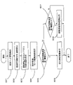
- FIG. 6 is a flow chart showing an overview of irradiation control in the laser irradiation apparatus of the first embodiment. Each step will be described in order below.
- Step S01 Detection of irradiation head acceleration, etc.>
- the irradiation head behavior calculator 130 of the control unit 100 detects the translational movement speed of the irradiation head 1 in the orthogonal three-axis directions and the angular velocity around the orthogonal three axes based on the output of the acceleration sensor 102 . After that, the process proceeds to step S02.
- Step S02 Irradiation Circle Moving Direction/Speed Calculation>
- the irradiation control section 110 of the control unit 100 calculates the moving direction and moving speed of the center of the irradiation circle C on the surface of the irradiation object O based on the behavior of the irradiation head 1 detected in step S01.
- the irradiation head 1 faces the surface to be irradiated so that the central axis of rotation of the wedge prism 20 and the normal direction of the surface to be irradiated are aligned, two axial directions perpendicular to the central axis of rotation of the wedge prism 20
- the moving direction and moving speed of the translational movement of the irradiation head 1 toward the center of the irradiation circle C substantially coincide with the moving direction and moving speed.
- the center of the irradiation circle C moves along the surface to be irradiated by a movement amount corresponding to the swing angle and the focal length. will do. After that, the process proceeds to step S03.
- FIG. 7 is a diagram showing an example of a movement mode of the irradiation circle on the surface of the object to be irradiated.
- the beam spot BS irradiation point
- the rotation center axis of the wedge prism 20 is aligned with the normal direction of the surface to be irradiated.
- the illustration is based on the premise that they match (the state in which the irradiation head 1 faces the surface to be irradiated). That is, the surface to be irradiated of the object to be irradiated O is a predetermined plane perpendicular to the central axis of rotation of the wedge prism 20 and including the focal position of the laser beam L.
- FIG. During actual construction, depending on the positional relationship between the irradiation head 1 and the irradiation object O, the surface to be irradiated and the rotation center axis of the wedge prism 20 may be inclined. may have an elliptical deformed shape.
- the focus state changes continuously (partially defocus state and defocus amount changes) depending on the position on the circumference of the ellipse.
- a defocused state in which the focal position of the laser beam L is shifted with respect to the surface to be irradiated may occur.
- Such a defocus state may be intentionally created to adjust the energy density in the beam spot BS.
- the effect of the present invention can be obtained by performing the irradiation control described below in the laser irradiation apparatus.
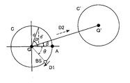
- the radius of the irradiation circle is d.
- ⁇ be the angle between a straight line Q′Q connecting the centers of the irradiation circles C before and after the movement and a straight line QA.
- ⁇ indicates the moving direction of the center of the irradiation circle C due to the behavior of the irradiation head 1 .
- the angular position ⁇ of the beam spot BS on the irradiation circle C corresponds to the angular position of the wedge prism 20 detected by the position sensor 101 .
- the irradiation control unit 110 stops the laser beam irradiation when, for example, ⁇ + ⁇ + ⁇ and ⁇ + ⁇ + ⁇ 2 ⁇ + ⁇ .
- the area where the irradiation of the laser light is stopped becomes the over-irradiation prevention area PA (see FIG. 9) referred to in the present invention. That is, in the over-irradiation prevention area PA, the traveling direction D1 (moving direction along the tangential line of the irradiation circle C) of the beam spot BS, which is the irradiation point, with respect to the surface (predetermined plane) of the irradiation object O is the scanning pattern.
- both ends of the trajectory of the irradiation circle C perpendicular to the movement direction on the plane of the center of the irradiation circle C and having a distance of d′ or more from the center of the irradiation circle along the radial direction of the irradiation circle C are irradiated with the laser. can be discontinued to suppress a local increase in the average number of irradiations. For example, as shown in FIG.
- d' should be set to approximately 12.2 mm in order to reduce the average number of times of irradiation to 4 or less.
- the traveling direction of the beam spot BS along the irradiation circle C accompanying the rotation of the wedge prism 20 forms an angle of a predetermined value with respect to the traveling direction (feeding direction) of the irradiation circle C.
- the following area area where the direction of travel of the beam spot BS and the direction of travel of the irradiation circle C are close to each other).
- the value of d' can be appropriately set according to irradiation conditions such as, for example, the properties of the object to be irradiated O, the purpose of laser processing, the laser output, the beam spot diameter, and the rotation speed of the wedge prism 20. .
- irradiation conditions such as, for example, the properties of the object to be irradiated O, the purpose of laser processing, the laser output, the beam spot diameter, and the rotation speed of the wedge prism 20.
- d' relatively small with respect to the irradiation circle diameter d in order to suppress an increase in the average number of irradiations.
- a state in which the average number of irradiation times is locally increased may be preferable in terms of efficiency, such as removal of deposits (for example, removal of relatively thick rust), so rough treatment such as the initial stage of irradiation (
- d' may be set relatively large, or d' may be made equal to d so that the irradiation of the laser beam is not stopped.
- d' may be set smaller than d to finish the surface smoothly.
- Step S04 Execution of irradiation control/motor drive control>
- the irradiation control unit 110 and the motor drive control unit 120 of the control unit 100 cause the laser oscillator 2 to generate a laser beam while rotating the motor 50 at a preset target rotation speed, and the irradiation head 1 emits a laser beam to the object to be irradiated.
- the irradiation of the laser beam L to O is performed.
- the irradiation control unit 110 controls the laser oscillator 2 so as to periodically stop the irradiation of the laser beam at the angular position of the wedge prism 20 determined in step S03. As a result, the laser beam L directed toward the over-irradiation prevention area PA is not emitted.
- the laser irradiation device takes an image of the surface of the irradiation target O using the camera 103 and measures the position of the surface of the irradiation target O using the laser scanner 104. Process monitoring can be performed. Based on the image captured by the camera 103, when the image processing unit 140 determines a predetermined surface state (for example, defective removal of the object to be removed, formation of an oxide film, etc.), it feeds back to the irradiation control unit 110, It can be configured to change irradiation parameters such as the output of laser light.
- a predetermined surface state for example, defective removal of the object to be removed, formation of an oxide film, etc.
- the focus state detection unit 150 detects a predetermined defocus state, or the inclination of the irradiation head 1 from the state facing the object O to be irradiated (a cause of periodic defocus state occurrence). ) is determined, the control unit 100 instructs the user (not shown) via the input/output device 200 to correct the relative position and orientation of the irradiation head 1 with respect to the object O to be irradiated, thereby defocusing the state. Give instructions to correct. After that, the process proceeds to step S05.
- Step S05 Judgment of irradiation circle moving speed (1)>
- the irradiation control section 110 of the control unit 100 compares the moving speed of the center of the irradiation circle C on the surface of the irradiation object O with a preset first threshold.
- the first threshold can be set in consideration of the moving speed at which the wrap rate at the front end of the irradiation circle C in the moving direction is 25%, for example. If the moving speed is equal to or less than the first threshold, the process proceeds to step S06; otherwise, the process proceeds to step S07.
- Step S06 Intermittent irradiation control execution>
- the irradiation control section 110 of the control unit 100 calculates the wrap rate at the front end portion in the moving direction of the irradiation circle, and performs intermittent irradiation control to intermittently stop the irradiation of the laser light according to the wrap rate.
- Table 1 shows an example of the relationship between the wrap rate and the laser beam emission state. As shown in Table 1, the frequency of stopping the emission of laser light (which can be rephrased as the ratio of the emission stop time to the total irradiation time (construction time), which is the sum of the emission time and the emission stop time), is the wrap rate.
- the irradiation is stopped while the wedge prism 20 rotates three times, and then the irradiation is continued while the wedge prism 20 rotates once, and the irradiation is stopped.
- the number of times (frequency) to do this is made greater than when the wrap rate is 50% or more and less than 75%.
- the irradiation circle C may be divided into a plurality of regions according to the angular positions around the center, and irradiation and irradiation stop may be sequentially switched for each region.
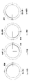
- FIG. 8 is a diagram showing an example of a mode of switching between irradiation and irradiation stop when an irradiation circle is divided and intermittent irradiation control is performed in the first embodiment.
- FIGS. 8(a) to 8(d) show an irradiation area and an irradiation stop area (irradiation restricted area) when the beam spot BS rotates around the irradiation circle C for each round.
- a portion where a beam spot BS is formed even in a region where irradiation is stopped will be referred to as a beam spot BS when the laser beam is emitted.
- the irradiation circle C is assumed to include an area that is not actually irradiated.
- the irradiation circle showing the irradiation pattern of one cycle is divided into four regions each with a center angle of 90°, for example, and each region is sequentially irradiated each time the beam spot BS rotates once. ing.
- the area other than the area where irradiation is performed is an irradiation stop area where irradiation is stopped. Note that the number of divisions of the irradiation circle C and the manner of division are not limited to this, and can be changed as appropriate. Further, the irradiation order and irradiation frequency of each region are not particularly limited.
- the above-described in-process monitoring can be performed when the irradiation is stopped in such intermittent irradiation control.
- irradiation stop at both ends of the irradiation area (over-irradiation prevention area PA) described in step S03 is also performed. After that, the series of processing ends (returns).
- Step S07 Judgment of irradiation circle moving speed (2)>
- the irradiation control section 110 of the control unit 100 compares the moving speed of the center of the irradiation circle on the surface of the irradiation object O with a preset second threshold (second threshold>first threshold).
- the second threshold can be set in consideration of the moving speed at which the wrap rate at the front end of the irradiation circle in the moving direction is 0%, for example. If the moving speed is equal to or higher than the second threshold, the process proceeds to step S08, otherwise the series of processes is terminated (returned).
- Step S08 Output of Movement Speed Suppression Warning>
- the control unit 100 outputs an alarm to a user (not shown) via the input/output device 200, indicating that the movement speed of the irradiation circle C on the surface of the object O is excessively high.
- the passage trajectory of the beam spot BS in at least a part of the irradiation circle C does not overlap (superimpose) with the passage trajectory during the previous round of the irradiation circle C, and there is no irradiation between the passage trajectories of each round. gap is formed (so-called tooth missing state).
- the warning can be issued by using, for example, an image display, a warning sound, vibration of equipment carried by the worker, or the like.
- the emission of the laser beam L may be stopped or the output of the laser beam L may be reduced. After that, the series of processing ends (returns).
- FIG. 9 is a diagram schematically showing an example of irradiation trajectories in the laser irradiation apparatuses of the comparative example and the first embodiment.
- FIGS. 9A and 9B show the irradiation trajectories of the comparative example and the first embodiment, respectively.
- the location where the over-irradiation prevention area PA is set is an area where the distance d' in the radial direction of the irradiation circle C orthogonal to the movement locus T of the center of the irradiation circle C is equal to or greater than a predetermined value. It has become. As a result, it is possible to prevent the formation of excessively deep groove-like irradiation traces and improve the surface quality.
- FIG. 10 is a diagram schematically showing the laser irradiation treated surface of the first embodiment.
- the base material e.g., steel
- the irradiation traces 310 are formed, for example, in an arc shape along the outer periphery of the irradiation circle C, and are arranged in plurality along the width direction of the central portion in the longitudinal direction.
- an irradiation start mark 311 formed by starting the irradiation of the laser beam L is formed.
- an irradiation stop mark 312 formed by stopping the irradiation of the laser beam L is formed. Both ends of the irradiation trace 310 are interrupted by an irradiation start trace 311 and an irradiation stop trace 312 and are not continuous with other irradiation traces 310 .
- the adjacent irradiation mark 310 overlaps with the overlap width W1 in the groove width direction.
- the irradiation mark 310 when the groove width of the irradiation mark 310 itself is W2, W1/W2 is the wrap ratio described above.
- the irradiation mark 310 When the rotation center axis of the wedge prism 20 is arranged along the normal direction of the surface to be irradiated, the irradiation mark 310 has an arc shape which is a part of a perfect circle. When the axis is inclined with respect to the normal direction, the irradiation mark 310 has a shape obtained by cutting out a part of an ellipse. A laser-irradiated surface having such irradiation traces 310 is also included in the technical scope of the present invention.
- An over-irradiation prevention area PA is formed in the vicinity of both ends of the irradiation circle movement range (places far from the movement trajectory of the center of the irradiation circle C) where the local increase in the number of irradiations in the irradiation circle C, which is the scanning pattern, tends to occur.
- the over-irradiation prevention area PA By setting the over-irradiation prevention area PA in an area where the angle formed by the advancing direction of the beam spot BS along the irradiation circle C with respect to the advancing direction of the irradiation circle is equal to or less than a predetermined value, the above effects can be appropriately obtained.
- the scanning pattern is an irradiation circle C, and the beam spot BS is moved along the irradiation circle C by setting the over-irradiation prevention area PA in an area separated by a predetermined value or more from the movement locus of the center of the irradiation circle C. In this case, the above effects can be effectively obtained by relatively simple control.
- Irradiation is intermittently stopped by setting an irradiation-restricted area in which irradiation is intermittently stopped as part of the irradiation circle C and sequentially changing the range occupied by the irradiation-restricted area within the irradiation circle C.
- the regions can be discretely distributed to reduce variations in surface quality after processing.
- the input/output device 200 When the moving speed of the irradiation circle C, which is the scanning pattern, with respect to the object to be irradiated is equal to or greater than the second threshold value, the input/output device 200 outputs an alarm, so that the moving speed of the irradiation circle C becomes excessively fast. Therefore, it is possible to prevent the formation of an unirradiated gap between the latest irradiation trajectory and the previous irradiation trajectory, thereby ensuring the surface quality. (9) By capturing an image of the irradiation object O with the camera 103 when the irradiation of the laser light is temporarily stopped, the surface state of the irradiation object O can be obtained by in-process monitoring, and the irradiation conditions can be set.
- the laser scanner 104 detects the focus state of the laser beam L on the surface of the object to be irradiated O, and prompts the user to correct the defocus state when the defocus state is detected. It is possible to improve the construction quality by improving the focus state at the time of irradiation.
- a second embodiment of a laser irradiation apparatus and a laser irradiation method to which the present invention is applied will be described.
- the behavior (velocity, angular velocity, etc.) of the irradiation head 1 is not detected, and when the beam spot BS is within a predetermined angular range on the irradiation circle C, the laser beam is emitted at a constant angle. Irradiation is stopped periodically at intervals.
- FIG. 11 is a diagram showing an example of the distribution of the irradiation range and the irradiation stop range on the irradiation circle in the laser irradiation device of the second embodiment.
- Irradiation stop ranges (over-irradiation prevention ranges) in which the emission of laser light is stopped are set in advance at two points on the circumference of the irradiation circle C. As shown in FIG. Two irradiation stop ranges are set, for example, such that the angular positions viewed from the center of the irradiation circle C are shifted by 180°.
- the irradiation control unit 110 gives a command to the laser oscillator 2 to stop generation of laser light.
- the width of the irradiation stop range (for example, the angle range when viewed from the center of the irradiation circle C) and the position where the irradiation stop range is set may be set by the user or the like as appropriate.
- the position of the irradiation stop range can be set, or the degree of surface roughness required for construction quality can be set. can be used to set the width of the irradiation stop range.
- the moving direction of the irradiation head 1 (the feeding direction of the irradiation circle C) during construction is predetermined
- simple detection of the behavior of the irradiation head 1 is not performed.
- An increase in the number of local irradiations can be suppressed by the device configuration and control.
- a detection means is provided for detecting that the feed direction of the irradiation circle C is different from a predetermined direction, and an alarm or the like is output when the feed direction is different from the predetermined direction. may be configured.
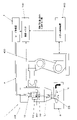
- FIG. 12 is a diagram schematically showing the configuration of the laser irradiation device of the third embodiment.
- the irradiation head 1 is held and moved by the robot 400 .
- the robot 400 holds the irradiation head 1 and moves the irradiation head 100 relative to the irradiation target O so that the irradiation circle C moves on the surface of the irradiation target O according to a predetermined irradiation path. be.
- the robot 400 has a robot controller 410 .
- the robot control device 410 comprehensively controls the actuators (motors) and the like provided on each axis of the robot 400 .
- the robot control device 410 includes information processing means such as a CPU, storage means such as a RAM and a ROM, an input/output interface, and a bus connecting these.
- the robot control device 410 holds information about previously taught irradiation paths, and gives commands to the actuators of the robot 400 so that the irradiation head 1 moves along the machining paths at a predetermined feed rate.
- the robot control device 410 provides the control unit 100 of the laser irradiation device with information on the moving direction and moving speed of the irradiation circle C with respect to the object O to be irradiated.
- the irradiation control section 110 of the control unit 100 controls the over-irradiation prevention area and the irradiation restriction area substantially in the same manner as in the first embodiment, based on the information about the movement direction and movement speed of the irradiation circle C obtained from the robot control device 410. settings.
- the robot control device 410 provides the control unit 100 of the laser irradiation device with information on the moving direction and moving speed of the irradiation circle C with respect to the object O to be irradiated.
- the irradiation control section 110 of the control unit 100 controls the over-irradiation prevention area and the irradiation restriction area substantially in the same manner as in the first embodiment, based on the information about the movement direction and movement speed of the irradiation circle C obtained from the
- FIG. 14 is a diagram schematically showing the configuration of the laser irradiation device of the fourth embodiment.
- a scan pattern irradiation circle C as an example is formed by the galvanometer scanner 520 .
- the galvanometer scanner 500 has a laser oscillator (not shown) and mirrors 510 and 520 that sequentially reflect the laser beam L emitted from the condensing optical system.
- the mirrors 510 and 520 are supported so as to be swingable about predetermined rotation center axes, and are driven in swinging directions by actuators 511 and 521, respectively.
- the rotation central axes of the mirrors 510 and 520 are arranged at twisted positions, and by swinging the mirror 510, the beam spot BS is projected on a predetermined plane (typically, the surface to be irradiated of the object O to be irradiated). It can be displaced in a first direction, and by oscillating the mirror 520, the beam spot BS can be displaced in a second direction (typically orthogonal) different from the first direction on the plane. can be done.
- the actuators 511 and 521 are controlled by a control device (not shown), and the mirrors 510 and 520 are synchronously oscillated in a predetermined pattern so that the beam spot BS can be moved in any direction on the plane. can be moved to Moreover, even when the galvanometer scanner 500 is stationary with respect to the object O to be irradiated, the irradiation circle C can be moved on the surface to be irradiated.
- an irradiation restriction area PA is set in an area separated by a predetermined value or more in the radial direction of the irradiation circle C from the movement direction of the center of the irradiation circle C. is doing.
- the shape of the scanning pattern and the setting of the irradiation restriction area PA are not limited to this, and can be changed as appropriate.
- the angle formed by the movement direction of the beam spot with respect to the movement direction of the scanning pattern with respect to the irradiation object O is a predetermined value or less, the emission of the laser beam L can be stopped or the intensity can be reduced.
- the fourth embodiment described above even when the scan pattern is formed by the galvanometer scanner 500, the same effects as those of the first embodiment described above can be obtained.
- the present invention is not limited to the embodiments described above, and various modifications and changes are possible, and these are also within the technical scope of the present invention.
- the configurations of the laser irradiation device, the laser irradiation method, and the laser irradiation treatment surface are not limited to the configurations of the above-described embodiments, and can be changed as appropriate.
- the type of object to be irradiated, the purpose of laser irradiation processing, irradiation conditions, and the like can be changed as appropriate.
- the laser beam irradiation is temporarily stopped in the over-irradiation prevention region and the irradiation suppression region. good too.
- the intensity of the laser light may be gradually changed continuously or stepwise.
- a rotating wedge prism is used to form an irradiation circle, which is a circumferential scanning pattern.
- the laser beam may be irradiated in a state of being rotated (so-called weaving in which the amount of shift is changed periodically) while being shifted (decentered) in parallel.
- the shape of the scanning pattern is not limited to a circle, and may be, for example, a polygon or other shapes.
- the configuration of the optical system that forms the scanning pattern is not particularly limited, and for example, a galvanometer scanner or polygon mirror may be used alone or in combination with other techniques.
- the method of detecting the moving direction and moving speed of the scanning pattern on the surface of the irradiation object is not limited to the configuration of each embodiment and can be changed as appropriate.
- the method of performing in-process monitoring when irradiation is stopped and the events to be monitored are not limited to those described in each embodiment and can be changed as appropriate.
Landscapes
- Physics & Mathematics (AREA)
- Optics & Photonics (AREA)
- Engineering & Computer Science (AREA)
- Plasma & Fusion (AREA)
- Mechanical Engineering (AREA)
- Robotics (AREA)
- Laser Beam Processing (AREA)
Priority Applications (2)
| Application Number | Priority Date | Filing Date | Title |
|---|---|---|---|
| EP22815994.3A EP4349522A4 (en) | 2021-06-03 | 2022-05-27 | LASER RADIATION DEVICE AND METHOD AND SURFACE TREATED BY LASER RADIATION |
| US18/522,873 US20240091880A1 (en) | 2021-06-03 | 2023-11-29 | Laser irradiation apparatus, laser irradiation method and laser irradiation processed surface |
Applications Claiming Priority (2)
| Application Number | Priority Date | Filing Date | Title |
|---|---|---|---|
| JP2021093955A JP7818793B2 (ja) | 2021-06-03 | 2021-06-03 | レーザ照射装置、レーザ照射方法、及び、レーザ照射処理表面 |
| JP2021-093955 | 2021-06-03 |
Related Child Applications (1)
| Application Number | Title | Priority Date | Filing Date |
|---|---|---|---|
| US18/522,873 Continuation US20240091880A1 (en) | 2021-06-03 | 2023-11-29 | Laser irradiation apparatus, laser irradiation method and laser irradiation processed surface |
Publications (1)
| Publication Number | Publication Date |
|---|---|
| WO2022255244A1 true WO2022255244A1 (ja) | 2022-12-08 |
Family
ID=84324082
Family Applications (1)
| Application Number | Title | Priority Date | Filing Date |
|---|---|---|---|
| PCT/JP2022/021722 Ceased WO2022255244A1 (ja) | 2021-06-03 | 2022-05-27 | レーザ照射装置、レーザ照射方法、及び、レーザ照射処理表面 |
Country Status (4)
| Country | Link |
|---|---|
| US (1) | US20240091880A1 (https=) |
| EP (1) | EP4349522A4 (https=) |
| JP (2) | JP7818793B2 (https=) |
| WO (1) | WO2022255244A1 (https=) |
Cited By (1)
| Publication number | Priority date | Publication date | Assignee | Title |
|---|---|---|---|---|
| EP4556153A1 (en) * | 2023-11-16 | 2025-05-21 | Samsung SDI Co., Ltd. | Welding apparatus and method with horizontally irradiated laser |
Citations (5)
| Publication number | Priority date | Publication date | Assignee | Title |
|---|---|---|---|---|
| JP2002273585A (ja) * | 2001-03-16 | 2002-09-25 | Ricoh Microelectronics Co Ltd | ビーム加工方法及びその装置、並びにタッチパネル基板の製造方法 |
| WO2013133415A1 (ja) | 2012-03-09 | 2013-09-12 | 株式会社トヨコー | レーザー照射装置、レーザー照射システム及び塗膜又は付着物除去方法 |
| JP2019141868A (ja) * | 2018-02-19 | 2019-08-29 | ファナック株式会社 | レーザ加工装置 |
| JP2021049535A (ja) * | 2019-09-24 | 2021-04-01 | 株式会社フジクラ | レーザ照射装置及び樹脂成形体の製造方法 |
| WO2021200667A1 (ja) * | 2020-03-31 | 2021-10-07 | 前田建設工業株式会社 | コンクリートの表面処理方法、及び、レーザ処理済みコンクリート表面 |
Family Cites Families (12)
| Publication number | Priority date | Publication date | Assignee | Title |
|---|---|---|---|---|
| DE4200632C2 (de) * | 1992-01-13 | 1995-09-21 | Maho Ag | Verfahren und Vorrichtung zum Bearbeiten von Werkstücken mittels der von einem Laser emittierten Laserstrahlung |
| JP2000141070A (ja) | 1998-11-05 | 2000-05-23 | Amada Eng Center Co Ltd | レーザ加工ヘッド |
| JP5028722B2 (ja) | 2001-07-31 | 2012-09-19 | 三菱電機株式会社 | レーザ加工方法及びレーザ加工機 |
| DE10217200A1 (de) | 2002-04-18 | 2003-10-30 | Winter Pipeline Gmbh | Verfahren und Vorrichtung zur Materialbearbeitung mit Laserstrahlen |
| JP4973982B2 (ja) | 2007-01-10 | 2012-07-11 | 株式会社安川電機 | ガルバノスキャナシステムおよび制御方法 |
| US8160113B2 (en) * | 2009-07-21 | 2012-04-17 | Mobius Photonics, Inc. | Tailored pulse burst |
| US9067278B2 (en) | 2013-03-29 | 2015-06-30 | Photon Automation, Inc. | Pulse spread laser |
| CN105555465B (zh) | 2014-02-25 | 2017-05-10 | 松下知识产权经营株式会社 | 激光焊接方法 |
| JP6036737B2 (ja) | 2014-03-31 | 2016-11-30 | ブラザー工業株式会社 | レーザ加工装置、レーザ加工方法及びプログラム |
| JP6948888B2 (ja) | 2017-08-31 | 2021-10-13 | 株式会社神戸製鋼所 | 接合体の製造方法及び接合体の製造装置 |
| JP6638032B1 (ja) | 2018-07-31 | 2020-01-29 | 株式会社アマダホールディングス | レーザ加工機及びレーザ加工方法 |
| CN111001940A (zh) | 2019-12-24 | 2020-04-14 | 武汉翔明激光科技有限公司 | 一种基于激光与振镜联动控制的激光均匀清洗方法 |
-
2021
- 2021-06-03 JP JP2021093955A patent/JP7818793B2/ja active Active
-
2022
- 2022-05-27 WO PCT/JP2022/021722 patent/WO2022255244A1/ja not_active Ceased
- 2022-05-27 EP EP22815994.3A patent/EP4349522A4/en active Pending
-
2023
- 2023-11-29 US US18/522,873 patent/US20240091880A1/en active Pending
-
2025
- 2025-12-23 JP JP2025277550A patent/JP2026040592A/ja active Pending
Patent Citations (5)
| Publication number | Priority date | Publication date | Assignee | Title |
|---|---|---|---|---|
| JP2002273585A (ja) * | 2001-03-16 | 2002-09-25 | Ricoh Microelectronics Co Ltd | ビーム加工方法及びその装置、並びにタッチパネル基板の製造方法 |
| WO2013133415A1 (ja) | 2012-03-09 | 2013-09-12 | 株式会社トヨコー | レーザー照射装置、レーザー照射システム及び塗膜又は付着物除去方法 |
| JP2019141868A (ja) * | 2018-02-19 | 2019-08-29 | ファナック株式会社 | レーザ加工装置 |
| JP2021049535A (ja) * | 2019-09-24 | 2021-04-01 | 株式会社フジクラ | レーザ照射装置及び樹脂成形体の製造方法 |
| WO2021200667A1 (ja) * | 2020-03-31 | 2021-10-07 | 前田建設工業株式会社 | コンクリートの表面処理方法、及び、レーザ処理済みコンクリート表面 |
Non-Patent Citations (1)
| Title |
|---|
| See also references of EP4349522A4 |
Cited By (1)
| Publication number | Priority date | Publication date | Assignee | Title |
|---|---|---|---|---|
| EP4556153A1 (en) * | 2023-11-16 | 2025-05-21 | Samsung SDI Co., Ltd. | Welding apparatus and method with horizontally irradiated laser |
Also Published As
| Publication number | Publication date |
|---|---|
| EP4349522A1 (en) | 2024-04-10 |
| EP4349522A4 (en) | 2025-07-09 |
| JP2026040592A (ja) | 2026-03-09 |
| JP2022185982A (ja) | 2022-12-15 |
| US20240091880A1 (en) | 2024-03-21 |
| JP7818793B2 (ja) | 2026-02-24 |
Similar Documents
| Publication | Publication Date | Title |
|---|---|---|
| EP3807041B1 (en) | System and method for monitoring and/or controlling wobble-processing using inline coherent imaging (ici) | |
| EP3310518B1 (en) | Laser welding system with a laser welding head having with dual movable mirrors providing beam movement with limited field of view | |
| JP6740267B2 (ja) | レーザ加工装置 | |
| KR101718265B1 (ko) | 가공장치 및 가공방법 | |
| JPWO2020095454A1 (ja) | 積層造形装置 | |
| JP2026040592A (ja) | レーザ照射装置、レーザ照射方法、及び、レーザ照射処理表面 | |
| WO2001072465A1 (en) | Laser machining apparatus | |
| TW201433394A (zh) | 加工裝置及加工方法 | |
| JP5446334B2 (ja) | レーザ溶接装置、およびレーザ溶接方法 | |
| CN114466723A (zh) | 激光照射装置 | |
| JP5577927B2 (ja) | レーザー加工検知システム | |
| JP6951040B2 (ja) | レーザ加工装置及びレーザ加工方法 | |
| JP2011143420A (ja) | レーザー式加工装置及び加工方法 | |
| JP2581574B2 (ja) | レ−ザ加工方法およびその装置 | |
| US20220395925A1 (en) | Method for laser machining a workpiece and associated laser machining system | |
| JP6643837B2 (ja) | レーザー加工装置 | |
| JP2020157332A (ja) | レーザ照射装置 | |
| JP2014223672A (ja) | 回転体のレーザ加工方法及び加工装置 | |
| RU2795069C2 (ru) | Системы и способы контроля и/или управления обработкой с вобуляцией с использованием встроенной когерентной визуализации (ici) | |
| JPH10202385A (ja) | レーザ加工装置 | |
| JP2008062285A (ja) | レーザによる溝加工方法 | |
| JP7185436B2 (ja) | レーザ加工方法 | |
| JP2023050208A (ja) | レーザ照射装置 | |
| WO2023085243A1 (ja) | 表面処理方法 | |
| JP2020127952A (ja) | レーザ加工装置およびレーザ加工方法 |
Legal Events
| Date | Code | Title | Description |
|---|---|---|---|
| 121 | Ep: the epo has been informed by wipo that ep was designated in this application |
Ref document number: 22815994 Country of ref document: EP Kind code of ref document: A1 |
|
| WWE | Wipo information: entry into national phase |
Ref document number: 2022815994 Country of ref document: EP |
|
| NENP | Non-entry into the national phase |
Ref country code: DE |
|
| ENP | Entry into the national phase |
Ref document number: 2022815994 Country of ref document: EP Effective date: 20240103 |