WO2022254546A1 - シート材容器 - Google Patents
シート材容器 Download PDFInfo
- Publication number
- WO2022254546A1 WO2022254546A1 PCT/JP2021/020732 JP2021020732W WO2022254546A1 WO 2022254546 A1 WO2022254546 A1 WO 2022254546A1 JP 2021020732 W JP2021020732 W JP 2021020732W WO 2022254546 A1 WO2022254546 A1 WO 2022254546A1
- Authority
- WO
- WIPO (PCT)
- Prior art keywords
- sheet material
- protective cover
- material container
- filling
- container
- Prior art date
- Legal status (The legal status is an assumption and is not a legal conclusion. Google has not performed a legal analysis and makes no representation as to the accuracy of the status listed.)
- Ceased
Links
Images


Classifications
-
- B—PERFORMING OPERATIONS; TRANSPORTING
- B65—CONVEYING; PACKING; STORING; HANDLING THIN OR FILAMENTARY MATERIAL
- B65D—CONTAINERS FOR STORAGE OR TRANSPORT OF ARTICLES OR MATERIALS, e.g. BAGS, BARRELS, BOTTLES, BOXES, CANS, CARTONS, CRATES, DRUMS, JARS, TANKS, HOPPERS, FORWARDING CONTAINERS; ACCESSORIES, CLOSURES, OR FITTINGS THEREFOR; PACKAGING ELEMENTS; PACKAGES
- B65D75/00—Packages comprising articles or materials partially or wholly enclosed in strips, sheets, blanks, tubes or webs of flexible sheet material, e.g. in folded wrappers
- B65D75/008—Standing pouches, i.e. "Standbeutel"
-
- B—PERFORMING OPERATIONS; TRANSPORTING
- B65—CONVEYING; PACKING; STORING; HANDLING THIN OR FILAMENTARY MATERIAL
- B65D—CONTAINERS FOR STORAGE OR TRANSPORT OF ARTICLES OR MATERIALS, e.g. BAGS, BARRELS, BOTTLES, BOXES, CANS, CARTONS, CRATES, DRUMS, JARS, TANKS, HOPPERS, FORWARDING CONTAINERS; ACCESSORIES, CLOSURES, OR FITTINGS THEREFOR; PACKAGING ELEMENTS; PACKAGES
- B65D75/00—Packages comprising articles or materials partially or wholly enclosed in strips, sheets, blanks, tubes or webs of flexible sheet material, e.g. in folded wrappers
- B65D75/38—Articles or materials enclosed in two or more wrappers disposed one inside the other
-
- B—PERFORMING OPERATIONS; TRANSPORTING
- B05—SPRAYING OR ATOMISING IN GENERAL; APPLYING FLUENT MATERIALS TO SURFACES, IN GENERAL
- B05B—SPRAYING APPARATUS; ATOMISING APPARATUS; NOZZLES
- B05B11/00—Single-unit hand-held apparatus in which flow of contents is produced by the muscular force of the operator at the moment of use
- B05B11/01—Single-unit hand-held apparatus in which flow of contents is produced by the muscular force of the operator at the moment of use characterised by the means producing the flow
- B05B11/02—Membranes or pistons acting on the contents inside the container, e.g. follower pistons
- B05B11/026—Membranes separating the content remaining in the container from the atmospheric air to compensate underpressure inside the container
-
- B—PERFORMING OPERATIONS; TRANSPORTING
- B32—LAYERED PRODUCTS
- B32B—LAYERED PRODUCTS, i.e. PRODUCTS BUILT-UP OF STRATA OF FLAT OR NON-FLAT, e.g. CELLULAR OR HONEYCOMB, FORM
- B32B7/00—Layered products characterised by the relation between layers; Layered products characterised by the relative orientation of features between layers, or by the relative values of a measurable parameter between layers, i.e. products comprising layers having different physical, chemical or physicochemical properties; Layered products characterised by the interconnection of layers
- B32B7/04—Interconnection of layers
- B32B7/05—Interconnection of layers the layers not being connected over the whole surface, e.g. discontinuous connection or patterned connection
-
- B—PERFORMING OPERATIONS; TRANSPORTING
- B65—CONVEYING; PACKING; STORING; HANDLING THIN OR FILAMENTARY MATERIAL
- B65D—CONTAINERS FOR STORAGE OR TRANSPORT OF ARTICLES OR MATERIALS, e.g. BAGS, BARRELS, BOTTLES, BOXES, CANS, CARTONS, CRATES, DRUMS, JARS, TANKS, HOPPERS, FORWARDING CONTAINERS; ACCESSORIES, CLOSURES, OR FITTINGS THEREFOR; PACKAGING ELEMENTS; PACKAGES
- B65D11/00—Containers having bodies formed by interconnecting or uniting two or more rigid, or substantially rigid, components made wholly or mainly of plastics material
- B65D11/20—Details of walls made of plastics material
- B65D11/22—Reinforcing for strengthening parts of members
-
- B—PERFORMING OPERATIONS; TRANSPORTING
- B65—CONVEYING; PACKING; STORING; HANDLING THIN OR FILAMENTARY MATERIAL
- B65D—CONTAINERS FOR STORAGE OR TRANSPORT OF ARTICLES OR MATERIALS, e.g. BAGS, BARRELS, BOTTLES, BOXES, CANS, CARTONS, CRATES, DRUMS, JARS, TANKS, HOPPERS, FORWARDING CONTAINERS; ACCESSORIES, CLOSURES, OR FITTINGS THEREFOR; PACKAGING ELEMENTS; PACKAGES
- B65D33/00—Details of, or accessories for, sacks or bags
- B65D33/02—Local reinforcements or stiffening inserts, e.g. wires, strings, strips or frames
-
- B—PERFORMING OPERATIONS; TRANSPORTING
- B65—CONVEYING; PACKING; STORING; HANDLING THIN OR FILAMENTARY MATERIAL
- B65D—CONTAINERS FOR STORAGE OR TRANSPORT OF ARTICLES OR MATERIALS, e.g. BAGS, BARRELS, BOTTLES, BOXES, CANS, CARTONS, CRATES, DRUMS, JARS, TANKS, HOPPERS, FORWARDING CONTAINERS; ACCESSORIES, CLOSURES, OR FITTINGS THEREFOR; PACKAGING ELEMENTS; PACKAGES
- B65D65/00—Wrappers or flexible covers; Packaging materials of special type or form
- B65D65/38—Packaging materials of special type or form
- B65D65/40—Applications of laminates for particular packaging purposes
-
- B—PERFORMING OPERATIONS; TRANSPORTING
- B65—CONVEYING; PACKING; STORING; HANDLING THIN OR FILAMENTARY MATERIAL
- B65D—CONTAINERS FOR STORAGE OR TRANSPORT OF ARTICLES OR MATERIALS, e.g. BAGS, BARRELS, BOTTLES, BOXES, CANS, CARTONS, CRATES, DRUMS, JARS, TANKS, HOPPERS, FORWARDING CONTAINERS; ACCESSORIES, CLOSURES, OR FITTINGS THEREFOR; PACKAGING ELEMENTS; PACKAGES
- B65D75/00—Packages comprising articles or materials partially or wholly enclosed in strips, sheets, blanks, tubes or webs of flexible sheet material, e.g. in folded wrappers
- B65D75/52—Details
- B65D75/525—External rigid or semi-rigid supports
-
- B—PERFORMING OPERATIONS; TRANSPORTING
- B65—CONVEYING; PACKING; STORING; HANDLING THIN OR FILAMENTARY MATERIAL
- B65D—CONTAINERS FOR STORAGE OR TRANSPORT OF ARTICLES OR MATERIALS, e.g. BAGS, BARRELS, BOTTLES, BOXES, CANS, CARTONS, CRATES, DRUMS, JARS, TANKS, HOPPERS, FORWARDING CONTAINERS; ACCESSORIES, CLOSURES, OR FITTINGS THEREFOR; PACKAGING ELEMENTS; PACKAGES
- B65D75/00—Packages comprising articles or materials partially or wholly enclosed in strips, sheets, blanks, tubes or webs of flexible sheet material, e.g. in folded wrappers
- B65D75/52—Details
- B65D75/58—Opening or contents-removing devices added or incorporated during package manufacture
- B65D75/5861—Spouts
- B65D75/5872—Non-integral spouts
- B65D75/5877—Non-integral spouts connected to a planar surface of the package wall
-
- B—PERFORMING OPERATIONS; TRANSPORTING
- B65—CONVEYING; PACKING; STORING; HANDLING THIN OR FILAMENTARY MATERIAL
- B65D—CONTAINERS FOR STORAGE OR TRANSPORT OF ARTICLES OR MATERIALS, e.g. BAGS, BARRELS, BOTTLES, BOXES, CANS, CARTONS, CRATES, DRUMS, JARS, TANKS, HOPPERS, FORWARDING CONTAINERS; ACCESSORIES, CLOSURES, OR FITTINGS THEREFOR; PACKAGING ELEMENTS; PACKAGES
- B65D75/00—Packages comprising articles or materials partially or wholly enclosed in strips, sheets, blanks, tubes or webs of flexible sheet material, e.g. in folded wrappers
- B65D75/52—Details
- B65D75/58—Opening or contents-removing devices added or incorporated during package manufacture
- B65D75/5861—Spouts
- B65D75/5872—Non-integral spouts
- B65D75/5883—Non-integral spouts connected to the package at the sealed junction of two package walls
-
- B—PERFORMING OPERATIONS; TRANSPORTING
- B05—SPRAYING OR ATOMISING IN GENERAL; APPLYING FLUENT MATERIALS TO SURFACES, IN GENERAL
- B05B—SPRAYING APPARATUS; ATOMISING APPARATUS; NOZZLES
- B05B11/00—Single-unit hand-held apparatus in which flow of contents is produced by the muscular force of the operator at the moment of use
- B05B11/01—Single-unit hand-held apparatus in which flow of contents is produced by the muscular force of the operator at the moment of use characterised by the means producing the flow
- B05B11/10—Pump arrangements for transferring the contents from the container to a pump chamber by a sucking effect and forcing the contents out through the dispensing nozzle
- B05B11/1042—Components or details
- B05B11/1043—Sealing or attachment arrangements between pump and container
- B05B11/1046—Sealing or attachment arrangements between pump and container the pump chamber being arranged substantially coaxially to the neck of the container
- B05B11/1047—Sealing or attachment arrangements between pump and container the pump chamber being arranged substantially coaxially to the neck of the container the pump being preassembled as an independent unit before being mounted on the container
-
- B—PERFORMING OPERATIONS; TRANSPORTING
- B05—SPRAYING OR ATOMISING IN GENERAL; APPLYING FLUENT MATERIALS TO SURFACES, IN GENERAL
- B05B—SPRAYING APPARATUS; ATOMISING APPARATUS; NOZZLES
- B05B11/00—Single-unit hand-held apparatus in which flow of contents is produced by the muscular force of the operator at the moment of use
- B05B11/01—Single-unit hand-held apparatus in which flow of contents is produced by the muscular force of the operator at the moment of use characterised by the means producing the flow
- B05B11/10—Pump arrangements for transferring the contents from the container to a pump chamber by a sucking effect and forcing the contents out through the dispensing nozzle
- B05B11/1042—Components or details
- B05B11/1059—Means for locking a pump or its actuation means in a fixed position
- B05B11/106—Means for locking a pump or its actuation means in a fixed position in a retracted position, e.g. in an end-of-dispensing-stroke position
-
- B—PERFORMING OPERATIONS; TRANSPORTING
- B32—LAYERED PRODUCTS
- B32B—LAYERED PRODUCTS, i.e. PRODUCTS BUILT-UP OF STRATA OF FLAT OR NON-FLAT, e.g. CELLULAR OR HONEYCOMB, FORM
- B32B2439/00—Containers; Receptacles
- B32B2439/40—Closed containers
-
- B—PERFORMING OPERATIONS; TRANSPORTING
- B65—CONVEYING; PACKING; STORING; HANDLING THIN OR FILAMENTARY MATERIAL
- B65D—CONTAINERS FOR STORAGE OR TRANSPORT OF ARTICLES OR MATERIALS, e.g. BAGS, BARRELS, BOTTLES, BOXES, CANS, CARTONS, CRATES, DRUMS, JARS, TANKS, HOPPERS, FORWARDING CONTAINERS; ACCESSORIES, CLOSURES, OR FITTINGS THEREFOR; PACKAGING ELEMENTS; PACKAGES
- B65D2565/00—Wrappers or flexible covers; Packaging materials of special type or form
- B65D2565/38—Packaging materials of special type or form
- B65D2565/381—Details of packaging materials of special type or form
- B65D2565/385—Details of packaging materials of special type or form especially suited for or with means facilitating recycling
-
- Y—GENERAL TAGGING OF NEW TECHNOLOGICAL DEVELOPMENTS; GENERAL TAGGING OF CROSS-SECTIONAL TECHNOLOGIES SPANNING OVER SEVERAL SECTIONS OF THE IPC; TECHNICAL SUBJECTS COVERED BY FORMER USPC CROSS-REFERENCE ART COLLECTIONS [XRACs] AND DIGESTS
- Y02—TECHNOLOGIES OR APPLICATIONS FOR MITIGATION OR ADAPTATION AGAINST CLIMATE CHANGE
- Y02W—CLIMATE CHANGE MITIGATION TECHNOLOGIES RELATED TO WASTEWATER TREATMENT OR WASTE MANAGEMENT
- Y02W30/00—Technologies for solid waste management
- Y02W30/50—Reuse, recycling or recovery technologies
- Y02W30/80—Packaging reuse or recycling, e.g. of multilayer packaging
Definitions
- the present invention relates to a sheet material container and a recycling method.
- Patent Document 1 A sheet material container having a structure in which a plurality of films are laminated and a filler such as air is enclosed between the layers is described in Patent Document 1, for example.
- the sheet material container of Patent Document 1 includes a container having a storage area for storing contents, a bag covering the container, and a bag-constituting sheet material forming the bag.
- the bag-constituting sheet material includes a joint portion where a plurality of film layers are joined together and a non-joint portion where the plurality of film layers are partially unjoined, and the plurality of films in the non-joint portion A filler is enclosed between the layers to form a filler.
- Prior art documents Patent Document 1 Japanese Patent No. 6193535 Japanese Patent No. 6193535
- the present invention is a sheet material container constructed with one or more sheet materials including a body forming sheet material having an outer film layer and an inner film layer laminated to each other, the container containing a content.
- An accommodation area and a container body that is configured by the main body-constituting sheet material and surrounds the accommodation area, and the main body-constituting sheet material is formed by joining the outer film layer and the inner film layer. and a non-bonded portion in which the outer film layer and the inner film layer are partially unbonded, and the outer film layer and the inner film layer are separated from each other at the non-bonded portion.
- the sheet material container has a filling portion in which a filler is enclosed between layers, and further relates to a sheet material container provided with a protective cover made of a film and covering the outer surface of the container body.
- the present invention is a method for recycling the sheet material container of the present invention, comprising: separating the protective cover from the plurality of sheet materials; cleaning the plurality of sheet materials;
- the present invention relates to a recycling method comprising a step of producing recycled resin using a plurality of sheet materials, a step of washing the protective cover, and a step of producing recycled resin using the washed protective cover.
- FIG. 1 is a perspective view of a sheet material container according to a first embodiment
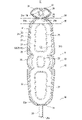
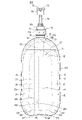
- FIG. 1 is a front view of a sheet material container according to a first embodiment
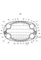
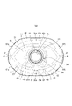
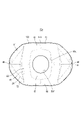
- FIG. It is a bottom view of a sheet material container concerning a 1st embodiment.
- FIG. 3 is a cross-sectional view taken along line AA of FIG. 2;
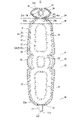
- FIG. 4 is an exploded perspective view showing an outer film layer and an inner film layer of the main body-constituting sheet material;
- FIG. 4 is an exploded perspective view showing an inner bag-constituting sheet material and a main body-constituting sheet material;
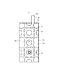
- FIG. 4 is a plan view showing a container-constituting sheet material having an inner bag-constituting sheet material and a main body-constituting sheet material that are laminated to each other;
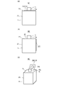
- 1 is a perspective view showing a sheet material container according to a first embodiment, showing a state before enclosing a filler.
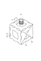
- FIG. 2 is a perspective view showing the sheet material container according to the first embodiment, showing a state in which a cap portion is attached after enclosing a filler.
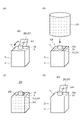
- FIG. 11 is a plan view showing a container-constituting sheet material used for manufacturing the sheet material container according to the second embodiment; 11(a) to 11(c) are schematic perspective views showing a series of steps for manufacturing a sheet material container according to the second embodiment, and FIG. 11(d) is a sheet material container according to the second embodiment.
- FIG. 4 is a schematic cross-sectional view showing a state in which a protective cover is removed from the material container;
- FIG. 12(a) is a schematic side view of the sheet material container according to the second embodiment, showing a state before the protective cover is attached, and
- FIG. 12(b) is a modified example 1 of the second embodiment.
- FIG. 12(c) is a schematic side view of the sheet material container according to Modification 2 of the second embodiment, and shows a state before the protective cover is attached.
- FIG. It is a figure and shows the state before attachment of a protective cover.
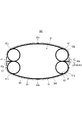
- 13(a) and 13(b) are plan views for explaining the operation of discharging the filling material from the filling portion of the sheet material container according to the second embodiment.
- FIG. 11 is a plan view showing a container-constituting sheet material used for manufacturing a sheet material container according to Modification 3 of the second embodiment; 15(a) and 15(b) are diagrams showing steps of manufacturing a sheet material container according to Modification 3 of the second embodiment.
- FIG. 11 is a plan view showing a container-constituting sheet material used for manufacturing a sheet material container according to Modification 4 of the second embodiment;
- FIG. 10 is a plan view showing a container-constituting sheet material used for manufacturing a sheet material container according to Modification Example 5 of the second embodiment.
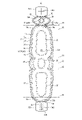
- FIG. 11 is a plan view of the sheet material container according to the third embodiment, showing a state in which the cap portion is not attached. It is a front view of the sheet material container which concerns on 3rd Embodiment. It is a bottom view of the sheet material container which concerns on 3rd Embodiment.
- FIG. 11 is a perspective view showing a sheet material container according to a fourth embodiment, showing a state before enclosing a filler.
- FIG. 11 is a side view showing a sheet material container according to a fifth embodiment
- FIG. 20 is a side view showing the sheet material container according to the fifth embodiment, showing a state where the protective cover is not attached.
- FIG. 11 is a plan view showing a container-constituting sheet material used for manufacturing a sheet material container according to a fifth embodiment
- FIG. 12 is a perspective view of the sheet material container according to the fifth embodiment, showing a state in which the protective cover and the cap portion are not attached.
- FIG. 11 is a schematic cross-sectional plan view of a sheet material container according to a sixth embodiment
- FIG. 11 is a schematic cross-sectional plan view of a sheet material container according to a seventh embodiment;
- FIG. 21 is a side view of a sheet material container according to an eighth embodiment
- FIG. 21 is a perspective view of a sheet material container according to an eighth embodiment
- FIG. 11 is a schematic side cross-sectional view showing a portion of a sheet material container according to an eighth embodiment
- the sheet material container of Patent Document 1 still has room for improvement in terms of structural strength.
- the present invention relates to a sheet material container with a structure capable of achieving better structural strength, and a recycling method thereof.
- the sheet material container 200 includes a main body forming sheet material 21 (see FIG. 5) having an outer film layer 22 and an inner film layer 23 laminated to each other. It is constructed with one or more sheets of material.
- the sheet material container 200 includes an accommodation area 17 that accommodates a content 18 , and a container body 20 that is composed of a body-constituting sheet material 21 and surrounds the accommodation area 17 .
- the body-constituting sheet material 21 includes body seal portions 26 and 28 in which the outer film layer 22 and the inner film layer 23 are bonded, and non-bonded portions in which the outer film layer 22 and the inner film layer 23 are partially unbonded. and a filling portion 60 in which a filler is enclosed between the outer film layer 22 and the inner film layer 23 in the non-bonded portion 24 .
- the sheet material container 200 further includes a protective cover 300 made of film and covering the outer surface of the container body 20 .
- the sheet material container 200 includes the protective cover 300 that is made of a film and covers the outer surface of the container body 20, so that the container body 20 is reinforced by the protective cover 300. there is Thereby, good structural strength of the sheet material container 200 can be achieved.
- the protective cover 300 can be attached stably compared to a general soft packaging container that does not have the filling portion 60. Twisting of the protective cover 300 can be suppressed.
- the sheet material container 200 will be described in more detail below.
- the sheet material container 200 includes a protective cover 300 and a portion of the sheet material container 200 excluding the protective cover 300.
- the portion of the sheet material container 200 excluding the protective cover 300 will be described. is referred to as sheet material container 100 .
- the type of content 18 is not particularly limited.
- the contents 18 include shampoo, rinse, body soap, detergent, bleach, softener, beverage, food, engine oil, chemicals, and the like.
- the content 18 may be liquid (including paste) or solid (for example, granular (including granular) or powder). good.
- the content 18 is liquid, for example.
- the viscosity of the content 18 is preferably 1 mPa ⁇ s or more and 120,000 mPa ⁇ s or less at 30° C. (measured with a Brookfield viscometer, for example, Viscometer TV manufactured by Toki Sangyo Co., Ltd.). -10 or measured with a viscometer TVB-10 or the like), and more preferably 1 mPa ⁇ s or more and 60,000 mPa ⁇ s or less.
- the container body 20 is a bag having a body portion 11, a top gusset 14 arranged on the upper side of the body portion 11, and a bottom gusset 13 arranged on the lower side of the body portion 11. formed in the shape of
- the present invention is not limited to this example, and the container body 20 may not have the top gusset 14 or the bottom gusset 13 .
- the container body 20 surrounds the receiving area 17 .
- the container body 20 surrounds the inner bag 40 . That is, in the case of this embodiment, the sheet material container 200 includes the inner bag 40 arranged inside the container body 20 , and the inner bag 40 has the accommodation area 17 .
- the inner bag 40 is composed of an inner bag-constituting sheet material 41 which is the innermost sheet material among one or more sheet materials.
- the container body 20 constitutes the outer shell of the sheet material container 100 .
- the trunk portion 11 , top gusset 14 and bottom gusset 13 of the container body 20 may be referred to as the trunk portion 11 , top gusset 14 and bottom gusset 13 of the sheet material container 200 .
- the sheet material container 200 can stand on its own with the bottom gusset 13 placed on a horizontal placement surface.
- the positional relationship (vertical relationship, etc.) of each component of the sheet material container 200 will be described with the sheet material container 200 standing on its own as shown in FIGS. 1 and 2, unless otherwise specified. It explains the positional relationship of. However, the positional relationship in these descriptions does not necessarily match the positional relationship when the sheet material container 200 is used or manufactured. Further, regarding the positional relationship of each component of the sheet material container 200, the positional relationship shown in each drawing may be described.
- the front side of the sheet material container 200 (the front side of the paper surface in FIG. 2) is called the front side
- the back side of the sheet material container 200 (the back side of the paper surface of FIG. 2) is called the rear side
- the left side when facing the front of the sheet material container 200.
- the left side (the left side in FIG. 2) is called the left side
- the right side (the right side in FIG. 2) as viewed from the front of the sheet material container 200 is called the right side.
- the left-right direction of the sheet material container 200 may be referred to as the width direction.
- the front shape of the trunk 11 is not particularly limited, but in the case of the present embodiment, for example, as shown in FIG. It is formed in a convex arc shape.
- the body 11 has a first main surface 20a (front panel) and a second main surface 20b (rear panel) facing each other with the housing area 17 therebetween.
- the first principal surface portion 20a is located on the front side, and the second principal surface portion 20b is located on the back side.
- the first main surface portion 20a is, for example, bilaterally symmetrical, and the second main surface portion 20b is also, for example, bilaterally symmetrical.
- first main surface portion 20a and the second main surface portion 20b are formed symmetrically in the front-rear direction, except for a connection portion 65 of the filling portion 60, which will be described later, for example.
- the first main surface portion 20a protrudes forward and the second main surface portion 20b protrudes rearward.
- the first main surface portion 20a and the second main surface portion 20b may be substantially flat without swelling.
- Top gusset 14 connects the upper edge of first main surface portion 20a and the upper edge of second main surface portion 20b to each other.
- the top gusset 14 is provided with a discharge port for discharging the contents 18 from the storage area 17 .
- the bottom gusset 13 connects the lower edge of the first main surface portion 20a and the lower edge of the second main surface portion 20b.
- the left edge portion of the first main surface portion 20a and the left edge portion of the second main surface portion 20b are connected to each other, and the right edge portion of the first main surface portion 20a and the right edge portion of the second main surface portion 20b are connected to each other. are connected to each other.
- the planar shape of the top gusset 14 is not particularly limited. It is formed in a shape in which the front-to-rear width is reduced as it goes toward.
- the top gusset 14 is formed, for example, in a laterally long tonsil shape.
- the container body 20 has a gusset peripheral edge seal piece 45 arranged along the peripheral edge of the top gusset 14, and extends vertically along the left and right edge portions of the body portion 11, respectively, to form the peripheral edge of the first main surface portion 20a. and a pair of side seal pieces 46 including the joint portion between the second main surface portion 20b and the peripheral edge portion of the second main surface portion 20b.
- the gusset peripheral seal piece 45 and the side seal piece 46 are, for example, erected toward the outside of the container body 20 .
- the dimensions of the gore peripheral seal piece 45 and the side seal piece 46 in the direction orthogonal to the extending direction of the gore peripheral seal piece 45 and the side seal piece 46 is, for example, substantially constant.
- the gusset portion peripheral edge seal piece 45 surrounds the top gusset 14 in a circular fashion, except for, for example, a portion where a connection portion 65 described later exists.
- the gusset peripheral seal piece 45 and the side seal piece 46 have a body seal portion 26 that joins the outer film layer 22 and the inner film layer 23 .
- the container body 20 is formed by bending a main body-constituting sheet material 21 (see FIGS. 5 and 6) and joining parts of the peripheral edge of the main body-constituting sheet material 21 to each other (in the case of the present embodiment, the inner bag 40 is formed).
- the inner bag forming sheet material 41 is interposed between them.
- the inner bag 40 is constructed by joining portions of the inner bag-constituting sheet material 41 (see FIG. 6) to each other at the periphery (see FIG. 4). That is, the bag-shaped inner bag 40 is constructed by folding the inner bag-constituting sheet material 41 and joining the peripheral edge portions of the inner bag-constituting sheet material 41 to each other.
- the inner bag 40 is covered with the container body 20 .
- the inner bag 40 has a housing area 17 inside the inner bag 40 .
- the inner container when the inner container that defines the storage area 17 is arranged inside the container body 20, the inner container is not limited to the inner bag 40 made of a sheet material. It may be configured by
- the shape of the inner bag 40 is not particularly limited, but in the case of this embodiment, the inner bag 40 is formed in the same shape as the container body 20 . As shown in FIG. 4, the inner bag 40 has a first main surface portion 40a located on the front side and a second main surface portion 40b located on the back side with the accommodation area 17 interposed therebetween.
- the sheet material container 200 includes, for example, a spout 15 provided on the top gusset 14 (top portion) and a cap portion 70 attached (for example, detachably attached) to the spout 15 .
- the spout 15 is provided through the top gusset 14. - ⁇ More specifically, as shown in FIG. 2, the spout 15 includes a tubular portion 15a having a spout 15c, a flange portion 15b projecting outward from the base end of the tubular portion 15a, have The cylindrical portion 15a is formed in a cylindrical shape. A screw thread is formed on the outer peripheral surface of the cylindrical portion 15a, and the cylindrical portion 15a has a male thread shape.
- the cylindrical portion 15 a vertically penetrates the top gusset 14 and protrudes upward from the top gusset 14 .
- the flange portion 15b is provided at one end (lower end) of the cylindrical portion 15a in the axial direction so as to be orthogonal to the axial direction.
- the flange portion 15b is provided, for example, on the inner surface or the outer surface of the portion of the inner bag-constituting sheet material 41 that is arranged along the top gusset 14 of the body portion 11 .
- the lower surface of the flange portion 15b is joined to the inner surface of the inner bag-constituting sheet material 41 at the top gusset 14, for example.
- the present invention is not limited to this example, and the flange portion 15b may be directly joined to the inner film layer 23 of the sheet material 21 constituting the main body.
- An opening at the tip of the cylindrical portion 15a is a spout 15c for discharging the content 18 from the storage area 17. As shown in FIG.
- the cap portion 70 includes, for example, a mounting portion 71 which is a female-threaded cylindrical portion detachably screwed to the cylindrical portion 15a, a pump portion 72 fixed to the mounting portion 71, and a pump portion 72. and a head portion 73 held by the pump portion 72 so as to be able to move up and down with respect to the pump portion 72 .
- the head portion 73 has, for example, a support cylinder portion 74 projecting upward from the pump portion 72 and a nozzle portion 75 horizontally projecting from the upper end portion of the head portion 73 . is formed with a discharge port 76 for discharging the content 18 .
- a flow path (not shown) for the content 18 in the cap portion 70 is arranged to vertically penetrate the spout 15 .
- the filling portion 60 includes, for example, a first main surface portion side filling portion 61 which is formed in a circular shape along the peripheral edge portion of the first main surface portion 20a. , a second main surface side filling portion 62 formed in a circular shape along the peripheral edge of the second main surface portion 20b, and a bottom filling portion 63 formed in a circular shape along the peripheral portion of the bottom gusset 13 ( 3), and a gusset filling portion 64 which is formed in the top gusset 14 in a circular manner around the cylindrical portion 15a.
- the lower edge of the first main surface side filling portion 61 is connected to the front edge of the bottom filling portion 63
- the lower edge of the second main surface side filling portion 62 is connected to the rear edge of the bottom filling portion 63 . That is, the filling portion 60 is arranged across the body portion 11 and the bottom gusset 13 (it is formed continuously from the first main surface side filling portion 61 to the bottom filling portion 63, and It is formed continuously from the main surface side filling portion 62 to the bottom filling portion 63). Further, the center of the upper end of the first main surface side filling portion 61 in the width direction is connected to the center of the front end of the gusset filling portion 64 in the width direction.
- the filling portion 60 is arranged across the body portion 11 and the top gusset 14 (is formed continuously from the first main surface side filling portion 61 to the gusset portion filling portion 64). Since the sheet material container 200 includes the filling portion 60 having such a structure, sufficient structural strength is ensured over almost the entire container body 20 . In the case of this embodiment, the entire filling portion 60 is formed in one piece. The first main surface side filling portion 61 and the gusset portion filling portion 64 communicate with each other via a connection portion 65 . In addition, in the present invention, the sheet material container 200 may include a plurality of filling portions 60 that are independent of each other.
- the first main surface side filling portion 61 includes, for example, a vertically extending portion 61a extending vertically along the left edge portion of the body portion 11 and a right edge portion of the body portion 11. an upper horizontally extending portion 61c connecting the upper end of the vertically extending portion 61a and the upper end of the vertically extending portion 61b to each other; and a lower horizontally extending portion 61d connecting the lower end of the portion 61a and the lower end of the vertically extending portion 61b.
- the vertically extending portions 61a and 61b extend vertically at the corners of the cross section of the trunk portion 11. As shown in FIG.
- the upper horizontally extending portion 61c is arranged at the upper end portion of the first main surface portion 20a and extends in a direction having a horizontal component. More specifically, for example, the upper horizontally extending portion 61c extends upward in a convex arc shape.
- the lower horizontally extending portion 61d is arranged at the lower end portion of the first main surface portion 20a, and extends substantially horizontally left and right, for example.
- the filling portion 60 includes an upper horizontally extending portion 61c extending horizontally in the upper portion of the body portion 11 and a lower horizontally extending portion 61d extending horizontally in the lower portion of the body portion 11. ,including.
- the second main surface side filling portion 62 is formed, for example, symmetrically with the first main surface side filling portion 61 and extends vertically along the left edge portion of the trunk portion 11 .
- the portion 62a, the vertically extending portion 62b extending vertically along the right edge portion of the trunk portion 11, and the upper end of the vertically extending portion 62a and the upper end of the vertically extending portion 62b are connected to each other.
- a lower horizontally extending portion 62d (see FIG. 28) connecting the lower end of the vertically extending portion 62a and the lower end of the vertically extending portion 62b. is composed of
- the body-constituting sheet material 21 includes an outer film layer 22 that forms the outer surface of the container body 20 and an inner film layer 23 that forms the inner surface of the container body 20. It is constructed by stacking and bonding. That is, as an example, in the case of this embodiment, the body-constituting sheet material 21 is composed of two film layers, an outer film layer 22 and an inner film layer 23 . However, the present invention is not limited to this example, and the body-constituting sheet material 21 may have film layers other than the outer film layer 22 and the inner film layer 23 . In this embodiment, the outer film layer 22 and the inner film layer 23 are formed in the same shape.
- the present invention is not limited to this example, and the outer film layer 22 and the inner film layer 23 may have different shapes.
- the outer film layer 22 preferably has a shape larger than the inner film layer 23 .
- the outer film layer 22 and the inner film layer 23 are formed with insertion holes through which the tubular portion 15a of the spout 15 is inserted.
- a non-bonded portion 24 (FIG. 6) is formed in the body-constituting sheet material 21 where the outer film layer 22 and the inner film layer 23 are partially non-bonded.
- the outer film layer 22 and the inner film layer 23 are partially non-bonded on the facing surface of the other.
- the non-bonding treatment can be easily formed by applying a non-bonding agent (so-called desizing agent) to create a desizing state. Any paste killer can be used as long as it can suppress bonding between the outer film layer 22 and the inner film layer 23 .
- the desizing agent for example, printing inks, medium inks, desizing inks, and the like used in offset printing, flexographic printing, and letterpress printing (relief printing) can be preferably used.
- thermosetting and UV-curable inks can be preferably used.
- the non-joining portion 24 is the range to which the non-joining treatment has been applied.
- a filling portion 60 in which the filler is enclosed is formed.
- the filler can be fluid (gas or liquid), solid (eg, powder, resin pellets, etc.) or semi-solid (eg, foamed material, etc.), preferably gas such as air.
- the filling portion 60 is not necessarily formed in the entire non-joint portion 24 , and may be formed in a part of the plurality of non-joint portions 24 .
- FIG. 5 in each of the outer film layer 22 and the inner film layer 23, the regions that are joined together to form the main seal portion 26 (FIG. 6) are hatched upward to the right for the sake of convenience.
- FIGS. 6 and 7 in the body-constituting sheet material 21, the outer film layer 22 and the inner film layer 23 are bonded to each other to define the non-bonded portion 24, that is, the formation region of the body sealing portion 26. are hatched upward to the right for convenience. Furthermore, in FIG.
- a seal boundary line 21c which is a boundary line between the seal area of the peripheral edge portion of the main body-constituting sheet material 21 and the other area, is indicated by a chain double-dashed line.
- the outer film layer 22 and the inner film layer 23 are joined to each other during bag making, and the inner film layer The layer 23 and the inner bag-constituting sheet material 41 are joined together.
- heat sealing, ultrasonic sealing, joining with an adhesive, or the like can be used as a technique for joining the outer film layer 22 and the inner film layer 23, for example, heat sealing, ultrasonic sealing, joining with an adhesive, or the like can be used.
- each of the outer film layer 22 and the inner film layer 23 has a layer structure including a plurality of resin layers.
- the inner bag-constituting sheet material 41 also has a layered structure including a plurality of resin layers.
- the main body-constituting sheet material 21 includes a resin layer of any one of polyethylene, polypropylene, polyester, and polyamide.
- the material of the resin layer that constitutes the outer film layer 22 and the inner film layer 23 of the main body-constituting sheet material 21 is not particularly limited.
- linear low density polyethylene LLDPE
- ultra low density polyethylene ULDPE
- polyethylene-based materials such as ethylene-vinyl alcohol copolymer (EVOH), or oriented polypropylene (OPP), unoriented polypropylene (CPP), Polypropylene materials such as isotactic PP, syndiotactic PP, atactic PP, random PP, block PP, or polyethylene terephthalate (PET), amorphous polyethylene terephthalate (amorphous PET), polybutylene terephthalate (PBT), Polyester-based materials such as polyethylene naphthalate (PEN), polybutylene naphthalate (PBN), or polyamides such as oriented nylon (ONy), unoriented nylon (CNy), nylon 6, nylon 66, nylon 11, nylon 12, MXD6 Any one of the above-mentioned polyethylene-based materials is more preferable, and among these, the above polyethylene-based materials are particularly preferable.
- the outer film layer 22 has, for example, a four-layer structure formed by laminating four resin layers, a first layer, a second layer, a third layer and a fourth layer, in this order.
- the first layer constitutes the outer surface of the container body 20 .
- the first layer is made of polyethylene terephthalate (PET) or oriented nylon (ONy), for example.
- PET polyethylene terephthalate
- ONy oriented nylon
- the primary function of the first layer is to provide the container body 20 with glossiness and printability and to ensure the rigidity of the container body 20 .
- the second layer is, for example, a layer of transparent vapor-deposited PET made of polyethylene terephthalate in which silica and/or alumina is vapor-deposited on the surface of the second layer on the first layer side.
- a main function of the second layer is to provide gas barrier properties to the container body 20 .
- the third layer is made of stretched nylon, for example.
- a main function of the third layer is to ensure pinhole resistance of the container body 20 .
- the fourth layer is made of, for example, linear low density polyethylene (LLDPE).
- LLDPE linear low density polyethylene
- a fifth layer made of, for example, linear low density polyethylene (LLDPE) is added.
- the fifth layer is a layer adjacent to the first layer and constitutes the surface of the inner film layer 23 opposite to the fourth layer.
- a main function of the fifth layer is to ensure heat sealability with the outer film layer 22 .
- a main function of the fourth layer of the inner film layer 23 is to ensure heat sealability with the inner bag-constituting sheet material 41 .
- the inner bag forming sheet material 41 forming the inner bag 40 has, for example, a three-layer structure formed by laminating a first layer, a second layer and a third layer in this order.
- the first layer is made of, for example, linear low-density polyethylene.
- a main function of the first layer is to ensure heat sealability with the main body constituting sheet material 21 (heat sealability with the inner film layer 23).
- the second layer is, for example, a layer of transparent vapor-deposited stretched nylon made of stretched nylon in which silica and/or alumina is vapor-deposited on the surface of the second layer on the first layer side. Main functions of the second layer include ensuring gas barrier properties and pinhole resistance.
- the third layer is made of, for example, linear low-density polyethylene. A main function of the third layer is to secure the heat-sealing property between the inner bag-constituting sheet materials 41 .
- the outer film layer 22 and the inner film layer 23 are preferably made of the same single type resin material, and the inner bag-constituting sheet material 41 is also made of the same single type resin material. It is more preferable to consist of Further, it is particularly preferable that the outer film layer 22, the inner film layer 23 and the inner bag-constituting sheet material 41 are all made of a polyethylene-based resin layer.
- the outer film layer 22 in this case consists of linear low-density polyethylene (LLDPE), ethylene-vinyl alcohol copolymer (EVOH), and linear low-density polyethylene (LLDPE) in order from the outer surface of the container. It has layers.
- the inner film layer 23 and the inner bag-constituting sheet material 41 have the same layer structure as the outer film layer 22, respectively.
- the outer film layer 22 is composed of biaxially oriented polyethylene (BOPE), linear low density polyethylene (LLDPE), ethylene-vinyl alcohol copolymer (EVOH), and linear low It includes four layers of density polyethylene (LLDPE).
- the inner film layer 23 and the inner bag-constituting sheet material 41 are made of linear low-density polyethylene (LLDPE), ethylene-vinyl alcohol copolymer (EVOH), and linear low-density polyethylene (LLDPE), respectively. It has three layers.
- the outer film layer 22 is provided with two layers of biaxially oriented polyethylene (BOPE) and linear low density polyethylene (LLDPE) in order from the outer surface of the container, and the outermost layer is a coated gas barrier layer.
- a coated gas barrier layer is a coating layer formed by applying a material having gas barrier properties. Not included. That is, the coating type gas barrier layer is limited to a coating layer formed by coating a material having gas barrier properties. Materials having gas barrier properties are not particularly limited as long as they are materials capable of forming a coating layer by coating.
- Examples include polyvinylidene chloride, ethylene-vinyl alcohol copolymer (EVOH), organic vinyl alcohol copolymer resin (EVOH) type) / inorganic (plate-like filler) nanocomposite type material, organic (vinyl acetate (VA) type) / inorganic (siloxane polymer) hybrid type material, polyvinyl alcohol (PVOH), polyvinyl alcohol ( PVOH) with acrylic acid and methyl methacrylate, hydroxypolyurethanes, etc. are indicated as suitable. In particular, those having high coatability (adhesion when coated) to the substrate layer and/or those that can be removed from the substrate layer by treatment with alkaline water, warm water, organic solvents, etc. are used. is more preferred.
- the inner film layer 23 is provided with two layers of linear low-density polyethylene (LLDPE) and high-density polyethylene (HDPE) in order from the outer surface of the container, and the innermost layer is the above-mentioned coating type gas barrier. It is mentioned that it has a layer.
- the inner bag-constituting sheet material 41 is provided with two layers of high-density polyethylene (HDPE) and linear low-density polyethylene (LLDPE) in order from the outer surface of the container, and the outermost layer is coated with the above-mentioned coating. It is mentioned that it has a type
- the outer film layer 22 is provided with two layers of high-density polyethylene (HDPE) and linear low-density polyethylene (LLDPE) in order from the outer surface of the container, and the intermediate layer is the above-mentioned coated gas barrier layer. It is mentioned that it has.
- the inner film layer 23 is provided with two layers of linear low-density polyethylene (LLDPE) and high-density polyethylene (HDPE) in order from the outer surface of the container, and the above coating type gas barrier is used as an intermediate layer. It is mentioned that it has a layer.
- the inner bag-constituting sheet material 41 has the same layer structure as the outer film layer 22 .
- the layer structure of the outer film layer 22 and the inner film layer 23 is not limited to the above example, and the material of each layer constituting the outer film layer 22 and the inner film layer 23 is not limited to the above example. Moreover, the layer structure of the inner bag-constituting sheet material 41 is not limited to the above example.
- the inner bag-constituting sheet material 41 is laminated on the main body-constituting sheet material 21, and as shown in FIG.
- the outer film layer 22 and the inner film layer 23 are joined to each other, and the outer film layer 22 and inner film layer 23 are joined to each other.
- the container-constituting sheet material 51 is constituted by the main body-constituting sheet material 21 and the inner bag-constituting sheet material 41 .
- the sealing portion of the peripheral portion of the container-constituting sheet material 51 is referred to as a peripheral sealing portion 52 .
- the peripheral edge sealing portion 52 is a sealing portion between the peripheral edge portion of the inner film layer 23 and the peripheral edge portion of the inner bag-constituting sheet material 41 (hereinafter referred to as an inner/outer sealing portion 43), and a sealing portion between the peripheral edge portion of the outer film layer 22 and the inner film layer 23. and a seal portion (hereinafter referred to as a body seal portion 28) with the peripheral portion.
- a gusset peripheral edge seal piece 45 is formed in a part of the region where the main body seal portion 28 is formed, and a side seal piece 46 is formed in the other part.
- the sheet material container 200 has the peripheral edge seal portion 52 in which the peripheral edge portions of one or more sheet materials are joined to each other, and the peripheral edge seal portion 52 is located at the pair of side edges of the body portion 11 . It includes side seal strips 46 extending therealong.
- the region where the peripheral seal portion 52 is formed is hatched upward to the left.
- FIG. 7 in the region where the forming region of the peripheral seal portion 52 and the forming region of the main body seal portion 26 overlap, leftwardly rising hatching and rightwardly rising hatching overlap.
- heat sealing, ultrasonic sealing, bonding with an adhesive, or the like can be used as an example.
- the body-constituting sheet material 21 includes, for example, a first main surface-constituting sheet portion 31 that constitutes the first main surface portion 20a and a second main surface portion-constituting sheet portion 31 that constitutes the second main surface portion 20b.
- the extending portion 25 extends outward from, for example, the sheet portion 32 constituting the second main surface portion.
- the top gusset-constituting sheet portion 39 is formed with an insertion hole 21a through which the tubular portion 15a of the spout 15 is inserted.
- the non-joint portion 24 is formed in a shape corresponding to the shape of the filling portion 60 of the sheet material container 200 .
- a portion that becomes the gusset portion filling portion 64 is formed in a circular shape surrounding the insertion hole 21a.
- the inner bag-constituting sheet material 41 is formed in the same shape as the portion of the main body-constituting sheet material 21 excluding the extending portion 25 .
- the seal boundary line 41a of the inner bag-constituting sheet material 41 is indicated by a chain double-dashed line for the sake of convenience.
- the seal boundary line 41a is a boundary line between a region where the inner bag-constituting sheet material 41 is joined (sealed) to the main body-constituting sheet material 21 and another region of the inner bag-constituting sheet material 41, and also the container-constituting sheet material 51.
- seal boundary line 41a and the position of the seal boundary line 21c correspond to each other (overlap each other).
- An insertion hole 41b through which the cylindrical portion 15a of the spout 15 is inserted is formed in a portion of the inner bag-constituting sheet material 41 that overlaps the top gusset-constituting sheet portion 39.
- the flange portion 15b of the spout 15 is joined, for example, to the inner surface of the portion of the inner bag-constituting sheet material 41 that overlaps the top gusset-constituting sheet portion 39 .
- the cylindrical portion 15a protrudes through the insertion hole 41b of the inner bag-constituting sheet material 41 and the insertion hole 21a of the top gusset-constituting sheet portion 39 to the outer surface side of these sheets.
- the container-constituting sheet material 51 is folded along the folding lines 81, 82 and 84 shown in FIG.
- the container-constituting sheet material 51 is formed into a bag-like double structure by joining the peripheral edge portions (peripheral sealing portion 52) of 51 (the inner bag-constituting sheet materials 41) to each other. 7.
- the valley fold is a way of folding convexly toward the back side in FIG. 7
- the mountain fold is a way of folding convexly toward the front side in FIG. That is, by joining the edges of the inner bag-constituting sheet material 41 to form the inner bag sealing portion 42 (see FIG. 1), the inner bag 40 is formed by the inner bag-constituting sheet material 41 and the inner bag 40 is formed.
- a bag-shaped container body 20 covering the bag 40 is formed.
- a technique for joining the inner bag-constituting sheet materials 41 for example, heat sealing, ultrasonic sealing, joining with an adhesive, or the like can be used.
- the main body seal portion 28, the inner bag seal portion 42, and the inner/outer seal portion 43 are arranged at positions corresponding to each other (positions overlapping each other).
- the main body seal portion 28, the inner bag seal portion 42, and the inner/outer seal portion 43 are collectively referred to as a peripheral seal portion 19 (the peripheral seal portion 19 includes the main body seal portion 28, the inner bag seal portion 42, and the inner/outer seal portion 43).
- each of the gusset peripheral seal piece 45 and the side seal piece 46 includes the body seal portion 28 , the inner bag seal portion 42 and the inner/outer seal portion 43 .
- the present invention is not limited to this example, and the gusset peripheral edge seal piece 45 and the side seal piece 46 may be composed of only the main body seal portion 28 .
- a portion of the first main surface portion-constituting sheet portion 31 closer to the top gusset-constituting sheet portion 39 than the folding line 85 is a first overlapping portion 31a.
- the first overlapping portion 31a is arranged to overlap one half of the top gusset-constituting sheet portion 39 in a state before the non-joint portion 24 is filled with the filler.
- a portion of the second main surface portion-constituting sheet portion 32 located farther from the bottom gusset-constituting sheet portion 38 than the folding line 86 is a second overlapping portion 32a.
- the second overlapping portion 32a is arranged to overlap the other half of the top gusset-constituting sheet portion 39 in a state before the non-joint portion 24 is filled with the filler.
- the container-constituting sheet material 51 is formed into a double bag shape, and the sheet material container 100 (before filling with the filler) is obtained.
- the filling material is injected into the non-joint portion 24 from the injection port 25a formed in the extension portion 25, and then the non-joint portion 24 is sealed at the base end portion of the extension portion 25. do.
- the filling material is enclosed in the non-joint portion 24 (filling portion 60), and the three-dimensional sheet material container 100 is formed.
- the pressure inside the filling part 60 is not particularly limited, it is preferably higher than the atmospheric pressure, and can be, for example, 10 kPa or more and 500 kPa or less (gauge pressure).
- the extending portion 25 is cut off.
- the sheet material container 100 in which the filling material is sealed in the filling portion 60 is obtained.
- the extending portion 25 may remain even in the state of the sheet material container 100 in which the filler is enclosed.
- the content 18 is filled in the containing area 17 through the cylindrical portion 15 a of the spout 15 , and then the cap portion 70 is attached to the spout 15 to enclose the content 18 in the containing area 17 .
- a sheet material container 100 (FIG. 9) is obtained.
- the timing of attaching the protective cover 300 to the sheet material container 100 may be before or after the contents 18 are filled. It may be before the spout 15 is attached, or after the cap portion 70 is attached to the spout 15 .
- Protective cover 300 is, for example, a shrink label, a roll label, or a stretch label.
- the protective cover 300 is a shrink label
- the sleeve portion 11 of the sheet material container 100 is covered with a shrink label that has been formed in a cylindrical shape in advance, and then the shrink label is shrunk to adhere the shrink label to the sleeve portion 11 . and put it on.
- the protective cover 300 is a roll label
- the roll label is wrapped around the body 11 of the sheet material container 100, one end and the other end of the roll label are adhered with an adhesive, and the roll label is attached to the body. 11 and put it on.
- the protective cover 300 is a stretch label
- the stretch label is brought into close contact with the body 11 due to the elasticity (rubber elasticity) of the stretch label. It is installed in the state where
- the material of the protective cover 300 is not particularly limited, but when the protective cover 300 is a shrink label, the protective cover 300 may be PET (polyethylene terephthalate), OPP (oriented polypropylene), OPS (biaxially oriented polystyrene) or LDPE. It is preferably composed of a resin layer composed of a single material among (low-density polyethylene). When the protective cover 300 is a roll label, the protective cover 300 is preferably made of a polypropylene resin layer. When the protective cover 300 is a stretch label, the protective cover 300 is preferably composed of a resin layer of LLDPE (linear low-density polyethylene). Further, each resin layer may be made of recycled resin.
- LLDPE linear low-density polyethylene
- the protective cover 300 is wrapped around the entire circumference of the trunk 11 .
- the protective cover 300 makes it possible to realize a structure in which the container body 20 is more sufficiently reinforced.
- the protective cover 300 is detachably attached to the sheet material container 100 from the sheet material container 100 . Therefore, it is possible to realize good recyclability of the sheet material container 200 .
- An example method for recycling the sheet material container 200 comprises a step of separating the protective cover 300 from a plurality of sheet materials (the sheet material container 100 made up of a plurality of sheet materials), a step of washing the plurality of sheet materials, and a process of washing the plurality of sheet materials. , a step of washing the protective cover 300 , and a step of producing a recycled resin using the washed protective cover 300 .
- the sheet material container 100 is manufactured by manufacturing a plurality of sheet materials again using the recycled resin manufactured using the plurality of sheet materials after washing.
- the protective cover 300 is manufactured again using the recycled resin manufactured using the protective cover 300 after washing.
- a protective cover 300 is arranged between the upper horizontally extending portion 61c and the lower horizontally extending portion 61d.
- the opening 306 at the upper end of the protective cover 300 is located slightly below the upper horizontally extending portion 61c, and the opening 307 at the lower end of the protective cover 300 is located at the lower horizontally extending portion. It is arranged at a position slightly above the portion 61d.
- the inner surface of the protective cover 300 is in contact with the outer surfaces of the vertically extending portions 61a and 61b. As a result, it is possible to more reliably suppress the displacement of the protective cover 300 .
- the protective cover 300 is adhered to the outer surface of the filling section 60 by, for example, an adhesive (bonding section 310 shown in FIG. 4). Thereby, the displacement of the protective cover 300 can be suppressed more reliably.
- the protective cover 300 is adhered to the outer surfaces of the vertical extensions 61a and 61b, for example.
- the protective cover 300 may be adhered to the side seal pieces 46 with an adhesive, and in this case also, displacement of the protective cover 300 can be more reliably suppressed.
- the inner surface of the protective cover 300 is in contact with the outer surface of the filling portion 60 (for example, the vertically extending portions 61a and 61b), at least a portion of the inner surface of the protective cover 300 and A gap 301 exists between the outer surface of the portion of the container body 20 other than the filling portion 60 .
- the unevenness of the protective cover 300 is suppressed, the visibility of the indicating portion 302 (see FIG. 2) is improved when the indicating portion 302 (see FIG. 2) is formed on the protective cover 300 .
- the container body 20 has an outside air introduction part 380 that introduces outside air between the inner surface of the container body 20 and the outer surface of the inner bag 40 .
- the outside air introduction section 380 is covered with the protective cover 300 . For this reason, for example, when the sheet material container 200 is used in a bathroom or the like, it is possible to prevent water from the shower from entering between the inner surface of the container body 20 and the outer surface of the inner bag 40 through the outside air introduction portion 380. can be suppressed.
- the outside air introduction part 380 is, for example, a through hole penetrating the outer film layer 22 and the inner film layer 23 .
- the protective cover 300 is printed (printed on the indicating portion 302), but the plurality of sheet materials (the main body constituent sheet member 21 and the inner bag constituent sheet member 41) are printed. not As a result, good recyclability of the sheet material container 200 can be achieved.
- a plurality of sheet materials may also be printed to a degree that does not hinder recycling.
- only manufacturing lot information may be printed on the main body forming sheet material 21 or the inner bag forming sheet material 41 .
- Such printing is preferably washable.
- the sheet material container 200 according to the present embodiment differs from the sheet material container 200 according to the first embodiment in the points described below, and the other points are the sheet material container 200 according to the first embodiment. It is constructed in the same manner as the material container 200 .
- the sheet material container 200 is configured by a portion of the main body-constituting sheet material 21 and has an extension portion 251 extending from the container body 20 .
- the extending portion 251 is pressed from the outside by the protective cover 300 so as to be arranged along the outer surface of the container body 20 .
- the sheet material container 200 is constituted by a portion of the main body forming sheet material 21 and has a second extending portion 250 extending from the container body 20 .
- the second extending portion 250 and the extending portion 251 extend from the same portion of the container body 20 respectively. According to this embodiment, since the extending portion 251 and the second extending portion 250 cover the container body 20, the piercing strength of the sheet material container 200 can be improved.
- the second extending portion 250 extends from the second main surface portion-constituting sheet portion 32
- the extending portion 251 extends from the first main surface portion-constituting sheet portion 31 . procrastinating.
- the extending portion 251 and the second extending portion 250 extend from, for example, the boundary between the top gusset 14 and the body portion 11 (the second main surface portion 20b thereof).
- the shape of the extending portion 251 and the second extending portion 250 is not particularly limited, they are each formed in a substantially rectangular shape, for example.
- An injection port 25 a is formed in the second extending portion 250 .
- the filling portion 60 is sealed by, for example, forming the sealing portion 330 at the base end portion of the second extending portion 250 .
- the sealing portion 330 is illustrated for convenience.
- Cross-shaped slits are formed in the extending portion 251 and the second extending portion 250, respectively.
- the cross-shaped slit 340 is set to a dimension that allows the cylindrical portion 15a of the spout 15 to be inserted therethrough.
- the projecting portion 251 and the second projecting portion 250 are moved along the top gusset 14 at the base end portion. wraps at At that time, the tubular portion 15a of the spout 15 is projected through the cross slit 340 of the extending portion 251 and the second extending portion 250 (see FIG. 12(a)). That is, the extending portion 251 covers the top portion (top gusset 14), and the cylindrical portion 15a protrudes through an opening (cross slit 340) formed in the extending portion 251. As shown in FIG.
- a protective cover 300 which is a shrink label, is placed over the sheet material container 100, and as shown in FIG. It is mounted in close contact with the material container 100 .
- the protective cover 300 partially covers the top gusset 14 and the bottom gusset 13 . According to this embodiment, since the extension 251 and the second extension 250 cover the top gusset 14, the piercing strength of the top gusset 14 of the sheet material container 200 can be improved.
- the protective cover 300 is separated from the sheet material container 100 as shown in FIGS. 11(d) and 13(a).
- the extending portion 251 and the second extending portion 250 are bent at the slits of the cross slit 340 extending in the width direction.
- the extending portion 251 and the second extending portion 250 are separated from each other with the slit extending toward the sealing portion 330 among the slits of the cross slit 340 as a starting point. 250 is broken, and the sealing seal portion 330 is also broken.
- the internal space of the filling part 60 communicates with the outside, so that the filling material can be easily discharged and recycling is facilitated.
- only the second extending portion 250 of the extending portion 251 and the second extending portion 250 may be broken, and the sealing portion 330 may be broken.
- Modification 1 of the second embodiment will be described with reference to FIG. 12(b).
- the sheet material container according to the present modification differs from the sheet material container 200 according to the second embodiment in the points described below, and in other respects, the sheet material container according to the second embodiment is different. It is configured similarly to the container 200 .
- the extension portion 251 and the second extension portion 250 cover the top gusset 14 has been described.
- the extending portion 251 covers the top gusset 14 as in the second embodiment, but the second extending portion 250 covers the body portion 11 .
- the sheet material container according to this modified example is constituted by a part of the sheet material constituting the main body, has the second extending portion 250 extending from the container body 20, and has the second extending portion 250 and the extending portion.
- the projecting portions 251 extend from the same portion of the container body 20, and the second projecting portion 250 covers the trunk portion.
- the piercing strength of the sheet material container 200 can be improved in both the top gusset 14 and the body portion 11 .
- Modification 2 of the second embodiment will be described with reference to FIG. 12(c).
- the sheet material container according to the present modification differs from the sheet material container 200 according to the second embodiment in the points described below, and in other respects, the sheet material container according to the second embodiment is different. It is configured similarly to the container 200 .
- an opening 345 having a shape such as a circle having a diameter larger than that of the cylindrical portion 15a of the spout 15 is formed in the extending portion 251 and the second extending portion 250. , the tubular portion 15 a is inserted through the opening 345 .
- Modification 3 of the second embodiment will be described with reference to FIGS. 14 to 15B.
- the sheet material container according to this modification differs from the sheet material container 200 according to the second embodiment in the points described below, and in other respects, the sheet material container according to the second embodiment is different. It is configured similarly to the container 200 .
- the extending portion 251 and the second extending portion 250 are longer than in the second embodiment.
- the extension 251 and the second extension 250 are composed of the first main surface 20a, the bottom (bottom gusset 13), the second main surface 20b, and the bottom gusset 13.
- top (top gusset 14) It is wound along the outer surface of the top (top gusset 14). Thereby, the piercing strength of the sheet material container 200 can be improved at the first main surface portion 20a, the bottom portion (bottom gusset 13), the second main surface portion 20b, and the top portion (top gusset 14).
- the sheet material container according to the present modification differs from the sheet material container 200 according to the second embodiment in the points described below, and in other respects, the sheet material container according to the second embodiment is different. It is configured similarly to the container 200 .
- the sheet material container does not have the extending portion 251 and the second extending portion 250, but has the extending portion 25.
- the sheet material container has a sealing portion 330 in which the outer film layer and the inner film layer are joined at the boundary between the extending portion 25 and the filling portion 60, and the extending portion 25 is a sealing portion.
- the filling material can be discharged from the filling part 60 by breaking the extending part 25 starting from the notch 350 and breaking the sealing part 330 as well.
- the extending portion 25 is arranged along the body portion 11 or the top portion (top gusset 14), and the protective cover 300 pressed from the outside.
- the sheet material container according to this modified example differs from the sheet material container according to the above modified example 4 (FIG. 16) in the points described below. It is constructed in the same manner as the material container.
- the extending portion 25 has a communicating region 360 communicating with the filling portion 60 inside, and has a notch 350 facing the communicating region. That is, in the case of this modified example, as shown in FIG. 17, the position of the sealing portion by sealing after filling with the filler is positioned closer to the tip side of the extension portion 25 than the notch 350.
- the extending portion 25 has a communicating region 360 inside. As a result, the filling material can be discharged from the filling portion 60 via the communication region 360 by breaking the extending portion 25 starting from the notch 350 during recycling.
- FIG. 1 differs from the sheet material container 200 according to the first embodiment in the points described below, and the other points are the sheet material container 200 according to the first embodiment. It is constructed in the same manner as the material container 200 .
- the container-constituting sheet material 51 is folded along the folding lines 81 to 86, and the peripheral edges of the container-constituting sheet material 51 are joined together. . Therefore, fold lines are formed at portions corresponding to the folding lines 81 to 86 .
- a fold line 371 shown in FIG. 19 is a fold line corresponding to the folding lines 85 and 86
- a fold line 372 is a folding line corresponding to the folding lines 81 and 82 . That is, the container body 20 has folds 371 and 372 extending in the lateral width direction of the body portion 11 .
- the dimensions of the protective cover 300 are set so that the folds 371 and 372 are covered with the protective cover 300 .
- the protective cover 300 By covering the folds 371 and 372 with the protective cover 300, deformation of the sheet material container 200 at the folds 371 and 372 is suppressed.
- the compressive strength of the sheet material container 200 is also improved.
- the folds are arranged on the upper and lower portions of the body portion 11, respectively.
- the crease 371 is arranged at the upper portion of the trunk portion 11, and the crease 372 is arranged at the lower end portion of the trunk portion 11 (the boundary portion between the trunk portion 11 and the bottom gusset 13).
- the protective cover 300 (continuously) covers the trunk portion 11 from the upper fold line 371 of the trunk portion 11 to the lower fold line 372 of the trunk portion 11 .
- the filling portion 60 is arranged across the body portion 11 and the top gusset 14 .
- the protective cover 300 covers the portion from the trunk portion 11 to the top gusset 14 . That is, the filling portion 60 includes a first filling portion 67 (FIGS. 18 and 19) arranged to straddle the body portion 11 and the top portion (top gusset 14), and the protective cover 300 The first filling portion 67 is covered from the portion arranged in the body portion 11 to the portion arranged in the top portion (top gusset 14 ) in the filling portion 67 .
- the first filling portion 67 is a portion of the filling portion 60 extending from the first main surface side filling portion 61 to the gusset portion filling portion 64 .
- the filling portion 60 is arranged across the body portion 11 and the bottom gusset 13 .
- the protective cover 300 covers the portion from the trunk portion 11 to the bottom gusset 13 . That is, the filling portion 60 includes a second filling portion 68 (FIGS. 19 and 20) arranged across the body portion 11 and the bottom portion (bottom gusset 13), and the protective cover 300 is the second filling portion 68 (FIGS. 19 and 20).
- the second filling portion 68 is covered from the portion located on the body portion 11 to the portion located on the bottom portion (bottom gusset 13) in the portion 68. As shown in FIG.
- the sheet material container 200 has the second filling portions 68 on the front side and the back side, respectively.
- the second filling portion 68 on the front side is a portion of the filling portion 60 from the first main surface side filling portion 61 to the bottom filling portion 63 .
- the second filling portion 68 on the back side is a portion of the filling portion 60 from the second main surface side filling portion 62 to the bottom filling portion 63 .
- the inner periphery of the opening 307 at the lower end of the protective cover 300 is arranged inside the inner periphery 63 a of the bottom filling portion 63 .
- the container body 20 has a body portion 11 and a bottom portion (bottom gusset 13)
- the filling portion 60 includes a bottom filling portion 63 disposed at the bottom
- the protective cover 300 is a bottom filling portion. 63 is covered. Since the protective cover 300 covers the entire bottom filling portion 63, damage to the filling portion 60 due to vibration and friction with packing materials (corrugated cardboard, etc.) during transportation of the sheet material container 200 can be suppressed. can be done.
- this projecting portion is referred to as a horn portion (corner portion) 392 (see FIG. 19).
- the protective cover 300 also covers the horn portion 392 .
- the protective cover 300 can protect the horn portion 392, it is possible to prevent the horn portion 392 from being rubbed, thereby preventing the filling portion 60 from unintentionally communicating with the outside air. can do.
- the protective cover 300 covers the top (top gusset 14) including at least the peripheral edge of the flange 15b. Therefore, substantially the entire top gusset 14 can be protected by the spout 15 or the protective cover 300 .
- the portion covering the portion other than the flange portion 15b is printed on the entire surface (solid printing on the entire surface). is preferred. By doing so, the light shielding property of substantially the entire top gusset 14 can be satisfactorily ensured by the spout 15 or the protective cover 300 .
- margins 308 FIG. 18
- margins 308 FIG. 18
- a margin 308 around the opening 306 is arranged at a position overlapping with the flange portion 15b, and of the portion of the protective cover 300 covering the top gusset 14, the portion that does not overlap with the flange portion 15b is entirely It is preferably printed.
- the protective cover 300 that covers the torso is preferably printed on the entire surface (solid printing on the entire surface) from the viewpoint of light shielding. Printing (solid printing on the entire surface) is preferably applied.
- the sheet material container 200 also has the outside air introduction part 380 .
- wrinkles 391 are likely to be formed in the filling portion 60 .
- An air flow path is formed between the inner surface of the protective cover 300 and the outer surface of the filling portion 60 when the wrinkles 391 are covered with the protective cover 300 . Therefore, the outside air can be supplied to the outside air introduction section 380 via this flow path.
- the inner surface of the protective cover 300 is in contact with the outer surface of the filling portion 60, and there is a gap between the inner surface of the protective cover 300 and the formation area of the external air introduction portion 380 in the container body 20.
- a wrinkle 391 is formed in the filling portion 60, and an air flow path is formed between the inner surface of the protective cover 300 and the outer surface of the filling portion 60 at the formation location of the wrinkle 391. , and the flow path, the gap between the inner surface of the protective cover 300 and the forming area of the external air introduction portion 380 in the container body 20 and the external space of the sheet material container 200 communicate with each other.
- the protective cover 300 is formed with perforations 390 for breaking the protective cover 300 .
- the slit of the perforation 390 is arranged at a position corresponding to the outside air introducing portion 380 .
- outside air can be supplied to the outside air introducing portion 380 through the slits of the perforations 390 .
- the sheet material container according to the present embodiment differs from the sheet material container 200 according to the first embodiment in the points described below, and in other respects, the sheet material container according to the first embodiment is different. It is configured similarly to the container 200 .
- the indicator portion 320 is not particularly limited, but for example, pressure molding, embossing at the time of heat sealing, or pressing a smooth seal bar to form a stamp, heat to make it cloudy, or can also be made transparent and printed.
- the container-constituting sheet material 51 is folded along the folding lines 81 to 86 as described above, and the marking portion 320 is formed by forming a stamp in the process of joining the peripheral edge portions of the container-constituting sheet material 51 by heat sealing.
- FIG. The sheet material container 200 according to the present embodiment differs from the sheet material container 200 according to the third embodiment in the points described below, and the other points are the sheet material container 200 according to the third embodiment. It is constructed in the same manner as the material container 200 .
- the sheet material container 100 is formed in a substantially rectangular parallelepiped shape (for example, substantially cubic shape).
- the sheet material container 100 is produced using the container-constituting sheet material 51 shown in FIG.
- the filler is injected into the non-bonded portion 24 through the injection port 25a.
- the non-bonded portion 24 is filled with the filler, and the container-constituting sheet material 51 swells into a substantially cubic shape.
- the non-joint portion 24 is sealed at the base end portion of the extending portion 25 .
- the filler is enclosed in the non-joint portion 24 (filling portion 60).
- the container-constituting sheet material 51 is simply filled with a filling material to swell the container-constituting sheet material 51 to form the substantially cubic sheet material container 100, two pairs of ear-like portions protruding from the substantially cubic portion of the sheet material container 100 will not be formed. exists. For this reason, for example, as shown in FIG. 24, a pair of ear-like portions 16a and 16b are bent along one outer surface of a substantially cubic portion, and the tips of these ear-like portions 16a and 16b are fixed together. do.
- the protective cover 300 covers the portion from the bottom gusset 13 to the top gusset 14 of the sheet material container 100 .
- the filling portion 60 includes a vertically extending portion that extends vertically at the corner of the cross section of the body portion 11, and the protective cover 300 is provided on the outer surface of the vertically extending portion. The inner surfaces are in contact. Thereby, the positional deviation of the protective cover 300 can be suitably suppressed.
- the sheet material container according to the present embodiment differs from the sheet material container 200 according to the first embodiment in the points described below, and in other respects, the sheet material container according to the first embodiment is different. It is configured similarly to the container 200 .
- the filling portion 60 protrudes outward from the portion other than the filling portion 60 in the sheet material container 100 at the four corners in the plane cross section of the sheet material container 200 . .
- the vertically extending portions 61 a and 61 b of the filling portion 60 protrude more in the horizontal direction than the portion of the container body 20 other than the filling portion 60 .
- the vertically extending portion of the filling portion 60 (vertically extending portion 61 a and vertically extending portion 62 a, or vertically extending portion 61 b and vertically extending portion 62 b ) is positioned above the portion of the container body 20 other than the filling portion 60 . also protrudes horizontally.
- the vertically extending portions 62 a and 62 b of the filling portion 60 protrude more horizontally than the portion of the container body 20 other than the filling portion 60 .
- the inner surface of the protective cover 300 is not in contact with the outer surface of the portion of the container body 20 other than the filling portion 60, thereby more reliably suppressing the occurrence of dew condensation. can.
- the sheet material container according to the present embodiment differs from the sheet material container 200 according to the first embodiment in the points described below. It is configured similarly to the container 200 .
- the container body 20 has the trunk portion 11 and the protective cover 300 is wrapped around the entire circumference of the trunk portion 11 .
- the filling portion 60 includes vertically extending portions 61a, 61b, 62a, and 62b extending vertically at the corners of the cross section of the body portion 11. The vertically extending portion 61a , 61b, 62a, and 62b are in contact with the inner surface of the protective cover 300. As shown in FIG.
- the sheet material container 100 has a perimeter seal 19 in which the perimeters of one or more sheets of material are joined together, the perimeter seal 19 being a pair of side edges of the body 11 . It includes side seal strips 46 extending along each of the sections. That is, the peripheral edge seal portion 19 includes a side seal piece 46 extending vertically along the left edge of the trunk portion 11 and a side seal piece 46 extending vertically along the right edge of the trunk portion 11 . and a partial seal piece 46 . In this embodiment, the vertically extending portions 61a, 61b, 62a, 62b are adjacent to the side seal pieces 46 as shown in FIG.
- the left vertically extending portion 61 a and the vertically extending portion 62 a are adjacent to the left side seal piece 46 .
- the vertically extending portion 61 a is adjacent to the front side of the left side seal piece 46
- the vertically extending portion 62 a is adjacent to the rear side of the left side seal piece 46 .
- the vertically extending portion 61a and the vertically extending portion 62a are adjacent to each other in the front-rear direction.
- the right vertically extending portion 61 b and the vertically extending portion 62 b are adjacent to the right side seal piece 46 .
- the vertically extending portion 61 b is adjacent to the front side of the right side seal piece 46
- the vertically extending portion 62 b is adjacent to the rear side of the right side seal piece 46
- the vertically extending portion 61b and the vertically extending portion 62b are adjacent to each other in the front-rear direction.
- the contraction of the protective cover 300 causes the side seal pieces 46 to be embedded between the front and rear filling portions. That is, as shown in FIG. 27, the left side seal piece 46 is embedded between the vertically extending portion 61a and the vertically extending portion 62a, and the right side seal piece 46 is vertically extended. It is embedded between the existing portion 61b and the vertically extending portion 62b.
- the side seal piece 46 is protected by the front and rear filling portions, damage to the side seal piece 46 due to impact can be suppressed.
- the width dimension of the side seal piece 46 dimension in the left-right direction in FIG. 27
- the side seal piece 46 can be Since the irritation caused by the piece 46 can be suppressed, the sheet material container 200 can be softer to the touch when gripped.
- the free end 46a of the side seal piece 46 is preferably in contact with the inner surface of the protective cover 300. As shown in FIG. However, the free end 46a of the side seal piece 46 may not reach the inner surface of the protective cover 300 and may be spaced apart from the inner surface. For example, as shown in FIG. A space 301, a space 301 surrounded by the side seal piece 46, the vertically extending portion 61b, and the protective cover 300, and a space 301 surrounded by the side seal piece 46, the vertically extending portion 62b, and the protective cover 300 exist. These gaps 301 extend in the vertical direction of the body portion 11 .
- Protective cover 300 is provided with perforations (see FIG.
- FIG. 1 differs from the sheet material container 200 according to the first embodiment in the points described below, and in other respects, the sheet material container according to the first embodiment is different. It is configured similarly to the container 200 .
- intersections 92 and 93 shown in FIG. 28 are covered by a protective cover 300 .
- the container body 20 has the body portion 11 and the gusset portions (the bottom gusset 13 and the top gusset 14 in the case of this embodiment), and the body portion 11 has the storage area 17 therebetween. It has a first main surface portion 20a and a second main surface portion 20b facing each other.
- the body-constituting sheet material 21 includes a first main surface-constituting sheet portion 31 that forms the first main surface portion 20a, a second main surface-constituting sheet portion 32 that forms the second main surface portion 20b, and a gusset portion.
- a side seal piece 46 is formed by joining side edge portions of the inner surfaces of the sheet portion 31 and the sheet portion 32 facing each other.
- the inner bag-constituting sheet material is formed between the inner side edge portions of the first main surface portion-constituting sheet portion 31 and the second main surface portion-constituting sheet portion 32 facing each other. They are joined together via 41 to form side seal pieces 46 .
- the upper side of the side seal piece 46 is formed by joining the side edges of the inner surfaces of the sheet portion 31 forming the first main surface portion and the sheet portion forming the top gusset 39 facing each other.
- the second main surface portion formed by joining the first main surface portion side seal piece 463 and the inner side edge portions of the second main surface portion forming sheet portion 32 and the top gusset forming sheet portion 39 facing each other.
- a side seal piece 464 is arranged.
- FIG. 28 shows the first main surface side seal piece 463 and the second main surface side seal piece 464 in the right half of the top gusset 14, the left half of the top gusset 14 is also shown in the same manner.
- a first main surface portion side seal piece 463 and a second main surface portion side seal piece 464 are formed (symmetrically).
- the first main surface side edge portions of the first main surface portion forming sheet portion 31 and the bottom gusset forming sheet portion 38 facing each other are joined together to form a first main seal piece 46.
- the container body 20 has both the top gusset 14 and the bottom gusset 13, but the present invention is not limited to this example, and the container body 20 has the top gusset 14 and the bottom gusset 13.
- the first main surface portion forming sheet portion 31 and the gusset portion forming sheet portion are arranged so as to face each other.
- a first main surface side seal piece formed by joining side edges on the inner surface side, a second main surface portion forming sheet portion 32 and a gusset forming sheet portion (top gusset forming sheet portion 39 or bottom gusset forming sheet portion 38) and a second main surface portion side seal piece formed by joining side edges on the inner surface side facing each other to each other.
- the container body 20 has an intersection point where the ends of the side sealing piece 46, the first main surface side sealing piece and the second main surface side sealing piece intersect.
- the container body 20 is arranged such that the intersection 92 where the side sealing piece 46, the first main surface side sealing piece 461 and the second main surface side sealing piece 462 intersect is the left half and the right half of the container body 20.
- an intersection point 93 where the side seal piece 46, the first main surface side seal piece 463, and the second main surface side seal piece 464 intersect on both the left half and the right half of the container body 20. have. These intersections 92 and 93 are covered with a protective cover 300 .
- intersections 92 and 93 are portions where the bonding strength of the sheet materials forming the sheet material container 200 is relatively weak. Damage of 93 can be suppressed.
- the container body 20 in this embodiment is of a type that does not have a skirt portion that covers the intersection 92 from the side, but the container body 20 may be of a type that has a skirt portion.
- the filling portion 60 and the intersection 92 are separated from each other with the body seal portion 26 interposed therebetween. This reduces the stress on the intersection 92 and further improves the durability of the sheet material container 200 against impact.
- the upper end and the lower end of the protective cover 300 may be arranged on the filling portion.
- the upper end (upper edge) of the protective cover 300 is arranged on the upper horizontally extending portion 61c and the upper horizontally extending portion 62c.
- the lower end (lower edge) of 300 is arranged on the lower horizontally extending portion 61d and the lower horizontally extending portion 62d.
- the protective cover 300 can be peeled off by inserting a finger through the gap (see FIG. 30). Furthermore, when the starting point of the perforation for breaking the protective cover 300 is arranged on the filling portion, the protective cover 300 can be easily broken from there and the protective cover 300 can be peeled off.
- the sheet material container 200 may not include the inner bag 40 .
- the container body 20 constitutes the accommodation area 17 . That is, the container main body 20 is formed and the storage area 17 is formed by joining parts of the inner film layer 23 of the main body forming sheet material 21 at the peripheral edge seal portion 19 .
- the outer surface 151 of the flange portion 15b is directly joined to the inner film layer 23 of the main body constituting sheet material 21 by the joining portion 91 .
- the sheet material container 200 is a pump container having the pump portion 72
- the sheet material container 200 may be other than a pump container.
- the sheet material container 200 may have a cap (such as a screw cap) that closes the cylindrical portion 15a.
- the various components of the sheet material container 200 do not need to exist independently of each other. That one component is part of another component, part of one component overlaps part of another component, and so on.
Landscapes
- Engineering & Computer Science (AREA)
- Mechanical Engineering (AREA)
- Bag Frames (AREA)
- Packages (AREA)
Priority Applications (6)
| Application Number | Priority Date | Filing Date | Title |
|---|---|---|---|
| CN202180098824.5A CN117425599A (zh) | 2021-05-31 | 2021-05-31 | 片材容器 |
| EP21944054.2A EP4223658A4 (en) | 2021-05-31 | 2021-05-31 | CONTAINER FOR SHEET MATERIAL |
| US18/249,440 US20230382622A1 (en) | 2021-05-31 | 2021-05-31 | Sheet member container |
| JP2023525188A JP7577207B2 (ja) | 2021-05-31 | 2021-05-31 | シート材容器 |
| PCT/JP2021/020732 WO2022254546A1 (ja) | 2021-05-31 | 2021-05-31 | シート材容器 |
| TW111119265A TW202306856A (zh) | 2021-05-31 | 2022-05-24 | 片材容器 |
Applications Claiming Priority (1)
| Application Number | Priority Date | Filing Date | Title |
|---|---|---|---|
| PCT/JP2021/020732 WO2022254546A1 (ja) | 2021-05-31 | 2021-05-31 | シート材容器 |
Publications (1)
| Publication Number | Publication Date |
|---|---|
| WO2022254546A1 true WO2022254546A1 (ja) | 2022-12-08 |
Family
ID=84323982
Family Applications (1)
| Application Number | Title | Priority Date | Filing Date |
|---|---|---|---|
| PCT/JP2021/020732 Ceased WO2022254546A1 (ja) | 2021-05-31 | 2021-05-31 | シート材容器 |
Country Status (6)
| Country | Link |
|---|---|
| US (1) | US20230382622A1 (https=) |
| EP (1) | EP4223658A4 (https=) |
| JP (1) | JP7577207B2 (https=) |
| CN (1) | CN117425599A (https=) |
| TW (1) | TW202306856A (https=) |
| WO (1) | WO2022254546A1 (https=) |
Cited By (1)
| Publication number | Priority date | Publication date | Assignee | Title |
|---|---|---|---|---|
| US20230114929A1 (en) * | 2020-03-13 | 2023-04-13 | Kao Corporation | Container |
Citations (4)
| Publication number | Priority date | Publication date | Assignee | Title |
|---|---|---|---|---|
| JP2004099110A (ja) * | 2002-09-10 | 2004-04-02 | Dainippon Printing Co Ltd | 内袋収蔵容器 |
| JP2016528120A (ja) * | 2013-08-01 | 2016-09-15 | ザ プロクター アンド ギャンブル カンパニー | 改善された継目を有する可撓性容器及びその作製方法 |
| JP6193535B1 (ja) | 2017-03-07 | 2017-09-06 | 花王株式会社 | 容器 |
| WO2021049385A1 (ja) * | 2019-09-09 | 2021-03-18 | 株式会社フジシールインターナショナル | シート材容器 |
Family Cites Families (5)
| Publication number | Priority date | Publication date | Assignee | Title |
|---|---|---|---|---|
| JP2005272005A (ja) * | 2004-02-27 | 2005-10-06 | An Corporation:Kk | 容器および容器の製造方法 |
| CN105408225B (zh) * | 2013-08-01 | 2017-08-01 | 宝洁公司 | 增强与具有充气的结构支撑体积的膜壁包装的触觉交互作用 |
| EP3168169B1 (de) * | 2015-11-13 | 2020-02-05 | Mondi AG | Folienbeutel |
| JP7075827B2 (ja) * | 2018-06-15 | 2022-05-26 | 花王株式会社 | シート材容器 |
| CN113015613A (zh) * | 2019-08-30 | 2021-06-22 | 花王株式会社 | 容器的再利用方法 |
-
2021
- 2021-05-31 CN CN202180098824.5A patent/CN117425599A/zh active Pending
- 2021-05-31 EP EP21944054.2A patent/EP4223658A4/en not_active Withdrawn
- 2021-05-31 JP JP2023525188A patent/JP7577207B2/ja active Active
- 2021-05-31 US US18/249,440 patent/US20230382622A1/en not_active Abandoned
- 2021-05-31 WO PCT/JP2021/020732 patent/WO2022254546A1/ja not_active Ceased
-
2022
- 2022-05-24 TW TW111119265A patent/TW202306856A/zh unknown
Patent Citations (4)
| Publication number | Priority date | Publication date | Assignee | Title |
|---|---|---|---|---|
| JP2004099110A (ja) * | 2002-09-10 | 2004-04-02 | Dainippon Printing Co Ltd | 内袋収蔵容器 |
| JP2016528120A (ja) * | 2013-08-01 | 2016-09-15 | ザ プロクター アンド ギャンブル カンパニー | 改善された継目を有する可撓性容器及びその作製方法 |
| JP6193535B1 (ja) | 2017-03-07 | 2017-09-06 | 花王株式会社 | 容器 |
| WO2021049385A1 (ja) * | 2019-09-09 | 2021-03-18 | 株式会社フジシールインターナショナル | シート材容器 |
Non-Patent Citations (1)
| Title |
|---|
| See also references of EP4223658A4 |
Cited By (2)
| Publication number | Priority date | Publication date | Assignee | Title |
|---|---|---|---|---|
| US20230114929A1 (en) * | 2020-03-13 | 2023-04-13 | Kao Corporation | Container |
| US12246900B2 (en) * | 2020-03-13 | 2025-03-11 | Kao Corporation | Container |
Also Published As
| Publication number | Publication date |
|---|---|
| US20230382622A1 (en) | 2023-11-30 |
| JP7577207B2 (ja) | 2024-11-01 |
| EP4223658A4 (en) | 2024-01-31 |
| JPWO2022254546A1 (https=) | 2022-12-08 |
| EP4223658A1 (en) | 2023-08-09 |
| TW202306856A (zh) | 2023-02-16 |
| CN117425599A (zh) | 2024-01-19 |
Similar Documents
| Publication | Publication Date | Title |
|---|---|---|
| US12515848B2 (en) | Sheet material container | |
| KR100909766B1 (ko) | 강화부를 갖는 공기밀봉체 및 그 제작방법 | |
| JP6186547B1 (ja) | シート材容器 | |
| TWI601669B (zh) | Bags | |
| CN101238040A (zh) | 带有注出口部的袋子 | |
| JP7661451B2 (ja) | 包装袋 | |
| JP2018144885A (ja) | シート材容器 | |
| JP7288139B2 (ja) | シート材容器 | |
| JP5186844B2 (ja) | 自立型袋 | |
| JP7360535B2 (ja) | シート材容器 | |
| WO2022254546A1 (ja) | シート材容器 | |
| JP7622240B2 (ja) | シート材容器 | |
| JP7365222B2 (ja) | 容器 | |
| JP2021020704A (ja) | 包装袋 | |
| JP7650761B2 (ja) | シート材容器 | |
| JP7723594B2 (ja) | 容器 | |
| WO2021181692A1 (ja) | 容器 | |
| JP2023005523A (ja) | シート材容器 | |
| JP2023005524A (ja) | シート材容器 | |
| JP2012171631A (ja) | 紙容器 |
Legal Events
| Date | Code | Title | Description |
|---|---|---|---|
| 121 | Ep: the epo has been informed by wipo that ep was designated in this application |
Ref document number: 21944054 Country of ref document: EP Kind code of ref document: A1 |
|
| ENP | Entry into the national phase |
Ref document number: 2023525188 Country of ref document: JP Kind code of ref document: A |
|
| WWE | Wipo information: entry into national phase |
Ref document number: 18249440 Country of ref document: US |
|
| ENP | Entry into the national phase |
Ref document number: 2021944054 Country of ref document: EP Effective date: 20230506 |
|
| WWE | Wipo information: entry into national phase |
Ref document number: 202180098824.5 Country of ref document: CN |
|
| NENP | Non-entry into the national phase |
Ref country code: DE |
|
| WWW | Wipo information: withdrawn in national office |
Ref document number: 2021944054 Country of ref document: EP |