WO2022250029A1 - 光ファイバのスクリーニング装置及び光ファイバのスクリーニング方法 - Google Patents
光ファイバのスクリーニング装置及び光ファイバのスクリーニング方法 Download PDFInfo
- Publication number
- WO2022250029A1 WO2022250029A1 PCT/JP2022/021176 JP2022021176W WO2022250029A1 WO 2022250029 A1 WO2022250029 A1 WO 2022250029A1 JP 2022021176 W JP2022021176 W JP 2022021176W WO 2022250029 A1 WO2022250029 A1 WO 2022250029A1
- Authority
- WO
- WIPO (PCT)
- Prior art keywords
- optical fiber
- pulley
- capstan
- diameter
- tension
- Prior art date
- Legal status (The legal status is an assumption and is not a legal conclusion. Google has not performed a legal analysis and makes no representation as to the accuracy of the status listed.)
- Ceased
Links
Images



Classifications
-
- G—PHYSICS
- G01—MEASURING; TESTING
- G01M—TESTING STATIC OR DYNAMIC BALANCE OF MACHINES OR STRUCTURES; TESTING OF STRUCTURES OR APPARATUS, NOT OTHERWISE PROVIDED FOR
- G01M11/00—Testing of optical apparatus; Testing structures by optical methods not otherwise provided for
- G01M11/08—Testing mechanical properties
- G01M11/088—Testing mechanical properties of optical fibres; Mechanical features associated with the optical testing of optical fibres
-
- G—PHYSICS
- G01—MEASURING; TESTING
- G01N—INVESTIGATING OR ANALYSING MATERIALS BY DETERMINING THEIR CHEMICAL OR PHYSICAL PROPERTIES
- G01N3/00—Investigating strength properties of solid materials by application of mechanical stress
- G01N3/08—Investigating strength properties of solid materials by application of mechanical stress by applying steady tensile or compressive forces
-
- G—PHYSICS
- G01—MEASURING; TESTING
- G01N—INVESTIGATING OR ANALYSING MATERIALS BY DETERMINING THEIR CHEMICAL OR PHYSICAL PROPERTIES
- G01N3/00—Investigating strength properties of solid materials by application of mechanical stress
- G01N3/02—Details
-
- G—PHYSICS
- G01—MEASURING; TESTING
- G01N—INVESTIGATING OR ANALYSING MATERIALS BY DETERMINING THEIR CHEMICAL OR PHYSICAL PROPERTIES
- G01N2203/00—Investigating strength properties of solid materials by application of mechanical stress
- G01N2203/0014—Type of force applied
- G01N2203/0016—Tensile or compressive
- G01N2203/0017—Tensile
-
- G—PHYSICS
- G01—MEASURING; TESTING
- G01N—INVESTIGATING OR ANALYSING MATERIALS BY DETERMINING THEIR CHEMICAL OR PHYSICAL PROPERTIES
- G01N2203/00—Investigating strength properties of solid materials by application of mechanical stress
- G01N2203/02—Details not specific for a particular testing method
- G01N2203/026—Specifications of the specimen
- G01N2203/0262—Shape of the specimen
- G01N2203/0278—Thin specimens
- G01N2203/028—One dimensional, e.g. filaments, wires, ropes or cables
Definitions
- the present invention relates to an optical fiber screening device and an optical fiber screening method.
- Patent Literature 1 discloses a screening device that applies strain to multiple sides of an optical fiber by obliquely installing pulleys.
- a coating layer is formed on the glass portion of the optical fiber with a resin having ultraviolet curable properties. If the coating resin forming the coating layer is hardened while foreign matter is mixed therein, the glass portion of the optical fiber may be damaged by the foreign matter when the optical fiber is wound around a bobbin or the like, resulting in deterioration of strength.
- the optical fiber receives tensile stress only in the longitudinal direction.
- the glass portion in the resin is less likely to be damaged even if the tensile stress is applied. was difficult.
- the present invention has been made in view of the above, and an object of the present invention is to provide an optical fiber screening device and an optical fiber screening method that can improve the accuracy of screening optical fibers.
- a feeding section for feeding an optical fiber
- a tension applying section for applying tension to the optical fiber fed from the feeding section, and the light to which the tension is applied by the tension applying section a winding section for winding a fiber
- the tension applying section includes a first pulley, a second pulley, a first capstan and a second capstan, the diameter of the first pulley being
- An optical fiber screening device is provided, wherein the diameter of the second pulley is smaller than the diameter of the first capstan, or the diameter of the first capstan is smaller than the diameter of the second capstan.
- the diameter of the first pulley is smaller than the diameter of the second pulley, or the diameter of the first capstan is smaller than the diameter of the second capstan.
- the accuracy of screening for optical fibers can be improved.
- FIG. 1 is a schematic diagram showing an optical fiber screening device according to a first embodiment of the present invention
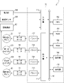
- FIG. 1 is a block diagram showing an optical fiber screening device according to a first embodiment of the present invention
- FIG. 4 is a schematic diagram showing an optical fiber screening device according to a second embodiment of the present invention
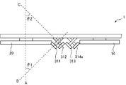
- FIG. 5 is a top view showing an optical fiber screening device according to a second embodiment of the present invention
- FIG. 3 is a schematic diagram showing an optical fiber screening device according to a third embodiment of the present invention.
- FIG. 1 An optical fiber screening apparatus and an optical fiber screening method according to a first embodiment of the present invention will be described with reference to FIGS. 1 and 2.
- FIG. 1 An optical fiber screening apparatus and an optical fiber screening method according to a first embodiment of the present invention will be described with reference to FIGS. 1 and 2.
- FIG. 1 An optical fiber screening apparatus and an optical fiber screening method according to a first embodiment of the present invention will be described with reference to FIGS. 1 and 2.
- FIG. 1 is a schematic diagram showing a screening device 1 for an optical fiber 10 according to this embodiment.
- FIG. 2 is a block diagram showing the screening device 1 for the optical fiber 10 according to this embodiment.
- the screening device 1 for the optical fiber 10 is a device for performing a screening test for testing the tensile strength performance of the optical fiber 10 .
- the screening device 1 has a payout bobbin 20 , a tension applying section 30 and a take-up bobbin 40 .
- the tension applying unit 30 includes, from the upstream side to the downstream side of the screening device 1, a pulley 301, a feed dancer 302, a first capstan 303, a pulley 304, a pulley 305, a screening dancer 307, and a second capstan.
- a stun 309 and a pulley 310 are provided in that order.
- the optical fiber 10 to be subjected to the screening test is wound around the feeding bobbin 20 .
- the delivery bobbin 20 is rotationally driven in the direction in which the optical fiber 10 is delivered by a servomotor 52 (see FIG. 2).
- the feeding bobbin 20 functions as a feeding section that feeds the optical fiber 10 toward the tension applying section 30 .
- a pulley 301 and a pulley 302a are provided in this order from the upstream side to the downstream side of the screening device 1 between the feeding bobbin 20 and the first capstan 303 .
- Pulley 302 a is the pulley of payout dancer 302 .
- the diameters of the pulleys 301 and 302a are smaller than the diameters of other pulleys to be described later. In this embodiment, the diameters of the pulleys 301 and 302a are set to 20 mm.
- a pulley having a diameter smaller than the normal size diameter is also referred to herein as a "small diameter pulley" or "first pulley”.
- a pulley having a normal size diameter is also referred to as a "normal pulley” or a "second pulley”.
- the pulleys 301 and 302a are driven and rotated by the force received from the optical fiber 10 when the optical fiber 10 is conveyed.
- the feed bobbin 20, the pulley 301, the pulley 302a and the first capstan roller 303a each have a horizontal axis of rotation. Further, the respective rotating shafts of the feeding bobbin 20, the pulley 301, the pulley 302a, and the first capstan roller 303a are parallel to each other.
- the pulley 301 is arranged above the feeding bobbin 20 .
- Pulley 302 a is arranged below pulley 301 .
- the first capstan 303 is arranged above the pulleys 301 and 302a. Furthermore, the first capstan 303 is positioned at approximately the same height as the second capstan 309 .
- the feeding bobbin 20, the pulleys 301, 302a and the first capstan 303 are arranged in a zigzag pattern in the vertical direction from the upstream side of the screening device 1 toward the downstream side.
- the optical fiber 10 fed from the feeding bobbin 20 is sequentially wound around the pulley 301, the pulley 302a and the first capstan 303 in a zigzag pattern.
- the delivery dancer 302 has a pulley 302a and a rod-like support 302b to which the pulley 302a is rotatably attached to the tip.
- the base of the support 302b has a rotation axis parallel to the rotation axis of the pulley 302a, and the support 302b is rotatable around the rotation axis.
- the pulley 302a moves up and down as the support 302b rotates. In this way, the tension applied to the optical fiber 10 is adjusted by moving the pulley 302a of the payout dancer 302 up and down on the payout side of the optical fiber 10 .
- a strike prevention plate (not shown) is preferably provided between the delivery bobbin 20 and the pulley 301 to prevent the fiber from being struck on the delivery bobbin 20 side.
- the first capstan 303 is rotationally driven by a servomotor 54 (see FIG. 2) so as to feed the optical fiber 10 fed from the feeding bobbin 20 from the upstream side of the screening apparatus 1 to the downstream side. be.
- the first capstan 303 has a first capstan roller 303a and a rotatable first endless belt 303b.
- a first endless belt 303b is pressed against the first capstan roller 303a.
- the first endless belt 303b rotates in a direction opposite to the rotation direction of the first capstan roller 303a as the first capstan roller 303a rotates.
- the optical fiber 10 is sandwiched between the first capstan roller 303a and the first endless belt 303b and sent out by the rotation of the first capstan roller 303a.
- a pulley 304, a pulley 305, and a pulley 307a are arranged on the downstream side of the first capstan 303.
- Pulley 307 a is the pulley of screening dancer 307 .
- the pulleys 304, 305 and 307a are provided in this order from the upstream side of the screening device 1 toward the downstream side.
- Pulley 304, pulley 305 and pulley 307a each have a horizontal axis of rotation.
- the rotation axes of pulley 304, pulley 305, and pulley 307a are parallel to each other, and parallel to the rotation axis of first capstan roller 303a.
- the first capstan 303 is provided with a revolution counter 62 (see FIG. 2) for measuring the number of revolutions (rotational speed) of the first capstan roller 303a.
- the tachometer 62 measures the number of rotations of the first capstan roller 303a during the screening test and outputs a measurement signal corresponding to the measured number of rotations.
- the diameters of the pulleys 304, 305 and 307a are normal sizes. In this embodiment, the diameters of the pulleys 304, 305 and 307a are set to 100 mm.
- the pulley 304 is arranged below the first capstan 303 .
- the pulley 305 is arranged above the pulley 304 and the pulley 307a.
- Pulley 305 is positioned at approximately the same height as first capstan 303 and second capstan 309, which are positioned at approximately the same height as each other.
- the pulleys 304, 305, and 307a are arranged in a zigzag pattern in the vertical direction from the upstream side of the screening apparatus 1 to the downstream side.
- the optical fiber 10 sent from the first capstan 303 is sequentially wound in a zigzag around the pulley 304, the pulley 305 and the pulley 307a.
- the screening dancer 307 has a pulley 307a and a rod-like support 307b to which the pulley 307a is rotatably attached to the tip.
- the base of the support 307b has a rotation axis parallel to the rotation axis of the pulley 307a, and the support 307b is rotatable about the rotation axis.
- the pulley 307a moves up and down as the support 307b rotates.
- the screening dancer 307 applies a constant tension to the optical fiber 10 by the weight of the vertically moving pulley 307a.
- the pulley 305 is provided with a tension meter 306 that measures the tension of the optical fiber 10 wound around the pulley 305 .
- a load cell for example, is used as the tension meter 306 .
- the tension meter 306 measures the tension of the optical fiber 10 during the screening test and outputs a measurement signal corresponding to the measured tension.
- the vertical movement of the pulley 307a by the screening dancer 307 is controlled so that the tension measured by the tension meter 306 is constant.
- a disconnection sensor 308 that detects the occurrence of disconnection of the optical fiber 10 is provided on the transport path of the optical fiber 10 in the screening device 1 .
- the disconnection sensor 308 is optical, for example, and has a light source section 308 a and a light receiving section 308 b arranged on both sides of the optical fiber 10 .
- the disconnection sensor 308 detects the occurrence of disconnection of the optical fiber 10 based on the change in the amount of light received by the light receiving unit 308b that receives the light emitted from the light source unit 308a.
- the disconnection sensor 308 outputs a detection signal when detecting the occurrence of disconnection of the optical fiber 10 .
- a disconnection sensor 308 is provided between the first capstan 303 and the pulley 304 and in the vicinity of the first capstan 303 .
- a disconnection sensor 308 is also provided near the second capstan 309 between the pulley 307 a of the screening dancer 307 and the second capstan 309 .
- disconnection sensor 308 is not limited to an optical disconnection sensor.
- disconnection sensor 308 various types of disconnection sensors such as an optical disconnection sensor and a contact-type disconnection sensor can be used.
- FIG. 1 shows a case where two disconnection sensors 308 are provided on the transport path of the optical fiber 10, the number and arrangement of the disconnection sensors 308 are not limited to this. At least one disconnection sensor 308 may be provided. Further, the place where the disconnection sensor 308 is provided in the device can be changed as appropriate.
- a second capstan 309 is provided downstream of the screening dancer 307 .
- a second capstan 309 is positioned above the screening dancers 307 .
- the optical fiber 10 fed from the screening dancer 307 is wound around the second capstan roller 309a and passed.
- the second capstan 309 has a second capstan roller 309a and a rotatable second endless belt 309b.
- the second capstan roller 309a is rotationally driven by a servomotor 58 (see FIG. 2) so as to feed the optical fiber 10 from the upstream side of the screening apparatus 1 to the downstream side.
- the second capstan roller 309a has a horizontal axis of rotation. The rotation axis of the second capstan roller 309a is parallel to the rotation axis of the first capstan roller 303a.
- a second endless belt 309b is pressed against the second capstan roller 309a.
- the second endless belt 309b rotates in a direction opposite to the rotation direction of the second capstan roller 309a as the second capstan roller 309a rotates.
- the optical fiber 10 is sandwiched between the second capstan roller 309a and the second endless belt 309b and sent out by the rotation of the second capstan roller 309a.
- a pulley 310 is provided between the second capstan 309 and the winding bobbin 40 .
- Pulley 310 has a horizontal axis of rotation. This rotation axis is parallel to the rotation axis of the second capstan roller 309a.
- the diameter of the pulley 310 is set to 100 mm, which is the normal size, like the diameters of the pulleys 304, 305 and 307a.
- One end of the optical fiber 10 wound around the pulley 310 is fixed to the take-up bobbin 40 so that it can be taken up by the take-up bobbin 40 .
- a strike prevention plate (not shown) may be provided between the pulley 310 and the take-up bobbin 40 to prevent the fiber from being struck on the take-up bobbin 40 side.
- the take-up bobbin 40 winds the optical fiber 10 that has undergone a screening test with tension applied by the tension applying unit 30 .
- the take-up bobbin 40 is rotationally driven in the direction in which the optical fiber 10 is taken up by a servomotor 60 (see FIG. 2).
- the take-up bobbin 40 functions as a take-up unit that takes up the optical fiber 10 to which tension has been applied by the tension application unit 30, that is, to which the screening test has been completed.
- the screening apparatus 1 includes a servomotor 52 that rotationally drives the feeding bobbin 20 and a servomotor 54 that rotationally drives the first capstan 303 (first capstan roller 303a). and
- the screening device 1 according to the present embodiment also has a servomotor 58 that rotationally drives the second capstan 309 (second capstan roller 309a) and a servomotor 60 that rotationally drives the winding bobbin 40. ing.
- the screening device 1 also has a control unit 70 that controls the overall operation of the screening device 1 .
- the control section 70 has a CPU (Central Processing Unit) 702 , a ROM (Read Only Memory) 704 , a RAM (Random Access Memory) 706 , a storage section 708 and an operation section 710 .
- the screening device 1 according to this embodiment also has an input section 712 and an output section 714 .
- the CPU 702 , ROM 704 , RAM 706 , storage section 708 , operation section 710 , input section 712 and output section 714 are connected to a common bus 716 .
- the controller 70 further includes a driver 722 for driving the servomotor 52, a driver 724 for driving the servomotor 54, a driver 728 for driving the servomotor 58, and a driver 728 for driving the servomotor 60. and a driver 730 of Drivers 722 , 724 , 728 , 730 are each connected to output 714 .
- the output unit 714 performs signal processing such as D/A conversion on the control signal output from the CPU 702, and outputs the control signal to the drivers 722, 724, 728, and 730 in a processable manner.
- a tension meter 306 is connected to the input unit 712 .
- the disconnection sensor 308 is connected to the input unit 712 .
- the input unit 712 is connected to the revolution counter 62 .
- the input unit 712 performs signal processing such as A/D conversion on signals input to the control unit 70 from the tension meter 306, the disconnection sensor 308, and the rotation speed counter 62, and processes the signals in the control unit 70. It enables
- the CPU 702 executes a control program and controls the overall operation of the screening device 1.
- the ROM 704 stores control programs executed by the CPU 702 .
- a RAM 706 is used as a working area when the CPU 702 executes the control program.
- the storage unit 708 stores various data referred to when the CPU 702 executes the control program. Also, the operator can make various settings related to the screening test and input instructions for executing the screening test via the operation unit 710 .
- the CPU 702 performs control to rotationally drive the feeding bobbin 20, the first capstan 303, the second capstan 309, and the winding bobbin 40 when performing the screening test.
- the CPU 702 outputs a rotation instruction signal, which is a control signal for instructing rotation of the servomotor 52 , to the driver 722 via the output unit 714 .
- the driver 722 outputs a driving signal for rotationally driving the servo motor 52 to the servo motor 52 based on the rotation instruction signal input from the CPU 702 .
- a drive signal is input from the driver 722 to the servomotor 52 to rotate the servomotor 52 .
- the feeding bobbin 20 is rotated, and the optical fiber 10 is fed from the feeding bobbin 20 on which the optical fiber 10 is wound.
- the CPU 702 also outputs a rotation instruction signal, which is a control signal for instructing rotation of the servomotor 54 , to the driver 724 via the output unit 714 .
- the driver 724 outputs a driving signal for rotationally driving the servo motor 54 to the servo motor 54 based on the rotation instruction signal input from the CPU 702 .
- a drive signal is input from the driver 724 to the servomotor 54 to rotate the servomotor 54 . Rotation of the servomotor 54 rotates the first capstan 303 to feed the optical fiber 10 downstream.
- the CPU 702 also outputs a rotation instruction signal, which is a control signal for instructing rotation of the servomotor 58 , to the driver 728 via the output unit 714 .
- the driver 728 outputs a driving signal for rotationally driving the servo motor 58 to the servo motor 58 based on the rotation instruction signal input from the CPU 702 .
- a drive signal is input from the driver 728 to the servomotor 58 to rotate the servomotor 58 . Rotation of the servomotor 58 rotates the second capstan 309 to feed the optical fiber 10 downstream.
- the CPU 702 also outputs a rotation instruction signal, which is a control signal for instructing rotation of the servomotor 60 , to the driver 730 via the output unit 714 .
- the driver 730 outputs a driving signal for rotationally driving the servo motor 60 to the servo motor 60 based on the rotation instruction signal input from the CPU 702 .
- a driving signal is input from the driver 730 to the servomotor 60 to rotate the servomotor 60 .
- the rotation of the servomotor 60 causes the winding bobbin 40 to rotate, and the optical fiber 10 to which the tension is applied by the tension applying section 30 is wound on the winding bobbin 40 .
- the feeding bobbin 20, the first capstan 303, the second capstan 309 and the winding bobbin 40 are rotated.
- the optical fiber 10 unwound from the unwinding bobbin 20 is transported at a constant line speed along a path sequentially passing through the first capstan 303, pulley 304, pulley 305, pulley 307a and second capstan 309. be.
- a constant tension is applied to the optical fiber 10 by the screening dancer 307 .
- the CPU 702 controls the motion of the screening dancer 307 so that the tension measured by the tension meter 306 is constant.
- the optical fiber 10 to which a constant tension is applied by the tension applying section 30 has a low strength portion
- the optical fiber 10 is broken at the low strength portion due to the tension applied by the tension applying section 30 and broken.
- the low-strength portion of the optical fiber 10 is caused by foreign matter, flaws, defects, etc. of the optical fiber 10 .
- the occurrence of disconnection of the optical fiber 10 is detected by the disconnection sensor 308 .
- the disconnection sensor 308 outputs a detection signal when detecting the occurrence of disconnection of the optical fiber 10 .
- a detection signal output from the disconnection sensor 308 is input to the CPU 702 via the input unit 712 .
- the CPU 702 controls the feeding bobbin 20, the first capstan 303, the second capstan 309, and the winding bobbin 40 to stop each rotation. .
- the CPU 702 performs control to stop the transfer of the optical fiber 10 when the occurrence of disconnection of the optical fiber 10 is detected.
- the CPU 702 outputs a stop instruction signal, which is a control signal for instructing the driver 722 to stop rotating the servomotor 52 , via the output unit 714 .
- the driver 722 outputs a stop signal to the servomotor 52 to stop the rotational driving of the servomotor 52 based on the stop instruction signal input from the CPU 702 .
- a stop signal is input from the driver 722 to the servomotor 52 , the rotation of the servomotor 52 is instructed to stop.
- the tension applying section 30 includes the pulleys 301 and 302a having diameters smaller than those of the normal pulleys. Therefore, the optical fiber 10 is wound around the pulleys 301 and 302a more than when the optical fiber 10 is wound around the other four normal pulleys (pulley 304, pulley 305, pulley 307a, and pulley 310). The bending angle is larger when hung. As a result, it is possible to reliably break the optical fiber 10 at a portion where strength deterioration has occurred in the optical fiber 10 . As a result, it is possible to reduce the occurrence of breakage of the optical fiber 10 in subsequent steps.
- a coating layer made of resin is normally formed on the outer peripheral portion of the optical fiber 10 . If foreign matter is mixed in the coating layer, strength deterioration occurs at the location where the foreign matter is present. However, in the conventional device that applies tension using a plurality of pulleys having the same diameter, even if the tension is applied while bending the optical fiber 10 in which a foreign substance exists in the coating layer, the inner glass part was not scratched and could not be broken.
- the screening device 1 according to the present embodiment, a pulley with a smaller diameter than usual is used, so the bending angle can be increased. This makes it possible to reliably break the optical fiber 10 at the position of the foreign matter even if the optical fiber 10 has a foreign matter in the coating layer. That is, it becomes possible to improve the accuracy of screening for the optical fiber 10 .
- the pulley 301 which is a small-diameter pulley (first pulley)
- the pulley 304 which is a normal pulley (second pulley)
- other rotating members first pulley 303 and the second capstan 309
- FIG. 3 is a schematic diagram showing the screening device 1 for the optical fiber 10 according to this embodiment.
- FIG. 4 is a top view showing the screening device 1 for the optical fiber 10 according to this embodiment.
- Components similar to those of the screening device 1 for the optical fiber 10 and the method for screening the optical fiber 10 according to the first embodiment described above are denoted by the same reference numerals, and the description thereof is omitted or simplified.
- the basic configuration of the screening device 1 for the optical fibers 10 according to this embodiment is substantially the same as the configuration of the screening device 1 for the optical fibers 10 according to the first embodiment.
- the optical fiber 10 screening device 1 according to the present embodiment is characterized in that the rotational axis of the small-diameter pulley provided between the feeding bobbin 20 and the first capstan 303 is inclined with respect to the rotational axis of the feeding bobbin 20. This is different from the optical fiber screening apparatus 1 according to the first embodiment.
- Pulley 314 a is the pulley of payout dancer 314 .
- the delivery dancer 314 also has a rod-like support 314b to which a pulley 314a is rotatably attached to the tip.
- the base of the support 314b has a rotation axis parallel to the rotation axis of the pulley 314a, and the support 314b is rotatable around the rotation axis.
- the pulley 314a moves up and down as the support 302b rotates.
- the diameter of the small-diameter pulley is 30 mm
- the diameter of the other normal pulleys is 100 mm.
- the pulleys 311, 312, 313, and 314a are arranged so that their inclination directions are alternately changed with respect to the side surface of the feeding bobbin 20.
- the rotation axis of pulley 311 is parallel to the rotation axis of pulley 313 .
- the rotation axis of pulley 312 is parallel to the rotation axis of pulley 314a.
- the rotation axis B of the pulley 311 is inclined at a predetermined inclination angle ⁇ 1 with respect to the rotation axis A of the feeding bobbin 20 .
- the rotation axis C of the pulley 312 is inclined at a predetermined inclination angle ⁇ 2 with respect to the rotation axis A of the feeding bobbin 20 .
- ⁇ 1 and ⁇ 2 are set to 45° in this embodiment, the present invention is not limited to this. That is, the inclination angle can be changed arbitrarily.
- the optical fiber 10 delivered from the delivery bobbin 20 is wound around the pulleys 311 , 312 , 313 and 314 a in this order, and then delivered to the first capstan 303 .
- the optical fiber 10 abuts the pulleys on different surfaces for each pulley. That is, regardless of the position of the foreign object in the radial direction of the optical fiber 10, the surface affected by the bending increases, so that the optical fiber 10 with deteriorated strength can be easily broken.
- FIG. 5 is a schematic diagram showing the screening device 1 for the optical fiber 10 according to this embodiment. Components similar to those of the screening device 1 for the optical fiber 10 and the method for screening the optical fiber 10 according to the first embodiment described above are denoted by the same reference numerals, and the description thereof is omitted or simplified.
- the diameter of some pulleys among the plurality of pulleys provided in the tension applying section 30 is made smaller than the diameter of the other normal pulleys has been described.
- the diameters of the plurality of pulleys are the same, and the diameter of the first capstan roller 303a (first capstan 303) is the same as that of the second capstan roller arranged on the downstream side.
- 309a (the second capstan 309) is different from the first and second embodiments.
- the diameter of the first capstan roller 303a is set to 15 mm. Also, the diameter of the second capstan roller 309a was set to 100 mm. Also, the diameter of the first capstan roller 303 a is smaller than the diameters of the plurality of pulleys 315 , 304 , 305 , 307 a and 310 . The diameter of the second capstan roller 309a may be larger or smaller than that of the plurality of normal pulleys. There may be more types of diameters of the rotating member around which the optical fiber 10 is wound.
- the first capstan 303 has a first capstan roller 303a and a rotatable first endless belt 303b.
- a first endless belt 303b is pressed against the first capstan roller 303a.
- the first endless belt 303b rotates in a direction opposite to the rotation direction of the first capstan roller 303a as the first capstan roller 303a rotates.
- the optical fiber 10 is sandwiched between the first capstan roller 303a and the first endless belt 303b and sent out by the rotation of the first capstan roller 303a.
- the second capstan 309 has a second capstan roller 309a and a rotatable second endless belt 309b.
- the optical fiber 10 is sandwiched between the second capstan roller 309a and the first endless belt 303b and sent out by the rotation of the second capstan roller 309a.
- the diameter of the first capstan roller 303a is smaller than the diameter of the second capstan roller 309a. Therefore, the first capstan 303 and the second capstan 309 greatly differ in bending angle and contact area when the optical fiber 10 is sandwiched.
- the diameter of the first capstan roller 303a is smaller than the diameter of the second capstan roller 309a, so that tension is applied while bending the optical fiber 10 at different angles. becomes possible. This makes it easier to break the optical fiber 10 whose strength is degraded.
- the control unit 70 of the screening device 1 can be realized based on a control program, which is a computer program executed by a processor such as a CPU of a programmable logic controller or other computer device.
- a control program can be created as a program that causes a processor of a computer device to execute steps for realizing each operation and each process described in the above embodiments.
- a part or all of the control program can be provided by a computer-readable recording medium recording this. Examples of such recording media include DVD-ROM (Digital Versatile Disc-Read Only Memory), CD-ROM (Compact Disc-Read Only Memory), USB (Universal Serial Bus) memory and other flash memories. can.
- part or all of the control program can be provided via a network.
- the screening apparatus 1 has a predetermined number of pulleys and dancers shown in FIG. 1, but the numbers of pulleys and dancers are limited to those shown in FIG. is not. The number of pulleys and dancers can be changed accordingly.
- the present invention is not limited to this.
- (A) the diameter of the small diameter pulley is smaller than the diameter of the normal pulley, or (B) the diameter of one capstan is smaller than the diameter of the other capstan.
- the diameter of each rotating member can be changed arbitrarily.
- the diameter of the small-diameter pulley first pulley
- the diameter of the normal pulley second pulley
- the diameter of the small-diameter pulley may be less than 100 mm.
- the diameter of one capstan is smaller than the diameter of another capstan, the diameter of the smaller capstan may be less than 100 mm.
- the diameter of the small-diameter pulley is 30% or less of that of the normal pulley, but the size ratio between the pulleys may be changed.
- the diameter of the small-diameter pulley is less than half the diameter of the normal pulley.
- the diameter of one capstan may be set to less than half the diameter of the other capstan.
- the diameter of the small-diameter pulley when the diameter of the small-diameter pulley (first pulley) is smaller than the diameter of the normal pulley (second pulley), the diameter of the small-diameter pulley may be set to 15 mm or more and less than 30 mm. Similarly, when the diameter of one capstan is smaller than the diameter of the other capstans, the diameter of the smaller capstan may be set to 15 mm or more and less than 30 mm.
- the servo motors 52, 54, 58, and 60 are used as the motors for rotationally driving the feed bobbin 20, the first capstan 303, the second capstan 309, and the take-up bobbin 40. explained in the example.
- the motors for rotating the feeding bobbin 20, the first capstan 303, the second capstan 309, and the winding bobbin 40 are not limited to servo motors, and various motors can be used. .
- the present invention is used to test the tensile strength performance of linear bodies such as wires, cables, electric wires, etc. in addition to optical fibers. It can be widely applied to screening tests.
Landscapes
- Physics & Mathematics (AREA)
- Chemical & Material Sciences (AREA)
- Analytical Chemistry (AREA)
- General Physics & Mathematics (AREA)
- Health & Medical Sciences (AREA)
- Life Sciences & Earth Sciences (AREA)
- Biochemistry (AREA)
- General Health & Medical Sciences (AREA)
- Immunology (AREA)
- Pathology (AREA)
- Investigating Strength Of Materials By Application Of Mechanical Stress (AREA)
Abstract
光ファイバに対するスクリーニングの精度を向上させる。本発明に係る光ファイバのスクリーニング装置は、光ファイバを繰り出す繰出部と、前記繰出部から繰り出された前記光ファイバに張力を印加する張力印加部と、前記張力印加部により前記張力が印加された前記光ファイバを巻き取る巻取部と、を備え、前記張力印加部は、第1のプーリ、第2のプーリ、第1のキャプスタン及び第2のキャプスタンを含み、前記第1のプーリの径は前記第2のプーリの径よりも小さく、又は、前記第1のキャプスタンの径は前記第2のキャプスタンの径よりも小さい、ことを特徴とする。
Description
本発明は、光ファイバのスクリーニング装置及び光ファイバのスクリーニング方法に関する。
光ファイバは、異物の混入、泡、傷等に起因して強度が劣化した部分があると、その劣化部分で断線してしまうことがある。そこで、線引き後の光ファイバに対しては、所定の張力を加えてその耐張力性能を試験するスクリーニング試験が行われている。スクリーニング試験は、光ファイバの製造ラインに直結されたスクリーニング装置により、製造ラインで線引きされた光ファイバに対してそのまま連続的に行われたり、線引き後にボビンに巻き取られた光ファイバに対して行われたりしている。このようなスクリーニング試験を光ファイバが経ることにより、光ファイバの断線寿命が保証されている。例えば、特許文献1には、プーリを斜めに設置することで光ファイバの多側面に対し歪みを与えるスクリーニング装置が開示されている。
また、光ファイバにおいて強度劣化が発生する要因は異物の混入、泡、傷等だけではない。通常、光ファイバのガラス部分には、紫外線硬化性を有する樹脂で被覆層が形成されている。この被覆層を形成する被覆樹脂内に異物が混入した状態で硬化されると、光ファイバをボビンなどに巻き取る際に異物により光ファイバのガラス部分に傷が入り強度劣化する場合がある。
従来のスクリーニング装置のように、光ファイバに引張強度を付加する方式では光ファイバは長手方向にのみ引張応力を受ける。しかし、光ファイバの被覆樹脂内に異物が存在する場合には、引張応力を受けても樹脂内のガラス部分には傷が付きにくいため、異物が存在する箇所で光ファイバを確実に破断させることは困難であった。
本発明は、上記に鑑みてなされたものであり、光ファイバに対するスクリーニングの精度を向上できる光ファイバのスクリーニング装置及び光ファイバのスクリーニング方法を提供することを目的とする。
本発明の一観点によれば、光ファイバを繰り出す繰出部と、前記繰出部から繰り出された前記光ファイバに張力を印加する張力印加部と、前記張力印加部により前記張力が印加された前記光ファイバを巻き取る巻取部と、を備え、前記張力印加部は、第1のプーリ、第2のプーリ、第1のキャプスタン及び第2のキャプスタンを含み、前記第1のプーリの径は前記第2のプーリの径よりも小さく、又は、前記第1のキャプスタンの径は前記第2のキャプスタンの径よりも小さい、ことを特徴とする光ファイバのスクリーニング装置が提供される。
本発明の他の観点によれば、繰出部によって光ファイバを繰り出す工程と、前記繰出部から繰り出された前記光ファイバに対して張力印加部によって張力を印加する工程と、前記張力印加部により前記張力が印加された前記光ファイバを巻取部によって巻き取る工程と、を備え、前記張力印加部は、第1のプーリ、第2のプーリ、第1のキャプスタン、第2のキャプスタンを含み、前記第1のプーリの径は前記第2のプーリの径よりも小さく、又は、前記第1のキャプスタンの径は前記第2のキャプスタンの径よりも小さい、ことを特徴とする光ファイバのスクリーニング方法が提供される。
本発明によれば、光ファイバに対するスクリーニングの精度を向上できる。
[第1実施形態]
本発明の第1実施形態による光ファイバのスクリーニング装置及び光ファイバのスクリーニング方法について図1及び図2を用いて説明する。
本発明の第1実施形態による光ファイバのスクリーニング装置及び光ファイバのスクリーニング方法について図1及び図2を用いて説明する。
まず、本実施形態による光ファイバ10のスクリーニング装置1の構成について図1及び図2を用いて説明する。図1は、本実施形態による光ファイバ10のスクリーニング装置1を示す概略図である。図2は、本実施形態による光ファイバ10のスクリーニング装置1を示すブロック図である。
本実施形態による光ファイバ10のスクリーニング装置1は、光ファイバ10の耐張力性能を試験するスクリーニング試験を行う装置である。図1に示すように、スクリーニング装置1は、繰り出しボビン20と、張力印加部30と、巻き取りボビン40とを有している。また、張力印加部30には、スクリーニング装置1の上流側から下流側に向かって、プーリ301、繰り出しダンサー302、第1のキャプスタン303、プーリ304、プーリ305、スクリーニングダンサー307、第2のキャプスタン309及びプーリ310がこの順序で設けられている。
繰り出しボビン20には、スクリーニング試験を行うべき光ファイバ10が巻かれている。繰り出しボビン20は、サーボモータ52(図2参照)により、光ファイバ10を繰り出す方向に回転駆動される。これにより、繰り出しボビン20は、光ファイバ10を張力印加部30に向けて繰り出す繰出部として機能する。
繰り出しボビン20と第1のキャプスタン303との間には、スクリーニング装置1の上流側から下流側に向かって、プーリ301と、プーリ302aとがこの順で設けられている。プーリ302aは、繰り出しダンサー302のプーリである。プーリ301及びプーリ302aの径は、後述する他のプーリの径よりも小さい。本実施形態では、プーリ301及びプーリ302aの径は、20mmとする。本明細書では、通常サイズの径よりも小さい径を有するプーリを「小径プーリ」又は「第1のプーリ」とも称する。これに対し、通常サイズの径を有するプーリを「通常プーリ」又は「第2のプーリ」とも称する。
また、プーリ301及びプーリ302aは、光ファイバ10の搬送時に、光ファイバ10から受ける力によって従動して回転する。また、繰り出しボビン20、プーリ301、プーリ302a及び第1のキャプスタンローラ303aは、それぞれ水平な回転軸を有している。また、繰り出しボビン20、プーリ301、プーリ302a、及び第1のキャプスタンローラ303aのそれぞれの回転軸は、互いに平行になっている。
プーリ301は、繰り出しボビン20よりも上方に配置されている。プーリ302aは、プーリ301よりも下方に配置されている。また、第1のキャプスタン303は、プーリ301及びプーリ302aよりも上方に配置されている。さらに、第1のキャプスタン303は、第2のキャプスタン309とほぼ同じ高さに配置されている。
このように、繰り出しボビン20、プーリ301、プーリ302a及び第1のキャプスタン303は、スクリーニング装置1の上流側から下流側に向かって、上下方向にジグザグに配置されている。繰り出しボビン20から繰り出される光ファイバ10は、プーリ301、プーリ302a及び第1のキャプスタン303に順次ジグザグに巻き掛けられて掛け渡される。
繰り出しダンサー302は、プーリ302aと、プーリ302aが先端部に回転可能に取り付けられた棒状の支持体302bとを有している。支持体302bの基部は、プーリ302aの回転軸と平行な回動軸を基部に有し、支持体302bは回動軸を中心に回動可能である。プーリ302aは、支持体302bが回動することにより上下動する。こうして、光ファイバ10の繰り出し側において、繰り出しダンサー302のプーリ302aが上下動することにより、光ファイバ10に加わる張力が調整される。なお、繰り出しボビン20とプーリ301との間には、繰り出しボビン20の側でのファイバ叩きの発生を防止するための叩き防止板(図示せず)が設けられると好適である。
第1のキャプスタン303は、繰り出しボビン20から繰り出された光ファイバ10を、サーボモータ54(図2参照)により、スクリーニング装置1の上流側から下流側に光ファイバ10を送るように回転駆動される。
第1のキャプスタン303は、第1のキャプスタンローラ303aと、回転自在な第1の無端ベルト303bとを有する。第1のキャプスタンローラ303aには、第1の無端ベルト303bが押し当てられている。第1の無端ベルト303bは、第1のキャプスタンローラ303aの回転に伴って、第1のキャプスタンローラ303aの回転方向とは逆方向に回転する。光ファイバ10は、第1のキャプスタンローラ303aと第1の無端ベルト303bとの間に挟持されつつ、第1のキャプスタンローラ303aの回転により送り出される。
第1のキャプスタン303の下流側には、プーリ304と、プーリ305と、プーリ307aとが配置されている。プーリ307aは、スクリーニングダンサー307のプーリである。プーリ304、プーリ305及びプーリ307aは、スクリーニング装置1の上流側から下流側に向かってこの順で設けられている。プーリ304、プーリ305及びプーリ307aは、それぞれ水平な回転軸を有している。また、プーリ304、プーリ305、及びプーリ307aの回転軸は、互いに平行になっており、また、第1のキャプスタンローラ303aの回転軸と平行になっている。
第1のキャプスタン303には、第1のキャプスタンローラ303aの回転数(回転速度)を計測する回転数計62(図2参照)が設けられている。回転数計62は、スクリーニング試験を行っている間の第1のキャプスタンローラ303aの回転数を計測し、計測された回転数に応じた計測信号を出力する。
また、プーリ304、プーリ305及びプーリ307aの径は、通常のサイズとする。本実施形態では、プーリ304、プーリ305及びプーリ307aの径は、100mmとする。
プーリ304は、第1のキャプスタン303よりも下方に配置されている。プーリ305は、プーリ304及びプーリ307aよりも上方に配置されている。プーリ305は、互いにほぼ同じ高さに配置された第1のキャプスタン303及び第2のキャプスタン309とほぼ同じ高さに配置されている。こうして、プーリ304、プーリ305、及びプーリ307aは、スクリーニング装置1の上流側から下流側に向かって、上下方向にジグザグに配置されている。第1のキャプスタン303から送り込まれた光ファイバ10は、プーリ304、プーリ305及びプーリ307aに順次ジグザグに巻き掛けられて掛け渡される。
スクリーニングダンサー307は、プーリ307aと、プーリ307aが先端部に回転可能に取り付けられた棒状の支持体307bとを有している。支持体307bの基部は、プーリ307aの回転軸と平行な回動軸を有し、支持体307bは回動軸を中心に回動可能になっている。プーリ307aは、支持体307bが回動することにより上下動する。こうして、スクリーニングダンサー307は、上下動するプーリ307aの重量により、光ファイバ10に一定の張力を印加する。
プーリ305には、プーリ305に巻き掛けられた光ファイバ10の張力を計測する張力計306が設けられている。張力計306としては、例えばロードセルが用いられている。張力計306は、スクリーニング試験を行っている間の光ファイバ10の張力を計測し、計測された張力に応じた計測信号を出力する。スクリーニングダンサー307によるプーリ307aの上下動は、張力計306により計測される張力が一定になるように制御される。
スクリーニング装置1における光ファイバ10の搬送経路上には、光ファイバ10の断線の発生を検出する断線センサ308が設けられている。断線センサ308は、例えば光学式のものであり、光ファイバ10の両側に配置される光源部308aと受光部308bとを有している。断線センサ308は、光源部308aから発せられた光を受光する受光部308bでの受光量の変化に基づき、光ファイバ10の断線の発生を検出する。断線センサ308は、光ファイバ10の断線の発生を検出すると、検出信号を出力する。
本実施形態では、第1のキャプスタン303とプーリ304との間であって、第1のキャプスタン303の近傍に、断線センサ308が設けられている。また、スクリーニングダンサー307のプーリ307aと第2のキャプスタン309との間であって、第2のキャプスタン309の近傍にも、断線センサ308が設けられている。
なお、断線センサ308は、光学式の断線センサに限定されるものではない。断線センサ308としては、光学式の断線センサのほか、接触式の断線センサ等の種々の方式の断線センサを用いることができる。
また、図1には、2つの断線センサ308が光ファイバ10の搬送経路上に設けられている場合を示しているが、断線センサ308の数や配置はこれに限定されるものではない。断線センサ308は、少なくとも1つ以上設けられていればよい。また、装置内において断線センサ308を設ける場所も適宜変更することができる。
スクリーニングダンサー307の下流側には、第2のキャプスタン309が設けられている。第2のキャプスタン309は、スクリーニングダンサー307よりも上方に配置されている。スクリーニングダンサー307から送り込まれた光ファイバ10は、第2のキャプスタンローラ309aに巻き掛けられて掛け渡される。
第2のキャプスタン309は、第2のキャプスタンローラ309aと、回転自在な第2の無端ベルト309bとを有している。第2のキャプスタンローラ309aは、サーボモータ58(図2参照)により、スクリーニング装置1の上流側から下流側に光ファイバ10を送るように回転駆動される。第2のキャプスタンローラ309aは、水平な回転軸を有している。また、第2のキャプスタンローラ309aの回転軸は、第1のキャプスタンローラ303aの回転軸と平行になっている。
第2のキャプスタンローラ309aには、第2の無端ベルト309bが押し当てられている。第2の無端ベルト309bは、第2のキャプスタンローラ309aの回転に伴って、第2のキャプスタンローラ309aの回転方向とは逆方向に回転する。光ファイバ10は、第2のキャプスタンローラ309aと第2の無端ベルト309bとの間に挟持されつつ、第2のキャプスタンローラ309aの回転により送り出される。
第2のキャプスタン309と巻き取りボビン40との間には、プーリ310が設けられている。プーリ310は、水平な回転軸を有している。この回転軸は、第2のキャプスタンローラ309aの回転軸と平行になっている。また、本実施形態では、プーリ310の径は、プーリ304、プーリ305及びプーリ307aの径と同じく、通常サイズである100mmとする。
プーリ310に巻き掛けられた光ファイバ10は、巻き取りボビン40により巻き取られるように一端が巻き取りボビン40に固定される。なお、プーリ310と巻き取りボビン40との間には、巻き取りボビン40の側でのファイバ叩きの発生を防止するための叩き防止板(図示せず)が設けられてもよい。
巻き取りボビン40は、張力印加部30により張力が印加されてスクリーニング試験を経た光ファイバ10を巻き取るものである。巻き取りボビン40は、サーボモータ60(図2参照)により、光ファイバ10を巻き取る方向に回転駆動される。これにより、巻き取りボビン40は、張力印加部30において張力が印加された、すなわち、スクリーニング試験が完了した光ファイバ10を巻き取る巻取部として機能する。
図2に示すように、本実施形態によるスクリーニング装置1は、繰り出しボビン20を回転駆動するサーボモータ52と、第1のキャプスタン303(第1のキャプスタンローラ303a)を回転駆動するサーボモータ54とを有している。また、本実施形態によるスクリーニング装置1は、第2のキャプスタン309(第2のキャプスタンローラ309a)を回転駆動するサーボモータ58と、巻き取りボビン40を回転駆動するサーボモータ60とを有している。
また、本実施形態によるスクリーニング装置1は、スクリーニング装置1の全体の動作を制御する制御部70を有している。制御部70は、CPU(Central Processing Unit)702と、ROM(Read Only Memory)704と、RAM(Random Access Memory)706と、記憶部708と、操作部710とを有している。また、本実施形態によるスクリーニング装置1は、入力部712と、出力部714とを有している。CPU702、ROM704、RAM706、記憶部708、操作部710、入力部712、及び出力部714は、共通バス716に接続されている。
制御部70は、さらに、サーボモータ52を駆動するためのドライバ722と、サーボモータ54を駆動するためのドライバ724と、サーボモータ58を駆動するためのドライバ728と、サーボモータ60を駆動するためのドライバ730とを有している。ドライバ722、724、728、730は、それぞれ出力部714に接続されている。出力部714は、CPU702から出力された制御信号に対してD/A変換等の信号処理を行い、その制御信号を処理可能にドライバ722、724、728、730に出力するものである。
入力部712には、張力計306が接続されている。また、入力部712には、断線センサ308が接続されている。また、入力部712には、回転数計62が接続されている。入力部712は、張力計306、断線センサ308、及び回転数計62から制御部70に入力される信号に対してA/D変換等の信号処理を行い、その信号の制御部70での処理を可能にするものである。
CPU702は、制御プログラムを実行し、スクリーニング装置1の全体の動作を制御する。ROM704には、CPU702が実行する制御プログラムが記憶されている。RAM706は、CPU702が制御プログラムを実行する際のワーキングエリアとして使用される。記憶部708は、CPU702が制御プログラムを実行する際に参照する各種データが記憶されている。また、オペレータは、操作部710を介して、スクリーニング試験に関する各種設定を行ったり、スクリーニング試験の実行の指示を入力したりすることができる。
CPU702は、スクリーニング試験を行うに際して、繰り出しボビン20、第1のキャプスタン303、第2のキャプスタン309、及び巻き取りボビン40を回転駆動する制御を行う。
具体的には、CPU702は、出力部714を介して、ドライバ722に対して、サーボモータ52の回転駆動を指示する制御信号である回転指示信号を出力する。ドライバ722は、CPU702から入力される回転指示信号に基づき、サーボモータ52に対して、サーボモータ52を回転駆動する駆動信号を出力する。ドライバ722からサーボモータ52に駆動信号が入力されることにより、サーボモータ52が回転する。サーボモータ52が回転することにより、繰り出しボビン20が回転して、光ファイバ10が巻かれた繰り出しボビン20から光ファイバ10が繰り出される。
また、CPU702は、出力部714を介して、ドライバ724に対して、サーボモータ54の回転駆動を指示する制御信号である回転指示信号を出力する。ドライバ724は、CPU702から入力される回転指示信号に基づき、サーボモータ54に対して、サーボモータ54を回転駆動する駆動信号を出力する。ドライバ724からサーボモータ54に駆動信号が入力されることにより、サーボモータ54が回転する。サーボモータ54が回転することにより、第1のキャプスタン303が回転して、光ファイバ10が下流側に送り込まれる。
また、CPU702は、出力部714を介して、ドライバ728に対して、サーボモータ58の回転駆動を指示する制御信号である回転指示信号を出力する。ドライバ728は、CPU702から入力される回転指示信号に基づき、サーボモータ58に対して、サーボモータ58を回転駆動する駆動信号を出力する。ドライバ728からサーボモータ58に駆動信号が入力されることにより、サーボモータ58が回転する。サーボモータ58が回転することにより、第2のキャプスタン309が回転して、光ファイバ10が下流側に送り出される。
また、CPU702は、出力部714を介して、ドライバ730に対して、サーボモータ60の回転駆動を指示する制御信号である回転指示信号を出力する。ドライバ730は、CPU702から入力される回転指示信号に基づき、サーボモータ60に対して、サーボモータ60を回転駆動する駆動信号を出力する。ドライバ730からサーボモータ60に駆動信号が入力されることにより、サーボモータ60が回転する。サーボモータ60が回転することにより、巻き取りボビン40が回転して、張力印加部30により張力が印加された光ファイバ10が巻き取りボビン40に巻き取られる。
こうして、スクリーニング試験では、繰り出しボビン20、第1のキャプスタン303、第2のキャプスタン309及び巻き取りボビン40が回転する。これにより、繰り出しボビン20から繰り出された光ファイバ10は、第1のキャプスタン303、プーリ304、プーリ305、プーリ307a及び第2のキャプスタン309を順次経由する経路を一定の線速で移送される。この間、光ファイバ10に対して、スクリーニングダンサー307により、一定の張力が印加される。
CPU702は、入力部712を介して張力計306から入力される計測信号に基づき、張力計306により計測される張力が一定になるようにスクリーニングダンサー307の動作を制御する。
張力印加部30において一定の張力が印加される光ファイバ10に低強度部があると、光ファイバ10は、張力印加部30により印加される張力により低強度部で破断して断線する。光ファイバ10の低強度部は、光ファイバ10の異物、傷、欠陥等に起因するものである。
光ファイバ10の断線の発生は、断線センサ308により検出される。断線センサ308は、光ファイバ10の断線の発生を検出すると、検出信号を出力する。断線センサ308から出力された検出信号は、入力部712を介してCPU702に入力される。
CPU702は、断線センサ308から検出信号が入力されると、繰り出しボビン20、第1のキャプスタン303、第2のキャプスタン309及び巻き取りボビン40の各回転を停止するようにこれらの制御を行う。こうして、CPU702は、光ファイバ10の断線の発生が検出されると、光ファイバ10の移送を停止する制御を行う。
具体的には、CPU702は、出力部714を介して、ドライバ722に対して、サーボモータ52の回転駆動の停止を指示する制御信号である停止指示信号を出力する。ドライバ722は、CPU702から入力される停止指示信号に基づき、サーボモータ52に対して、サーボモータ52の回転駆動を停止する停止信号を出力する。ドライバ722からサーボモータ52に停止信号が入力されることにより、サーボモータ52の回転駆動の停止が指示される。
このように、本実施形態によれば、張力印加部30の中に、通常プーリよりも径が小さいプーリ301及びプーリ302aが含まれている。このため、他の4つの通常プーリ(プーリ304、プーリ305、プーリ307a、プーリ310)に対して光ファイバ10が巻き掛けられた場合よりも、プーリ301及びプーリ302aに対して光ファイバ10が巻き掛けられた場合の方が曲げ角度が大きくなる。これにより、光ファイバ10内において強度劣化が生じている部分で、光ファイバ10を確実に破断させることが可能になる。その結果、後続の工程での光ファイバ10の破断発生を低減することができる。
通常、光ファイバ10の外周部には、樹脂からなる被覆層が形成されている。この被覆層の中に異物が混入していた場合には、異物が存在する箇所で強度劣化が生じる。しかし、同等の径を有する複数のプーリを用いて張力を印加する従来型の装置では、被覆層内に異物が存在する光ファイバ10に対して折り曲げながら張力を印加しても、内部のガラス部分に傷が付かず、破断できない場合があった。
これに対し、本実施形態に係るスクリーニング装置1によれば、通常よりも小径のプーリを用いるため、折り曲げ角度を大きくできる。これにより、被覆層内に異物が存在する光ファイバ10に対しても、当該異物の位置で、光ファイバ10を確実に破断させることが可能になる。すなわち、光ファイバ10に対するスクリーニングの精度を向上させることが可能となる。
また、本実施形態では、光ファイバ10の搬送方向において、小径プーリ(第1のプーリ)であるプーリ301は、通常プーリ(第2のプーリ)であるプーリ304や、他の回転部材(第1のキャプスタン303及び第2のキャプスタン309)よりも上流側に配置される。これにより、光ファイバ10の搬送方向の上流側において、下流側と異なる、より大きな曲げ角度で張力を印加できる。
[第2実施形態]
本発明の第2実施形態による光ファイバ10のスクリーニング装置1及び光ファイバ10のスクリーニング方法について図3及び図4を用いて説明する。図3は、本実施形態による光ファイバ10のスクリーニング装置1を示す概略図である。図4は、本実施形態による光ファイバ10のスクリーニング装置1を示す上面図である。なお、上述した第1実施形態による光ファイバ10のスクリーニング装置1及び光ファイバ10のスクリーニング方法と同様の構成要素については同一の符号を付し説明を省略し又は簡略にする。
本発明の第2実施形態による光ファイバ10のスクリーニング装置1及び光ファイバ10のスクリーニング方法について図3及び図4を用いて説明する。図3は、本実施形態による光ファイバ10のスクリーニング装置1を示す概略図である。図4は、本実施形態による光ファイバ10のスクリーニング装置1を示す上面図である。なお、上述した第1実施形態による光ファイバ10のスクリーニング装置1及び光ファイバ10のスクリーニング方法と同様の構成要素については同一の符号を付し説明を省略し又は簡略にする。
本実施形態による光ファイバ10のスクリーニング装置1の基本的構成は、第1実施形態による光ファイバ10のスクリーニング装置1の構成とほぼ同様である。本実施形態による光ファイバ10のスクリーニング装置1は、繰り出しボビン20と第1のキャプスタン303との間に設けられた小径プーリの回転軸が、繰り出しボビン20の回転軸に対して傾いている点で、第1実施形態による光ファイバのスクリーニング装置1とは異なっている。
図3に示されるように、繰り出しボビン20と第1のキャプスタン303との間には、小径プーリであるプーリ311、プーリ312、プーリ313及びプーリ314aが含まれている。プーリ314aは、繰り出しダンサー314のプーリである。また、繰り出しダンサー314は、プーリ314aが先端部に回転可能に取り付けられた棒状の支持体314bを有している。支持体314bの基部は、プーリ314aの回転軸と平行な回動軸を有し、支持体314bは回動軸を中心に回動可能である。プーリ314aは、支持体302bが回動することにより上下動する。なお、本実施形態では、小径プーリの径は30mmとし、他の通常プーリの径は100mmとする。
また、プーリ311、プーリ312、プーリ313及びプーリ314aは、繰り出しボビン20の側面に対して、傾斜方向を交互に変更して配置されている。これにより、繰り出しボビン20と第1のキャプスタン303との間において、光ファイバ10の搬送経路は、上面視でジグザグとなる。プーリ311の回転軸は、プーリ313の回転軸と平行である。プーリ312の回転軸は、プーリ314aの回転軸と平行である。
また、図4に示されるように、繰り出しボビン20の回転軸Aに対して、プーリ311の回転軸Bは、所定の傾斜角度θ1で傾斜する。同様に、繰り出しボビン20の回転軸Aに対して、プーリ312の回転軸Cは、所定の傾斜角度θ2で傾斜する。なお、本実施形態では、θ1及びθ2は45°とするが、これに限られない。すなわち、傾斜角度は任意に変更できる。
繰り出しボビン20から送り出された光ファイバ10は、プーリ311、プーリ312、プーリ313及びプーリ314aの順序で巻き掛けられ、その後、第1のキャプスタン303に送り出される。
このように、本実施形態によれば、繰り出しボビン20と第1のキャプスタン303との間に、繰り出しボビン20の回転軸に対して、小径プーリの回転軸が傾斜するように、4つの小径プーリが設けられている。これにより、光ファイバ10はプーリごとに異なる面でプーリに当接する。すなわち、異物が光ファイバ10の径方向のどのような位置に存在する場合でも、折り曲げの影響を受ける面が増えるため、強度劣化が生じている光ファイバ10の破断が容易になる。
[第3実施形態]
本発明の第3実施形態による光ファイバ10のスクリーニング装置1及び光ファイバ10のスクリーニング方法について図5を用いて説明する。図5は、本実施形態による光ファイバ10のスクリーニング装置1を示す概略図である。なお、上述した第1実施形態による光ファイバ10のスクリーニング装置1及び光ファイバ10のスクリーニング方法と同様の構成要素については同一の符号を付し説明を省略し又は簡略にする。
本発明の第3実施形態による光ファイバ10のスクリーニング装置1及び光ファイバ10のスクリーニング方法について図5を用いて説明する。図5は、本実施形態による光ファイバ10のスクリーニング装置1を示す概略図である。なお、上述した第1実施形態による光ファイバ10のスクリーニング装置1及び光ファイバ10のスクリーニング方法と同様の構成要素については同一の符号を付し説明を省略し又は簡略にする。
上述した第1実施形態及び第2実施形態では、張力印加部30に設けられた複数のプーリのうちの一部のプーリの径を他の通常プーリの径よりも小さくする場合について説明した。これに対し、本実施形態は、複数のプーリの径は同じ大きさとし、第1のキャプスタンローラ303a(第1のキャプスタン303)の径を、下流側に配置された第2のキャプスタンローラ309a(第2のキャプスタン309)の径よりも小さくする点において第1実施形態及び第2実施形態とは異なる。
本実施形態において、第1のキャプスタンローラ303aの径は、15mmとした。また、第2のキャプスタンローラ309aの径は、100mmとした。また、第1のキャプスタンローラ303aの径は、複数のプーリ315、304、305、307a及び310の径よりも小さい。なお、第2のキャプスタンローラ309aの径は、複数の通常プーリよりも大きくてもよいし、小さくてもよい。光ファイバ10が巻き掛けられる回転部材の径の種類は、さらに多くてもよい。
第1のキャプスタン303は、第1のキャプスタンローラ303aと、回転自在な第1の無端ベルト303bとを有する。第1のキャプスタンローラ303aには、第1の無端ベルト303bが押し当てられている。第1の無端ベルト303bは、第1のキャプスタンローラ303aの回転に伴って、第1のキャプスタンローラ303aの回転方向とは逆方向に回転する。光ファイバ10は、第1のキャプスタンローラ303aと第1の無端ベルト303bとの間に挟持されつつ、第1のキャプスタンローラ303aの回転により送り出される。
同様に、第2のキャプスタン309は、第2のキャプスタンローラ309aと、回転自在な第2の無端ベルト309bとを有する。光ファイバ10は、第2のキャプスタンローラ309aと第1の無端ベルト303bとの間に挟持されつつ、第2のキャプスタンローラ309aの回転により送り出される。
しかし、第1のキャプスタンローラ303aの径は、第2のキャプスタンローラ309aの径よりも小さい。このため、第1のキャプスタン303と第2のキャプスタン309とでは、光ファイバ10を挟み込む際の折り曲げ角度及び接触面積が大きく異なる。
このように、本実施形態によれば、第1のキャプスタンローラ303aの径は、第2のキャプスタンローラ309aの径よりも小さいため、異なる角度で光ファイバ10を折り曲げながら、張力を印加させることが可能となる。これにより、強度劣化が生じている光ファイバ10の破断がさらに容易になる。
[他の実施形態]
上述した実施形態によるスクリーニング装置1の制御部70は、プログラマブルロジックコントローラその他のコンピュータ装置のCPU等のプロセッサにより実行されるコンピュータプログラムである制御プログラムに基づき実現することができる。このような制御プログラムは、上述した実施形態において説明した各動作及び各処理を実現するステップをコンピュータ装置のプロセッサに実行させるプログラムとして作成することができる。制御プログラムの一部又は全部は、これを記録したコンピュータ読み取り可能な記録媒体により提供することができる。このような記録媒体としては、DVD-ROM(Digital Versatile Disc-Read Only Memory)、CD-ROM(Compact Disc-Read Only Memory)、USB(Universal Serial Bus)メモリその他のフラッシュメモリ等を例示することができる。また、制御プログラムの一部又は全部は、ネットワークを介して提供することもできる。
上述した実施形態によるスクリーニング装置1の制御部70は、プログラマブルロジックコントローラその他のコンピュータ装置のCPU等のプロセッサにより実行されるコンピュータプログラムである制御プログラムに基づき実現することができる。このような制御プログラムは、上述した実施形態において説明した各動作及び各処理を実現するステップをコンピュータ装置のプロセッサに実行させるプログラムとして作成することができる。制御プログラムの一部又は全部は、これを記録したコンピュータ読み取り可能な記録媒体により提供することができる。このような記録媒体としては、DVD-ROM(Digital Versatile Disc-Read Only Memory)、CD-ROM(Compact Disc-Read Only Memory)、USB(Universal Serial Bus)メモリその他のフラッシュメモリ等を例示することができる。また、制御プログラムの一部又は全部は、ネットワークを介して提供することもできる。
[変形実施形態]
本発明は、上述した実施形態に限らず、種々の変形が可能である。
本発明は、上述した実施形態に限らず、種々の変形が可能である。
例えば、上述した実施形態では、スクリーニング装置1について図1に示す所定の数のプーリ及びダンサーを有する装置構成を例に説明したが、プーリ及びダンサーの数は図1に示す場合に限定されるものではない。プーリ及びダンサーの数は、適宜変更することができる。
また、上述した実施形態では、小径プーリ、小径のキャプスタンローラ及び通常プーリの径の値の一例を示したが、これに限られない。張力印加部30において、(A)小径プーリの径は通常プーリの径よりも小さいこと、又は、(B)一方のキャプスタンの径は他方のキャプスタンの径よりも小さいこと、を満たしていればよい。各回転部材の径は、任意に変更可能である。小径プーリ(第1のプーリ)の径が通常プーリ(第2のプーリ)の径よりも小さい場合、小径プーリの径が100mm未満としてもよい。さらに、一のキャプスタンの径が他のキャプスタンの径よりも小さい場合、小径のキャプスタンの径は100mm未満としてもよい。
例えば、上述した実施形態では、小径プーリの径は通常プーリの30%以下であったが、プーリ間の大きさの比率を変更してもよい。例えば、小径プーリの径は通常プーリの径の半分以下であると好適である。同様に、一のキャプスタンの径は他のキャプスタンの径の半分以下に設定してもよい。
また、小径プーリ(第1のプーリ)の径が通常プーリ(第2のプーリ)の径よりも小さい場合、小径プーリの径は15mm以上、かつ、30mm未満に設定してもよい。同様に、一のキャプスタンの径が他のキャプスタンの径よりも小さい場合、小径のキャプスタンの径は、15mm以上、かつ、30mm未満に設定してもよい。
また、上述した実施形態では、繰り出しボビン20、第1のキャプスタン303、第2のキャプスタン309、及び巻き取りボビン40を回転駆動するモータとしてサーボモータ52、54、58、60を用いる場合を例に説明した。しかしながら、繰り出しボビン20、第1のキャプスタン303、第2のキャプスタン309、及び巻き取りボビン40を回転駆動するモータは、サーボモータに限定されるものではなく、種々のモータを用いることができる。
また、上述した実施形態では、光ファイバ10についてスクリーニング試験を行う場合を例に説明したが、本発明は、光ファイバのほか、ワイヤ、ケーブル、電線等の線状体の耐張力性能を試験するスクリーニング試験に広く適用することができる。
1…スクリーニング装置
10…光ファイバ
20…繰り出しボビン
30…張力印加部
40…巻き取りボビン
301…プーリ
302…繰り出しダンサー
302a…プーリ
302b…支持体
303…第1のキャプスタン
303a…第1のキャプスタンローラ
303b…第1の無端ベルト
304…プーリ
305…プーリ
306…張力計
307…スクリーニングダンサー
307a…プーリ
307b…支持体
308…断線センサ
308a…光源部
308b…受光部
309…第2のキャプスタン
309a…第2のキャプスタンローラ
309b…第2の無端ベルト
310、311、312、313、315…プーリ
314…繰り出しダンサー
314a…プーリ
314b…支持体
Claims (9)
- 光ファイバを繰り出す繰出部と、
前記繰出部から繰り出された前記光ファイバに張力を印加する張力印加部と、
前記張力印加部により前記張力が印加された前記光ファイバを巻き取る巻取部と、
を備え、
前記張力印加部は、第1のプーリ、第2のプーリ、第1のキャプスタン及び第2のキャプスタンを含み、
前記第1のプーリの径は前記第2のプーリの径よりも小さく、又は、前記第1のキャプスタンの径は前記第2のキャプスタンの径よりも小さい、
ことを特徴とする光ファイバのスクリーニング装置。 - 前記第1のプーリの径が前記第2のプーリの径よりも小さい場合、
前記光ファイバの搬送方向において、前記第1のプーリは、前記第2のプーリ、前記第1のキャプスタン及び前記第2のキャプスタンよりも上流側に配置される、
ことを特徴とする請求項1に記載の光ファイバのスクリーニング装置。 - 前記第1のプーリの回転軸は、前記繰出部の回転軸に対して傾いている、
ことを特徴とする請求項2に記載の光ファイバのスクリーニング装置。 - 前記第1のプーリは、100mm未満である、
ことを特徴とする請求項2又は3に記載の光ファイバのスクリーニング装置。 - 前記第1のプーリの径は、15mm以上、かつ、30mm未満である、
ことを特徴とする請求項4に記載の光ファイバのスクリーニング装置。 - 前記第1のキャプスタンの径が前記第2のキャプスタンの径よりも小さい場合、
前記第1のキャプスタンの径は、100mm未満である、
ことを特徴とする請求項1乃至5のいずれか1項に記載の光ファイバのスクリーニング装置。 - 前記第1のキャプスタンの径は、15mm以上、かつ、30mm未満である、
ことを特徴とする請求項6に記載の光ファイバのスクリーニング装置。 - 前記第1のプーリは、複数設けられる、
ことを特徴とする請求項1乃至7のいずれか1項に記載の光ファイバのスクリーニング装置。 - 繰出部によって光ファイバを繰り出す工程と、
前記繰出部から繰り出された前記光ファイバに対して張力印加部によって張力を印加する工程と、
前記張力印加部により前記張力が印加された前記光ファイバを巻取部によって巻き取る工程と、
を備え、
前記張力印加部は、第1のプーリ、第2のプーリ、第1のキャプスタン、第2のキャプスタンを含み、
前記第1のプーリの径は前記第2のプーリの径よりも小さく、又は、前記第1のキャプスタンの径は前記第2のキャプスタンの径よりも小さい、
ことを特徴とする光ファイバのスクリーニング方法。
Priority Applications (1)
| Application Number | Priority Date | Filing Date | Title |
|---|---|---|---|
| US18/518,791 US12699030B2 (en) | 2021-05-27 | 2023-11-24 | Screening apparatus for optical fiber and screening method for optical fiber |
Applications Claiming Priority (2)
| Application Number | Priority Date | Filing Date | Title |
|---|---|---|---|
| JP2021-089567 | 2021-05-27 | ||
| JP2021089567A JP7382985B2 (ja) | 2021-05-27 | 2021-05-27 | 光ファイバのスクリーニング装置及び光ファイバのスクリーニング方法 |
Related Child Applications (1)
| Application Number | Title | Priority Date | Filing Date |
|---|---|---|---|
| US18/518,791 Continuation US12699030B2 (en) | 2021-05-27 | 2023-11-24 | Screening apparatus for optical fiber and screening method for optical fiber |
Publications (1)
| Publication Number | Publication Date |
|---|---|
| WO2022250029A1 true WO2022250029A1 (ja) | 2022-12-01 |
Family
ID=84228871
Family Applications (1)
| Application Number | Title | Priority Date | Filing Date |
|---|---|---|---|
| PCT/JP2022/021176 Ceased WO2022250029A1 (ja) | 2021-05-27 | 2022-05-24 | 光ファイバのスクリーニング装置及び光ファイバのスクリーニング方法 |
Country Status (3)
| Country | Link |
|---|---|
| US (1) | US12699030B2 (ja) |
| JP (1) | JP7382985B2 (ja) |
| WO (1) | WO2022250029A1 (ja) |
Citations (8)
| Publication number | Priority date | Publication date | Assignee | Title |
|---|---|---|---|---|
| JPS60179625A (ja) * | 1984-02-27 | 1985-09-13 | Nippon Telegr & Teleph Corp <Ntt> | 光フアイバプル−フテスト装置 |
| JPH04164228A (ja) * | 1990-10-29 | 1992-06-09 | Furukawa Electric Co Ltd:The | 光ファイバスクリーニングにおける伸び率検出方法 |
| JPH1183672A (ja) * | 1997-09-09 | 1999-03-26 | Hitachi Cable Ltd | 光ファイバスクリーニング装置 |
| US20040155140A1 (en) * | 2003-02-11 | 2004-08-12 | Stephen Mast | Rewinder method and apparatus |
| JP2017521340A (ja) * | 2014-05-09 | 2017-08-03 | コーニング インコーポレイテッド | 光ファイバーの選別試験装置及びその使用方法 |
| WO2017159848A1 (ja) * | 2016-03-18 | 2017-09-21 | 古河電気工業株式会社 | 光ファイバのスクリーニング装置及び光ファイバのスクリーニング方法 |
| JP2018528392A (ja) * | 2015-06-08 | 2018-09-27 | コーニング インコーポレイテッド | 光ファイバーをスクリーン試験するための一体型キャプスタンおよび装置 |
| JP2018173382A (ja) * | 2017-03-31 | 2018-11-08 | 古河電気工業株式会社 | 光ファイバのスクリーニング装置 |
Family Cites Families (1)
| Publication number | Priority date | Publication date | Assignee | Title |
|---|---|---|---|---|
| US8689636B2 (en) | 2012-03-29 | 2014-04-08 | Corning Incorporated | Optical fiber tensile screening method and device |
-
2021
- 2021-05-27 JP JP2021089567A patent/JP7382985B2/ja active Active
-
2022
- 2022-05-24 WO PCT/JP2022/021176 patent/WO2022250029A1/ja not_active Ceased
-
2023
- 2023-11-24 US US18/518,791 patent/US12699030B2/en active Active
Patent Citations (8)
| Publication number | Priority date | Publication date | Assignee | Title |
|---|---|---|---|---|
| JPS60179625A (ja) * | 1984-02-27 | 1985-09-13 | Nippon Telegr & Teleph Corp <Ntt> | 光フアイバプル−フテスト装置 |
| JPH04164228A (ja) * | 1990-10-29 | 1992-06-09 | Furukawa Electric Co Ltd:The | 光ファイバスクリーニングにおける伸び率検出方法 |
| JPH1183672A (ja) * | 1997-09-09 | 1999-03-26 | Hitachi Cable Ltd | 光ファイバスクリーニング装置 |
| US20040155140A1 (en) * | 2003-02-11 | 2004-08-12 | Stephen Mast | Rewinder method and apparatus |
| JP2017521340A (ja) * | 2014-05-09 | 2017-08-03 | コーニング インコーポレイテッド | 光ファイバーの選別試験装置及びその使用方法 |
| JP2018528392A (ja) * | 2015-06-08 | 2018-09-27 | コーニング インコーポレイテッド | 光ファイバーをスクリーン試験するための一体型キャプスタンおよび装置 |
| WO2017159848A1 (ja) * | 2016-03-18 | 2017-09-21 | 古河電気工業株式会社 | 光ファイバのスクリーニング装置及び光ファイバのスクリーニング方法 |
| JP2018173382A (ja) * | 2017-03-31 | 2018-11-08 | 古河電気工業株式会社 | 光ファイバのスクリーニング装置 |
Also Published As
| Publication number | Publication date |
|---|---|
| US12699030B2 (en) | 2026-08-04 |
| JP2022182175A (ja) | 2022-12-08 |
| US20240094102A1 (en) | 2024-03-21 |
| JP7382985B2 (ja) | 2023-11-17 |
Similar Documents
| Publication | Publication Date | Title |
|---|---|---|
| US10618788B2 (en) | Hoist cable load sensor | |
| US6735933B2 (en) | Method and apparatus for axial feed of ribbon material | |
| JP6443896B2 (ja) | フレキシブルガラスリボンを検査する装置および方法 | |
| US11143574B2 (en) | Screening apparatus for optical fiber and screening method for optical fiber | |
| CN101035730A (zh) | 连续纱线的传送筒子架 | |
| CN105259049A (zh) | 钢丝绳弯曲和扭转性能测试方法及设备 | |
| CN1365944A (zh) | 纱条加工装置、方法及具有质量表示功能的卷取卷装 | |
| EP2690043B1 (en) | Driving state detecting device, winding unit, winding machine, spinning unit, and spinning machine | |
| JP2022182175A (ja) | 光ファイバのスクリーニング装置及び光ファイバのスクリーニング方法 | |
| CN104160262B (zh) | 树脂膜的劣化检测方法及树脂膜的劣化检测装置 | |
| CN101089555A (zh) | 光纤陀螺绕线机的张力控制结构 | |
| JP4979475B2 (ja) | 撚線の残留トーション測定装置並びにそれを備えた撚線機および撚線の巻取り機 | |
| JP6632563B2 (ja) | 光ファイバのスクリーニング装置 | |
| JP3211717U (ja) | 細径線材の表面検査装置 | |
| JP2008179434A (ja) | 撚糸機 | |
| JP2014024652A (ja) | 糸巻取装置 | |
| EP3303200B1 (en) | Winding of multiple elongated elements | |
| CN205529649U (zh) | 用于多线放线系统的张力缓冲系统 | |
| US6726142B2 (en) | Twist controlling device, rotatable nip and axial feed system | |
| CN112623857A (zh) | 一种多经轴纱线退绕装置 | |
| JP7495302B2 (ja) | 電線製造装置及び捩れ解消装置 | |
| JP2013184815A (ja) | ワイヤー搬送装置及びそれを用いたワイヤー処理装置 | |
| JP2011219253A (ja) | 被検査部品搬送装置及び搬送方法 | |
| JP4750852B2 (ja) | コーティングラインにおける方法およびそのライン構成 | |
| JPS60179626A (ja) | 光フアイバ応力−歪特性測定方法および装置 |
Legal Events
| Date | Code | Title | Description |
|---|---|---|---|
| 121 | Ep: the epo has been informed by wipo that ep was designated in this application |
Ref document number: 22811299 Country of ref document: EP Kind code of ref document: A1 |
|
| WWE | Wipo information: entry into national phase |
Ref document number: 202347087129 Country of ref document: IN |
|
| NENP | Non-entry into the national phase |
Ref country code: DE |
|
| 122 | Ep: pct application non-entry in european phase |
Ref document number: 22811299 Country of ref document: EP Kind code of ref document: A1 |