WO2022250002A1 - 内視鏡用処置具 - Google Patents
内視鏡用処置具 Download PDFInfo
- Publication number
- WO2022250002A1 WO2022250002A1 PCT/JP2022/021059 JP2022021059W WO2022250002A1 WO 2022250002 A1 WO2022250002 A1 WO 2022250002A1 JP 2022021059 W JP2022021059 W JP 2022021059W WO 2022250002 A1 WO2022250002 A1 WO 2022250002A1
- Authority
- WO
- WIPO (PCT)
- Prior art keywords
- treatment
- pair
- liquid
- sheath
- link
- Prior art date
- Legal status (The legal status is an assumption and is not a legal conclusion. Google has not performed a legal analysis and makes no representation as to the accuracy of the status listed.)
- Ceased
Links
Images



Classifications
-
- A—HUMAN NECESSITIES
- A61—MEDICAL OR VETERINARY SCIENCE; HYGIENE
- A61B—DIAGNOSIS; SURGERY; IDENTIFICATION
- A61B17/00—Surgical instruments, devices or methods
- A61B17/28—Surgical forceps
- A61B17/29—Forceps for use in minimally invasive surgery
-
- A—HUMAN NECESSITIES
- A61—MEDICAL OR VETERINARY SCIENCE; HYGIENE
- A61B—DIAGNOSIS; SURGERY; IDENTIFICATION
- A61B18/00—Surgical instruments, devices or methods for transferring non-mechanical forms of energy to or from the body
- A61B18/04—Surgical instruments, devices or methods for transferring non-mechanical forms of energy to or from the body by heating
- A61B18/08—Surgical instruments, devices or methods for transferring non-mechanical forms of energy to or from the body by heating by means of electrically-heated probes
- A61B18/082—Probes or electrodes therefor
- A61B18/085—Forceps, scissors
-
- A—HUMAN NECESSITIES
- A61—MEDICAL OR VETERINARY SCIENCE; HYGIENE
- A61B—DIAGNOSIS; SURGERY; IDENTIFICATION
- A61B10/00—Instruments for taking body samples for diagnostic purposes; Other methods or instruments for diagnosis, e.g. for vaccination diagnosis, sex determination or ovulation-period determination; Throat striking implements
- A61B10/02—Instruments for taking cell samples or for biopsy
- A61B10/06—Biopsy forceps, e.g. with cup-shaped jaws
-
- A—HUMAN NECESSITIES
- A61—MEDICAL OR VETERINARY SCIENCE; HYGIENE
- A61B—DIAGNOSIS; SURGERY; IDENTIFICATION
- A61B18/00—Surgical instruments, devices or methods for transferring non-mechanical forms of energy to or from the body
- A61B18/04—Surgical instruments, devices or methods for transferring non-mechanical forms of energy to or from the body by heating
- A61B18/12—Surgical instruments, devices or methods for transferring non-mechanical forms of energy to or from the body by heating by passing a current through the tissue to be heated, e.g. high-frequency current
- A61B18/14—Probes or electrodes therefor
- A61B18/1442—Probes having pivoting end effectors, e.g. forceps
-
- A—HUMAN NECESSITIES
- A61—MEDICAL OR VETERINARY SCIENCE; HYGIENE
- A61B—DIAGNOSIS; SURGERY; IDENTIFICATION
- A61B17/00—Surgical instruments, devices or methods
- A61B17/32—Surgical cutting instruments
- A61B17/3203—Fluid jet cutting instruments
-
- A—HUMAN NECESSITIES
- A61—MEDICAL OR VETERINARY SCIENCE; HYGIENE
- A61B—DIAGNOSIS; SURGERY; IDENTIFICATION
- A61B17/00—Surgical instruments, devices or methods
- A61B17/00234—Surgical instruments, devices or methods for minimally invasive surgery
- A61B2017/00238—Type of minimally invasive operation
- A61B2017/00269—Type of minimally invasive operation endoscopic mucosal resection EMR
-
- A—HUMAN NECESSITIES
- A61—MEDICAL OR VETERINARY SCIENCE; HYGIENE
- A61B—DIAGNOSIS; SURGERY; IDENTIFICATION
- A61B17/00—Surgical instruments, devices or methods
- A61B17/00234—Surgical instruments, devices or methods for minimally invasive surgery
- A61B2017/00292—Surgical instruments, devices or methods for minimally invasive surgery mounted on or guided by flexible, e.g. catheter-like, means
- A61B2017/0034—Surgical instruments, devices or methods for minimally invasive surgery mounted on or guided by flexible, e.g. catheter-like, means adapted to be inserted through a working channel of an endoscope
-
- A—HUMAN NECESSITIES
- A61—MEDICAL OR VETERINARY SCIENCE; HYGIENE
- A61B—DIAGNOSIS; SURGERY; IDENTIFICATION
- A61B17/00—Surgical instruments, devices or methods
- A61B17/28—Surgical forceps
- A61B17/29—Forceps for use in minimally invasive surgery
- A61B2017/2901—Details of shaft
- A61B2017/2902—Details of shaft characterized by features of the actuating rod
- A61B2017/2903—Details of shaft characterized by features of the actuating rod transferring rotary motion
-
- A—HUMAN NECESSITIES
- A61—MEDICAL OR VETERINARY SCIENCE; HYGIENE
- A61B—DIAGNOSIS; SURGERY; IDENTIFICATION
- A61B17/00—Surgical instruments, devices or methods
- A61B17/28—Surgical forceps
- A61B17/29—Forceps for use in minimally invasive surgery
- A61B17/2909—Handles
- A61B2017/2912—Handles transmission of forces to actuating rod or piston
- A61B2017/2919—Handles transmission of forces to actuating rod or piston details of linkages or pivot points
-
- A—HUMAN NECESSITIES
- A61—MEDICAL OR VETERINARY SCIENCE; HYGIENE
- A61B—DIAGNOSIS; SURGERY; IDENTIFICATION
- A61B17/00—Surgical instruments, devices or methods
- A61B17/28—Surgical forceps
- A61B17/29—Forceps for use in minimally invasive surgery
- A61B2017/2926—Details of heads or jaws
-
- A—HUMAN NECESSITIES
- A61—MEDICAL OR VETERINARY SCIENCE; HYGIENE
- A61B—DIAGNOSIS; SURGERY; IDENTIFICATION
- A61B17/00—Surgical instruments, devices or methods
- A61B17/28—Surgical forceps
- A61B17/29—Forceps for use in minimally invasive surgery
- A61B2017/2926—Details of heads or jaws
- A61B2017/2932—Transmission of forces to jaw members
-
- A—HUMAN NECESSITIES
- A61—MEDICAL OR VETERINARY SCIENCE; HYGIENE
- A61B—DIAGNOSIS; SURGERY; IDENTIFICATION
- A61B17/00—Surgical instruments, devices or methods
- A61B17/28—Surgical forceps
- A61B17/29—Forceps for use in minimally invasive surgery
- A61B2017/2926—Details of heads or jaws
- A61B2017/2932—Transmission of forces to jaw members
- A61B2017/2939—Details of linkages or pivot points
-
- A—HUMAN NECESSITIES
- A61—MEDICAL OR VETERINARY SCIENCE; HYGIENE
- A61B—DIAGNOSIS; SURGERY; IDENTIFICATION
- A61B18/00—Surgical instruments, devices or methods for transferring non-mechanical forms of energy to or from the body
- A61B2018/00053—Mechanical features of the instrument of device
- A61B2018/00172—Connectors and adapters therefor
-
- A—HUMAN NECESSITIES
- A61—MEDICAL OR VETERINARY SCIENCE; HYGIENE
- A61B—DIAGNOSIS; SURGERY; IDENTIFICATION
- A61B18/00—Surgical instruments, devices or methods for transferring non-mechanical forms of energy to or from the body
- A61B2018/00053—Mechanical features of the instrument of device
- A61B2018/00184—Moving parts
-
- A—HUMAN NECESSITIES
- A61—MEDICAL OR VETERINARY SCIENCE; HYGIENE
- A61B—DIAGNOSIS; SURGERY; IDENTIFICATION
- A61B18/00—Surgical instruments, devices or methods for transferring non-mechanical forms of energy to or from the body
- A61B2018/00571—Surgical instruments, devices or methods for transferring non-mechanical forms of energy to or from the body for achieving a particular surgical effect
- A61B2018/00595—Cauterization
-
- A—HUMAN NECESSITIES
- A61—MEDICAL OR VETERINARY SCIENCE; HYGIENE
- A61B—DIAGNOSIS; SURGERY; IDENTIFICATION
- A61B18/00—Surgical instruments, devices or methods for transferring non-mechanical forms of energy to or from the body
- A61B2018/00982—Surgical instruments, devices or methods for transferring non-mechanical forms of energy to or from the body combined with or comprising means for visual or photographic inspections inside the body, e.g. endoscopes
-
- A—HUMAN NECESSITIES
- A61—MEDICAL OR VETERINARY SCIENCE; HYGIENE
- A61B—DIAGNOSIS; SURGERY; IDENTIFICATION
- A61B90/00—Instruments, implements or accessories specially adapted for surgery or diagnosis and not covered by any of the groups A61B1/00 - A61B50/00, e.g. for luxation treatment or for protecting wound edges
- A61B90/03—Automatic limiting or abutting means, e.g. for safety
- A61B2090/033—Abutting means, stops, e.g. abutting on tissue or skin
- A61B2090/034—Abutting means, stops, e.g. abutting on tissue or skin abutting on parts of the device itself
-
- A—HUMAN NECESSITIES
- A61—MEDICAL OR VETERINARY SCIENCE; HYGIENE
- A61B—DIAGNOSIS; SURGERY; IDENTIFICATION
- A61B2217/00—General characteristics of surgical instruments
- A61B2217/002—Auxiliary appliance
- A61B2217/007—Auxiliary appliance with irrigation system
-
- A—HUMAN NECESSITIES
- A61—MEDICAL OR VETERINARY SCIENCE; HYGIENE
- A61B—DIAGNOSIS; SURGERY; IDENTIFICATION
- A61B2218/00—Details of surgical instruments, devices or methods for transferring non-mechanical forms of energy to or from the body
- A61B2218/001—Details of surgical instruments, devices or methods for transferring non-mechanical forms of energy to or from the body having means for irrigation and/or aspiration of substances to and/or from the surgical site
- A61B2218/002—Irrigation
Definitions
- the present invention relates to an endoscopic treatment instrument [Treatment Instrument for Endoscopes] having a treatment part at its tip that is inserted into and removed from an endoscope channel and performs treatment of a lesion site in living tissue.
- Endoscopes are used as endoscopic treatment tools that are inserted into body cavities and perform direct diagnosis and treatment of lesions in living tissue in a minimally invasive manner.
- This endoscopic treatment instrument is removably housed in a channel (elongated hole) of an endoscope, and is used for treatment of lesions (removal of affected parts of living tissue, collection of samples) within the field of view of the endoscope. , excision, hemostasis, etc.).
- An endoscope is generally operated by a doctor, and a treatment instrument is operated by another doctor or technician.
- the endoscopic treatment instrument disclosed in Patent Document 1 includes an operation member arranged so as to be able to move forward and backward in a sheath in which a resin sheath is coated on a coil sheath, and a treatment liquid which is provided at the rear end of the coil sheath and injects a treatment liquid into the coil sheath. and an operating portion for advancing and retracting the operating member, a distal end cover connected to the distal end portion of the coil sheath, a treatment portion supporting member, and a pair of forceps pieces. This pair of forceps pieces constitutes a treatment part.
- the treatment section support member is a flow passage forming member housed in a cylindrical space portion having a brim-shaped portion and an abutment portion provided in the distal end cover, and the distal end portion of the operating member is inserted through the central hole. and a pair of brackets extending from a position facing the tip of the flow path forming member to the front side of the tip cover.
- the pair of forceps pieces are supported by a pair of brackets at their midway cross portions by swinging shafts, and the portion behind the midway cross portion is a diamond-shaped link portion. It is integral with the forceps piece.
- a pair of links on the rear side of the rhombic link portion are connected to the tip portion of the operation member outside the tip cover.
- the flow path forming member moves rearward and abuts against the abutting portion, thereby causing the outer peripheral side of the flow path forming member to move.
- the liquid flows through the first liquid feeding portion, which is the gap between the central hole of the flow path forming member and the operation member inserted through the central hole, and then the second liquid feeding at the tip of the tip cover.
- the treatment liquid fed inside the coil sheath through the portion flows out to the distal end side of the pair of forceps pieces.
- the large-diameter portion provided on the distal end side of the operating member moves forward to move the first liquid feeding portion.
- the flow path forming member moves forward and separates from the abutting portion to open the gap on the outer peripheral side of the flow path forming member 7, pass through this gap, and further feed the inside of the coil sheath through the second liquid feeding section. The liquid flows out to the distal end side of the pair of forceps pieces.
- the endoscopic treatment instrument disclosed in Patent Document 1 directs the treatment liquid fed through the coil sheath to the distal end side of the pair of forceps in both the closed state and the open state of the pair of forceps. let it flow.
- (1) The pressure of the treatment liquid fed through the coil sheath is released at the distal end of the distal end cover; and (3) the liquid flow is constricted and meandering inside the tip cover, the flow of the treatment liquid flowing out from the second liquid feeding section spreads widely and the flow velocity is slow.
- the present invention has been made to solve such problems. Furthermore, when the pair of treatment pieces are in the open state, the two liquid flows vigorously flowing along each treatment piece and the opening of the pair of treatment pieces It is possible to create a single liquid flow that vigorously flows toward the center of the intermediate part of the state, thereby effectively washing away bloodshed, stagnation, and turbidity in the treatment site of the living body, and is sufficient for cautery incision.
- An object of the present invention is to provide an endoscopic treatment instrument capable of exerting
- Another object of the present invention is to provide an endoscopic treatment instrument capable of limiting the opening/closing angle of a treatment piece whose distal end is opened/closed by a link mechanism.
- the present invention provides a flexible sheath that can be inserted into and removed from an endoscope channel, an operation wire that is arranged in the sheath so as to be able to move back and forth, and a wire that is provided at the rear end of the sheath.
- a pair of operation parts having an injection port for injecting a treatment liquid into the sheath and operating the operation wire, a cylinder part connected to the distal end part of the sheath, and a pair extending forward from a position where the distal ends of the cylinder part face each other a pair of opening/closing links, one end of which is rotatably connected by a first connecting shaft at the overlapped crossing portion, and the other end and one end of the pair of opening/closing links are rotatably connected by a second connecting shaft and a third connecting shaft, and the other end is rotatably connected by a fourth connecting shaft to support the treatment portion.
- a link mechanism in which the side surfaces of the driving link and/or the opening/closing link that overlap each other rub against the side edges of a pair of arms of a member, and the first connecting shaft is positionally fixed to the arms; a pair of treatment pieces extending in a distal direction from one end of a pair of opening/closing links, and forming a treatment portion for treating an affected part of a living body by changing the distal end side between a closed state and an open state; a forward/backward movement transmission rod for moving the fourth connecting shaft forward/backward upon receiving the forward/backward movement force of
- the treatment section support member is A concave surface portion having a concave cross-sectional shape perpendicular to the longitudinal direction is formed on the inner surface of the pair of arm portions, The cylindrical portion is formed with an inner convex wall having a through hole through which the forward/backward movement transmission rod is inserted and guided, and the through hole allows the treatment liquid supplied through the sheath to flow out to the pair of concave portions.
- the arm portion has A treatment liquid supply path in a gap between the concave portion formed on the inner surface and the side surface of the link mechanism for ejecting the treatment liquid flowing out from the pair of concave portions.
- the treatment liquid supply path has a width larger than the diameter of the first connecting shaft and a width of the treatment liquid that is wider than the diameter of the first connecting shaft.
- a second feature is that it is formed so as to flow straight on both sides of the connecting shaft.
- the concave surface portion is formed on each opposing surface of the pair of arm portions so that the center of curvature coincides with the extension center line of the operation wire. and that the planar side surfaces on the outer side of the intersection of the opening/closing links are in sliding contact with the opposite side edges of the opposing surfaces of the arms that face the same side.
- the arm moves the drive link and/or the opening/closing link by the forward/backward movement of the forward/backward movement transmission rod.
- a fourth feature is the provision of a stopper disposed at a blocking position.
- the forward/backward movement transmission rod has a width larger than the short diameter of the liquid feeding portion at the distal end of the forward/backward movement transmission rod passing through the cylindrical portion.
- a fifth feature is that it has a fist-shaped tip with a diameter.
- the liquid feeding portion has an oval shape elongated in the direction in which the pair of arms oppose each other. characterized by
- liquid having a sufficiently high flow velocity can be accurately ejected along the pair of treatment pieces/or each treatment piece in either the closed state or the open state of the pair of treatment pieces, and When the pair of treatment pieces are in an open state, two liquid streams vigorously flowing along each treatment piece and one liquid stream vigorously flowing toward the center of the intermediate portion when the pair of treatment pieces are opened in the open state are created. can be done. Therefore, according to the present invention, it is possible to provide an endoscopic treatment instrument capable of effectively washing away bloodshed, stagnation, and turbidity in a site to be treated of a living body, and exhibiting a sufficient effect for cautery incision. .
- the stopper provided on the arm portion is arranged at a position that prevents the movement of the forward/backward movement of the forward/backward transmission rod or the movement of the link, thereby limiting the opening angle of the treatment piece. can be done.
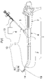
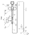
- FIG. 1 is a diagram for explaining an endoscope including an endoscopic treatment tool according to Embodiment 1 of the present invention; It is a figure showing the whole treatment implement for endoscopes by Embodiment 1 of the present invention.
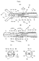
- FIG. 3A is a diagram for explaining the front appearance of the endoscopic treatment instrument according to Embodiment 1 of the present invention
- FIG. 3B is a front external view, omitting the sheath, showing a state in which a pair of treatment pieces are closed
- 4(A) is a front cross-sectional view of the distal end portion of the treatment instrument with the treatment piece opened;
- FIG. 4(B) is a front cross-sectional view of the distal end portion of the treatment instrument with the treatment piece closed
- FIG. 4(C) is a cross-sectional view IVc-IVc in FIG. 4(B)
- FIG. B) is a cross-sectional view taken along IVd-IVd
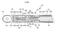
- FIG. 3B is a side cross-sectional view of the endoscopic treatment instrument according to Embodiment 1 of the present invention, and is a cross-sectional view taken along the line VV in FIG. 3B.
- FIG. 6A is a diagram for explaining the flow of the treatment liquid ejected from the endoscopic treatment instrument according to Embodiment 1 of the present invention
- FIG. 6B is a diagram showing a state in which liquid flowing inside the treatment section support member flows out from the distal end of the treatment section support member
- FIG. FIG. 6(C) is a view showing a state in which the liquid flowing through the treatment section supporting member flows out from the distal end of the treatment section support member
- FIG. It is a figure which shows the state which flows out from the front-end
- FIG. 10 is a diagram for explaining a front cross-section of the endoscopic treatment instrument according to Embodiment 2 of the present invention
- FIGS. 8A and 8B are diagrams for explaining a treatment portion supporting member of a treatment instrument for an endoscope according to Embodiment 3 of the present invention, FIG. 8A being an overall perspective view
- FIG. 8A being an overall perspective view
- FIG. 10 is a cross-sectional view for explaining the structure and operation of the link mechanism of the endoscope treatment instrument according to Embodiment 3 of the present invention
- FIG. 11 is a perspective view showing the appearance of a link mechanism of a treatment instrument for an endoscope according to Embodiment 3 of the present invention
- FIG. 10 is a diagram for explaining the principle of the link mechanism of the endoscope treatment instrument according to Embodiment 3 of the present invention
- an embodiment of an endoscopic treatment instrument according to the present invention will be described below with reference to the drawings.
- the side on which the treatment section is located is called the distal end side
- the side on which the operation section is located is called the rear end side.
- FIG. 1 is a diagram showing an endoscope 1 to which an endoscopic treatment device according to Embodiment 1 is applied.
- This endoscope 1 has an elongated insertion section 2 for insertion into a body cavity of a living body, and a dial provided on the rear end side for bending the distal end of the insertion section 2 vertically and horizontally. and a treatment instrument introduction part 4 which is arranged to connect between the insertion part 2 and the endoscope operation part 3 and has an insertion opening for inserting the treatment instrument 10 for an endoscope.
- This endoscope 1 has a cylindrical endoscope channel 5 formed in the longitudinal direction from the treatment instrument introduction portion 4 toward the distal end of the insertion portion 2. In this endoscope channel 5, a A sheath 11 having a pair of treatment pieces 15 and 16 for treating an affected part of a living body of the treatment instrument 10 for an endoscope attached to the distal end thereof is inserted through the sheath 11 .
- the endoscopic treatment instrument 10 is composed of a pair of treatment pieces 15 and 16 which are cup-shaped forceps for performing electrical cauterization by sandwiching a treated portion (affected portion) of a living tissue in a body cavity.
- a treatment unit is provided.
- a treatment liquid is sent through the sheath 11 from the liquid feeding means 6 and jetted forward of a pair of treatment pieces 15, 16 to treat a body tissue to be treated (affected part) in a body cavity. can be washed.
- the pair of treatment pieces 15 and 16 is not limited to electrocautery cup-shaped forceps.
- the endoscopic treatment instrument 10 is an elongated flexible tubular sheath. 11, an operation wire 12 penetrating the sheath 11, an operation portion 13 connected to the rear end side of the operation wire 12, and connected to the front end side of the operation wire 12 via an advance/retreat transmission rod 17 and a link mechanism. and a treatment portion support member 14 attached to the distal end side of the sheath 11 via a rotatable connecting portion 19 and supporting the treatment portion 90 .
- a base end side connecting cylindrical portion 20 and a distal end side connecting cylindrical portion 23 are rotatably connected.
- the treatment section 90 is composed of a pair of treatment pieces 15 and 16 that are opened and closed by a pair of drive links 15d and 16d and opening/closing links 15b and 16b. Thereby, the treatment pieces 15 and 16 are configured to be opened and closed via the link mechanism.
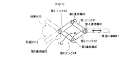
- the link mechanism according to this embodiment is a pantograph-type four-bar link mechanism, one end of which is connected by a fourth connecting shaft 85 (pair) connected to the forward/retreat transmission rod 17 that performs linear motion.
- a first link 81 and a second link 82 (referred to as a "pair of driving links") rotatably overlapped and connected, and the other end and one end of the first link 81 and the second link 82 are respectively connected to the second link.
- a third link 83 and a fourth link 84 are rotatably connected by a connecting shaft 86 and a third connecting shaft 87, and the other end is rotatably connected by a positionally fixed first connecting shaft 88. (referred to as "a pair of opening and closing links”), so that the overlapping width of the first link 81 to the fourth link 84 and the gap between the pair of arms of the treatment section support member are substantially the same.
- the fourth connecting shaft 85 serves as a force point for the pair of drive links
- the first connecting shaft 88 serves as a fulcrum for the pair of opening/closing links
- the pair of opening/closing links , the treatment piece 16 extending from the other end of the third link 83 and the treatment piece 15 extending from the other end of the fourth link 84 are configured to open and close.
- Reference numeral 14z in FIG. 11 denotes a stopper, which will be described later.
- the link mechanism employed in this embodiment includes a pair of opening/closing links (the third link 83 and the fourth link) which extend the treatment pieces 15 and 16 from one end and are rotatably connected by the first connecting shaft 88. 84), one end of which is connected to the other end of the pair of opening/closing links by a second connecting shaft 86 and a third connecting shaft 87, and the other end of which is rotatably connected by a fourth connecting shaft 85.
- link (first link 81 and second link 82), and forward/backward movement transmission rod 17 that receives forward/backward motion force of the operation wire on fourth connecting shaft 85 of the drive link, and forward/backward transmission rod 17 is provided.
- a pair of treatment pieces 15 and 16 extending from an opening/closing link are configured to be opened and closed by moving the rod 17 forward and backward.
- the endoscopic treatment instrument 10 has a hydrophilic coating formed on at least the outer surface of the portion of the sheath 11 to be inserted into the body cavity and the outer surface of the treatment portion supporting member 14, thereby forming treatment pieces 15 and 16. to the sheath 11 can be smoothly introduced into the body cavity without twitching.
- the sheath 11 has the flexibility to be inserted into and removed from the endoscope channel 5 by covering a resin outer covering 11b on a coil sheath 11a that is tightly wound into a long coil.
- the sheath 11 is an elongated tubular body having a length of, for example, 500 to 2600 mm, flexibility and moderate stiffness (bending resistance).
- the sheath 11 of this embodiment is composed of a coil sheath 11a and a resin jacket 11b covering the outer surface of the coil sheath 11a.
- As the coil sheath 11a it is preferable to use a coil sheath in which a metal material such as a stainless steel wire having a rectangular cross section is closely contacted and coiled.
- the resin jacket 11b is made of PTFE, PEEK, PPS, polyethylene, polyimide, or the like, and has flexibility and electrical insulation.
- the hydrophilic coating is overlaid on the electrically insulating coating.
- the sheath 11 has an electrical insulating coating formed on the inner surface of the coil sheath 11a and the outer surface of the treatment portion support member 14. As shown in FIG. An electrical insulating coating may be formed on the inner and outer surfaces of the coil sheath 11a without providing the resin outer covering 11b.
- the operation wire 12 is a torque wire that is disposed in the coil sheath 11a so as to be able to move back and forth, is conductive, and has a high rotational followability.
- the operation wire 12 may be, for example, made entirely of stainless steel, or may have a rear end made of stainless steel and a front end made of nitinol (nickel-titanium alloy) connected by a stainless steel pipe.
- the operation portion 13 includes an operation portion main body 13a for operating the opening/closing and rotation of the treatment piece, a slider 13b slidable relative to the operation portion main body 13a, and a front end of the operation portion main body 13a.
- the operation unit 13 has a liquid injection port (liquid supply connection port) 13c2 provided at the rear end of the coil sheath 11a for injecting the treatment liquid into the coil sheath 11a. It is a mechanism for doing so.
- the operation unit main body 13a includes a long rectangular frame portion 13a1 having a long rectangular frame shape having linear guides on two rows of side surfaces for guiding linear movement, and a rear end side of the long rectangular frame portion 13a1. and a handle portion 13a2 having a circular frame-shaped finger hooking hole 13a4 for the operator to put his or her finger on, and a male mold extending to the tip side of the long rectangular frame portion 13a1 and screwed to the liquid injection portion 13c. and a connecting portion 13a3.
- the conical male connection portion 13a3 has a through hole through which the operation wire 12 passes.
- the slider 13b has finger hook holes 13b1 and 13b2 (feathers) for hooking the operator's fingers, and the central part is slidably fitted in the linear guide of the long rectangular frame part 13a1.
- the palm is widened or narrowed so as to be slidable along the linear guide of the long rectangular frame portion 13a1.
- the rear ends of the operation wire 12 and the coil sheath 11a are integrally rotatably connected. Therefore, by holding the slider 13b and rotating it around the rectangular frame portion 13a1 to rotate the operation wire 12 and the sheath 11 integrally, the sheath 11 and the operation wire 12 are integrally rotated on the distal end side of the sheath 11. can do.
- a holding portion is provided to separate the male connection portion 13a3 from the long rectangular frame portion 13a1 so that it does not rotate.
- the liquid injection portion 13c includes a through hole 13c1 extending through the interior in the longitudinal direction, a liquid injection port 13c2 connected to the middle of the through hole 13c1, and a male connection portion of the operation portion main body 13a formed at the rear end side of the through hole 13c1. It has a conical female threaded portion (no sign) screwed to 13a3 and a conical male threaded portion (no sign) formed at the tip side of the through hole 13c1 and screwed to the connection cap 13d.
- the liquid feeding means 6 is connected to the liquid injection port 13c2.
- the liquid sending means 6 is a syringe, a pump, or the like, and can send treatment liquid such as physiological saline or hyaluronic acid into the coil sheath 11a.
- the operation wire 12 inserted into the sheath 11 is inserted through the connection cap 13d, the through hole 13c1 of the liquid injection portion 13c, and the through hole of the operation portion main body 13a, and the rear end of the operation wire 12 is inserted into the long rectangular frame portion. It is passed through the frame of 13a1 and connected to the slider 13b.
- a liquid seal ring (not shown) is provided so as to fill an annular gap on the rear end side of the through hole between the operation wire 12 and the operation portion main body 13a.
- the rear end side of the sheath 11 is flared against the tip side of the liquid injection part 13c and fixed by the connection cap 13d.
- the liquid supplied from the liquid delivery means 6 is sent to the distal end side of the sheath 11 through the space around the operation wire 12 in the sheath 11 from the liquid inlet 13c2.
- the treatment section support member 14 is connected to the distal end of the coil sheath 11a via a rotatable connection section 19, which will be described later, and has a lid with one open surface closed. It has a cylindrical portion 14a and a pair of arm portions 14b, 14b extending from the cylindrical portion 14a toward the distal end side.
- the treatment portion supporting member 14 has an electrically insulating coating formed on the outer surface, and a hydrophilic coating is formed thereon.
- the treatment pieces 15 and 16 and the opening/closing links (the third link 83 and the fourth link 84 in FIG. 11) according to this embodiment are made of stainless steel, nitinol (nickel-titanium alloy), or the like. It constitutes a pair of biopsy forceps.
- a portion where one ends of the pair of opening/closing links 15b and 16b that overlap and intersect are connected by a first connecting shaft is called an intersection portion. Since the treatment piece is configured to extend in the distal direction, when the rear end portions of the treatment piece are overlapped and intersected, the rear end portion can also be called a crossing portion.
- the treatment pieces 15 and 16 are configured such that the distal ends of the treatment pieces 15 and 16 are in contact with the semicircular blade portion and the linear blade portion following the semicircular blade portion are in contact with each other. Since it is in an insulated state, as shown in FIG. 3B, a current flows between the blades when the blades are closed together. A pair of treatment pieces 15 and 16 are formed over the hydrophilic coating and the electrically insulating coating.
- the crossing portions 15a and 16a are crossed and overlapped in an X shape between the pair of arm portions 14b and 14b, and are provided with shaft holes.
- the pair of treatment pieces 15 and 16 are supported by the pair of arms 14b and 14b by inserting the first connecting shaft 18 supported at both ends into the support holes 18x (see FIG. 8) of the arms 14b and 14b. ing.
- the treatment portion support member 14 includes an opening/closing link (third link 83 and fourth link 84 in FIG. 11) that connects one end so as to be rotatable about a first connecting shaft 88, and the pair of opening/closing links.
- a link mechanism composed of a pair of driving links (first link 81 and second link 82) connected by the other end of and a second connecting shaft 86 and a third connecting shaft 87 is supported, and from the opening and closing link
- a treatment portion is formed by extending the treatment pieces 15 and 16 .
- the treatment portion support member 14 includes an opening/closing link 15b corresponding to the opening/closing link (the third link 83 and the fourth link 84 in FIG. 11) explained in the principle diagram.
- 16b are thinly formed with steps to overlap each other and pin holes are formed, and the opening/closing links 15b, 16b are pin-connected to the tip portions having the pin holes of the pair of driving links 15d, 16d, respectively (the first link in FIG. 11). are connected by two connecting shafts 86 and a third connecting shaft 87).
- the distal end portion of the forward/backward movement transmission rod 17 is also formed thin and has a pin hole. (connected to the fourth connecting shaft 85 in FIG. 11).
- An electrical insulating coating is formed on the outer surfaces of the pair of driving links 15d and 16d.
- the rear end portion of the forward/retreat transmission rod 17 and the distal end portion of the operation wire 12 are connected by inserting the distal end portion of the operation wire 12 into a wire receiving hole provided inside the rear end surface of the forward/retreat transmission rod 17 .
- the connection is fixed by screwing a tightening screw into a female thread provided on the side of the wire receiving hole 17 .
- This connection and fixation may be silver brazing, soldering, caulking, or the like.
- the pair of treatment pieces 15 and 16 are opened and closed by the operator's forward/backward operation of the operation wire 12, and when the blades are closed, the normal portion of the living tissue and the affected portion are separated by the blade portion.
- the treated area By inserting the affected area into the cup across the dividing line from the treated area (affected area) and performing electrocautery accompanied by hemostatic action, the treated area can be excised, sampled, or otherwise treated.
- the endoscopic treatment instrument 10 includes a tubular portion 14a of a treatment portion supporting member 14 and a The coil sheath 11a is connected via a rotatable connecting portion 19. As shown in FIG.
- the rotatable connecting portion 19 has a two-stage cylindrical shape including a base end side connecting cylindrical portion 20 having a cylindrical coil cap 21 and a connecting cylindrical portion 22, and a large diameter cylindrical portion 23a and a small diameter cylindrical portion 23b. and a distal end side connecting tubular portion 23 fixed to the rear end portion of the tubular portion 14 a of the treatment portion supporting member 14 . is fitted to the connecting small-diameter cylindrical portion 22a of the connecting cylindrical portion 22 so as to be relatively rotatable and non-separable.
- the base end side coupling tubular portion 20 is composed of two parts, a tubular coil cap 21 and a coupling tubular portion 22 .
- the tubular coil cap 21 includes a thin tubular portion 21 a fitted and fixed to the distal end portion of the sheath 11 and a thick tubular portion having the same inner diameter as the inner diameter of the sheath 11 and having an inner end in contact with the distal end portion of the sheath 11 .
- the outer peripheral surfaces of the thin cylindrical portion 21a and the thick cylindrical portion 21b are aligned with each other, and the outer diameter is set to be the same as that of the cylindrical portion 14a of the treatment portion support member 14. As shown in FIG.
- the connecting tube portion 22 has a connecting small-diameter tube portion 22a and a collar portion 22b provided on the distal end side of the connecting small-diameter tube portion 22a and slidably fitted into the tube portion 14a.
- Approximately half of the tubular portion 22a is fitted into the thick tubular portion 21b of the tubular coil cap 21, and the insertion end is fixed by welding, brazing, or the like, and the remaining approximately half portion is the thick tubular portion of the tubular coil cap 21. It protrudes from the portion 21b.
- the distal end-side connecting cylindrical portion 23 includes a large-diameter cylindrical portion 23a having the same outer diameter as the cylindrical portion 14a of the treatment portion support member 14 and is connected and fixed in the direction of the sheath 11 from the cylindrical portion 14a, and a large-diameter cylindrical portion 23a.
- a small-diameter tubular portion 23b extending forward from the tubular portion 23a and fitted into the tubular portion 14a is provided.
- the large-diameter cylindrical portion 23a and the small-diameter cylindrical portion 23b have the same inner diameter, and are slidably fitted to the connecting small-diameter cylindrical portion 22a of the connecting cylindrical portion 22.
- the large-diameter cylindrical portion 23a is connected to the cylindrical portion 14a by welding, brazing, or the like at the abutting end surfaces thereof.
- the rotatable connecting portion 19 allows the operation wire 12 to rotate with respect to the sheath 11 without restriction.
- the rotatable connecting portion 19 has an electrically insulating film formed on its outer surface, and a hydrophilic film is formed thereon.
- the treatment liquid fed through the coil sheath 11a is supplied to the pair of arm portions 14b, 14b. It has the configuration described below in order to jet vigorously forward from the tip.
- the treatment portion support member 14 includes a through hole 14h opened in an inner convex wall 14g of a cylindrical portion 14a on the proximal side of the treatment portion support member 14, and oval liquid feeding portions 14h1 and 14h2 [FIG. 4(D)], curved inner wall surfaces (concave portions 14c, 14d) of a pair of arcuate arm portions 14b extending toward the distal end of the treatment portion support member 14, and driving actuators disposed between the pair of arm portions 14b.
- Treatment liquid supply for circulating the treatment liquid through the gap between the intersection 15a (or 16a) of the link 15d (or 16d) and the treatment piece 15 (or 16) and the outer surface of the opening/closing link 15b (or 16b) It constitutes the transmission paths 14e and 14f [FIG. 4(C)].
- These treatment liquid supply paths 14e and 14f are wider than the diameter of the connection shaft (first connection shaft) that connects the opening/closing links 15b and 16b, and the treatment liquid flows through the connection shaft (first connection shaft). It is formed so that it flows straight on both sides of the .
- the treatment portion support member 14 has the outer surface of the cylindrical portion 14a and the outer surfaces of the respective concave portions 14c and 14d, which are cylindrical surfaces whose centers of curvature coincide with the center line of the extension of the operation wire 12.
- the inner surfaces of the concave portions 14 c and 14 d are also concave cylindrical surfaces formed so that the center of curvature coincides with the extended center line of the operation wire 12 .
- the shape of the liquid feeding portion 14h1 opening in the inner convex wall 14g is oblong.
- a liquid feeding part may be formed by opening a hole for circulating the treatment liquid separately from the hole for passing the treatment liquid.
- the treatment portion support member 14 has a pair of arm portions 14b, 14b on both sides of the concave portions 14c, 14d on the inner surfaces thereof in order to form the above-described structure.
- the dimension of the gap between the edges are Match.
- planar side surfaces 15a1 or 16a1 on the outer side of the intersecting portion 15a or 16a of each treatment piece 15 or 16 are in slidable contact (rubbing) with the opposite side edge portions of the opposing surfaces of the arm portions 14b across the concave portions 14c and 14d. while touching).
- the cylindrical portion 14a of the treatment portion support member 14 has an inner convex wall 14g through which the forward/backward movement transmission rod 17 is inserted and guided.
- An elongated elliptical through hole 14h is provided, and the through hole 14h is provided with a pair of liquid feeding portions 14h1 and 14h2 for causing the treatment liquid supplied through the coil sheath 11a to flow to the center of the width of each of the concave portions 14c and 14d.
- the concave surface portion 14c (or 14d) formed on the inner surface of each arm portion 14b and the crossing portion 15a (or 16a) on the same side as the one arm portion 14b are connected to the opening/closing link 15b (or 16b). and side portions of a pair of drive links 15d (or 16d) form treatment liquid supply paths 14e and 14f.
- the through-hole 14h of this embodiment is open in the shape of an oblong hole that is elongated in the facing direction of the pair of arm portions 14b and 14b so as to have a pair of liquid feeding portions 14h1 and 14h2.
- the outer surfaces of the pair of drive links 15d (or 16d) correspond to the width center portion of the concave surface portion 14c (or 14d) of the arm portion 14b on the same side. Since there is sliding contact (a state of contact while rubbing), the treatment liquid flowing from the inside of the cylindrical portion 14a into the center portion of the width of the concave portion 14c (or 14d) flows straight due to the action of water supply pressure and surface tension, Since the flow path resistance increases in the width direction of the concave surface portion 14c (or 14d), the amount of leakage from the gap between the arm portions 14b, 14b is small, and the air is ejected from the inside of the tips of the pair of arm portions 14b, 14b. is made to
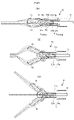
- FIGS. 6A and 6B show a state in which the endoscopic treatment instrument 10 according to the present embodiment ejects the treatment liquid fed inside the coil sheath 11a from the distal end of the treatment portion 90 toward the distal direction. ) and (C).
- the endoscopic treatment instrument 10 is configured such that when the treatment liquid is fed with the treatment pieces 15 and 16 closed, the pair of treatment liquid supply paths 14e , 14f (tips of the pair of arms 14b, 14b) wraps the treatment pieces 15, 16 in a closed state due to surface tension (as indicated by the dashed line), and the velocity of the single line increases. It becomes a liquid stream and erupts forward vigorously. That is, the endoscopic treatment instrument 10 is provided with the pair of treatment liquid supply paths 14e and 14f of the treatment section support member 14, so that the liquid supply pressure can be maintained up to the intersections 15a and 16a, and at the same time, the liquid supply can be controlled.
- the liquid to be treated can be fed along the pair of treatment pieces 15 and 16 in a necessary and sufficient amount and at a sufficient flow rate into the body cavity. It can be ejected accurately to the treated area (incision affected area or bleeding site).
- the endoscopic treatment instrument 10 is opened to a middle opening state by inserting the treatment pieces 15 and 16 into the vicinity of the part to be treated in the body vagina.
- the treatment liquid is fed in this state, the liquid to be treated flowing out from the tips of the pair of treatment liquid supply paths 14e and 14f flows as two liquid streams along the treatment pieces 15 and 16 due to surface tension, It spouts so that it becomes one liquid stream in front.
- the endoscopic treatment instrument 10 when the treatment liquid is supplied while the treatment pieces 15 and 16 are opened to the maximum degree of opening, a pair of treatment
- the liquid to be treated flowing out from the tips of the liquid supply paths 14e and 14f flows vigorously forward along both outer surfaces of the treatment pieces 15 and 16 due to surface tension. It spouts so that it becomes one liquid stream that flows vigorously forward through the fan-shaped center.
- the endoscopic treatment instrument 10 when the treatment pieces 15 and 16 are opened to the maximum degree of opening, for example, when the treatment pieces 15 and 16 spread the treated portion in the body cavity,
- the liquid to be treated can be accurately ejected in a necessary and sufficient amount and at a sufficient flow rate to the entire area of the expanded treated area.
- the endoscopic treatment instrument 10 can be used with the pair of treatment pieces 15 and 16 closed.
- the physiological saline solution (treatment liquid) is sent by the liquid feeding means 6 while being brought close to the site to be treated of the living body, the treatment liquid can flow out from the distal end of the treatment portion support member 14 in a straight line.
- the pair of treatment pieces 15 and 16 of the endoscopic treatment instrument 10 is slowly opened, the liquid splits into two from the distal end of the treatment portion support member 14 and opens, causing bleeding, stagnation, Turbidity can be flushed off to both sides.
- the endoscopic treatment instrument 10 repeats the opening and closing of the pair of treatment pieces 15 and 16 as necessary, and the physiological saline flowing out from the distal end of the treatment portion support member 14 flows in one straight line and two lines. By repeating the flow that divides and opens, bleeding, stagnation, and turbidity can be washed away more effectively to both sides, which can greatly contribute to treatment.
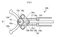
- FIG. 7 is a diagram for explaining the front appearance of the endoscopic treatment instrument 10A according to the second embodiment.
- the endoscopic treatment instrument 10A according to the present embodiment is an incision scissors for performing electrocautery for an endoscope, in which a pair of treatment pieces 15A and 16A sandwich a living tissue in a body cavity and apply a required electric current. An incision is made while cauterizing the living tissue and stopping bleeding.
- the endoscopic treatment instrument 10A includes a sheath 11, an operation wire 12, an operation portion 13, a treatment portion support member 14, and a pair of treatment pieces 15A and 15A, which are features of the present embodiment. and a treatment section 91 consisting of 16A.
- concave portions are formed on the inner surfaces of the arm portions 14b, 14b of the treatment portion support member 14.
- Treatment liquid supply paths are formed between the arms 14b, 14b and the treatment pieces 15A, 16A, and the tubular portion 14a is formed with an inner convex wall 14g having a through hole 14h for guiding the forward/backward movement transmission rod.
- the through hole 14h has a pair of liquid feeding portions similar to the pair of treatment liquid feeding paths 14e and 14f shown in FIG. 4(C).
- the flow of the treatment liquid is the same as in FIGS. 6(A), (B), and (C).
- the endoscopic treatment instrument 10A includes a treatment section 91 comprising treatment pieces 15A and 16A, which are a pair of scissor pieces with widened distal ends. Incision excision of the affected area is performed by sandwiching the affected area and energizing the affected area. The liquid to be treated can be ejected accurately at a flow rate.
- the treatment portion support member 14A is connected to the distal end portion of the coil sheath 11a described above via a rotatable connection portion 19, and as shown in FIGS.
- a cylindrical portion 14a having an oblong liquid feeding portion that penetrates the forward/backward movement transmission rod 17 is opened, and a first connecting shaft 18 is rotatably attached to the distal end portion of the cylindrical portion 14a.
- a forward/backward movement transmission rod 17 having a portion 17a is provided.
- the arm portion 14b of the treatment portion support member 14A receives forward/retreat force from the forward/retreat transmission rod 17 at the edge portion of the middle portion of the arm portion.
- a triangular first stopper 14z is provided for limiting the maximum opening angle of the pair of treatment pieces when the drive link in the open state abuts against it, and particularly FIG. 8(d)(x) and FIG.
- the circumferential portion of the inner convex wall of the tubular portion 14a is provided with a groove for abutting against the wide bottom surface (base end side surface) of the fistbone-shaped distal end portion 17a for limiting the minimum opening angle of the pair of treatment pieces.
- a second stopper 14x is provided.
- the first stopper 14z is not limited to a triangular shape, and may have a circular shape or other shape.
- the stopper for limiting the maximum opening angle is not limited to being placed in the middle of the arm, and may be placed on the tip side of the arm to widen the opening angle.
- the stopper 14z limits the maximum opening angle of the pair of treatment pieces by abutting against the drive link when the forward/backward movement transmission rod 17 moves to the distal side and limiting the range of movement to the distal side. do.
- the stopper 14x has a short diameter of a predetermined value of the liquid feeding portion so that when the forward/backward movement transmission rod 17 moves to the rear end side, it abuts against the wide bottom surface of the fist-shaped distal end portion 17a to limit the range of movement to the rear end side. limit the minimum closing angle of the pair of treatment pieces.
- the stopper 14x is not limited to this example, and may be arranged so as to come into contact with the narrow portion of the concave portion inside the arm portion.
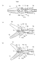
- the endoscopic treatment instrument according to Embodiment 3 configured as described above includes a pair of driving links whose one ends are rotatably overlapped and connected by a connecting shaft 73 connected to the advancing/retreating transmission rod 17 that performs linear motion. 50d and 51d, and the other end and one end of the drive links 50d and 51d are rotatably connected by connecting shafts 71 and 72, respectively, and fixed in position.
- a link mechanism is constituted by a pair of opening/closing links 50b and 51b that are connected together, and a pair of treatment pieces 50 and 51 extending from the opening/closing links 50b and 51 are connected as shown in FIG. As shown in FIG.
- the forward/retreat transmission rod 17 is moved slightly toward the distal end from the closed state when the rod 17 is pulled toward the rear end side, and becomes slightly open about the support shaft 18. Further, as shown in FIG. 9(c), the forward/backward movement transmission rod 17 is moved to the distal end side and is opened to the maximum opening angle.
- This maximum opening angle is the maximum angle at which the driving link 50d hits the stopper 14z and restricts its movement. , is restricted by the driving link 50d coming into contact with the stopper 14z.
- the stopper 14z may be arranged at a position that regulates the opening/closing angle of the opening/closing link.
- the reason for limiting the maximum opening angle of the treatment piece of this endoscopic treatment instrument is as follows. As a doctor's opinion, when performing incisional dissection collection using high frequency in a narrow range (large intestine, small intestine, duodenum and bile duct, ureter, esophagus, etc.), do not place near the end face of the endoscope. The treatment area is positioned and the treatment is performed with the field of view expanded. For this reason, the endoscopic treatment instrument has a problem that if the maximum opening angle of the treatment piece is large, the field of view of the doctor is blocked, and if the treatment piece is opened wide, one of the treatment pieces becomes invisible from the field of view.
- the forward/backward movement transmission rod 17 is pulled toward the rear end side, and the wide bottom surface of the fist bone-shaped distal end portion 17a of the forward/backward movement transmission rod 17 hits the stopper 14x to restrict the movement. minimum angle.
- the reason for limiting the minimum closing angle of the treatment piece of this endoscopic treatment instrument is as follows. In endoscopic treatment tools that close scissors-shaped treatment pieces, if the blades close too much and the blades cross each other, the lesion may be seized and the blades may not open. This is because it is required that the parts be closed without crossing, and when the endoscope is moved into and out of the channel, the blade that crosses too far may damage the inner wall of the channel, and this is to be prevented.
- the endoscopic treatment instrument has a tube portion 14a having an oblong liquid feeding portion opened on the inner convex wall and an arc shape extending from the tube portion reference numeral 14a to the distal end side.
- a treatment portion support member 14A having a pair of extending arms 14c is provided.
- a treatment portion supporting member 14A is provided with a long tubular advance/retreat transmission rod provided with a fist-shaped distal end portion and a four-joint link mechanism in the same manner as in the above-described embodiment.
- a four-bar link mechanism is configured to open and close a pair of treatment pieces.
- the endoscopic treatment instrument has a stopper 14z for restricting the movement of the drive link in the distal direction at the middle portion of the pair of arms 14b, and a knuckle of the forward/retreat transmission rod 17 at the cylindrical portion 14a.
- the maximum and minimum opening and closing angles of the treatment piece 15 and the treatment piece 16 are restricted by providing the stopper 14x against which the wide bottom surface of the shaped distal end portion 17a abuts.
- concave portions are formed on the inner surfaces of the arm portions of the treatment portion supporting member, so that the arm portions (plurality) are The arcuate inner wall and the side surface of the link mechanism rub against each other to form a treatment liquid supply path.
- the treatment liquid can be jetted along the treatment piece in the same manner as shown in 6.
- a cylindrical portion having an opening in the inner convex wall of the liquid feeding portion through which the forward/backward movement transmission rod penetrates and a pair of arms extending in an arc shape from the cylindrical portion toward the distal end side are provided. and a four-joint link mechanism disposed between a pair of arms of the treatment section support member in sliding contact with each other and configured to open and close the pair of treatment pieces by a four-joint link connection. 6, the treatment liquid flowing out from the cylindrical portion is supplied to the treatment liquid in the same manner as shown in FIG. can be jetted along the treatment strip.
- the treatment liquid supply path is provided on the inner surface side of the pair of arms of the treatment section support member, and the treatment liquid fed through the sheath is provided from the tubular section of the treatment section support member to the arms.
- the liquid feeding pressure is maintained up to the intersection of the pair of opening/closing links so as to feed the treatment liquid in the center of the width of the treatment liquid feeding path. Since the treatment liquid can be smoothly delivered from the treatment liquid supply path on the inner surface side of the pair of arms, the liquid to be treated can be fed along the pair of treatment pieces in a necessary and sufficient amount and at a sufficient flow rate. can be provided.
- connection cap 14 Treatment portion support member 14a Tube portion 14b Arm portion 14c, 14d Concave portion 14e, 14f ... treatment liquid supply path, 14g ... inner convex wall, 14h ... through hole, 14h1, 14h2... solution sending part, 15, 16... treatment piece, 15a, 16a... Crossing portion, 15a1, 16a1... Planar side surface portion, 15b, 16b... opening/closing links, 15, 16... treatment pieces, 15d, 16d drive link 17 advance/retreat transmission rod 18 first connecting shaft 19 rotatable connecting portion 20 proximal side connecting cylindrical portion 21 cylindrical coil cap 21a thin cylindrical portion 21b thick cylindrical portion 22 connecting cylindrical portion 22a... Small-diameter tube portion for connection, 22b... Collar portion, 23... Tip-side connection tube portion, 23a... Large-diameter tubular portion, 23b... Small-diameter tubular portion
Landscapes
- Health & Medical Sciences (AREA)
- Life Sciences & Earth Sciences (AREA)
- Surgery (AREA)
- Engineering & Computer Science (AREA)
- Veterinary Medicine (AREA)
- Molecular Biology (AREA)
- Nuclear Medicine, Radiotherapy & Molecular Imaging (AREA)
- Public Health (AREA)
- Biomedical Technology (AREA)
- Heart & Thoracic Surgery (AREA)
- Medical Informatics (AREA)
- General Health & Medical Sciences (AREA)
- Animal Behavior & Ethology (AREA)
- Otolaryngology (AREA)
- Plasma & Fusion (AREA)
- Physics & Mathematics (AREA)
- Ophthalmology & Optometry (AREA)
- Biodiversity & Conservation Biology (AREA)
- Pathology (AREA)
- Surgical Instruments (AREA)
Priority Applications (5)
| Application Number | Priority Date | Filing Date | Title |
|---|---|---|---|
| EP22811272.8A EP4302710A4 (en) | 2021-05-25 | 2022-05-23 | ENDOSCOPIC TREATMENT DEVICE |
| JP2023523457A JP7492085B2 (ja) | 2021-05-25 | 2022-05-23 | 内視鏡用処置具 |
| US18/285,452 US20240189013A1 (en) | 2021-05-25 | 2022-05-23 | Treatment instrument for endoscopes |
| CN202280030693.1A CN117241749A (zh) | 2021-05-25 | 2022-05-23 | 内窥镜用处置器具 |
| KR1020237042936A KR20240007259A (ko) | 2021-05-25 | 2022-05-23 | 내시경용 처치구 |
Applications Claiming Priority (2)
| Application Number | Priority Date | Filing Date | Title |
|---|---|---|---|
| JP2021-087785 | 2021-05-25 | ||
| JP2021087785 | 2021-05-25 |
Publications (1)
| Publication Number | Publication Date |
|---|---|
| WO2022250002A1 true WO2022250002A1 (ja) | 2022-12-01 |
Family
ID=84228761
Family Applications (1)
| Application Number | Title | Priority Date | Filing Date |
|---|---|---|---|
| PCT/JP2022/021059 Ceased WO2022250002A1 (ja) | 2021-05-25 | 2022-05-23 | 内視鏡用処置具 |
Country Status (6)
| Country | Link |
|---|---|
| US (1) | US20240189013A1 (cg-RX-API-DMAC7.html) |
| EP (1) | EP4302710A4 (cg-RX-API-DMAC7.html) |
| JP (1) | JP7492085B2 (cg-RX-API-DMAC7.html) |
| KR (1) | KR20240007259A (cg-RX-API-DMAC7.html) |
| CN (1) | CN117241749A (cg-RX-API-DMAC7.html) |
| WO (1) | WO2022250002A1 (cg-RX-API-DMAC7.html) |
Families Citing this family (1)
| Publication number | Priority date | Publication date | Assignee | Title |
|---|---|---|---|---|
| KR20260026157A (ko) * | 2024-08-19 | 2026-02-26 | 고신대학교 산학협력단 | 말초 기관지 병변 처치를 위한 가이드 시스의 사이드 튜브 |
Citations (4)
| Publication number | Priority date | Publication date | Assignee | Title |
|---|---|---|---|---|
| JP2005319164A (ja) * | 2004-05-11 | 2005-11-17 | Olympus Corp | 内視鏡用処置具 |
| WO2014155743A1 (ja) * | 2013-03-29 | 2014-10-02 | 国立大学法人 東京工業大学 | 鉗子 |
| WO2017134757A1 (ja) | 2016-02-02 | 2017-08-10 | オリンパス株式会社 | 内視鏡処置具 |
| WO2017134752A1 (ja) * | 2016-02-02 | 2017-08-10 | オリンパス株式会社 | 内視鏡処置具 |
Family Cites Families (10)
| Publication number | Priority date | Publication date | Assignee | Title |
|---|---|---|---|---|
| DE3581665D1 (de) * | 1984-05-18 | 1991-03-14 | Harald Maslanka | Chirurgisches greiferinstrument. |
| US4671445A (en) * | 1984-08-09 | 1987-06-09 | Baxter Travenol Laboratories, Inc. | Flexible surgical stapler assembly |
| US20030187349A1 (en) * | 2002-03-29 | 2003-10-02 | Olympus Optical Co., Ltd. | Sentinel lymph node detecting method |
| JP4131014B2 (ja) * | 2003-03-18 | 2008-08-13 | Hoya株式会社 | 内視鏡用嘴状処置具 |
| CA2439536A1 (en) * | 2003-09-04 | 2005-03-04 | Jacek Krzyzanowski | Variations of biopsy jaw and clevis and method of manufacture |
| WO2007017949A1 (ja) * | 2005-08-11 | 2007-02-15 | Olympus Corporation | 内視鏡用処置具 |
| US7824406B2 (en) * | 2006-12-28 | 2010-11-02 | St. Jude Medical, Atrial Fibrillation Division, Inc. | Irrigated ablation catheter having a valve to prevent backflow |
| JP5437778B2 (ja) * | 2009-11-30 | 2014-03-12 | 朝日インテック株式会社 | 医療用処置具 |
| US8939972B2 (en) * | 2011-05-06 | 2015-01-27 | Covidien Lp | Surgical forceps |
| CN104869921B (zh) * | 2013-05-17 | 2017-03-15 | 奥林巴斯株式会社 | 内窥镜处理器具 |
-
2022
- 2022-05-23 WO PCT/JP2022/021059 patent/WO2022250002A1/ja not_active Ceased
- 2022-05-23 CN CN202280030693.1A patent/CN117241749A/zh active Pending
- 2022-05-23 KR KR1020237042936A patent/KR20240007259A/ko active Pending
- 2022-05-23 JP JP2023523457A patent/JP7492085B2/ja active Active
- 2022-05-23 EP EP22811272.8A patent/EP4302710A4/en active Pending
- 2022-05-23 US US18/285,452 patent/US20240189013A1/en active Pending
Patent Citations (4)
| Publication number | Priority date | Publication date | Assignee | Title |
|---|---|---|---|---|
| JP2005319164A (ja) * | 2004-05-11 | 2005-11-17 | Olympus Corp | 内視鏡用処置具 |
| WO2014155743A1 (ja) * | 2013-03-29 | 2014-10-02 | 国立大学法人 東京工業大学 | 鉗子 |
| WO2017134757A1 (ja) | 2016-02-02 | 2017-08-10 | オリンパス株式会社 | 内視鏡処置具 |
| WO2017134752A1 (ja) * | 2016-02-02 | 2017-08-10 | オリンパス株式会社 | 内視鏡処置具 |
Non-Patent Citations (1)
| Title |
|---|
| See also references of EP4302710A4 |
Also Published As
| Publication number | Publication date |
|---|---|
| US20240189013A1 (en) | 2024-06-13 |
| JP7492085B2 (ja) | 2024-05-28 |
| CN117241749A (zh) | 2023-12-15 |
| JPWO2022250002A1 (cg-RX-API-DMAC7.html) | 2022-12-01 |
| KR20240007259A (ko) | 2024-01-16 |
| EP4302710A1 (en) | 2024-01-10 |
| EP4302710A4 (en) | 2025-01-22 |
Similar Documents
| Publication | Publication Date | Title |
|---|---|---|
| JP7191141B2 (ja) | 流体移送用及び電子的外科手術用の医療装置 | |
| US9456733B2 (en) | Endoscopic instrument having a deflectable distal tool | |
| US12551226B2 (en) | Endoscopic surgical device | |
| JP4690410B2 (ja) | 内視鏡用処置具 | |
| JP7492085B2 (ja) | 内視鏡用処置具 | |
| JP4624692B2 (ja) | 内視鏡用処置具 | |
| CN101227864A (zh) | 内窥镜用处理器具 | |
| KR102537383B1 (ko) | 미세 회전 조절용 결속 장치를 갖는 의료용 스네어 | |
| TW202415338A (zh) | 內視鏡用處置器具 | |
| JP7250634B2 (ja) | 内視鏡用処置具 | |
| JP7728682B2 (ja) | 内視鏡用処置具 | |
| HK40102184A (en) | Endoscopic treatment implement | |
| JP7491720B2 (ja) | 内視鏡用処置具 | |
| JP7479921B2 (ja) | 内視鏡用処置具 |
Legal Events
| Date | Code | Title | Description |
|---|---|---|---|
| 121 | Ep: the epo has been informed by wipo that ep was designated in this application |
Ref document number: 22811272 Country of ref document: EP Kind code of ref document: A1 |
|
| WWE | Wipo information: entry into national phase |
Ref document number: 2023523457 Country of ref document: JP |
|
| WWE | Wipo information: entry into national phase |
Ref document number: 18285452 Country of ref document: US |
|
| WWE | Wipo information: entry into national phase |
Ref document number: 2022811272 Country of ref document: EP |
|
| ENP | Entry into the national phase |
Ref document number: 2022811272 Country of ref document: EP Effective date: 20231006 |
|
| WWE | Wipo information: entry into national phase |
Ref document number: 202280030693.1 Country of ref document: CN |
|
| ENP | Entry into the national phase |
Ref document number: 20237042936 Country of ref document: KR Kind code of ref document: A |
|
| WWE | Wipo information: entry into national phase |
Ref document number: 1020237042936 Country of ref document: KR |
|
| NENP | Non-entry into the national phase |
Ref country code: DE |