WO2022249394A1 - 冷凍サイクル装置 - Google Patents
冷凍サイクル装置 Download PDFInfo
- Publication number
- WO2022249394A1 WO2022249394A1 PCT/JP2021/020183 JP2021020183W WO2022249394A1 WO 2022249394 A1 WO2022249394 A1 WO 2022249394A1 JP 2021020183 W JP2021020183 W JP 2021020183W WO 2022249394 A1 WO2022249394 A1 WO 2022249394A1
- Authority
- WO
- WIPO (PCT)
- Prior art keywords
- evaporator
- refrigerant
- refrigeration cycle
- area
- temperature
- Prior art date
- Legal status (The legal status is an assumption and is not a legal conclusion. Google has not performed a legal analysis and makes no representation as to the accuracy of the status listed.)
- Ceased
Links
Images


Classifications
-
- F—MECHANICAL ENGINEERING; LIGHTING; HEATING; WEAPONS; BLASTING
- F25—REFRIGERATION OR COOLING; COMBINED HEATING AND REFRIGERATION SYSTEMS; HEAT PUMP SYSTEMS; MANUFACTURE OR STORAGE OF ICE; LIQUEFACTION SOLIDIFICATION OF GASES
- F25B—REFRIGERATION MACHINES, PLANTS OR SYSTEMS; COMBINED HEATING AND REFRIGERATION SYSTEMS; HEAT PUMP SYSTEMS
- F25B49/00—Arrangement or mounting of control or safety devices
- F25B49/02—Arrangement or mounting of control or safety devices for compression type machines, plants or systems
-
- F—MECHANICAL ENGINEERING; LIGHTING; HEATING; WEAPONS; BLASTING
- F24—HEATING; RANGES; VENTILATING
- F24F—AIR-CONDITIONING; AIR-HUMIDIFICATION; VENTILATION; USE OF AIR CURRENTS FOR SCREENING
- F24F11/00—Control or safety arrangements
- F24F11/30—Control or safety arrangements for purposes related to the operation of the system, e.g. for safety or monitoring
- F24F11/41—Defrosting; Preventing freezing
- F24F11/42—Defrosting; Preventing freezing of outdoor units
-
- F—MECHANICAL ENGINEERING; LIGHTING; HEATING; WEAPONS; BLASTING
- F25—REFRIGERATION OR COOLING; COMBINED HEATING AND REFRIGERATION SYSTEMS; HEAT PUMP SYSTEMS; MANUFACTURE OR STORAGE OF ICE; LIQUEFACTION SOLIDIFICATION OF GASES
- F25B—REFRIGERATION MACHINES, PLANTS OR SYSTEMS; COMBINED HEATING AND REFRIGERATION SYSTEMS; HEAT PUMP SYSTEMS
- F25B39/00—Evaporators; Condensers
- F25B39/02—Evaporators
-
- F—MECHANICAL ENGINEERING; LIGHTING; HEATING; WEAPONS; BLASTING
- F25—REFRIGERATION OR COOLING; COMBINED HEATING AND REFRIGERATION SYSTEMS; HEAT PUMP SYSTEMS; MANUFACTURE OR STORAGE OF ICE; LIQUEFACTION SOLIDIFICATION OF GASES
- F25B—REFRIGERATION MACHINES, PLANTS OR SYSTEMS; COMBINED HEATING AND REFRIGERATION SYSTEMS; HEAT PUMP SYSTEMS
- F25B47/00—Arrangements for preventing or removing deposits or corrosion, not provided for in another subclass
- F25B47/006—Arrangements for preventing or removing deposits or corrosion, not provided for in another subclass for preventing frost
-
- F—MECHANICAL ENGINEERING; LIGHTING; HEATING; WEAPONS; BLASTING
- F25—REFRIGERATION OR COOLING; COMBINED HEATING AND REFRIGERATION SYSTEMS; HEAT PUMP SYSTEMS; MANUFACTURE OR STORAGE OF ICE; LIQUEFACTION SOLIDIFICATION OF GASES
- F25B—REFRIGERATION MACHINES, PLANTS OR SYSTEMS; COMBINED HEATING AND REFRIGERATION SYSTEMS; HEAT PUMP SYSTEMS
- F25B9/00—Compression machines, plants or systems, in which the refrigerant is air or other gas of low boiling point
- F25B9/002—Compression machines, plants or systems, in which the refrigerant is air or other gas of low boiling point characterised by the refrigerant
- F25B9/006—Compression machines, plants or systems, in which the refrigerant is air or other gas of low boiling point characterised by the refrigerant the refrigerant containing more than one component
-
- F—MECHANICAL ENGINEERING; LIGHTING; HEATING; WEAPONS; BLASTING
- F25—REFRIGERATION OR COOLING; COMBINED HEATING AND REFRIGERATION SYSTEMS; HEAT PUMP SYSTEMS; MANUFACTURE OR STORAGE OF ICE; LIQUEFACTION SOLIDIFICATION OF GASES
- F25B—REFRIGERATION MACHINES, PLANTS OR SYSTEMS; COMBINED HEATING AND REFRIGERATION SYSTEMS; HEAT PUMP SYSTEMS
- F25B2313/00—Compression machines, plants or systems with reversible cycle not otherwise provided for
- F25B2313/027—Compression machines, plants or systems with reversible cycle not otherwise provided for characterised by the reversing means
- F25B2313/02741—Compression machines, plants or systems with reversible cycle not otherwise provided for characterised by the reversing means using one four-way valve
-
- F—MECHANICAL ENGINEERING; LIGHTING; HEATING; WEAPONS; BLASTING
- F25—REFRIGERATION OR COOLING; COMBINED HEATING AND REFRIGERATION SYSTEMS; HEAT PUMP SYSTEMS; MANUFACTURE OR STORAGE OF ICE; LIQUEFACTION SOLIDIFICATION OF GASES
- F25B—REFRIGERATION MACHINES, PLANTS OR SYSTEMS; COMBINED HEATING AND REFRIGERATION SYSTEMS; HEAT PUMP SYSTEMS
- F25B2313/00—Compression machines, plants or systems with reversible cycle not otherwise provided for
- F25B2313/029—Control issues
- F25B2313/0292—Control issues related to reversing valves
-
- F—MECHANICAL ENGINEERING; LIGHTING; HEATING; WEAPONS; BLASTING
- F25—REFRIGERATION OR COOLING; COMBINED HEATING AND REFRIGERATION SYSTEMS; HEAT PUMP SYSTEMS; MANUFACTURE OR STORAGE OF ICE; LIQUEFACTION SOLIDIFICATION OF GASES
- F25B—REFRIGERATION MACHINES, PLANTS OR SYSTEMS; COMBINED HEATING AND REFRIGERATION SYSTEMS; HEAT PUMP SYSTEMS
- F25B2313/00—Compression machines, plants or systems with reversible cycle not otherwise provided for
- F25B2313/031—Sensor arrangements
- F25B2313/0314—Temperature sensors near the indoor heat exchanger
-
- F—MECHANICAL ENGINEERING; LIGHTING; HEATING; WEAPONS; BLASTING
- F25—REFRIGERATION OR COOLING; COMBINED HEATING AND REFRIGERATION SYSTEMS; HEAT PUMP SYSTEMS; MANUFACTURE OR STORAGE OF ICE; LIQUEFACTION SOLIDIFICATION OF GASES
- F25B—REFRIGERATION MACHINES, PLANTS OR SYSTEMS; COMBINED HEATING AND REFRIGERATION SYSTEMS; HEAT PUMP SYSTEMS
- F25B2400/00—Component parts or details not otherwise provided for in this subclass
- F25B2400/12—Inflammable refrigerants
-
- F—MECHANICAL ENGINEERING; LIGHTING; HEATING; WEAPONS; BLASTING
- F25—REFRIGERATION OR COOLING; COMBINED HEATING AND REFRIGERATION SYSTEMS; HEAT PUMP SYSTEMS; MANUFACTURE OR STORAGE OF ICE; LIQUEFACTION SOLIDIFICATION OF GASES
- F25B—REFRIGERATION MACHINES, PLANTS OR SYSTEMS; COMBINED HEATING AND REFRIGERATION SYSTEMS; HEAT PUMP SYSTEMS
- F25B2600/00—Control issues
- F25B2600/02—Compressor control
- F25B2600/025—Compressor control by controlling speed
- F25B2600/0253—Compressor control by controlling speed with variable speed
-
- F—MECHANICAL ENGINEERING; LIGHTING; HEATING; WEAPONS; BLASTING
- F25—REFRIGERATION OR COOLING; COMBINED HEATING AND REFRIGERATION SYSTEMS; HEAT PUMP SYSTEMS; MANUFACTURE OR STORAGE OF ICE; LIQUEFACTION SOLIDIFICATION OF GASES
- F25B—REFRIGERATION MACHINES, PLANTS OR SYSTEMS; COMBINED HEATING AND REFRIGERATION SYSTEMS; HEAT PUMP SYSTEMS
- F25B2600/00—Control issues
- F25B2600/25—Control of valves
- F25B2600/2513—Expansion valves
-
- F—MECHANICAL ENGINEERING; LIGHTING; HEATING; WEAPONS; BLASTING
- F25—REFRIGERATION OR COOLING; COMBINED HEATING AND REFRIGERATION SYSTEMS; HEAT PUMP SYSTEMS; MANUFACTURE OR STORAGE OF ICE; LIQUEFACTION SOLIDIFICATION OF GASES
- F25B—REFRIGERATION MACHINES, PLANTS OR SYSTEMS; COMBINED HEATING AND REFRIGERATION SYSTEMS; HEAT PUMP SYSTEMS
- F25B2700/00—Sensing or detecting of parameters; Sensors therefor
- F25B2700/11—Sensor to detect if defrost is necessary
-
- F—MECHANICAL ENGINEERING; LIGHTING; HEATING; WEAPONS; BLASTING
- F25—REFRIGERATION OR COOLING; COMBINED HEATING AND REFRIGERATION SYSTEMS; HEAT PUMP SYSTEMS; MANUFACTURE OR STORAGE OF ICE; LIQUEFACTION SOLIDIFICATION OF GASES
- F25B—REFRIGERATION MACHINES, PLANTS OR SYSTEMS; COMBINED HEATING AND REFRIGERATION SYSTEMS; HEAT PUMP SYSTEMS
- F25B2700/00—Sensing or detecting of parameters; Sensors therefor
- F25B2700/21—Temperatures
- F25B2700/2117—Temperatures of an evaporator
Definitions
- the present disclosure relates to a refrigeration cycle device.
- Patent Document 1 discloses a refrigeration cycle device that uses a non-azeotropic refrigerant mixture, in which uneven temperature distribution in the entire evaporator is reduced.
- the heating capacity may decrease due to frost formation. Therefore, in general, when introducing an air conditioning system, the system is designed so that there is sufficient margin for the maximum capacity that can be exhibited in a non-frost state under low temperature and high humidity conditions.
- frost forms the operating frequency of the compressor is increased to increase the amount of refrigerant circulated, thereby avoiding a decrease in heating performance due to frost formation.
- An object of the present disclosure is to provide a refrigeration cycle device capable of extending the defrosting cycle while suppressing frost formation.
- a refrigeration cycle device includes a refrigerant circuit in which a compressor, a condenser, a first expansion valve, and an evaporator are connected by refrigerant piping, and a non-azeotropic refrigerant flowing through the refrigerant piping.
- a non-azeotropic refrigerant passes through an evaporator, a temperature difference occurs between the inlet and outlet of the evaporator.
- the evaporator includes a group of fins stacked at intervals, and a heat transfer tube passing through the group of fins in the stacking direction of the group of fins and through which a non-azeotropic refrigerant flows.
- the fin group includes a first fin portion to which frost can adhere in a humid environment and a second fin portion to which frost does not adhere and ventilation is ensured.
- frost formation can be suppressed and the defrosting cycle can be extended in low-temperature and high-humidity heating operation, so comfort on the load side can be improved.
- FIG. 1 is a diagram showing the configuration of a refrigeration cycle apparatus according to Embodiment 1;
- FIG. FIG. 3 is a ph diagram of a refrigeration cycle device in a study example using an azeotropic refrigerant;
- FIG. 10 is a diagram showing a frost formation region of an outdoor heat exchanger in a study example using an azeotropic refrigerant;
- FIG. 2 is a ph diagram of the refrigeration cycle apparatus of the present embodiment using a non-azeotropic refrigerant;
- FIG. 2 is a diagram showing the configuration and frost formation area of an outdoor heat exchanger according to the present embodiment using a non-azeotropic refrigerant; It is the figure which looked at the outdoor heat exchanger shown in FIG. 5 from the front.
- FIG. 6 is a diagram showing the configuration of a refrigeration cycle apparatus according to Embodiment 2; 4 is a diagram for explaining the arrangement of temperature sensors 111; FIG. FIG. 3 is a diagram for explaining determination of a mounting position of a temperature sensor 111; FIG. FIG. 10 is a flow chart for explaining a process executed by a control device in Embodiment 2; FIG. 8 is a ph diagram for explaining changes in the refrigerating cycle in Embodiment 2.
- FIG. 10 is a diagram showing the configuration of a refrigeration cycle apparatus according to Embodiment 3; 10 is a flow chart for explaining processing executed by a control device in Embodiment 3.
- FIG. FIG. 11 is a ph diagram for explaining changes in the refrigerating cycle in Embodiment 3;
- FIG. 10 is a diagram showing the configuration of a refrigeration cycle apparatus according to Embodiment 4;
- FIG. 12 is a flowchart for explaining processing executed by a control device in Embodiment 4;
- FIG. FIG. 11 is a ph diagram for explaining changes in the refrigerating cycle in Embodiment 4;
- FIG. 10 is a diagram showing the configuration of a refrigeration cycle apparatus according to Embodiment 5;
- FIG. 14 is a flowchart for explaining processing executed by a control device in Embodiment 5.
- FIG. FIG. 11 is a ph diagram for explaining changes in the refrigerating cycle in Embodiment 5;
- FIG. 12 is a diagram showing the configuration of a refrigeration cycle apparatus according to Embodiment 6;
- FIG. 13 is a flowchart for explaining processing executed by a control device in Embodiment 6.
- FIG. 12 is a ph diagram for explaining changes in the refrigerating cycle in Embodiment 6;
- FIG. 1 is a diagram showing the configuration of a refrigeration cycle apparatus according to Embodiment 1.
- the refrigeration cycle apparatus 100 includes a refrigerant circuit 80 including a compressor 10, an indoor heat exchanger 20, an expansion valve LEV1, an outdoor heat exchanger 40, pipes 51-56, and a four-way valve 50.
- the four-way valve 50 has ports P1-P4.
- a pipe 51 is connected between the outlet of the compressor 10 and the port P1 of the four-way valve 50 .
- the pipe 52 is connected between the port P3 of the four-way valve 50 and the port P1 of the indoor heat exchanger 20 .
- the pipe 53 is connected between the indoor heat exchanger 20 and the expansion valve LEV1.
- a pipe 54 is connected between the LEV 1 and the outdoor heat exchanger 40 .
- the pipe 55 is connected between the port P2 of the outdoor heat exchanger 40 and the port P4 of the four-way valve 50 .
- a pipe 56 is connected between the suction port of the compressor 10 and the port P2 of the four-way valve 50 .
- the compressor 10 is configured to change its operating frequency according to a control signal received from a control device (not shown). Specifically, the compressor 10 incorporates an inverter-controlled drive motor whose rotational speed is variable, and the rotational speed of the drive motor changes when the operating frequency is changed. By changing the operating frequency of the compressor 10, the output of the compressor 10 is adjusted.
- Various types such as rotary type, reciprocating type, scroll type, and screw type can be adopted for the compressor 10 .
- the four-way valve 50 is controlled by a control signal received from a control device (not shown) so as to be in either the cooling operation state or the heating operation state.
- a control device not shown
- the port P1 and the port P3 are in communication, and the port P2 and the port P4 are in communication, as indicated by the solid line.
- the cooling operation state is a state in which the port P1 and the port P4 are in communication, and the port P2 and the port P3 are in communication, as indicated by broken lines.
- the compressor 10 By operating the compressor 10 in the heating operation state, the refrigerant circulates in the refrigerant circuit in the order of the compressor 10, the indoor heat exchanger 20, LEV1, the outdoor heat exchanger 40, and the compressor 10. Further, by operating the compressor 10 in the cooling operation state, the refrigerant circulates in the refrigerant circuit in the order of the compressor 10, the outdoor heat exchanger 40, the LEV1, the indoor heat exchanger 20, and the compressor 10.
- FIG. 2 is a ph diagram of a refrigeration cycle device in a study example using an azeotropic refrigerant.
- FIG. 3 is a diagram showing a frost formation area of an outdoor heat exchanger in a study example using an azeotropic refrigerant.
- frost formation narrows the air passage, and the amount of air blown from the outdoor heat exchanger 40 decreases. Therefore, it is necessary to defrost frequently before the air passage is closed, and the defrosting cycle is short.
- FIG. 4 is a ph diagram of the refrigeration cycle apparatus of this embodiment using a non-azeotropic refrigerant.
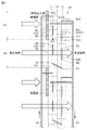
- FIG. 5 is a diagram showing the configuration of the outdoor heat exchanger of the present embodiment using a non-azeotropic refrigerant and the frost formation area.
- FIG. 6 is a front view of the outdoor heat exchanger shown in FIG.
- the isothermal line has a slope in the two-phase region. Even if the temperature is 5°C, the temperature of the refrigerant outlet can be set to 0.5°C. This means that the temperature of a portion of the outdoor heat exchanger 40 can be raised to 0° C. or higher.
- the refrigeration cycle apparatus is operated so as to obtain a temperature distribution as shown in FIG.
- refrigerant flows into the outdoor heat exchanger 40 from the pipe 54 and flows out from the outdoor heat exchanger 40 to the pipe 55 .
- the outdoor heat exchanger 40 has the first row of fins L1 arranged on the front and the second row of fins L2 arranged on the back.
- six pipes serving as refrigerant passages are arranged in parallel and are connected to the pipes on the side surfaces thereof. These six pipes are called heat transfer tubes R1 to R6 in order from the top in the fin group L1, and heat transfer tubes R7 to R12 in order from the bottom in the fin group L2.
- the refrigerant flows in from the right side of the heat transfer tube R1 at the top of the first row of fins L1, flows through the heat transfer tube R1 from right to left, and flows through the connection pipe C12. , the refrigerant flows from left to right in the heat transfer tube R2, and the refrigerant makes one round trip.
- the refrigerant flowing out of the heat transfer pipe R2 flows through the heat transfer pipe R3 from right to left via the connecting pipe C23. Then, the refrigerant flows through the heat transfer pipe R4 from left to right via the connection pipe C34, and the refrigerant makes another round trip.
- the refrigerant flowing out of the heat transfer pipe R4 flows through the heat transfer pipe R5 from right to left via the connecting pipe C45. Then, the refrigerant flows through the heat transfer pipe R6 from left to right via the connection pipe C56, and the refrigerant makes another round trip.
- the refrigerant similarly reciprocates three times in the horizontal direction of FIG.
- the heat transfer tubes R7 to R12 are different from the heat transfer tubes R1 to R6 in that the refrigerant flows upward from the lower stage.
- the refrigerant flowing out of the heat transfer pipe R6 flows through the heat transfer pipe R7 from right to left in FIG. 6 via the connecting pipe C67. Then, the refrigerant flows through the heat transfer pipe R8 from left to right via the connecting pipe, and the refrigerant makes another round trip.
- the refrigerant that has flowed out of the heat transfer pipe R8 passes through the connecting pipe C89 and flows through the heat transfer pipe R9 from right to left in FIG. Then, the refrigerant flows from left to right through the heat transfer tube R10 via the connecting pipe, and the refrigerant makes another round trip.
- the refrigerant flowing out of the heat transfer pipe R10 flows through the heat transfer pipe R11 from right to left in FIG. 6 via the connecting pipe C1011. Then, the refrigerant flows from left to right through the heat transfer pipe R ⁇ b>12 via the connection pipe, and the refrigerant makes another round trip and is sent to the pipe 55 .
- the frost formation area A1 where frost can form and the non-formation area where frost does not form can be divided into frost areas A2. Therefore, even if the amount of blown air decreases in the frosted area A1, the amount of blown air can be secured in the non-frosted area A2. In this way, the defrosting cycle can be extended by unevenly frosting the outdoor heat exchanger 40 .
- FIG. 7 is a diagram for explaining the difference in defrosting cycle between the study example and the refrigeration cycle apparatus of the present embodiment. Capacity J0, compressor frequency F0, and amount of frost G0 of the refrigeration cycle apparatus of the comparative example shown in FIGS. FIG. 7 shows the machine frequency F1 and the amount of frost G1.
- the compressor frequency F0 reaches the maximum frequency (upper limit frequency) at time t1 in order to ensure the necessary capacity. Therefore, as the amount of frost G0 increases from time t1 to t3, the capacity J0 drops early, and at time t3, defrosting becomes necessary and starts.
- the frost amount G1 is less than the frost amount G0, and the compressor frequency F1 reaches the upper limit at time t2 after time t1. Therefore, it is also at t4, after time t3, that the ability J1 drops to the value at which the defrosting start is required. Since the subsequent defrosting time is substantially constant in both the comparative example and the present embodiment, the defrosting cycle is longer in the present embodiment with the longer heating operation time than in the comparative example. Therefore, in the refrigeration cycle apparatus of the present embodiment, comfort on the load side is improved by extending the defrosting period, and the average COP is improved.
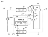
- FIG. 8 is a diagram showing the configuration of a refrigeration cycle apparatus according to Embodiment 2.
- FIG. A refrigerating cycle device 110 shown in FIG. 8 further includes a control device 90 and a temperature sensor 111 in addition to the configuration of the refrigerating cycle device 100 shown in FIG. Since other configurations have been described in FIG. 1, the description will not be repeated here.
- the control device 90 includes a CPU (Central Processing Unit) 91, a memory 92 (ROM (Read Only Memory) and RAM (Random Access Memory)), an input/output buffer (not shown), and the like.
- the CPU 91 expands the program stored in the ROM into the RAM or the like and executes it.
- the program stored in the ROM is a program in which processing procedures of the control device 90 are described.
- the control device 90 executes control of each device in the refrigeration cycle device 110 according to these programs. This control is not limited to processing by software, and processing by dedicated hardware (electronic circuit) is also possible.
- controller 90 is configured to control LEV1 according to the output of temperature sensor 111 .
- FIG. 9 is a diagram for explaining the arrangement of the temperature sensors 111.
- FIG. FIG. 9 shows how the temperature sensor 111 is arranged in the outdoor heat exchanger 40 shown in FIG. Since the outdoor heat exchanger 40 has been described with reference to FIGS. 4 to 6, the description will not be repeated here.
- the temperature sensor 111 is arranged at the boundary between the portion of the outdoor heat exchanger 40 desired to be the frosted area A1 and the portion desired to be the non-frosted area A2. If the refrigeration cycle device is controlled so that the temperature detected by the temperature sensor 111 becomes 0° C., frost forms in the frost formation area A1 and frost does not form in the non-frost formation area A2 in the heating operation at low temperature and high humidity. Therefore, the ventilation in the non-frosting area A2 can be ensured, and the defrosting period can be appropriately extended.
- the boundary between the frosted area A1 and the non-frosted area A2 can be determined experimentally in advance so as to be suitable for performing low-load heating at low temperature and low humidity.
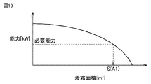
- FIG. 10 is a diagram for explaining the determination of the mounting position of the temperature sensor 111.
- FIG. As shown by the solid line in FIG. 10, the relationship between the frosting area and the capacity at the maximum frequency is obtained in advance under the operating conditions of low temperature and high humidity.
- the mounting position of the temperature sensor 111 is determined so that the area of the frosted area A1 is the frosted area S(A1) that exhibits the required performance during low-temperature and high-humidity operation.
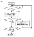
- FIG. 11 is a flowchart for explaining the processing executed by the control device in the second embodiment.
- the control device 90 determines whether or not the temperature Tsen detected by the temperature sensor 111 attached to the outdoor heat exchanger 40 is lower than the frosting temperature Tfro (step S1).
- the frosting temperature Tfro can be set at 0° C., for example.
- Tsen ⁇ Tfro does not hold (NO in S1)
- the control device 90 repeats the process of step S1. If Tsen ⁇ Tfro is established (YES in S1), the controller 90 increases the opening of LEV1 so that Tsen ⁇ Tfro (S2).
- FIG. 12 is a ph diagram for explaining changes in the refrigeration cycle in the second embodiment.
- step S2 when the opening of LEV1 is increased, the degree of supercooling at the outlet of the load-side heat exchanger decreases, and the refrigeration cycle changes from the state indicated by solid line CY1 to the state indicated by broken line CY2 on the ph diagram. .
- step S5 the controller 90 adjusts the compressor frequency F so that the heating capacity Q becomes the target heating capacity Qtar (S5), The process from step S1 is executed again.
- the controller 90 performs defrosting determination. Whether or not defrosting is necessary can be determined based on the continuous operation time of heating, the rate of decrease in capacity allowed during heating (decrease in pressure of refrigerant in low-pressure part), and the like.
- control device 90 executes the process from step S1 again. If defrosting is necessary (YES in S4), the control device 90 starts defrosting operation.
- the refrigeration cycle apparatus of Embodiment 2 increases the enthalpy at the refrigerant inlet of the outdoor heat exchanger 40 in the low-temperature and high-humidity heating operation, and uses the temperature gradient of the non-azeotropic refrigerant to increase the temperature. raise. As a result, only a part of the outdoor heat exchanger 40 is frosted, and the defrosting period is extended. In particular, since the temperature sensor 111 is arranged at the boundary between the frosted area and the non-frosted area of the outdoor heat exchanger 40, the frosted area can be accurately controlled.
- Embodiment 3. 13 is a diagram showing the configuration of a refrigeration cycle apparatus according to Embodiment 3.
- a refrigerant circuit 80 further includes an internal heat exchanger 121 and an expansion valve LEV2.
- a part of the refrigerant flowing through the pipe 53 is branched to the bypass flow path 61 , decompressed by the expansion valve LEV ⁇ b>2 , and returned to the compressor 10 .
- the refrigerant is returned to the intermediate pressure port of the compressor 10 in FIG.
- Internal heat exchanger 121 is configured to exchange heat between the refrigerant that has flowed out of indoor heat exchanger 20 and the refrigerant that has been depressurized by expansion valve LEV2 in bypass flow path 61 . Since other configurations have been described with reference to FIG. 8, the description will not be repeated here.
- FIG. 14 is a flowchart for explaining the processing executed by the control device in the third embodiment.
- the process of the flowchart of FIG. 14 includes step S12 instead of step S2 in the process of the flowchart shown in FIG. Since the processing of other parts has been described with reference to FIG. 11, step S12 will be described here.
- the opening of LEV1 is increased so that Tsen ⁇ Tfro detected by the temperature sensor 111 (S2), but in the process of FIG. YES), the opening of LEV2 is decreased so that Tsen ⁇ Tfro (S12).
- FIG. 15 is a ph diagram for explaining changes in the refrigeration cycle in the third embodiment.
- step S12 when the opening of LEV2 is decreased, the degree of supercooling at the outlet of the internal heat exchanger 121 is decreased, and the refrigerating cycle shifts from the state indicated by the solid line CY11 to the state indicated by the dashed line CY12 on the ph diagram. Change.
- the portion where the temperature sensor 111 is arranged is kept at around 0° C., and the boundary between the frosted area A1 and the non-frosted area A2 is I try to keep it as intended.
- defrosting operation is started after defrosting determination (S4).
- Embodiment 4. 16 is a diagram showing the configuration of a refrigeration cycle apparatus according to Embodiment 4.
- the refrigerant circuit 80 further includes a bypass flow path 62 and an expansion valve LEV3.
- a part of the discharged gas refrigerant flowing through the pipe 51 is branched into the bypass flow path 62 at the branch point BP2, the flow rate is adjusted by the expansion valve LEV3, and the refrigerant in the pipe 54 is joined at the junction point MP2. Since other configurations have been described with reference to FIG. 8, the description will not be repeated here.
- FIG. 17 is a flowchart for explaining the processing executed by the control device in the fourth embodiment.
- the process of the flowchart of FIG. 17 includes step S22 instead of step S2 in the process of the flowchart shown in FIG. Since the processing of other parts has been described with reference to FIG. 11, step S22 will be described here.
- the opening of LEV1 is increased so that Tsen ⁇ Tfro detected by the temperature sensor 111 (S2), but in the process of FIG. YES), the opening of LEV3 is increased so that Tsen ⁇ Tfro (S22).
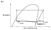
- FIG. 18 is a ph diagram for explaining changes in the refrigeration cycle in the fourth embodiment.
- step S22 when the opening of LEV3 is increased, the amount of refrigerant in the bypass flow path 62 that joins the two-phase refrigerant flowing into the outdoor heat exchanger 40 increases, and the temperature of the inlet portion of the outdoor heat exchanger 40 rises. .
- part of the discharged gas joins the refrigerant as indicated by arrows CY21 and CY22 on the ph diagram shown in FIG. do.
- the portion where the temperature sensor 111 is arranged is kept at around 0° C., and the boundary between the frosted area A1 and the non-frosted area A2 is I try to keep it as intended.
- defrosting operation is started after defrosting determination (S4).
- Embodiment 5. 19 is a diagram showing the configuration of a refrigeration cycle apparatus according to Embodiment 5.
- the heater 141 can heat the coolant flowing through the pipe 54 . Since other configurations have been described with reference to FIG. 8, the description will not be repeated here.
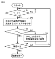
- FIG. 20 is a flowchart for explaining the processing executed by the control device in the fifth embodiment.
- the process of the flowchart of FIG. 20 includes step S32 instead of step S2 in the process of the flowchart shown in FIG. Since the processing of other parts has been described with reference to FIG. 11, step S32 will be described here.
- the opening of LEV1 is increased so that Tsen ⁇ Tfro detected by the temperature sensor 111 (S2). YES), the heating amount of the heater 141 is increased so that Tsen ⁇ Tfro (S32).
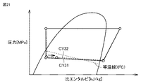
- FIG. 21 is a ph diagram for explaining changes in the refrigeration cycle in the fifth embodiment.
- step S32 when the heating amount of the heater 141 is increased, the temperature of the refrigerant flowing into the outdoor heat exchanger 40 rises, and the temperature of the inlet portion of the outdoor heat exchanger 40 rises.
- the refrigerating cycle changes from CY31 to CY32 on the ph diagram shown in FIG. 21, and the refrigerant specific enthalpy at the inlet of the outdoor heat exchanger 40 also increases as indicated by the arrows in the figure.
- the portion where the temperature sensor 111 is arranged is kept at around 0° C., and the boundary between the frosted area A1 and the non-frosted area A2 is maintained. as intended.
- defrosting operation is started after defrosting determination (S4).
- Embodiment 6. 22 is a diagram showing the configuration of a refrigeration cycle apparatus according to Embodiment 6.
- a refrigerant circuit 80 further includes a three-way valve 152 and an internal heat exchanger 151 in addition to the configuration of the refrigerating cycle device 110 in FIG.
- the three-way valve 152 is provided in the middle of the pipe 51, and in response to a control signal from the control device 90, the refrigerant discharged from the compressor 10 is directly sent to the port P1 of the four-way valve, or the internal heat exchanger 151 is It is a channel switching device that switches whether to send via.
- Internal heat exchanger 151 is configured to exchange heat between refrigerant flowing through pipe 54 and refrigerant sent from compressor 10 via three-way valve 152 . Since other configurations have been described with reference to FIG. 8, the description will not be repeated here.
- FIG. 23 is a flowchart for explaining the processing executed by the control device in the sixth embodiment.
- the process of the flowchart of FIG. 23 includes step S42 instead of step S2 in the process of the flowchart shown in FIG. Since the processing of other parts has been described with reference to FIG. 11, step S42 will be described here.
- the opening of LEV1 is increased so that Tsen ⁇ Tfro detected by the temperature sensor 111 (S2). YES), the three-way valve 152 is switched so that the refrigerant discharged from the compressor 10 flows to the internal heat exchanger 151 (S42).
- the state of the refrigerant circuit 80 becomes Tsen ⁇ Tfro, or approaches such a state.
- FIG. 24 is a ph diagram for explaining changes in the refrigeration cycle in the sixth embodiment.
- step S42 when the three-way valve 152 is switched to introduce the discharged refrigerant into the internal heat exchanger 151, the refrigerating cycle changes from CY41 to CY42 on the ph diagram shown in FIG. That is, the refrigerant discharged from compressor 10 releases heat as indicated by arrow CY42A before flowing into indoor heat exchanger 20, as indicated by CY42. Since the refrigerant that has passed through LEV1 receives this heat as indicated by arrow CY42B, the temperature of the refrigerant flowing into outdoor heat exchanger 40 rises.
- the portion where the temperature sensor 111 is arranged is kept at around 0° C.
- the boundary between A1 and the non-frosting area A2 is maintained as intended.
- defrosting operation is started after defrosting determination (S4).
- the present disclosure relates to a refrigeration cycle device 100.
- a compressor 10 In the refrigeration cycle device 100 shown in FIG. 1, a compressor 10, an indoor heat exchanger 20 (condenser), a first expansion valve LEV1, and an outdoor heat exchanger 40 (evaporator) are connected by refrigerant pipes 51 to 56.
- the non-azeotropic refrigerant passes through the outdoor heat exchanger 40 (evaporator)
- a temperature difference occurs between the inlet and outlet of the outdoor heat exchanger 40 (evaporator).
- the outdoor heat exchanger 40 (evaporator) includes fin groups L1 and L2 stacked with a gap therebetween and fin groups L1 and L2 arranged in the stacking direction of the fin groups L1 and L2. It is provided with heat transfer tubes R1 to R12 through which a non-azeotropic refrigerant flows.
- the fin groups L1 and L2 are divided into a first fin portion (frost formation area A1) to which frost may adhere in a high humidity environment and a second fin portion (non-frost formation area A2) to which frost does not adhere and ventilation is ensured.
- the refrigeration cycle device 100 further includes a control device 90 that controls the refrigerant circuit 80.
- the controller 90 controls the temperature of the non-azeotropic refrigerant flowing through the portions (heat transfer tubes R1 to R3) penetrating through the first fin portions of the heat transfer tubes to be 0° C.
- the refrigerant circuit 80 is controlled so that the temperature of the non-azeotropic refrigerant flowing through the heat transfer tubes (heat transfer tubes R4 to R12) of the fin portion is 0° C. or higher.
- the first fin portion is arranged in a predetermined frost formation area A1 in the outdoor heat exchanger 40 (evaporator).
- the second fin portion is arranged in a predetermined non-frost area A2 in the outdoor heat exchanger 40 (evaporator).
- the refrigerating cycle device 110 further includes a temperature sensor 111 arranged at the boundary between the frosted area A1 and the non-frosted area A2 in the outdoor heat exchanger 40 (evaporator).
- the control device 90 is configured to control the degree of opening of the first expansion valve LEV1 based on the output of the temperature sensor 111 so that the temperature at the boundary between the frosted area A1 and the non-frosted area A2 is 0°C. be.
- the refrigerant circuit 80 branches from the refrigerant pipe 53 connecting the indoor heat exchanger 20 (condenser) and the first expansion valve LEV1 at the branch point BP1, and the compressor 10, the second expansion valve LEV2 arranged in the bypass flow path 61, the refrigerant flowing from the indoor heat exchanger 20 (condenser) toward the branch point BP1, and the second expansion valve It further includes an internal heat exchanger 121 that exchanges heat with the refrigerant that has passed through the LEV2.
- the first fin portion is arranged in a predetermined frost formation area A1 in the outdoor heat exchanger 40 (evaporator).
- the second fin portion is arranged in a predetermined non-frost area A2 in the outdoor heat exchanger 40 (evaporator).
- the refrigerating cycle apparatus 120 shown in FIG. 13 further includes a temperature sensor 111 arranged at the boundary between the frosted area A1 and the non-frosted area A2 in the outdoor heat exchanger 40 (evaporator).
- the controller 90 adjusts the opening degree of the second expansion valve LEV2 based on the output of the temperature sensor 111, as shown in FIG. is configured to control
- the refrigerant circuit 80 branches from the refrigerant pipe between the discharge port of the compressor 10 and the indoor heat exchanger 20 (condenser), and connects the first expansion valve LEV1 and It further includes a bypass flow path 62 that merges with the refrigerant pipe connecting to the outdoor heat exchanger 40 (evaporator), and an expansion valve LEV3 arranged in the bypass flow path 62 and serving as a flow control valve.
- the first fin portion is arranged in a predetermined frost formation area A1 in the outdoor heat exchanger 40 (evaporator).
- the second fin portion is arranged in a predetermined non-frost area A2 in the outdoor heat exchanger 40 (evaporator).
- the refrigerating cycle device 130 shown in FIG. 16 further includes a temperature sensor 111 arranged at the boundary between the frosted area A1 and the non-frosted area A2 in the outdoor heat exchanger 40 (evaporator).
- the controller 90 controls the opening of the LEV3 based on the output of the temperature sensor 111, as shown in FIG. configured to
- the refrigerant circuit 80 further includes a heater 141 that heats the refrigerant flowing through the refrigerant pipe 54 connecting the first expansion valve LEV1 and the outdoor heat exchanger 40 (evaporator). Prepare.
- the first fin portion is arranged in a predetermined frost formation area A1 in the outdoor heat exchanger 40 (evaporator).
- the second fin portion is arranged in a predetermined non-frost area A2 in the outdoor heat exchanger 40 (evaporator).
- the refrigerating cycle apparatus 140 shown in FIG. 19 further includes a temperature sensor 111 arranged at the boundary between the frosted area A1 and the non-frosted area A2 in the outdoor heat exchanger 40 (evaporator).
- the controller 90 controls the heating amount of the heater 141 based on the output of the temperature sensor 111, as shown in FIG. configured as
- the refrigerant pipe 51 that is a part of the refrigerant pipe that connects the discharge port of the compressor 10 and the indoor heat exchanger 20 (condenser) is connected to the first flow path 51A.
- a second flow path 51B provided in parallel with the first flow path 51A.
- the refrigerant circuit 80 includes an internal heat exchanger 151 that exchanges heat between the refrigerant flowing from the first expansion valve LEV1 toward the outdoor heat exchanger 40 (evaporator) and the refrigerant flowing through the second flow path 51B, It further includes a three-way valve 152 that switches whether the refrigerant discharged from the compressor 10 is flowed through the first flow path 51A or the second flow path 51B.
- the first fin portion is arranged in a predetermined frost formation area A1 in the outdoor heat exchanger 40 (evaporator).
- the second fin portion is arranged in a predetermined non-frost area A2 in the outdoor heat exchanger 40 (evaporator).
- the refrigerating cycle apparatus 150 shown in FIG. 22 further includes a temperature sensor 111 arranged at the boundary between the frosted area A1 and the non-frosted area A2 in the outdoor heat exchanger 40 (evaporator).
- the control device 90 is configured to control the three-way valve 152 based on the output of the temperature sensor 111 as shown in FIG. be done.
- the refrigeration cycle device 100 further includes a four-way valve 50 that can be connected to the refrigerant circuit 80 by switching the discharge port and the suction port of the compressor 10 .
- the four-way valve 50 directs the refrigerant flowing through the refrigerant circuit 80 in the order of the compressor 10, the indoor heat exchanger 20 (condenser), the first expansion valve LEV1, and the outdoor heat exchanger 40 (evaporator). It is possible to switch between the direction and the second direction in which the air flows in the order of the compressor 10, the outdoor heat exchanger 40 (evaporator), the first expansion valve LEV1, and the indoor heat exchanger 20 (condenser).
- the defrosting cycle can be extended due to uneven frost formation, which leads to improved comfort on the load side.
- the average COP is improved by increasing the integrated heating capacity.
Landscapes
- Engineering & Computer Science (AREA)
- Mechanical Engineering (AREA)
- General Engineering & Computer Science (AREA)
- Physics & Mathematics (AREA)
- Thermal Sciences (AREA)
- Chemical & Material Sciences (AREA)
- Combustion & Propulsion (AREA)
- Air Conditioning Control Device (AREA)
- Compression-Type Refrigeration Machines With Reversible Cycles (AREA)
Priority Applications (5)
| Application Number | Priority Date | Filing Date | Title |
|---|---|---|---|
| JP2023523862A JP7599560B2 (ja) | 2021-05-27 | 2021-05-27 | 冷凍サイクル装置 |
| EP21943042.8A EP4350253A4 (en) | 2021-05-27 | 2021-05-27 | Refrigeration cycle device |
| PCT/JP2021/020183 WO2022249394A1 (ja) | 2021-05-27 | 2021-05-27 | 冷凍サイクル装置 |
| US18/558,923 US20240240845A1 (en) | 2021-05-27 | 2021-05-27 | Refrigeration cycle apparatus |
| CN202180098476.1A CN117396711A (zh) | 2021-05-27 | 2021-05-27 | 制冷循环装置 |
Applications Claiming Priority (1)
| Application Number | Priority Date | Filing Date | Title |
|---|---|---|---|
| PCT/JP2021/020183 WO2022249394A1 (ja) | 2021-05-27 | 2021-05-27 | 冷凍サイクル装置 |
Publications (1)
| Publication Number | Publication Date |
|---|---|
| WO2022249394A1 true WO2022249394A1 (ja) | 2022-12-01 |
Family
ID=84229606
Family Applications (1)
| Application Number | Title | Priority Date | Filing Date |
|---|---|---|---|
| PCT/JP2021/020183 Ceased WO2022249394A1 (ja) | 2021-05-27 | 2021-05-27 | 冷凍サイクル装置 |
Country Status (5)
| Country | Link |
|---|---|
| US (1) | US20240240845A1 (https=) |
| EP (1) | EP4350253A4 (https=) |
| JP (1) | JP7599560B2 (https=) |
| CN (1) | CN117396711A (https=) |
| WO (1) | WO2022249394A1 (https=) |
Cited By (1)
| Publication number | Priority date | Publication date | Assignee | Title |
|---|---|---|---|---|
| WO2025191651A1 (ja) * | 2024-03-11 | 2025-09-18 | 三菱電機株式会社 | 冷凍サイクル装置 |
Citations (5)
| Publication number | Priority date | Publication date | Assignee | Title |
|---|---|---|---|---|
| JPH09257334A (ja) * | 1996-03-26 | 1997-10-03 | Mitsubishi Electric Corp | ヒートポンプ式空気調和装置 |
| JP2008138921A (ja) * | 2006-11-30 | 2008-06-19 | Mitsubishi Electric Corp | 空気調和装置 |
| JP2009257741A (ja) * | 2008-03-25 | 2009-11-05 | Daikin Ind Ltd | 冷凍装置 |
| JP2015206569A (ja) * | 2014-04-23 | 2015-11-19 | 日立アプライアンス株式会社 | フィンチューブ熱交換器 |
| JP2018021721A (ja) | 2016-08-04 | 2018-02-08 | 三菱重工サーマルシステムズ株式会社 | 冷凍装置及びその制御方法 |
Family Cites Families (1)
| Publication number | Priority date | Publication date | Assignee | Title |
|---|---|---|---|---|
| KR102447943B1 (ko) * | 2018-02-05 | 2022-09-28 | 엘지전자 주식회사 | 공기조화기 |
-
2021
- 2021-05-27 CN CN202180098476.1A patent/CN117396711A/zh not_active Withdrawn
- 2021-05-27 US US18/558,923 patent/US20240240845A1/en not_active Abandoned
- 2021-05-27 JP JP2023523862A patent/JP7599560B2/ja active Active
- 2021-05-27 WO PCT/JP2021/020183 patent/WO2022249394A1/ja not_active Ceased
- 2021-05-27 EP EP21943042.8A patent/EP4350253A4/en not_active Withdrawn
Patent Citations (5)
| Publication number | Priority date | Publication date | Assignee | Title |
|---|---|---|---|---|
| JPH09257334A (ja) * | 1996-03-26 | 1997-10-03 | Mitsubishi Electric Corp | ヒートポンプ式空気調和装置 |
| JP2008138921A (ja) * | 2006-11-30 | 2008-06-19 | Mitsubishi Electric Corp | 空気調和装置 |
| JP2009257741A (ja) * | 2008-03-25 | 2009-11-05 | Daikin Ind Ltd | 冷凍装置 |
| JP2015206569A (ja) * | 2014-04-23 | 2015-11-19 | 日立アプライアンス株式会社 | フィンチューブ熱交換器 |
| JP2018021721A (ja) | 2016-08-04 | 2018-02-08 | 三菱重工サーマルシステムズ株式会社 | 冷凍装置及びその制御方法 |
Non-Patent Citations (1)
| Title |
|---|
| See also references of EP4350253A4 |
Cited By (1)
| Publication number | Priority date | Publication date | Assignee | Title |
|---|---|---|---|---|
| WO2025191651A1 (ja) * | 2024-03-11 | 2025-09-18 | 三菱電機株式会社 | 冷凍サイクル装置 |
Also Published As
| Publication number | Publication date |
|---|---|
| CN117396711A (zh) | 2024-01-12 |
| US20240240845A1 (en) | 2024-07-18 |
| EP4350253A1 (en) | 2024-04-10 |
| EP4350253A4 (en) | 2024-07-17 |
| JPWO2022249394A1 (https=) | 2022-12-01 |
| JP7599560B2 (ja) | 2024-12-13 |
Similar Documents
| Publication | Publication Date | Title |
|---|---|---|
| EP3859244B1 (en) | Air-conditioner | |
| JP2004340470A (ja) | 冷凍装置 | |
| CN112119273B (zh) | 制冷循环装置 | |
| JP2008249236A (ja) | 空気調和装置 | |
| JP2014070840A (ja) | 空気調和機 | |
| JP6004670B2 (ja) | 空気調和装置の制御装置及び空気調和装置の制御方法並びに空気調和装置のプログラム、それを備えた空気調和装置 | |
| JP6479181B2 (ja) | 空気調和装置 | |
| JP6410839B2 (ja) | 冷凍サイクル装置 | |
| JP6880204B2 (ja) | 空気調和装置 | |
| JP2017161182A (ja) | ヒートポンプ装置 | |
| JP2023503192A (ja) | 空気調和装置 | |
| WO2021014520A1 (ja) | 空気調和装置 | |
| JPWO2018055739A1 (ja) | 空気調和装置 | |
| WO2022249394A1 (ja) | 冷凍サイクル装置 | |
| JP7301173B2 (ja) | 空気調和装置 | |
| KR20190134181A (ko) | 실외 유닛 | |
| JP4966601B2 (ja) | 空気調和装置 | |
| JP7258212B2 (ja) | 空気調和装置 | |
| WO2019167249A1 (ja) | 空気調和機 | |
| CN114110738A (zh) | 空气调节机 | |
| JP7065681B2 (ja) | 空気調和装置 | |
| WO2024023991A1 (ja) | 冷凍サイクル装置 | |
| JP4649768B2 (ja) | ヒートポンプの冷却回路 | |
| JP7216258B1 (ja) | 空気調和機 | |
| JP7473857B1 (ja) | 冷凍サイクルシステム |
Legal Events
| Date | Code | Title | Description |
|---|---|---|---|
| 121 | Ep: the epo has been informed by wipo that ep was designated in this application |
Ref document number: 21943042 Country of ref document: EP Kind code of ref document: A1 |
|
| WWE | Wipo information: entry into national phase |
Ref document number: 18558923 Country of ref document: US |
|
| WWE | Wipo information: entry into national phase |
Ref document number: 2023523862 Country of ref document: JP |
|
| WWE | Wipo information: entry into national phase |
Ref document number: 202180098476.1 Country of ref document: CN |
|
| NENP | Non-entry into the national phase |
Ref country code: DE |
|
| WWE | Wipo information: entry into national phase |
Ref document number: 2021943042 Country of ref document: EP |
|
| ENP | Entry into the national phase |
Ref document number: 2021943042 Country of ref document: EP Effective date: 20240102 |