WO2022249286A1 - ファイル提供方法、スキャナ、及び、ファイル提供システム - Google Patents
ファイル提供方法、スキャナ、及び、ファイル提供システム Download PDFInfo
- Publication number
- WO2022249286A1 WO2022249286A1 PCT/JP2021/019818 JP2021019818W WO2022249286A1 WO 2022249286 A1 WO2022249286 A1 WO 2022249286A1 JP 2021019818 W JP2021019818 W JP 2021019818W WO 2022249286 A1 WO2022249286 A1 WO 2022249286A1
- Authority
- WO
- WIPO (PCT)
- Prior art keywords
- file
- scanner
- url
- data file
- data
- Prior art date
- Legal status (The legal status is an assumption and is not a legal conclusion. Google has not performed a legal analysis and makes no representation as to the accuracy of the status listed.)
- Ceased
Links
Images


Classifications
-
- H—ELECTRICITY
- H04—ELECTRIC COMMUNICATION TECHNIQUE
- H04N—PICTORIAL COMMUNICATION, e.g. TELEVISION
- H04N1/00—Scanning, transmission or reproduction of documents or the like, e.g. facsimile transmission; Details thereof
- H04N1/00795—Reading arrangements
- H04N1/00798—Circuits or arrangements for the control thereof, e.g. using a programmed control device or according to a measured quantity
- H04N1/00824—Circuits or arrangements for the control thereof, e.g. using a programmed control device or according to a measured quantity for displaying or indicating, e.g. a condition or state
-
- G—PHYSICS
- G06—COMPUTING OR CALCULATING; COUNTING
- G06F—ELECTRIC DIGITAL DATA PROCESSING
- G06F16/00—Information retrieval; Database structures therefor; File system structures therefor
- G06F16/10—File systems; File servers
- G06F16/16—File or folder operations, e.g. details of user interfaces specifically adapted to file systems
- G06F16/162—Delete operations
-
- G—PHYSICS
- G06—COMPUTING OR CALCULATING; COUNTING
- G06F—ELECTRIC DIGITAL DATA PROCESSING
- G06F16/00—Information retrieval; Database structures therefor; File system structures therefor
- G06F16/90—Details of database functions independent of the retrieved data types
- G06F16/95—Retrieval from the web
- G06F16/958—Organisation or management of web site content, e.g. publishing, maintaining pages or automatic linking
-
- H—ELECTRICITY
- H04—ELECTRIC COMMUNICATION TECHNIQUE
- H04N—PICTORIAL COMMUNICATION, e.g. TELEVISION
- H04N1/00—Scanning, transmission or reproduction of documents or the like, e.g. facsimile transmission; Details thereof
-
- H—ELECTRICITY
- H04—ELECTRIC COMMUNICATION TECHNIQUE
- H04N—PICTORIAL COMMUNICATION, e.g. TELEVISION
- H04N1/00—Scanning, transmission or reproduction of documents or the like, e.g. facsimile transmission; Details thereof
- H04N1/00127—Connection or combination of a still picture apparatus with another apparatus, e.g. for storage, processing or transmission of still picture signals or of information associated with a still picture
- H04N1/00204—Connection or combination of a still picture apparatus with another apparatus, e.g. for storage, processing or transmission of still picture signals or of information associated with a still picture with a digital computer or a digital computer system, e.g. an internet server
- H04N1/00209—Transmitting or receiving image data, e.g. facsimile data, via a computer, e.g. using e-mail, a computer network, the internet, I-fax
-
- H—ELECTRICITY
- H04—ELECTRIC COMMUNICATION TECHNIQUE
- H04N—PICTORIAL COMMUNICATION, e.g. TELEVISION
- H04N1/00—Scanning, transmission or reproduction of documents or the like, e.g. facsimile transmission; Details thereof
- H04N1/00127—Connection or combination of a still picture apparatus with another apparatus, e.g. for storage, processing or transmission of still picture signals or of information associated with a still picture
- H04N1/00204—Connection or combination of a still picture apparatus with another apparatus, e.g. for storage, processing or transmission of still picture signals or of information associated with a still picture with a digital computer or a digital computer system, e.g. an internet server
- H04N1/00244—Connection or combination of a still picture apparatus with another apparatus, e.g. for storage, processing or transmission of still picture signals or of information associated with a still picture with a digital computer or a digital computer system, e.g. an internet server with a server, e.g. an internet server
-
- H—ELECTRICITY
- H04—ELECTRIC COMMUNICATION TECHNIQUE
- H04N—PICTORIAL COMMUNICATION, e.g. TELEVISION
- H04N1/00—Scanning, transmission or reproduction of documents or the like, e.g. facsimile transmission; Details thereof
- H04N1/0035—User-machine interface; Control console
- H04N1/00405—Output means
- H04N1/00408—Display of information to the user, e.g. menus
- H04N1/00413—Display of information to the user, e.g. menus using menus, i.e. presenting the user with a plurality of selectable options
-
- H—ELECTRICITY
- H04—ELECTRIC COMMUNICATION TECHNIQUE
- H04N—PICTORIAL COMMUNICATION, e.g. TELEVISION
- H04N1/00—Scanning, transmission or reproduction of documents or the like, e.g. facsimile transmission; Details thereof
- H04N1/21—Intermediate information storage
- H04N1/2104—Intermediate information storage for one or a few pictures
Definitions
- the present invention relates to a file providing method, a scanner, and a file providing system.
- a digital copier 1 transmits image data of a read document to a web server 4, and the digital copier 1 transmits the URL of the storage destination of the transmitted image to a personal computer 3a via the Internet. , 3b in the form of e-mail, and the users of the personal computers 3a and 3b who have received the e-mail from the digital copier 1 access the URL specified by the e-mail to view the images read by the digital copier 1. Also disclosed is a network system that can be downloaded to the personal computers 3a and 3b. Further, in Patent Document 2, after the scanner 12 is caused to generate image data of a document and a password is automatically generated, only a person who knows the password can download the file of the image data using a web browser. uploading to the server device (uploading Web server 42) in a form similar to the above, and processing to send a scan mail with the specified destination address as the destination address and including the URL and password related to the upload file in the text.
- a scan mail transmission system is disclosed.
- the storage area reservation request unit 22 requests the server device 50 to secure the storage area 72 for the specific image data in response to the request for image printing, and the image code generation unit 23 A QR code Ac_QR in which a URL for accessing the storage area 72 is recorded is generated, the display control unit 24 displays the QR code Ac_QR on the display unit 40, and the specific image data acquisition unit 25 uses the access URL A printing system is disclosed in which specific image data Pdat is acquired from the server device 50, and the print control unit 26 inputs the specific image data to the printing unit 43 to print an image.
- image data is received from a terminal, identification information corresponding to the image data is generated, the identification information and the image data are associated and stored, and a two-dimensional image indicating the identification information is disclosed.
- a server device that generates a code image and transmits the two-dimensional code image to the terminal; a printing device for notifying a server device, wherein the server device transmits image data corresponding to the identification information notified from the printing device to the printing device, and the printing device receives image data from the server device.
- a print system is disclosed that performs print processing using a printer and outputs printed matter.
- the purpose is to provide a system that can appropriately share scanners with a simple procedure.
- a data file providing method comprises the step of uploading a data file generated by scanning processing by a scanner to a file relay device on the Internet; a step of the scanner displaying information indicating a URL (Uniform Resource Locator) of the temporary storage location; and returning the data file stored in the .
- URL Uniform Resource Locator
- the scanner further comprises a step of accepting an operation for permitting a reply of the data file, and in the replying step, on condition that the scanner accepts the permitting operation, the The file relay device enables the data file stored in the temporary storage location to be returned.
- the file relay device further has a step of deleting the data file from the temporary storage location after completing the return of the data file.
- the file relay device performs the temporary storage on condition that a certain period of time has passed since the data file was uploaded or the information indicating the URL became displayable by a scanner.
- the method further comprises the step of deleting the data file stored at the location.
- the scanner displays a two-dimensional code indicating the URL of the temporary storage location.
- the scanner automatically accesses a server on the Internet when an operation for starting a scanning operation is performed, and scans the server accessed by the access unit. It has a transmission unit that automatically transmits the generated data file, and a URL display unit that displays information indicating the URL received from the server.
- the transmission unit sequentially transmits the scanned data to the server when the scanning operation is started, and deletes the transmitted data when an error occurs during the scanning operation. It further has a deletion requesting unit for requesting the server.
- the access unit automatically accesses the server based on access destination information registered in advance from the factory shipment of the scanner.
- a file providing system is a file providing system including a scanner and a file relay device connected to the scanner via the Internet, wherein the scanner performs an operation for starting a scanning operation.
- an access unit that accesses the file relay device; a transmission unit that transmits a data file generated by scanning processing to the file relay device accessed by the access unit; and a storage location of the data file.
- a URL display unit for displaying information indicating a URL
- the file relay device includes: a file storage unit for storing a data file received from the transmission unit of the scanner in a predetermined storage location; and the scanner based on the URL.
- a file replying unit for replying the data file stored in the storage location in response to the web access.
- FIG. 1 is a diagram illustrating the overall configuration of a file providing system 1;
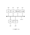
- FIG. 3 is a diagram illustrating a hardware configuration of a file providing server 2;
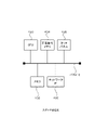
- FIG. 2 is a diagram exemplifying mainly the hardware configuration of a control portion of the scanner 4;
- 3 is a diagram illustrating a functional configuration of a file providing server 2;
- FIG. 4 is a diagram illustrating a functional configuration of a scanner 4;
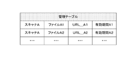
- FIG. 4 is a diagram illustrating information registered in a management database 370;
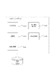
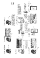
- FIG. 4 is a diagram for explaining an overview of overall operations in the file providing system 1;
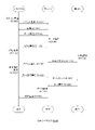
- FIG. 4 is a sequence diagram illustrating the overall operation (S10) in the file providing system 1;
- FIG. 10 is a diagram illustrating functional configurations of a server program 32 and a scanner program 52 in a modified example
- the photographed image data is often required at a later date for purposes such as resizing or additional printing, and it is necessary to store the image data in a device or a server for a certain period of time.
- the purpose of scanning is to obtain the scanned data of the document, etc., unlike the print sticker machine or the ID photo machine. consists of
- the scanner user can achieve the purpose of the scan if the scan data can be obtained immediately after scanning. Further, the user himself/herself may decide where to save the scan data after that, and the user does not continue to use the scanner after saving the scan data. Therefore, the scan data is temporarily stored in a server, etc., but after the user acquires the scan data, the server does not need to keep storing the scan data. can be deleted at any time.
- FIG. 1 is a diagram illustrating the overall configuration of a file providing system 1.
- a file providing system 1 includes a file providing server 2, a scanner 4, and a user terminal 6.
- the scanner 4 and user terminal 6 are connected to the file providing server 2 via the Internet 7. is doing.
- the file providing server 2 is a server device, stores data files received from the scanner 4 in a temporary storage location, and, in response to a request from the user terminal 6, transfers the data file stored in the temporary storage location to the user terminal 6. reply to
- the scanner 4 is an image reading device that optically reads an image from a document.
- the scanner 4 may be directly connected to the Internet 7 via WiFi, or may be connected to the Internet 7 via a computer terminal. Further, the scanner 4 may transmit the image data itself read from the document to the file providing server 2, or perform data processing such as OCR processing on the image data read from the document and provide the processing result as a file. You may transmit to the server 2.
- the user terminal 6 is, for example, a computer terminal such as a tablet terminal or a smart phone, accesses the file providing server 2 based on the URL displayed on the scanner 4, and downloads the data file from the file providing server 2.
- the file providing server 2 by providing scan data to the user terminal 6 via the file providing server 2, software and mobile applications can be downloaded, installed, read and saved in advance.
- anyone can quickly start using the scanning function of the scanner 4 without performing the previous settings.
- the file providing server 2 causes the scanner 4 to display the URL of the scan data. to allow access to the scan data.
- FIG. 2 is a diagram illustrating the hardware configuration of the file providing server 2.
- the file providing server 4 is an example of a file relay device according to the present invention.
- the file providing server 2 has a CPU 200, a memory 202, an HDD 204, a network interface 206 (network IF 206), a display device 208, and an input device 210. These components are connected via a bus 212. connected to each other.
- CPU 200 is, for example, a central processing unit.
- the memory 202 is, for example, a volatile memory and functions as a main memory.
- the HDD 204 is, for example, a hard disk drive device, and stores computer programs (eg, server program 3 in FIG.
- the network IF 206 is an interface for wired or wireless communication, and realizes connection to the Internet 7, for example.
- the display device 208 is, for example, a liquid crystal display.
- Input device 210 is, for example, a keyboard and mouse.
- FIG. 3 is a diagram exemplifying mainly the hardware configuration of the control portion of the scanner 4.
- the scanner 4 has a CPU 400 , a volatile memory 402 , a nonvolatile memory 404 , a network interface 406 (network IF 406 ), and a touch panel 408 . connected to each other.
- CPU 400 is, for example, a central processing unit.
- the memory 402 is, for example, a volatile memory and functions as a main memory.
- Non-volatile memory 404 stores computer programs (for example, scanner program 5 in FIG. 5) and other data files, for example, as a non-volatile recording device.
- a network IF 406 is an interface for wired or wireless communication.
- the touch panel 408 is, for example, a liquid crystal touch panel.
- FIG. 4 is a diagram illustrating the functional configuration of the file providing server 2.
- the server program 3 is installed and operates in the file providing server 2 of this example, and a management database 370 (management DB 370) and a file database 372 (file DB 372) are configured.
- the server program 3 is stored in a recording medium such as a CD-ROM, for example, and installed in the file providing server 2 via this recording medium.
- the server program 3 has a file storage section 300 , a URL generation section 310 , a URL notification section 320 , a file deletion section 330 , a permitted operation detection section 340 and a file reply section 350 .
- Part or all of the server program 3 may be realized by hardware such as ASIC, or may be realized by partially borrowing functions of an OS (Operating System).
- the file storage unit 300 saves the data file received from the scanner 4 in the default save location.
- the file storage unit 300 of this example stores the data file received from the scanner 4 in the storage area (temporary storage location) determined by the URL generation unit 310 in the file DB 372 .
- the URL generator 310 determines the storage location of the data file received from the scanner 4 and generates a URL for accessing the determined storage location. For example, the URL generator 310 generates a URL for accessing the data file received from the scanner 4 based on the information indicating the determined storage location and the serial number of the scanner 4 .
- the URL notification unit 320 notifies the scanner 4 of information indicating the URL generated by the URL generation unit 310 .
- the information indicating the URL may be part or all of the URL, a shortened URL, or a two-dimensional code indicating the URL.
- the file deletion unit 330 deletes the data file from the temporary storage location.
- the file deletion unit 330 stores data in the file DB 372 under the condition that a certain amount of time has passed since the data file was uploaded or the information indicating the URL became displayable by the scanner. Delete data files.
- the permission operation detection unit 340 detects that an operation has been performed on the scanner 4 to permit downloading of the data file generated by the scanning process. Based on the notification from the scanner 4, the permitted operation detection unit 340 of this example detects that an operation for permitting download has been performed.
- the file replying unit 350 replies the data file stored in the file DB 372 in response to the web access based on the URL by the user terminal 6. More specifically, the file replying unit 350 detects that there is a web access based on the URL corresponding to the data file from the user terminal 6, and that the permitting operation detecting unit 340 has performed an operation to permit the download. In this case, among the data files stored in the file DB 372, the data file corresponding to this URL is made downloadable.
- the management DB 370 stores information for managing data files (scan data) received from the scanner 4 .
- the management DB 370 associates the data file received from the scanner 4 with the identification information of the source scanner, the URL indicating the storage location of this data file, and the validity period of this URL. is stored as a management table.
- the file DB 372 stores data files received from the scanner 4 .
- FIG. 5 is a diagram illustrating the functional configuration of the scanner 4.
- the scanner program 5 is installed and operates in the scanner 4 of this example, and a setting database 570 (setting DB 570) is configured.
- the scanner program 5 of this example is pre-installed in the scanner 4, but is not limited to this. For example, it is stored in a recording medium such as a CD-ROM. 4, or stored in a specific location on the Internet and automatically downloaded and installed.
- the scanner program 5 has an access section 500 , a transmission section 510 , a deletion request section 520 , a permitted operation reception section 530 and a URL display section 540 .
- Part or all of the scanner program 5 may be realized by hardware such as ASIC, or may be realized by partially borrowing functions of an OS (Operating System).
- OS Operating System
- the access unit 500 automatically accesses the file providing server 2 on the Internet when an operation for starting the scanning operation is performed. For example, access destination information for accessing the file providing server 2 is registered in the setting DB 570 in advance, and the access unit 500 detects the access destination registered in the setting DB 570 when an operation to start a scanning operation is detected. Based on the information, the file providing server 2 is automatically accessed.
- the transmission unit 510 automatically transmits the data file generated by the scanning process to the file providing server 2 accessed by the access unit 500 . More specifically, when the scanning operation is started, the transmission unit 510 sequentially transmits the scanned data to the file providing server 2 .
- the deletion request unit 520 requests the file providing server 2 (file deletion unit 330) to delete the transmitted data when an error occurs during the scanning operation.
- the deletion requesting unit 520 of this example notifies the file providing server 2 whether or not the scanning operation has been completed normally.
- the URL display unit 540 displays information indicating the URL received from the file providing server 2.
- the URL display unit 540 of this example converts the URL received from the file providing server 2 into a two-dimensional code, and displays the converted two-dimensional code on the touch panel 408 .
- the permission operation reception unit 530 receives an operation for permitting a reply of the data file.
- Permission operation receiving unit 530 of this example causes touch panel 408 to display an operation screen for selecting whether or not to permit downloading of a data file, and receives a user's selection operation.
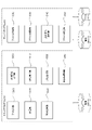
- FIG. 7 is a diagram explaining an outline of the overall operation in the file providing system 1.
- FIG. 8 is a sequence diagram explaining the overall operation (S10) in the file providing system 1.
- S10 overall operation
- FIG. 8 As shown in FIG. As an advance preparation for sharing the scanner 4, as illustrated in FIG. It is registered in the setting DB 570 in advance. In other words, the user does not need to perform any prior setting or user registration.
- step 100 when the user sets a document on the scanner 4 and taps the scan button, the scanner 4 starts scanning operation.
- the scanner 4 sends an access request to the file providing server 2 .
- the file providing server 2 responds to the access request from the scanner 4 and establishes communication.
- the scanner 4 sequentially transmits the data generated by the scanning operation to the file providing server 2.
- FIG. 108 the file providing server 2 temporarily saves the data sequentially sent from the scanner 4 in order.
- step 110 the file providing server 2 generates a URL for accessing the temporarily stored data, and notifies the scanner 4 of the generated URL.
- the scanner 4 converts the URL received from the file providing server 2 into a two-dimensional code, and displays the converted two-dimensional code.
- the user captures the two-dimensional code displayed on the scanner 4 with his or her own user terminal 6, and the user terminal 4 identifies the URL from the captured two-dimensional code.
- the user terminal 6 web-accesses the file providing server 2 based on the specified URL.
- the file providing server 2 notifies the scanner 4 of the Web access from the user terminal 6.
- the scanner 4 responds to the notification from the file providing server 2 and displays a selection screen for selecting whether or not to permit download.
- the scanner 4 accepts an operation to allow from the user on the displayed selection screen, the scanner 4 notifies the file providing server 2 that the permission operation has been performed.
- the file providing server 2 enables the data file corresponding to the URL to be downloaded, and downloads the data from the user terminal 6 in response to the request. Reply file.
- step 126 the user terminal 6 notifies the file providing server 2 to that effect when the download of the data file is normally completed.
- the file providing server 2 deletes the downloaded data file from the file DB 372 .
- step 130 the file providing server 2 notifies the scanner 4 of the completion of the download and the completion of deletion of the data file.
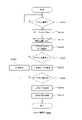
- FIG. 9 is a flowchart for explaining in more detail the processing (S20) on the scanner side in the file providing system 1.
- step 200 when the scanner 4 is powered on and the scan button is tapped (S200: Yes), the process proceeds to S205, and until the scan button is tapped. (S200: No), waits.
- the access unit 500 ( FIG. 5 ) of the scanner 4 accesses the file providing server 2 based on the access destination information registered in the setting DB 570 .
- the transmitting unit 510 sends a declaration to the file providing server 2 via the established connection to start transferring scan parameters and data. 2.
- the transmission unit 510 transmits the scan data (image data, OCR processing results, etc.) sequentially generated by the scanner 4 to the file providing server 2 .
- the deletion requesting unit 520 determines whether or not the scanning process has ended normally. The process proceeds to S245.
- the URL display unit 540 converts the URL received from the file providing server 2 into a two-dimensional code, and displays the converted two-dimensional code on the touch panel 408 .
- the scanner program 5 receives a notification from the file providing server 2 that there has been a Web access based on the URL, the process proceeds to S235, and the notification is received within a predetermined period. If not, the processing on the scanner side is terminated.
- the permitted operation receiving unit 530 displays a selection screen for selecting whether or not to permit the download on the touch panel 408, and receives the user's permitted or prohibited operation.
- the permission operation reception unit 430 notifies the file providing server 2 of the user's selection result (download permission/non-permission).
- the deletion request unit 520 requests the file providing server 2 to delete the transmitted scan data.
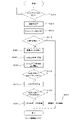
- FIG. 10 is a flow chart explaining in more detail the processing (S30) on the server side in the file providing system 1.
- the file providing server 2 (server program 3) waits until there is an access from the scanner 4 (S300: No), and when there is an access from the scanner 4, S305 (S300: Yes).
- the server program 3 (FIG. 4) responds to the access request from the scanner 4 and establishes a connection with the scanner 4.
- the server program 3 receives scan data transmitted from the scanner 4 .
- step 315 the server program 3 determines whether or not a request to delete the transmitted scan data has been received from the scanner 4 (deletion request section 520 in FIG. 5). Then, the process proceeds to S320, and when a deletion request is received, the process proceeds to S355.
- the file storage section 300 stores the scan data received from the scanner 4 in the temporary storage location determined by the URL generation section 310 in the storage area of the file DB 372 .
- the URL generation unit 310 generates a URL for accessing the scan data in the temporary storage location stored in the file storage unit 300.
- FIG. The URL notification unit 320 notifies the scanner 4 of the URL generated by the URL generation unit 310 .
- the file deletion section 330 starts monitoring the timeout period of the URL from the timing when the scanner 4 is notified of the URL. The period until timeout is the valid period in this example.
- the server program 3 determines whether or not there is web access based on the notified URL from the user terminal 6 within the validity period. The process proceeds to S340, and when there is no web access within the valid period, the process proceeds to S355.
- the permitted operation detection unit 340 notifies the scanner 4 that there has been a Web access based on the notified URL, and requests acceptance of an operation for permitting download.
- step 345 when the permitted operation detection unit 340 receives a notification from the scanner 4 (the permitted operation reception unit 530 in FIG. 5) that an operation for permitting download has been received within the validity period, The process proceeds to S350, and if the notification indicating that the download permitting operation has been accepted is not received within the validity period, the process proceeds to S355.
- the file return section 350 enables the download of scan data corresponding to the notified URL, and returns the scan data in response to a request from the user terminal 6.
- FIG. 355 the file deletion unit 330 deletes the scan data received from the scanner 4 from the file DB 372 and notifies the scanner 4 of completion of deletion. Also, the file deletion unit 330 invalidates the generated URL after the URL is generated.
- the scanner 4 can be securely shared by a simple procedure.
- information for accessing the file providing server 2 is preset in the scanner 4 , the user does not need to set the scanner 4 in advance.
- the user can obtain the image data immediately when he or she desires it.
- human error can be avoided. This reduces the possibility of unauthorized access to scan data and information security incidents.
- FIG. 11 is a diagram illustrating functional configurations of the server program 32 and the scanner program 52 in the modified example.
- the file providing server 2 determines the storage location of the scan data and generates a URL for accessing it.
- a URL for accessing this is generated on the scanner side.
- the scanner program 52 of the modified example adopts a configuration in which a URL generation unit 550 and a storage destination notification unit 560 are added to the scanner program 5 of FIG.
- the URL generation unit 550 determines the storage location of the scan data and generates a URL for accessing this storage location.
- the storage destination notification unit 560 notifies the file providing server 2 of the storage location determined by the URL generation unit 550 .
- the URL display section 540 of the modified example displays the two-dimensional code of the URL generated by the URL generation section 550 .
- the file storage unit 300 of the modified example stores the received scan data in the storage location notified by the storage destination notification unit 560 .
Landscapes
- Engineering & Computer Science (AREA)
- Multimedia (AREA)
- Signal Processing (AREA)
- General Engineering & Computer Science (AREA)
- Theoretical Computer Science (AREA)
- Human Computer Interaction (AREA)
- Databases & Information Systems (AREA)
- Physics & Mathematics (AREA)
- General Physics & Mathematics (AREA)
- Data Mining & Analysis (AREA)
- Computing Systems (AREA)
- Facsimiles In General (AREA)
- Information Transfer Between Computers (AREA)
Abstract
Description
また、特許文献2には、スキャナ12に原稿のイメージデータを生成させ、パスワードを自動生成した後、そのイメージデータのファイルを、当該パスワードを知っている者のみがWebブラウザを利用してダウンロード可能な形でサーバ装置(アップロード用Webサーバ42)にアップロードする処理を行うと共に、指定された送信先アドレスを宛先アドレスとし、アップロードファイルに関するURL及びパスワードを本文に含めたスキャンメールを送信する処理を行うスキャンメール送信システムが開示されている。
スキャナや複合機のスキャン機能を利用してスキャンデータを取得する方法としては、一旦パーソナルコンピュータのローカルストレージ、ネットワークフォルダ、又はクラウドストレージ等へスキャンデータを保存し、その後該当データを参照や複製する方法が一般的である。また、スキャン機能の利用者は、該当スキャナの所有者(或いは利用者の属する組織体が所有者)であることを前提としていることが多く、スキャン機能を利用するためには、まずドライバソフトウェアやモバイルアプリケーションのインストールと読み取り設定や保存先設定が必要となる。また、スキャナや複合機がスタンドアロンで動作可能な場合でも、同様にスキャナや複合機本体の事前設定が必要である。これらの設定はスキャナや複合機の所有者に依存しており、第三者が快適に利用することは一般的には難しい。
上記例に挙げたプリントシール機や証明写真機等では、利用者の主目的は撮影写真の取得である。撮影イメージデータは、リサイズや追加印刷等の目的で後日必要になることが多く、ある程度の期間イメージデータを機器内やサーバ等に保存しておく必要がある。一方で、スキャナの場合は、プリントシール機や証明写真機などとは異なり、原稿等のスキャンデータを取得することがスキャンを行う目的であり、プリントシール機や証明写真機などとは逆のニーズで成り立っている。スキャナの利用者はスキャン後、即座にスキャンデータを獲得できればスキャンの目的を達成できる。また、その後のスキャンデータの保存先等については利用者自身が決定すればよく、利用者はスキャンデータを保存した後は、スキャナを継続的に利用しない。よって、スキャンデータはサーバなどに一時的に保存されるが、利用者がそのスキャンデータを取得した後は、サーバはそのスキャンデータを保存し続ける必要はなく、利用者が取得して不要になったタイミングで削除できる。
上記の通りスキャナを、利用者を限定しないパブリックなものとし、利用者が望む真のニーズである「スキャン後、即座にスキャンデータを獲得する」を提唱し、この直感的なユーザーニーズを満たすことで、ユーザ体験や満足度の向上が期待できる。
図1は、ファイル提供システム1の全体構成を例示する図である。
図1に例示するように、ファイル提供システム1は、ファイル提供サーバ2と、スキャナ4と、ユーザ端末6とを含み、スキャナ4及びユーザ端末6は、インターネット7を介してファイル提供サーバ2に接続している。
ファイル提供サーバ2は、サーバ装置であり、スキャナ4から受信したデータファイルを一時保存場所に格納し、ユーザ端末6からの要求に応じて、一時保存場所に格納していたデータファイルをユーザ端末6に返信する。
スキャナ4は、原稿から光学的に画像を読み取る画像読取装置である。スキャナ4は、WiFiにより直接インターネット7に接続してもよいし、コンピュータ端末を介してインターネット7に接続してもよい。また、スキャナ4は、原稿から読み取った画像データそのものをファイル提供サーバ2に送信してもよいし、原稿から読み取った画像データに対してOCR処理等のデータ処理を行い、その処理結果をファイル提供サーバ2に送信してもよい。
ユーザ端末6は、例えば、タブレット端末やスマートフォンなどのコンピュータ端末であり、スキャナ4に表示されたURLに基づいて、ファイル提供サーバ2にアクセスし、ファイル提供サーバ2からデータファイルをダウンロードする。
図2に例示するように、ファイル提供サーバ2は、CPU200、メモリ202、HDD204、ネットワークインタフェース206(ネットワークIF206)、表示装置208、及び、入力装置210を有し、これらの構成はバス212を介して互いに接続している。
CPU200は、例えば、中央演算装置である。
メモリ202は、例えば、揮発性メモリであり、主記憶装置として機能する。
HDD204は、例えば、ハードディスクドライブ装置であり、不揮発性の記録装置としてコンピュータプログラム(例えば、図4のサーバプログラム3)やその他のデータファイルを格納する。
ネットワークIF206は、有線又は無線で通信するためのインタフェースであり、例えば、インターネット7への接続を実現する。
表示装置208は、例えば、液晶ディスプレイである。
入力装置210は、例えば、キーボード及びマウスである。
図3に例示するように、スキャナ4は、CPU400、揮発性のメモリ402、不揮発性メモリ404、ネットワークインタフェース406(ネットワークIF406)、及び、タッチパネル408を有し、これらの構成はバス412を介して互いに接続している。
CPU400は、例えば、中央演算装置である。
メモリ402は、例えば、揮発性メモリであり、主記憶装置として機能する。
不揮発性メモリ404は、例えば、不揮発性の記録装置としてコンピュータプログラム(例えば、図5のスキャナプログラム5)やその他のデータファイルを格納する。
ネットワークIF406は、有線又は無線で通信するためのインタフェースである。
タッチパネル408は、例えば、液晶タッチパネルである。
図4に例示するように、本例のファイル提供サーバ2には、サーバプログラム3がインストールされ、動作すると共に、管理データベース370(管理DB370)及びファイルデータベース372(ファイルDB372)が構成される。サーバプログラム3は、例えば、CD-ROM等の記録媒体に格納されており、この記録媒体を介して、ファイル提供サーバ2にインストールされる。
サーバプログラム3は、ファイル格納部300、URL生成部310、URL通知部320、ファイル削除部330、許可操作検知部340、及びファイル返信部350を有する。
なお、サーバプログラム3の一部又は全部は、ASICなどのハードウェアにより実現されてもよく、また、OS(Operating System)の機能を一部借用して実現されてもよい。
URL通知部320は、URL生成部310により生成されたURLを示す情報をスキャナ4に通知する。URLを示す情報とは、URLの一部又は全部であってもよいし、短縮URLでもよいし、URLを示す二次元コードであってもよい。
また、ファイル削除部330は、データファイルがアップロードされた時、又は、URLを示す情報がスキャナで表示可能になった時から、一定の時間が経過したことを条件として、ファイルDB372に保存されたデータファイルを削除する。
ファイルDB372は、スキャナ4から受信したデータファイルを格納する。
図5に例示するように、本例のスキャナ4には、スキャナプログラム5がインストールされ、動作すると共に、設定データベース570(設定DB570)が構成される。本例のスキャナプログラム5は、スキャナ4に予めインストールされているが、これに限定されるものではなく、例えば、CD-ROM等の記録媒体に格納されており、この記録媒体を介して、スキャナ4にインストールされてもよいし、インターネット上の特定の場所に保存されており、自動的にダウンロード及びインストールされてもよい。
スキャナプログラム5は、アクセス部500、送信部510、削除依頼部520、許可操作受付部530、及びURL表示部540を有する。
なお、スキャナプログラム5の一部又は全部は、ASICなどのハードウェアにより実現されてもよく、また、OS(Operating System)の機能を一部借用して実現されてもよい。
図8は、ファイル提供システム1における全体動作(S10)を説明するシーケンス図である。
スキャナ4を共用する場合の事前準備としては、図7に例示するように、購入したスキャナ4に電源を投入し、WiFi設定を行うだけで足り、ファイル提供サーバ2にアクセスするための設定情報は予め設定DB570に登録されている。つまり、ユーザは事前の設定やユーザ登録を行う必要はない。
ステップ102(S102)において、スキャナ4は、ファイル提供サーバ2にアクセス要求を送る。
ステップ104(S104)において、ファイル提供サーバ2は、スキャナ4からのアクセス要求に応じて応答し、通信を確立する。
ステップ108(S108)において、ファイル提供サーバ2は、スキャナ4から順次送られてくるデータを順に一時保存していく。
ステップ110(S110)において、ファイル提供サーバ2は、一時保存したデータにアクセスするためのURLを生成し、生成されたURLをスキャナ4に通知する。
ステップ114(S114)において、ユーザは、自身のユーザ端末6で、スキャナ4上に表示された二次元コードを撮影すると、ユーザ端末4は、撮影した二次元コードからURLを特定する。
ステップ116(S116)において、ユーザ端末6は、特定されたURLに基づいて、ファイル提供サーバ2に対してWebアクセスする。
ステップ120(S120)において、スキャナ4は、ファイル提供サーバ2からの通知に応じて、ダウンロードを許可するか否かを選択する選択画面を表示する。
ステップ122(S122)において、スキャナ4は、表示した選択画面において許可する旨の操作をユーザから受け付けると、許可操作が行われたことをファイル提供サーバ2に通知する。
ステップ124(S124)において、ファイル提供サーバ2は、許可操作が行われたことがスキャナ4から通知されると、URLに対応するデータファイルのダウンロードを可能にし、ユーザ端末6から要求に応じてデータファイルを返信する。
ステップ128(S128)において、ファイル提供サーバ2は、ダウンロードされたデータファイルをファイルDB372から削除する。
ステップ130(S130)において、ファイル提供サーバ2は、スキャナ4に対して、ダウンロードの完了及びデータファイルの削除完了を通知する。
図9に示すように、ステップ200(S200)において、スキャナ4は、電源が投入され、スキャンボタンがタップされると(S200:Yes)、S205の処理に移行し、スキャンボタンがタップされるまでは(S200:No)、待機する。
ステップ210(S210)において、アクセス部500がファイル提供サーバ2への接続を確立すると、送信部510は、確立された接続を介して、スキャンパラメータ及びデータ転送を開始する旨の宣言をファイル提供サーバ2に通知する。
ステップ220(S220)において、削除依頼部520は、スキャン処理が正常に終了したか否かを判断し、正常に終了した場合に、S225の処理に移行し、正常に終了できなかった場合に、S245の処理に移行する。
ステップ230(S230)において、スキャナプログラム5は、ファイル提供サーバ2から、上記URLに基づくWebアクセスがあった旨の通知があった場合に、S235の処理に移行し、既定の期間内に通知が無かった場合に、スキャナ側の処理を終了する。
ステップ240(S240)において、許可操作受付部430は、ユーザによる選択結果(ダウンロードの許可/不許可)をファイル提供サーバ2に通知する。
図10に示すように、ステップ300(S300)において、ファイル提供サーバ2(サーバプログラム3)は、スキャナ4からのアクセスがあるまで待機し(S300:No)、スキャナ4からアクセスがあると、S305の処理に移行する(S300:Yes)。
ステップ305(S305)において、サーバプログラム3(図4)は、スキャナ4からのアクセス要求に応じて応答し、スキャナ4との接続を確立する。
ステップ310(S310)において、サーバプログラム3は、スキャナ4から送信されてくるスキャンデータを受信する。
ステップ325(S325)において、URL生成部310は、ファイル格納部300が保存した一時保存場所のスキャンデータにアクセスするためのURLを生成する。URL通知部320は、URL生成部310により生成されたURLをスキャナ4に通知する。
ステップ335(S335)において、サーバプログラム3は、有効期間内に、ユーザ端末6から、通知したURLに基づくWebアクセスがあるか否かを判断し、有効期間内にWebアクセスがあった場合に、S340の処理に移行し、有効期間内にWebアクセスが無かった場合に、S355の処理に移行する。
ステップ345(S345)において、許可操作検知部340は、スキャナ4(図5の許可操作受付部530)から、有効期間内に、ダウンロードを許可する操作を受け付けた旨の通知を受信した場合に、S350の処理に移行し、有効期間内に、ダウンロードを許可する操作を受け付けた旨の通知を受信しなかった場合に、S355の処理に移行する。
ステップ355(S355)において、ファイル削除部330は、スキャナ4から受信したスキャンデータをファイルDB372から削除し、削除完了をスキャナ4に通知する。また、ファイル削除部330は、URL生成後である場合に、生成されたURLを無効化する。
換言すると、ユーザがスキャナ4を利用する際に、専用ソフトウェアやアプリケーションのインストール、事前設定、及びユーザ登録などが一切不要となる。また、ユーザが欲しいと思った時に、すぐにイメージデータを入手することができる。さらに、原稿のスキャン、スキャンデータの取得、及び、ファイル提供サーバ2上のスキャンデータの削除までの一連の処理を、スキャナ4の前で(その場で)完了させることで、ヒューマンエラーを原因とした、スキャンデータへの不正アクセスや情報セキュリティ事故の可能性を低減できる。
上記実施形態の変形例を説明する。
図11は、変形例におけるサーバプログラム32及びスキャナプログラム52の機能構成を例示する図である。
上記実施形態では、ファイル提供サーバ2が、スキャンデータの保存場所を決定し、これにアクセスするためのURLを生成しているが、変形例では、スキャナ4が、スキャンデータの保存場所を指定し、これにアクセスするためのURLをスキャナ側で生成する。
具体的には、図11に例示するように、変形例のスキャナプログラム52は、図5のスキャナプログラム5に、URL生成部550及び格納先通知部560を追加した構成を採る。
URL生成部550は、スキャンデータの保存場所を決定し、この保存場所にアクセスするためのURLを生成する。
格納先通知部560は、URL生成部550により決定された保存場所をファイル提供サーバ2に通知する。
変形例のURL表示部540は、URL生成部550に生成されたURLの二次元コードを表示する。
変形例のファイル格納部300は、格納先通知部560から通知された保存場所に、受信したスキャンデータを保存する。
2 ファイル提供サーバ
3 サーバプログラム
4 スキャナ
5 スキャナプログラム
6 ユーザ端末
Claims (9)
- スキャナが、スキャン処理により生成されたデータファイルを、インターネット上のファイル中継装置にアップロードするステップと、
ファイル中継装置が、アップロードされた前記データファイルを一時保存場所に保存するステップと、
前記スキャナが、前記一時保存場所のURLを示す情報を表示するステップと、
前記ファイル中継装置が、前記URLに基づくウェブアクセスに応じて、前記一時保存場所に保存しているデータファイルを返信するステップと
を有するデータファイル提供方法。 - 前記スキャナが、データファイルの返信を許可するための操作を受け付けるステップ
をさらに有し、
前記返信するステップにおいて、前記スキャナが、許可するための操作を受け付けたことを条件として、前記ファイル中継装置は、前記一時保存場所に保存しているデータファイルの返信を可能にする
請求項1に記載のデータファイル提供方法。 - 前記ファイル中継装置が、データファイルの返信を完了した後に、このデータファイルを前記一時保存場所から削除するステップ
をさらに有する請求項1又は2に記載のデータファイル提供方法。 - データファイルがアップロードされた時、又は、前記URLを示す情報がスキャナで表示可能になった時から、一定の時間が経過したことを条件として、前記ファイル中継装置が、前記一時保存場所に保存された前記データファイルを削除するステップ
をさらに有する請求項1から3のいずれか一項に記載のデータファイル提供方法。 - 前記表示するステップにおいて、前記スキャナは、前記一時保存場所のURLを示す二次元コードを表示する
請求項1から4のいずれか一項に記載のデータファイル提供方法。 - スキャン動作を開始するための操作が行われると、自動的にインターネット上のサーバにアクセスするアクセス部と、
前記アクセス部によりアクセスしたサーバに対して、スキャン処理により生成されたデータファイルを自動的に送信する送信部と、
前記サーバから受信したURLを示す情報を表示するURL表示部と
を有するスキャナ。 - 前記送信部は、前記スキャン動作が開始されると、スキャンされたデータを順次、前記サーバに送信し、
前記スキャン動作の途中にエラーが発生した場合に、送信したデータの削除を前記サーバに依頼する削除依頼部
をさらに有する請求項6に記載のスキャナ。 - 前記アクセス部は、前記スキャナの工場出荷時から予め登録されたアクセス先情報に基づいて、自動的に前記サーバにアクセスする
請求項6又は7に記載のスキャナ。 - スキャナと、このスキャナとインターネットを介して接続するファイル中継装置とを含むファイル提供システムであって、
前記スキャナは、
スキャン動作を開始するための操作が行われると、前記ファイル中継装置にアクセスするアクセス部と、
前記アクセス部によりアクセスした前記ファイル中継装置に対して、スキャン処理により生成されたデータファイルを送信する送信部と、
前記データファイルの保存場所のURLを示す情報を表示するURL表示部と
を有し、
前記ファイル中継装置は、
前記スキャナの送信部から受信したデータファイルを既定の保存場所に保存するファイル格納部と、
前記URLに基づく前記スキャナのウェブアクセスに応じて、前記保存場所に保存しているデータファイルを返信するファイル返信部と
を有する
ファイル提供システム。
Priority Applications (3)
| Application Number | Priority Date | Filing Date | Title |
|---|---|---|---|
| PCT/JP2021/019818 WO2022249286A1 (ja) | 2021-05-25 | 2021-05-25 | ファイル提供方法、スキャナ、及び、ファイル提供システム |
| US18/563,722 US20240275898A1 (en) | 2021-05-25 | 2021-05-25 | File providing method, scanner, and file providing system |
| JP2023523764A JP7577849B2 (ja) | 2021-05-25 | 2021-05-25 | ファイル提供方法、スキャナ、及び、ファイル提供システム |
Applications Claiming Priority (1)
| Application Number | Priority Date | Filing Date | Title |
|---|---|---|---|
| PCT/JP2021/019818 WO2022249286A1 (ja) | 2021-05-25 | 2021-05-25 | ファイル提供方法、スキャナ、及び、ファイル提供システム |
Publications (1)
| Publication Number | Publication Date |
|---|---|
| WO2022249286A1 true WO2022249286A1 (ja) | 2022-12-01 |
Family
ID=84229553
Family Applications (1)
| Application Number | Title | Priority Date | Filing Date |
|---|---|---|---|
| PCT/JP2021/019818 Ceased WO2022249286A1 (ja) | 2021-05-25 | 2021-05-25 | ファイル提供方法、スキャナ、及び、ファイル提供システム |
Country Status (3)
| Country | Link |
|---|---|
| US (1) | US20240275898A1 (ja) |
| JP (1) | JP7577849B2 (ja) |
| WO (1) | WO2022249286A1 (ja) |
Citations (4)
| Publication number | Priority date | Publication date | Assignee | Title |
|---|---|---|---|---|
| JP2001036701A (ja) * | 1999-07-19 | 2001-02-09 | Minolta Co Ltd | データ処理装置 |
| JP2014007483A (ja) * | 2012-06-22 | 2014-01-16 | Sharp Corp | スキャンサービスシステム、方法、およびプログラム |
| JP2018206201A (ja) * | 2017-06-07 | 2018-12-27 | シャープ株式会社 | ファイル管理装置、複合機、ファイル管理方法及びプログラム |
| JP2019053632A (ja) * | 2017-09-19 | 2019-04-04 | シャープ株式会社 | ファイル管理装置、複合機及び情報処理装置、ファイル管理方法並びにファイル管理用プログラム |
Family Cites Families (13)
| Publication number | Priority date | Publication date | Assignee | Title |
|---|---|---|---|---|
| JP4277861B2 (ja) * | 2006-02-23 | 2009-06-10 | コニカミノルタビジネステクノロジーズ株式会社 | 画像処理装置、その制御プログラム、および、その制御方法 |
| JP5713580B2 (ja) * | 2010-04-28 | 2015-05-07 | キヤノン株式会社 | 通信装置及びその制御方法、並びにプログラム |
| JP5609544B2 (ja) * | 2010-10-29 | 2014-10-22 | セイコーエプソン株式会社 | 画像入力システム、コンテンツサーバー、仲介サーバー、および、画像入力方法 |
| JP6454972B2 (ja) * | 2014-03-19 | 2019-01-23 | ブラザー工業株式会社 | 中継サーバ、および通信プログラム |
| JP6137076B2 (ja) * | 2014-07-08 | 2017-05-31 | コニカミノルタ株式会社 | 端末装置、端末装置の制御方法、および端末装置の制御プログラム |
| JP6428054B2 (ja) * | 2014-08-27 | 2018-11-28 | ブラザー工業株式会社 | 中継サーバ、および通信プログラム |
| JP6412433B2 (ja) * | 2015-01-30 | 2018-10-24 | 株式会社沖データ | メンテナンスサポートシステム、サービス提供方法及び管理装置 |
| JP6732508B2 (ja) * | 2016-04-15 | 2020-07-29 | キヤノン株式会社 | データを保存するシステム、サーバー、方法、及びプログラム |
| JP2018041171A (ja) * | 2016-09-05 | 2018-03-15 | キヤノン株式会社 | 情報処理システム、情報処理装置、画像形成装置、それらの制御方法、及びプログラム |
| JP7255237B2 (ja) * | 2019-03-04 | 2023-04-11 | コニカミノルタ株式会社 | 画像読取装置及び画像読取方法 |
| JP2021111855A (ja) * | 2020-01-08 | 2021-08-02 | 東芝テック株式会社 | 画像形成装置 |
| JP7615573B2 (ja) * | 2020-08-28 | 2025-01-17 | 富士フイルムビジネスイノベーション株式会社 | 情報処理装置、プログラム及び情報処理システム |
| JP7569183B2 (ja) * | 2020-09-08 | 2024-10-17 | キヤノン株式会社 | システム、読取装置、方法およびプログラム |
-
2021
- 2021-05-25 JP JP2023523764A patent/JP7577849B2/ja active Active
- 2021-05-25 WO PCT/JP2021/019818 patent/WO2022249286A1/ja not_active Ceased
- 2021-05-25 US US18/563,722 patent/US20240275898A1/en active Pending
Patent Citations (4)
| Publication number | Priority date | Publication date | Assignee | Title |
|---|---|---|---|---|
| JP2001036701A (ja) * | 1999-07-19 | 2001-02-09 | Minolta Co Ltd | データ処理装置 |
| JP2014007483A (ja) * | 2012-06-22 | 2014-01-16 | Sharp Corp | スキャンサービスシステム、方法、およびプログラム |
| JP2018206201A (ja) * | 2017-06-07 | 2018-12-27 | シャープ株式会社 | ファイル管理装置、複合機、ファイル管理方法及びプログラム |
| JP2019053632A (ja) * | 2017-09-19 | 2019-04-04 | シャープ株式会社 | ファイル管理装置、複合機及び情報処理装置、ファイル管理方法並びにファイル管理用プログラム |
Also Published As
| Publication number | Publication date |
|---|---|
| JP7577849B2 (ja) | 2024-11-05 |
| JPWO2022249286A1 (ja) | 2022-12-01 |
| US20240275898A1 (en) | 2024-08-15 |
Similar Documents
| Publication | Publication Date | Title |
|---|---|---|
| US8805961B2 (en) | Reading device and communication system | |
| US9053126B2 (en) | Information processing apparatus, information processing system, and recording medium | |
| US11252284B2 (en) | Image processing apparatus associating with external apparatus, control method, and storage medium | |
| US10075597B2 (en) | Image processing apparatus having file server function, and control method and storage medium therefor | |
| US20110019216A1 (en) | Network multifunctional peripheral | |
| US20080263134A1 (en) | Information-processing system, method, computer-readable medium, and computer data signal for controlling provision of information or processing service | |
| JP5262873B2 (ja) | 画像形成装置、情報処理方法、及びプログラム | |
| US20150161407A1 (en) | Information processing apparatus and information management method | |
| JP2018094870A (ja) | 情報処理システム、機器、情報処理装置、情報処理方法及びプログラム | |
| US20080222655A1 (en) | Information Processing Apparatus and Information Processing Method | |
| JP6825478B2 (ja) | 情報処理システム、情報処理装置、プログラム | |
| US11979538B2 (en) | Information processing apparatus in communication with image processing apparatus with chat service, Control method and storage medium therefor | |
| US11838250B2 (en) | Information processing method, storage medium, and chat server | |
| CN101068301B (zh) | 图像处理装置、信息管理装置、信息管理系统以及信息管理方法 | |
| US20070013942A1 (en) | Data communication system, image processing device, and method for managing data in image processing device | |
| US10958803B2 (en) | Information processing apparatus, information processing system, and non-transitory computer readable medium | |
| JP5900204B2 (ja) | 文書処理装置及びプログラム | |
| US10146488B2 (en) | Image forming apparatus, information processing method, and system | |
| JP7577849B2 (ja) | ファイル提供方法、スキャナ、及び、ファイル提供システム | |
| JP2019050530A (ja) | 画像処理装置とその処理方法及びプログラム | |
| US12379882B2 (en) | Image processing apparatus that detects error and provides uniform resource locator (URL) information to information processing apparatus to access webpage for changing settings related to the error, and non-transitory computer readable storage medium | |
| JP2019050529A (ja) | 画像処理装置とその処理方法及びプログラム | |
| US20230396723A1 (en) | File provision system, file generation apparatus, and file provision method | |
| JP4595971B2 (ja) | ネットワークスキャンシステム及び画像読取装置 | |
| JP2009033731A (ja) | 画像形成装置、文書管理方法およびプログラム |
Legal Events
| Date | Code | Title | Description |
|---|---|---|---|
| 121 | Ep: the epo has been informed by wipo that ep was designated in this application |
Ref document number: 21942941 Country of ref document: EP Kind code of ref document: A1 |
|
| ENP | Entry into the national phase |
Ref document number: 2023523764 Country of ref document: JP Kind code of ref document: A |
|
| WWE | Wipo information: entry into national phase |
Ref document number: 18563722 Country of ref document: US |
|
| NENP | Non-entry into the national phase |
Ref country code: DE |
|
| 122 | Ep: pct application non-entry in european phase |
Ref document number: 21942941 Country of ref document: EP Kind code of ref document: A1 |