WO2022244584A1 - 光ファイバケーブル - Google Patents
光ファイバケーブル Download PDFInfo
- Publication number
- WO2022244584A1 WO2022244584A1 PCT/JP2022/018319 JP2022018319W WO2022244584A1 WO 2022244584 A1 WO2022244584 A1 WO 2022244584A1 JP 2022018319 W JP2022018319 W JP 2022018319W WO 2022244584 A1 WO2022244584 A1 WO 2022244584A1
- Authority
- WO
- WIPO (PCT)
- Prior art keywords
- optical fiber
- fiber cable
- sheath
- wrap
- cable
- Prior art date
- Legal status (The legal status is an assumption and is not a legal conclusion. Google has not performed a legal analysis and makes no representation as to the accuracy of the status listed.)
- Ceased
Links
Images

Classifications
-
- G—PHYSICS
- G02—OPTICS
- G02B—OPTICAL ELEMENTS, SYSTEMS OR APPARATUS
- G02B6/00—Light guides; Structural details of arrangements comprising light guides and other optical elements, e.g. couplings
- G02B6/44—Mechanical structures for providing tensile strength and external protection for fibres, e.g. optical transmission cables
- G02B6/4401—Optical cables
- G02B6/4429—Means specially adapted for strengthening or protecting the cables
- G02B6/443—Protective covering
-
- G—PHYSICS
- G02—OPTICS
- G02B—OPTICAL ELEMENTS, SYSTEMS OR APPARATUS
- G02B6/00—Light guides; Structural details of arrangements comprising light guides and other optical elements, e.g. couplings
- G02B6/44—Mechanical structures for providing tensile strength and external protection for fibres, e.g. optical transmission cables
- G02B6/4401—Optical cables
- G02B6/4403—Optical cables with ribbon structure
-
- G—PHYSICS
- G02—OPTICS
- G02B—OPTICAL ELEMENTS, SYSTEMS OR APPARATUS
- G02B6/00—Light guides; Structural details of arrangements comprising light guides and other optical elements, e.g. couplings
- G02B6/44—Mechanical structures for providing tensile strength and external protection for fibres, e.g. optical transmission cables
- G02B6/4401—Optical cables
- G02B6/4429—Means specially adapted for strengthening or protecting the cables
- G02B6/443—Protective covering
- G02B6/4432—Protective covering with fibre reinforcements
-
- G—PHYSICS
- G02—OPTICS
- G02B—OPTICAL ELEMENTS, SYSTEMS OR APPARATUS
- G02B6/00—Light guides; Structural details of arrangements comprising light guides and other optical elements, e.g. couplings
- G02B6/44—Mechanical structures for providing tensile strength and external protection for fibres, e.g. optical transmission cables
- G02B6/4401—Optical cables
- G02B6/4429—Means specially adapted for strengthening or protecting the cables
- G02B6/4435—Corrugated mantle
-
- G—PHYSICS
- G02—OPTICS
- G02B—OPTICAL ELEMENTS, SYSTEMS OR APPARATUS
- G02B6/00—Light guides; Structural details of arrangements comprising light guides and other optical elements, e.g. couplings
- G02B6/44—Mechanical structures for providing tensile strength and external protection for fibres, e.g. optical transmission cables
- G02B6/4401—Optical cables
- G02B6/4429—Means specially adapted for strengthening or protecting the cables
- G02B6/4438—Means specially adapted for strengthening or protecting the cables for facilitating insertion by fluid drag in ducts or capillaries
-
- G—PHYSICS
- G02—OPTICS
- G02B—OPTICAL ELEMENTS, SYSTEMS OR APPARATUS
- G02B6/00—Light guides; Structural details of arrangements comprising light guides and other optical elements, e.g. couplings
- G02B6/44—Mechanical structures for providing tensile strength and external protection for fibres, e.g. optical transmission cables
- G02B6/4479—Manufacturing methods of optical cables
- G02B6/4485—Installing in protective tubing by fluid drag during manufacturing
-
- G—PHYSICS
- G02—OPTICS
- G02B—OPTICAL ELEMENTS, SYSTEMS OR APPARATUS
- G02B6/00—Light guides; Structural details of arrangements comprising light guides and other optical elements, e.g. couplings
- G02B6/44—Mechanical structures for providing tensile strength and external protection for fibres, e.g. optical transmission cables
- G02B6/4479—Manufacturing methods of optical cables
- G02B6/449—Twisting
Definitions
- the present invention relates to slotless optical fiber cables.
- Japanese Patent Application No. 2021-83719 filed in Japan on May 18, 2021 is incorporated herein by reference, and the description of this specification be part of
- a slotless optical fiber cable includes a plurality of twisted optical fibers, a pressure winding tape that covers the optical fibers, and a jacket that surrounds the pressure winding tape (for example, patent Reference 1).
- the slotless type optical fiber cable described above by reducing the mounting density of the optical fibers, it is possible to suppress the deterioration of the transmission characteristics of the optical fibers due to the contraction of the jacket at low temperatures.
- the mounting density By increasing the outer diameter of the optical fiber cable itself, the mounting density can be reduced.
- the outer diameter of the optical fiber cable is limited.
- the optical fiber when manufacturing an optical fiber cable, the optical fiber is sent out while a certain tension is applied to the optical fiber. Therefore, if the pulling force of the optical fiber in the optical fiber cable (the force required to start the relative movement of the optical fiber with respect to the optical fiber cable when the optical fiber is pulled) is weak, there is a risk of manufacturing defective products. be. Moreover, if the pulling force of the optical fiber is weak, the optical fiber may protrude from the end of the optical fiber cable during or after laying the optical fiber cable. Therefore, it is necessary to secure a pulling force equal to or greater than a predetermined value. However, when the packing density of the optical fibers in the slotless optical fiber cable is lowered, the pull-out force of the optical fibers may be lowered.
- the problem to be solved by the present invention is to provide an optical fiber cable that can reduce the mounting density while maintaining the outer diameter and drawing force.
- An optical fiber cable comprises a plurality of optical fibers, a pressure wrap that wraps the plurality of optical fibers and is in contact with the outermost optical fiber, and the pressure wrap. and a covering sheath, wherein the sheath has a plurality of recesses formed on the inner peripheral surface of the sheath and recessed radially outward of the optical fiber cable. , said recess is a fiber optic cable defining a space between said restraint and said sheath.
- the recess may include an arcuate bottom.
- the recess includes first and second side walls connected to the bottom, and the angle between the first side wall and the second side wall is 90 degrees or more. may be
- the concave portion includes first and second side walls connected to the bottom portion, and the radially inner ends of the optical fiber cables in the first and second side walls are , may each have an arc shape.
- the optical fiber cable further includes a plurality of tensile members embedded in the sheath, and the concave portions and the tensile members overlap each other in the radial direction of the optical fiber cable.
- the sheath has a convex portion formed on the outer peripheral surface of the sheath and protruding outward in the radial direction of the optical fiber cable. , the concave portion and the convex portion may overlap each other.
- the optical fiber cable may be a slotless type optical fiber cable that does not have a slotted rod.
- the pressure winding is formed by longitudinally winding the pressure winding tape around the plurality of optical fibers, and the wrap portion where the ends of the pressure winding tape overlap each other is the optical fiber. It does not have to overlap with the recess in the radial direction of the cable.
- the sheath includes a plurality of principal surfaces respectively interposed between the concave portions adjacent to each other along the circumferential direction of the optical fiber cable, and satisfies the following formula (1).
- CL 0 is the length of a virtual inscribed circle inscribed in the plurality of principal surfaces
- CL 1 is the total length of the plurality of principal surfaces. .
- a plurality of recesses that are recessed radially outward of the optical fiber cable are formed in the inner peripheral surface of the sheath, and the recesses form a space between the pressure wrap and the sheath. Therefore, it is possible to reduce the mounting density of the optical fibers while maintaining the outer diameter of the optical fiber cable and the pulling force of the optical fibers.
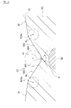
- FIG. 1 is a cross-sectional view of an optical fiber cable according to an embodiment of the invention.
- FIG. 2 is an enlarged cross-sectional view showing an inner concave portion in the embodiment of the present invention, which is an enlarged view of the II section in FIG.
- FIG. 1 is a cross-sectional view of an optical fiber cable 1 according to this embodiment.
- FIG. 2 is an enlarged cross-sectional view showing the inner concave portion in this embodiment, and is an enlarged view of the II section in FIG. 1 and 2 are cross-sectional views of the optical fiber cable 1 cut along a direction substantially orthogonal to the longitudinal direction (axial direction) of the optical fiber cable 1.
- FIG. 1 is a cross-sectional view of an optical fiber cable 1 according to this embodiment.
- FIG. 2 is an enlarged cross-sectional view showing the inner concave portion in this embodiment, and is an enlarged view of the II section in FIG. 1 and 2 are cross-sectional views of the optical fiber cable 1 cut along a direction substantially orthogonal to the longitudinal direction (axial direction) of the optical fiber cable 1.
- FIG. 1 is a cross-sectional view of an optical fiber cable 1 according to this embodiment.
- FIG. 2 is an enlarged cross-sectional view showing the inner concave portion in this embodiment, and is an enlarged view of
- the optical fiber cable 1 of this embodiment includes an optical fiber assembly 10 having a plurality of optical fibers 11, a pressure wrap 20 that wraps the optical fiber assembly 10, and a pressure wrap that covers the pressure wrap 20.
- a sheath 30 and a plurality of tensile members 60 embedded in the sheath 30 are provided.
- This optical fiber cable 1 is a so-called slotless type optical fiber cable that does not have a slotted rod. Therefore, the pressure wrap 20 enclosing the optical fiber assembly 10 is in direct contact with the optical fibers 11 positioned at the outermost periphery of the optical fiber assembly 10 .
- the optical fiber cable 1 in this embodiment is an optical fiber cable that is laid inside an already installed duct or flow path. Therefore, the outer diameter of the sheath 30 of the optical fiber cable 1 is restricted due to the restriction of the inner diameter of existing ducts.
- the use of this optical fiber cable 1 is not particularly limited to the above.
- the optical fiber assembly 10 is formed by twisting a plurality of optical fiber units, and each optical fiber unit is formed by bundling a plurality of optical fiber tape core wires.
- the optical fiber ribbon there is a so-called intermittently fixed optical fiber ribbon in which a plurality of optical fibers 11 arranged in parallel are intermittently connected by an adhesive portion.
- the plurality of optical fiber units forming the optical fiber assembly 10 are twisted together by SZ twist.
- the SZ twist is a method of twisting a plurality of filamentous bodies while reversing the twisting direction at predetermined intervals.
- the method of twisting the plurality of optical fiber units is not particularly limited to this.
- a plurality of optical fiber units forming the optical fiber aggregate 10 may be unidirectionally twisted. This unidirectional twisting is a twisting method having only one direction as a twisting direction, and is a twisting method in which a plurality of filamentous bodies are helically twisted.
- the configuration of the optical fiber unit is not particularly limited to the above configuration.
- the optical fiber unit can be configured by simply bundling a plurality of optical fibers (optical fiber strands) 11 without using an optical fiber ribbon.
- an optical fiber unit may be configured by twisting a plurality of optical fibers 11 together.
- an optical fiber unit may be configured by winding a filamentous body around a plurality of optical fibers 11 and bundling the plurality of optical fibers 11 .
- the configuration of the optical fiber assembly 10 is not particularly limited to the above.
- the optical fiber assembly 10 may be configured by simply twisting a plurality of optical fibers 11 without using optical fiber units.
- This optical fiber assembly 10 is covered with a pressing wrap 20.
- the pressing tape 20 is formed by longitudinally wrapping a pressing tape 21 around the outer circumference of the optical fiber assembly 10 .
- the pressing tape 21 has a longitudinal direction substantially aligned with the axial direction of the optical fiber cable 1 , and a width direction of the pressing tape 21 extending along the optical fiber cable 1 . is wound around the outer periphery of the optical fiber assembly 10 in a state substantially coinciding with the circumferential direction of the optical fiber assembly 10 .
- the winding method of the pressing tape 21 is not particularly limited to the above, and may be, for example, horizontal winding (spiral winding).
- both ends of the pressure winding tape 21 may not be overlapped (that is, the wrap portion 22 may not be formed), or the wrap portion 22 may not be formed.
- the wrap portion 22 may be formed by overlapping both ends of the pressing tape 21 .
- the wrap portion 22 is formed in the presser wrap 20, the smaller the width of the wrap portion 22, the more the effect of the inner concave portion 42 can be enhanced.
- both ends of the wrap portion 22 of the pressing tape 21 may be thinned so that the thickness of the wrap portion 22 is equal to or less than the thickness of the non-wrap portion.
- the wrap portion 22 When the pressure tape 21 is wound longitudinally, the wrap portion 22 should be overlapped with the main surface 41 of the inner peripheral surface 40 of the sheath 30 in the radial direction of the optical fiber cable 1, as shown in FIG. Also, the wrap portion 22 does not have to overlap the inner recess 42 of the inner peripheral surface 40 . As a result, the shape of the presser wrap 20 does not interfere with the inner concave portion 42 when the sheath 30 is contracted.
- the pressing tape 21 is made of nonwoven fabric or film.
- a specific example of the nonwoven fabric forming the pressing tape 21 is not particularly limited, but nonwoven fabrics made of fibers such as polyester, polyethylene (PE), and polypropylene (PP) can be mentioned.
- specific examples of the film constituting the pressure winding tape 21 are not particularly limited, but examples include polyethylene (PE), polypropylene (PP), polyethylene terephthalate (PET), polybutylene terephthalate (PBT), and nylon. can be mentioned.
- the pressure wrap tape 21 has such rigidity that the cross-sectional shape of the space surrounded by the pressure wrap 20 can be deformed according to the deformation of the sheath 30 and the shape change of the optical fiber assembly 10.
- the rigidity of the pressing tape 21 can be set according to the material and thickness of the pressing tape 21 . Further, the pressing tape 21 may have strength enough to protect the optical fiber 11 from the blade when the sheath 30 is torn.
- the pressing tape 20 may function as a water absorbing layer for stopping water in the optical fiber cable 1 by adding water absorbing powder to the nonwoven fabric. .
- the water absorbing powder swells and closes the gap in the optical fiber cable 1, thereby stopping the water inside the optical fiber cable 1.
- water-absorbing powders are not particularly limited, but for example, starch-based, cellulose-based, polyacrylic acid-based, polyvinyl alcohol-based, and polyoxyethylene-based materials having high absorbency, and mixtures thereof. can be mentioned.
- a method of applying the water-absorbing powder to the nonwoven fabric it may be attached (applied) to the surface of the nonwoven fabric, or may be interposed between two nonwoven fabrics.
- the sheath (outer covering) 30 is a cylindrical member that covers the outer circumference of the pressure wrap 20 .
- the optical fiber aggregate 10 wrapped in the pressure wrap 20 is housed in the inner space of this sheath 30 .
- the material forming the sheath 30 include resin materials such as polyvinyl chloride (PVC), polyethylene (PE), nylon, fluoroethylene, and polypropylene (PP).
- a plurality of (16 in this example) tensile members 60 are embedded in the sheath 30 .
- This tensile strength member 60 is a linear member for suppressing distortion and bending applied to the optical fiber 11 due to contraction of the sheath 30 .
- the plurality of tensile strength members 60 are arranged along the circumferential direction of the optical fiber cable 1 and arranged at substantially equal intervals.
- each tensile strength member 60 included in the optical fiber cable 1 is not particularly limited to the above. Also, in the present embodiment, each tensile strength member 60 is composed of a single wire rod, but the present invention is not particularly limited to this, and each tensile strength member 60 may be composed of a plurality of wire rods. Also, the tensile strength member 60 may not be embedded within the sheath 30 .
- the optical fiber assembly 10 is twisted in the SZ twist as described above, so the tensile strength member 60 also follows the twisting of the optical fiber assembly 10 and reverses its rotational direction at a predetermined cycle. while extending in the axial direction of the optical fiber cable 1 .
- the plurality of tensile members 60 extend substantially in parallel.
- the tensile member 60 follows the twisting of the optical fiber assembly 10 and spirals along the axial direction of the optical fiber cable 1. shape.
- the tensile member 60 may extend substantially parallel to the axial direction of the optical fiber cable 1 without following the twisting of the optical fiber assembly 10 .
- a non-metallic material or a metallic material can be exemplified as the material constituting the tensile strength member 60 .
- specific examples of non-metallic materials are not particularly limited, but for example, glass fiber reinforced plastic (GFRP), aramid fiber reinforced plastic (KFRP) reinforced with Kevlar (registered trademark), polyethylene fiber reinforced plastic reinforced with polyethylene fiber, etc. of fiber reinforced plastics (FRP) can be mentioned.
- GFRP glass fiber reinforced plastic
- KFRP aramid fiber reinforced plastic
- Kevlar registered trademark
- polyethylene fiber reinforced plastic reinforced with polyethylene fiber etc.
- a specific example of the metallic material is, but not limited to, a metal wire such as a copper wire.
- the sheath 30 in this embodiment has a plurality of inner concave portions 42 formed on the inner peripheral surface 40 of the sheath 30 and a plurality of outer convex portions 51 formed on the outer peripheral surface 50 of the sheath 30.
- Each of the inner recesses 42 is a linear groove extending in the axial direction of the optical fiber cable 1 following the twisting of the optical fiber assembly 10 while reversing the rotational direction at predetermined intervals.
- each of the outer convex portions 51 also follows the twisting of the optical fiber assembly 10, and is a linear shape extending so as to advance in the axial direction of the optical fiber cable 1 while reversing the rotational direction at predetermined intervals. It is a protrusion.
- the inner concave portion 42 and the outer convex portion 51 follow the twisting of the optical fiber assembly 10, and the axis of the optical fiber cable 1 is twisted. It extends spirally along the direction.
- the inner concave portion 42 may extend substantially parallel to the axial direction of the optical fiber cable 1 without following the twisting of the optical fiber assembly 10 . However, by extending following the twisting of the optical fiber assembly 10, the pressure wrap 20 and the optical fiber 11 can easily enter the space 45 formed by the inner recess 42 when the sheath 30 is contracted.
- a plurality of inner recesses 42 are formed on the inner peripheral surface 40 of the sheath 30 and arranged at substantially equal intervals along the circumferential direction of the sheath 30 .
- Each inner recess 42 is recessed radially outward of the optical fiber cable 1 .
- the radially outer side of the optical fiber cable 1 is the direction from the center of the optical fiber cable 1 to the outer side of the sheath 30 .
- the main surface 41 of the inner peripheral surface 40 is interposed between the inner recesses 42 adjacent to each other along the circumferential direction of the optical fiber cable 1 .
- the main surfaces 41 each have a gentle arc shape, and a plurality of main surfaces 41 are arranged in the circumferential direction to form a circumference concentric with the optical fiber cable 1 .
- An imaginary inscribed circle 43 that inscribes all the main surfaces 41 defines the outer periphery of the pressure wrap 20 that wraps the optical fiber assembly 10 . Therefore, a space 45 is formed between the presser wrap 20 and the sheath 30 by the inner recess 42 .
- the space 45 of the inner concave portion 42 that can be effectively used when the sheath 30 shrinks is reduced by the thickness of the pressure wrap tape 21
- the amount of shrinkage of the sheath 30 and the thickness of the pressure wrap 20 are considered.
- the cross-sectional area, width, depth, etc. of the recess 42 may be designed.
- the width of each main surface 41 on the inner peripheral surface 40 of the sheath 30 and the ratio and number of the main surfaces 41 on the inner peripheral surface 40 can be set to such an extent that the pressure wrap 20 can maintain the inscribed circle 43. preferable.
- the inscribed circle 43 is shown separated from the main surface 41 of the inner peripheral surface 40 for convenience, but the inscribed circle 43 actually coincides with the main surface 41 .
- the inscribed circle 43 is shown separated from the presser wrap 20 for convenience, but the inscribed circle 43 is actually in contact with the outer peripheral surface of the presser wrap 20 .
- each of the inner recesses 42 has a substantially triangular cross-sectional shape with an arc-shaped vertex facing radially outward of the optical fiber cable 1 .
- this inner recess 42 has a bottom 421 and a pair of side walls 422 and 423 .
- the bottom portion 421 has an arc shape.
- the arc-shaped curvature R 1 of the bottom portion 421 is preferably 0.1 mm or more (R 1 ⁇ 0.1 mm). As a result, it is possible to suppress the occurrence of cracks in the bottom portion 421 of the inner recess portion 42 due to stress concentration, compared to the case where the bottom portion of the inner recess portion has an angular apex.
- the arc-shaped curvature R 1 of the bottom portion 421 is preferably 1.0 mm or less (R 1 ⁇ 1.0 mm). do not become.
- First and second side walls 422 and 423 are connected to both ends of the bottom portion 421 .
- the first and second side walls 422 and 423 are inclined with respect to the radial direction of the optical fiber cable 1 .
- the first and second side walls 422 and 423 are inclined away from each other as they go radially inward of the optical fiber cable 1 .
- the angle ⁇ formed between the first side wall 422 and the second side wall 423 is preferably 90 degrees or more ( ⁇ 90 degrees).
- the occurrence of cracks in the bottom portion 421 of 32 can be further suppressed.
- the angle ⁇ between the first and second side walls 422 and 423 is preferably 150 degrees or less ( ⁇ 150 degrees).
- the main surface 41 of the thickness can be secured.
- the side portions 422 and 423 have a linear shape, and the cross-sectional shape of the inner recessed portion 42 is substantially triangular, but the shape is not particularly limited to this.
- the side portions 422 and 423 may have a curved shape, and the cross-sectional shape of the inner recess 42 may be substantially convex curved shape toward the radially outer side of the optical fiber cable 1.
- the inner recess 42 including the main surface 41 of the inner peripheral surface 40 of the sheath 30, may have a substantially sine curve shape.
- the angle ⁇ is the angle formed by the tangent lines of the side portions 422 and 423 , and the tangent lines of the side portions 422 and 423 at the midpoints in the depth direction from the main surface 41 . 423 tangent.
- the opening 424 of the inner recess 42 is defined by the radially inner end 422a of the optical fiber cable 1 on the first side wall 422 and the radially inner end 423a of the optical fiber cable 1 on the second side wall 423. stipulated.
- the ends 422a, 423a of the first and second side walls 422, 423 also have an arc shape.
- the arc-shaped curvature R 2 of the ends 422a and 423a is preferably 0.1 mm or more (R 2 ⁇ 0.1 mm) and preferably 5.0 mm or less (R 2 ⁇ 5.0 mm). ).
- the ends 422a and 423a of the first and second side walls 422 and 423 contact each other when the sheath 30 contracts.
- the contact can suppress concentration of stress on the optical fiber 11 .
- the plurality of outer protrusions 51 are formed on the outer peripheral surface 50 of the sheath 30 and arranged at substantially equal intervals along the circumferential direction of the sheath 30. .
- Each outer convex portion 51 protrudes radially outward of the optical fiber cable 1 .
- outer concave portions 52 are complementarily formed between the outer convex portions 51 adjacent to each other along the circumferential direction of the optical fiber cable 1 .
- Each of the outer recesses 52 is relatively recessed radially inward of the optical fiber cable 1 compared to the outer protrusions 51 .
- Each of the outer protrusions 51 has a tip directed outward in the radial direction of the optical fiber cable 1, and the tip has an arc shape.
- the sheath 30 having such a plurality of outer protrusions 51 can reduce the friction generated between the sheath 30 and the inner wall surface of the duct when the optical fiber cable 1 is installed in the existing duct. It should be noted that the outer convex portion 51 may not be formed on the sheath 30 when such an effect of reducing friction is not required.
- the sheath 30 in this embodiment has the same number of inner recesses 42 as the number of tensile members 60 (16 in this example). As shown in FIG. 1 , the plurality of inner recesses 42 are arranged so as to overlap the tensile members 60 in the radial direction of the optical fiber cable 1 . It is located radially outside the cable 1 . As a result, when stress concentrates on the inner recess 42 and a crack progresses, the crack progress can be stopped by the tensile strength member 60 located radially outside the inner recess 42 . Although not particularly limited, it is preferable that the center of the inner concave portion 42 and the center of the tensile strength member 60 substantially match in the radial direction of the optical fiber cable 1 .
- the sheath 30 has the same number of outer projections 51 as the number of tensile members 60 (16 in this example).
- the plurality of outer protrusions 51 are arranged so as to overlap the tensile member 60 in the radial direction of the optical fiber cable 1 . located outside. That is, in this embodiment, the inner concave portion 42 , the tensile strength member 60 , and the outer convex portion 51 overlap each other along the radial direction of the optical fiber cable 1 .
- a plurality of inner recesses 42 that are recessed radially outward of the optical fiber cable 1 are formed in the inner peripheral surface 40 of the sheath 30 , and the inner recesses 42 form the pressure winding 20 .
- a space 45 is formed between it and the sheath 30 . Accordingly, in the present embodiment, the inner area of the sheath 30 can be increased while maintaining the outer diameter of the optical fiber cable 1, so that the packaging density of the optical fibers 11 can be reduced.
- the pressure wrap 20 and the optical fiber 11 can enter the space 45 formed by the inner recess 42 . Therefore, application of stress to the optical fiber 11 due to contraction of the sheath 30 can be suppressed, and deterioration of the transmission characteristics of the optical fiber 11 at low temperatures can be suppressed.
- the pressure wrap 20 wrapping the optical fiber assembly 10 is pressed by the main surface (contact surface) 41 of the inner peripheral surface 40 of the sheath 30, and the outer circumference of the pressure wrap 20
- the inscribed circle 43 has the same inner diameter as the sheath without the recess 42 . For this reason, even if the inner area of the sheath 30 is increased and the mounting density of the optical fibers 11 is reduced, the pulling force of the optical fibers can be maintained.
- Example 1 is an optical fiber cable having the structure shown in FIG. is 89.0 mm2 .
- Comparative Example 1 has the same configuration as Example 1 except that (1) the sheath does not have an inner recess, and the inner area of the sheath is 87.3 mm 2 .
- Comparative Example 2 has the following points: (1) the sheath does not have an inner recess, and (2) the inner area of the sheath is substantially the same as the inner area of the sheath including the inner recess in the example. It has the same configuration as in Example 1, except that the inner area of the sheath is 88.9 mm 2 .
- Example and Comparative Example 1 had a sufficient pull-out force, and the optical fiber did not come off.
- Comparative Example 2 since it did not have an inner concave portion and the mounting density was low, it did not have a sufficient pull-out force, and the optical fiber was pulled out as soon as it started to be pulled.
- the maximum loss variation in this transmission loss evaluation was 0.15 dB/km or less.
- Comparative Example 1 since the inner area of the sheath was small, the maximum loss variation in this transmission loss evaluation exceeded 0.15 dB/km.
- the mounting density of the optical fibers 11 can be increased while maintaining the outer diameter of the optical fiber cable 1 and the pulling force of the optical fibers 11. can be reduced.
- the volume of the sheath 30 is increased by an amount corresponding to the inner recesses 42 compared to a sheath that does not have the inner recesses 42. decreases. Therefore, the amount of shrinkage of the sheath 30 itself at low temperatures is also reduced.
- the sheath and the tensile strength member are cut after cutting the sheath, thereby cutting off the optical fiber.
- the lead-out process is performed, it is difficult to cut the inner portion of the tensile strength member in the sheath, and the workability of the lead-out process is low.
- the sheath 30 inside the tensile strength member 60 is thinned by the inner concave portion 42, the sheath 30 can be easily cut off and the workability of the lead extraction process can be improved.
Landscapes
- Physics & Mathematics (AREA)
- General Physics & Mathematics (AREA)
- Optics & Photonics (AREA)
- Light Guides In General And Applications Therefor (AREA)
- Insulated Conductors (AREA)
- Communication Cables (AREA)
- Glass Compositions (AREA)
- Optical Fibers, Optical Fiber Cores, And Optical Fiber Bundles (AREA)
Priority Applications (6)
| Application Number | Priority Date | Filing Date | Title |
|---|---|---|---|
| CN202280027376.4A CN117120904A (zh) | 2021-05-18 | 2022-04-20 | 光纤电缆 |
| JP2023522575A JP7609982B2 (ja) | 2021-05-18 | 2022-04-20 | 光ファイバケーブル |
| US18/560,427 US20240248270A1 (en) | 2021-05-18 | 2022-04-20 | Optical fiber cable |
| EP22804498.8A EP4343399A4 (en) | 2021-05-18 | 2022-04-20 | Optical fiber cable |
| AU2022276271A AU2022276271B2 (en) | 2021-05-18 | 2022-04-20 | Optical fiber cable |
| CA3217545A CA3217545A1 (en) | 2021-05-18 | 2022-04-20 | Optical fiber cable |
Applications Claiming Priority (2)
| Application Number | Priority Date | Filing Date | Title |
|---|---|---|---|
| JP2021-083719 | 2021-05-18 | ||
| JP2021083719 | 2021-05-18 |
Publications (1)
| Publication Number | Publication Date |
|---|---|
| WO2022244584A1 true WO2022244584A1 (ja) | 2022-11-24 |
Family
ID=84141274
Family Applications (1)
| Application Number | Title | Priority Date | Filing Date |
|---|---|---|---|
| PCT/JP2022/018319 Ceased WO2022244584A1 (ja) | 2021-05-18 | 2022-04-20 | 光ファイバケーブル |
Country Status (7)
| Country | Link |
|---|---|
| US (1) | US20240248270A1 (https=) |
| EP (1) | EP4343399A4 (https=) |
| JP (1) | JP7609982B2 (https=) |
| CN (1) | CN117120904A (https=) |
| AU (1) | AU2022276271B2 (https=) |
| CA (1) | CA3217545A1 (https=) |
| WO (1) | WO2022244584A1 (https=) |
Cited By (1)
| Publication number | Priority date | Publication date | Assignee | Title |
|---|---|---|---|---|
| JP2024086151A (ja) * | 2022-12-16 | 2024-06-27 | 住友電気工業株式会社 | 光ファイバケーブル |
Citations (6)
| Publication number | Priority date | Publication date | Assignee | Title |
|---|---|---|---|---|
| JP2001228373A (ja) * | 2000-02-15 | 2001-08-24 | Furukawa Electric Co Ltd:The | 光ファイバケーブル |
| WO2003085436A1 (fr) * | 2002-04-08 | 2003-10-16 | Fujikura Ltd. | Cable a fibres optiques et son procede de fabrication |
| JP2018112604A (ja) * | 2017-01-10 | 2018-07-19 | 株式会社フジクラ | 光ケーブル、及び、光ケーブルの製造方法 |
| WO2020095958A1 (ja) * | 2018-11-06 | 2020-05-14 | 住友電気工業株式会社 | 光ファイバケーブル |
| CN111239942A (zh) * | 2020-02-13 | 2020-06-05 | 杭州富通通信技术股份有限公司 | 一种光缆 |
| JP2021083719A (ja) | 2019-11-28 | 2021-06-03 | 株式会社三共 | 遊技機 |
Family Cites Families (17)
| Publication number | Priority date | Publication date | Assignee | Title |
|---|---|---|---|---|
| JPH09218327A (ja) * | 1996-02-14 | 1997-08-19 | Asahi Chem Ind Co Ltd | プラスチック光ファイバケーブル |
| US6259844B1 (en) * | 1997-12-15 | 2001-07-10 | Siecor Operations, Llc | Strengthened fiber optic cable |
| US7214880B2 (en) * | 2002-09-24 | 2007-05-08 | Adc Incorporated | Communication wire |
| JP2006171570A (ja) * | 2004-12-17 | 2006-06-29 | Sumitomo Electric Ind Ltd | 光ファイバケーブル |
| JP5598853B2 (ja) * | 2010-11-17 | 2014-10-01 | 古河電気工業株式会社 | 光ファイバケーブル、光ファイバケーブルの分岐方法 |
| JP2013109172A (ja) * | 2011-11-22 | 2013-06-06 | Sumitomo Electric Ind Ltd | 光ファイバユニット及び光ケーブル |
| US8620124B1 (en) * | 2012-09-26 | 2013-12-31 | Corning Cable Systems Llc | Binder film for a fiber optic cable |
| US9086556B2 (en) * | 2013-02-12 | 2015-07-21 | Nexans | Fiber optic cable with improved flexibility, low temperature and compression resistance |
| US9625670B2 (en) * | 2014-03-21 | 2017-04-18 | Verizon Patent And Licensing Inc. | Air jetted micro-cable with super low resistance and dramatically improved for air blockage |
| US10126517B2 (en) * | 2014-06-10 | 2018-11-13 | Corning Optical Communications LLC | Fiber optic cable structured to facilitate accessing an end thereof |
| CN204790122U (zh) * | 2015-07-16 | 2015-11-18 | 成都亨通兆业精密机械有限公司 | 一种军用级野战光缆 |
| JP6298503B2 (ja) * | 2016-08-04 | 2018-03-20 | 株式会社フジクラ | 光ファイバケーブル |
| WO2018092880A1 (ja) * | 2016-11-17 | 2018-05-24 | 株式会社フジクラ | 光ファイバケーブルおよび光ファイバケーブルの製造方法 |
| US10775581B2 (en) * | 2016-12-01 | 2020-09-15 | Fujikura Ltd. | Optical cable and sheath removing method |
| EP3633432B1 (en) * | 2017-06-02 | 2022-02-09 | Fujikura Ltd. | Optical fiber cable and method for manufacturing optical fiber cable |
| CN207281361U (zh) * | 2017-10-23 | 2018-04-27 | 东莞市爱博通讯科技有限公司 | 一种高抗拉耐磨野战铠装光缆 |
| JP2021056281A (ja) * | 2019-09-27 | 2021-04-08 | 住友電気工業株式会社 | 光ファイバケーブル |
-
2022
- 2022-04-20 WO PCT/JP2022/018319 patent/WO2022244584A1/ja not_active Ceased
- 2022-04-20 JP JP2023522575A patent/JP7609982B2/ja active Active
- 2022-04-20 CN CN202280027376.4A patent/CN117120904A/zh active Pending
- 2022-04-20 CA CA3217545A patent/CA3217545A1/en active Pending
- 2022-04-20 EP EP22804498.8A patent/EP4343399A4/en active Pending
- 2022-04-20 US US18/560,427 patent/US20240248270A1/en active Pending
- 2022-04-20 AU AU2022276271A patent/AU2022276271B2/en active Active
Patent Citations (6)
| Publication number | Priority date | Publication date | Assignee | Title |
|---|---|---|---|---|
| JP2001228373A (ja) * | 2000-02-15 | 2001-08-24 | Furukawa Electric Co Ltd:The | 光ファイバケーブル |
| WO2003085436A1 (fr) * | 2002-04-08 | 2003-10-16 | Fujikura Ltd. | Cable a fibres optiques et son procede de fabrication |
| JP2018112604A (ja) * | 2017-01-10 | 2018-07-19 | 株式会社フジクラ | 光ケーブル、及び、光ケーブルの製造方法 |
| WO2020095958A1 (ja) * | 2018-11-06 | 2020-05-14 | 住友電気工業株式会社 | 光ファイバケーブル |
| JP2021083719A (ja) | 2019-11-28 | 2021-06-03 | 株式会社三共 | 遊技機 |
| CN111239942A (zh) * | 2020-02-13 | 2020-06-05 | 杭州富通通信技术股份有限公司 | 一种光缆 |
Non-Patent Citations (1)
| Title |
|---|
| See also references of EP4343399A4 |
Cited By (1)
| Publication number | Priority date | Publication date | Assignee | Title |
|---|---|---|---|---|
| JP2024086151A (ja) * | 2022-12-16 | 2024-06-27 | 住友電気工業株式会社 | 光ファイバケーブル |
Also Published As
| Publication number | Publication date |
|---|---|
| JP7609982B2 (ja) | 2025-01-07 |
| CN117120904A (zh) | 2023-11-24 |
| AU2022276271B2 (en) | 2024-12-05 |
| AU2022276271A1 (en) | 2023-11-09 |
| JPWO2022244584A1 (https=) | 2022-11-24 |
| EP4343399A1 (en) | 2024-03-27 |
| EP4343399A4 (en) | 2025-04-30 |
| US20240248270A1 (en) | 2024-07-25 |
| CA3217545A1 (en) | 2022-11-24 |
Similar Documents
| Publication | Publication Date | Title |
|---|---|---|
| CN110662992B (zh) | 光纤线缆 | |
| CN105723267A (zh) | 具有加强件的光纤电缆 | |
| AU2022202391B2 (en) | Optical fiber cable | |
| JP7652192B2 (ja) | 光ファイバケーブルおよびコネクタ付きケーブル | |
| JP2022100376A (ja) | 光ファイバケーブル | |
| JPS6035705A (ja) | 光ケーブル | |
| JP7184526B2 (ja) | 光ファイバケーブル | |
| WO2022244584A1 (ja) | 光ファイバケーブル | |
| JP7068114B2 (ja) | 光ファイバケーブル | |
| JP2004287223A (ja) | 光ファイバケーブル | |
| JP7068131B2 (ja) | 光ファイバケーブル | |
| WO2025134902A1 (ja) | 光ファイバケーブル | |
| JP7716505B2 (ja) | 光ケーブル用の光ファイバ集合体及び光ケーブル | |
| JPH11305086A (ja) | 光ファイバユニットおよびこれを用いた光ファイバケーブル | |
| WO2025033318A1 (ja) | 光ファイバケーブル | |
| JP7852654B2 (ja) | 光ファイバケーブル | |
| JP2005202106A (ja) | 光ケーブル | |
| JP7246993B2 (ja) | 三心撚り電力ケーブル | |
| JP2024145068A (ja) | 光ファイバケーブル | |
| TW202601200A (zh) | 光纖電纜 |
Legal Events
| Date | Code | Title | Description |
|---|---|---|---|
| 121 | Ep: the epo has been informed by wipo that ep was designated in this application |
Ref document number: 22804498 Country of ref document: EP Kind code of ref document: A1 |
|
| WWE | Wipo information: entry into national phase |
Ref document number: 2023522575 Country of ref document: JP |
|
| WWE | Wipo information: entry into national phase |
Ref document number: 202317071515 Country of ref document: IN |
|
| WWE | Wipo information: entry into national phase |
Ref document number: AU2022276271 Country of ref document: AU Ref document number: 2022276271 Country of ref document: AU |
|
| WWE | Wipo information: entry into national phase |
Ref document number: 3217545 Country of ref document: CA |
|
| ENP | Entry into the national phase |
Ref document number: 2022276271 Country of ref document: AU Date of ref document: 20220420 Kind code of ref document: A |
|
| WWE | Wipo information: entry into national phase |
Ref document number: 18560427 Country of ref document: US |
|
| WWE | Wipo information: entry into national phase |
Ref document number: 2022804498 Country of ref document: EP |
|
| NENP | Non-entry into the national phase |
Ref country code: DE |
|
| ENP | Entry into the national phase |
Ref document number: 2022804498 Country of ref document: EP Effective date: 20231218 |