WO2022244124A1 - 空気調和機の室内機 - Google Patents
空気調和機の室内機 Download PDFInfo
- Publication number
- WO2022244124A1 WO2022244124A1 PCT/JP2021/018898 JP2021018898W WO2022244124A1 WO 2022244124 A1 WO2022244124 A1 WO 2022244124A1 JP 2021018898 W JP2021018898 W JP 2021018898W WO 2022244124 A1 WO2022244124 A1 WO 2022244124A1
- Authority
- WO
- WIPO (PCT)
- Prior art keywords
- slide member
- support member
- slide
- indoor unit
- air conditioner
- Prior art date
- Legal status (The legal status is an assumption and is not a legal conclusion. Google has not performed a legal analysis and makes no representation as to the accuracy of the status listed.)
- Ceased
Links
Images






Classifications
-
- F—MECHANICAL ENGINEERING; LIGHTING; HEATING; WEAPONS; BLASTING
- F24—HEATING; RANGES; VENTILATING
- F24F—AIR-CONDITIONING; AIR-HUMIDIFICATION; VENTILATION; USE OF AIR CURRENTS FOR SCREENING
- F24F13/00—Details common to, or for air-conditioning, air-humidification, ventilation or use of air currents for screening
- F24F13/20—Casings or covers
-
- F—MECHANICAL ENGINEERING; LIGHTING; HEATING; WEAPONS; BLASTING
- F24—HEATING; RANGES; VENTILATING
- F24F—AIR-CONDITIONING; AIR-HUMIDIFICATION; VENTILATION; USE OF AIR CURRENTS FOR SCREENING
- F24F11/00—Control or safety arrangements
- F24F11/89—Arrangement or mounting of control or safety devices
-
- F—MECHANICAL ENGINEERING; LIGHTING; HEATING; WEAPONS; BLASTING
- F24—HEATING; RANGES; VENTILATING
- F24F—AIR-CONDITIONING; AIR-HUMIDIFICATION; VENTILATION; USE OF AIR CURRENTS FOR SCREENING
- F24F13/00—Details common to, or for air-conditioning, air-humidification, ventilation or use of air currents for screening
- F24F13/02—Ducting arrangements
- F24F13/06—Outlets for directing or distributing air into rooms or spaces, e.g. ceiling air diffuser
- F24F2013/0616—Outlets that have intake openings
Definitions
- the present disclosure relates to indoor units of air conditioners.
- the indoor unit of the air conditioner described in Patent Document 1 is equipped with a lid that opens and closes a wiring part through which cables such as electric wires are passed.
- This lid has a notch and is fixed with a screw.
- a tool such as a screwdriver to loosen the screw and slide the lid.
- the present disclosure has been made to solve the problems described above, and aims to provide an indoor unit of an air conditioner that makes it easier to open and close the wire connection part.
- the indoor unit of the air conditioner according to the present disclosure is movable between a wire passing portion through which a cable is passed, a cover position covering at least part of the wire passing portion, and an open position in which the wire passing portion is opened.
- a sliding member movable in a sliding direction between a restricting position restricting the movement of the cover member and a releasing position permitting the movement of the cover member; and the sliding member at the restricting position.
- the first engaging portion is located above the slide member, the dimension of the shoulder portion in the vertical direction is La1, and the thickness of the portion of the slide member supported by the head is is Ta1 and the thickness of the first engaging portion is Tb1, La1>Ta1+Tb1 is satisfied.
- FIG. 3 is a perspective view of the indoor unit of Fig. 2 with a decorative panel removed; It is an enlarged view near the opening-and-closing mechanism in embodiment.
- 4 is an exploded view of the opening/closing mechanism in the embodiment; FIG. It is the perspective view which looked at the slide member in embodiment from the downward direction. It is the figure which looked at the slide member in embodiment from upper direction. 4 is a perspective view of the opening/closing mechanism when the cover member in the embodiment is in the cover position; FIG. FIG.
- FIG. 5 is a cross-sectional view of the opening/closing mechanism when the slide member in the embodiment is at the restricting position;
- FIG. 5 is a cross-sectional view of the opening/closing mechanism when the slide member is at the release position in the embodiment;
- FIG. 10 is a perspective view of the opening/closing mechanism when the cover member is tilted downward according to the embodiment;
- 12 is a perspective view of the opening/closing mechanism when the cover member of FIG. 11 is moved to the open position;
- FIG. 1 is a diagram showing a configuration example of an air conditioner A according to this embodiment.
- the air conditioner A includes an indoor unit 100 , an outdoor unit 200 , a gas refrigerant pipe 300 and a liquid refrigerant pipe 400 .
- the gas refrigerant pipe 300 and the liquid refrigerant pipe 400 connect the indoor unit 100 and the outdoor unit 200, respectively.
- the outdoor unit 200 has a compressor 210 , a four-way valve 220 , an outdoor heat exchanger 230 and an expansion valve 240 .
- the compressor 210 compresses and discharges the sucked refrigerant.
- Compressor 210 may be able to change the capacity of compressor 210 (the amount of refrigerant sent out per unit time) by arbitrarily changing the operating frequency using an inverter circuit or the like.
- the four-way valve 220 is a valve that switches the flow of refrigerant between cooling operation and heating operation.
- the outdoor heat exchanger 230 exchanges heat between the refrigerant and air (outdoor air). For example, during heating operation, the outdoor heat exchanger 230 functions as an evaporator to evaporate the liquid-phase refrigerant. During cooling operation, the outdoor heat exchanger 230 functions as a condenser to condense the gaseous refrigerant.
- the expansion valve 240 is flow control means capable of controlling the flow rate of refrigerant.
- the expansion valve 240 reduces the pressure of the refrigerant to expand it.
- the expansion valve 240 adjusts the degree of opening based on instructions from a control device (not shown) or the like.
- the indoor heat exchanger 110 exchanges heat between indoor air and refrigerant. During heating operation, indoor heat exchanger 110 functions as a condenser to condense the refrigerant. During cooling operation, indoor heat exchanger 110 functions as an evaporator to evaporate the refrigerant.
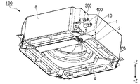
- FIG. 2 is a perspective view of the indoor unit 100 according to the embodiment with the decorative panel 50 attached
- FIG. 3 is a perspective view of the indoor unit 100 with the decorative panel 50 removed.
- the indoor unit 100 a four-direction cassette type indoor unit that blows air into the room from four outlets 52 is shown.
- the indoor unit 100 has a housing 8 that opens downward.
- the housing 8 is made of heat insulating material, for example.
- the decorative panel 50 has a square shape and covers the opening at the lower end of the housing 8 .
- the indoor unit 100 is installed on the indoor ceiling with most of the housing 8 and the like arranged behind the ceiling (above the ceiling surface) and the decorative panel 50 arranged in the indoor space.
- the decorative panel 50 has an inlet 51 and four outlets 52 .
- the suction port 51 is provided in the central portion of the decorative panel 50 and used to draw air into the indoor unit 100 .
- the four outlets 52 are arranged along each side (four sides) of the rectangular decorative panel 50 around the inlet 51 . Each air outlet 52 is used to blow temperature-controlled air into the room.
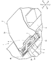
- FIG. 4 is an enlarged view of the periphery of the opening/closing mechanism 1 viewed from above.
- a wiring port 10 for inserting the cable C is provided directly below the pipe connection portion 9 of the gas refrigerant pipe 300 and the liquid refrigerant pipe 400 .
- An opening/closing mechanism 1 is provided below the wiring port 10 .
- the cable C is, for example, a power line or the like for supplying power to the indoor unit 100 .
- the cable C may be a communication line for communicating between the indoor unit 100 and the outdoor unit 200 .
- the number of cables C is one in the figure, a plurality of cables C may be bundled.
- FIG. 5 is an exploded view of the opening/closing mechanism 1 according to the embodiment.
- the opening/closing mechanism 1 is configured to be able to open/close the wiring portion 5 of the indoor unit 100 .
- the wire passing portion 5 is provided for passing a cable C extending from the inside to the outside of the indoor unit 100 .
- illustration of the wiring port 10 is omitted in FIG. 5
- the cable C is drawn out from the inside of the indoor unit 100 to the outside through the wire passing portion 5 and the wiring port 10 .
- the wire passing portion 5 in the present embodiment is a concave portion recessed upward from the lower surface of the housing 8 . Note that the wire connection portion 5 may be formed in a component of the indoor unit 100 other than the housing 8 .
- the opening/closing mechanism 1 has a cover member 2, a fixed member 3, a slide member 4, a first support member 6, and a second support member 7.
- the first support member 6 has a head 6a, a shoulder portion 6b, and a threaded portion 6c.
- the second support member 7 has a head 7a, a shoulder portion 7b, and a screw portion 7c. That is, the first support member 6 and the second support member 7 are so-called shoulder bolts.
- the first support member 6 and the second support member 7 may have the same shape, in which case the parts can be shared.
- the cover member 2 is arranged to cover the wire passing portion 5 from below.
- the cover member 2 has a cover body 2a and two locking portions 2b.
- the cover main body 2a has a plate shape extending along a plane perpendicular to the vertical direction.
- Two connection portions 2g projecting upward (+Z side) are formed at the end portion of the cover main body 2a.
- Each engaging portion 2b extends away from the cover main body 2a from the upper end portion of each connecting portion 2g. That is, each connecting portion 2g connects each engaging portion 2b to the cover main body 2a.
- the two locking portions 2b are located above the slide member 4. As shown in FIG. When the slide member 4 is supported from below by the first support member 6 and the second support member 7, the two locking portions 2b are supported by the slide member 4 from below. In other words, the two locking portions 2b are indirectly supported by the first support member 6 and the second support member 7. As shown in FIG.
- the two locking portions 2b are located above the cover main body 2a.
- a guide wall 2e is formed on each engaging portion 2b. Each guide wall 2e protrudes downward from the end of each engaging portion 2b opposite to the connecting portion 2g. Each guide wall 2e faces each connecting portion 2g.
- the two locking portions 2b one is formed with a first insertion hole 2c, and the other is formed with a second insertion hole 2d.
- the locking portion 2b formed with the first insertion hole 2c is referred to as the "first locking portion 2b1”
- the locking portion 2b formed with the second insertion hole 2d is referred to as the "second locking portion”. 2b2”.
- a guide groove 2f is formed in the guide wall 2e of the first locking portion 2b1.
- the guide groove 2f penetrates the guide wall 2e and has an elongated shape extending along the direction in which the two locking portions 2b are arranged.
- the longitudinal direction of the guide groove 2f coincides with the sliding direction of the slide member 4.
- the inner diameter of the first insertion hole 2c is represented as “inner diameter Db1”
- the inner diameter of the second insertion hole 2d is represented as “inner diameter Db2”.
- the inner diameter Db1 is larger than the inner diameter Db2.
- the fixed member 3 is fixed to the housing 8.
- the fixing member 3 is formed by processing sheet metal and is insert-molded in the housing 8 .
- the fixing member 3 may be fixed to the housing 8 by a method other than insert molding (for example, screw fixing or adhesive fixing).
- the fixing member 3 is formed with a first screw hole 3a and a second screw hole 3b.
- the first screw hole 3a is arranged at a position overlapping with the first insertion hole 2c
- the second screw hole 3b is arranged at a position overlapping with the second insertion hole 2d.
- a first support member 6 is fastened to the first screw hole 3a through a first insertion hole 2c
- a second support member 7 is fastened to the second screw hole 3b through a second insertion hole 2d.
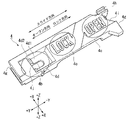
- FIG. 6 is a perspective view of the slide member 4 viewed from below
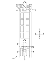
- FIG. 7 is a view of the slide member 4 viewed from above.
- the slide member 4 has a notch portion 4a through which the shoulder portion 6b of the first support member 6 is passed, and an elongated hole 4b through which the shoulder portion 7b of the second support member 7 is passed.
- the slide member 4 is slidable along the slide direction shown in FIG. In FIG. 6 and the like, the sliding direction is represented by the Y-axis.
- a direction orthogonal to both the vertical direction (Z-axis) and the sliding direction (Y-axis) is called an "orthogonal direction", and is represented by the X-axis in FIG. 6 and the like.
- the sliding direction is also the direction in which the cutouts 4a and the long holes 4b are arranged.
- the direction from the long hole 4b to the notch 4a is called the lock direction
- the direction from the notch 4a to the long hole 4b is called the open direction.
- the open direction is the +Y side
- the lock direction is the -Y side.
- a display portion for displaying the locking direction and the opening direction is provided on the lower surface of the slide member 4 . More specifically, as the display portion, characters of "OPEN" and "LOCK" are formed together with arrows indicating respective directions.
- the slide member 4 can switch between a state in which the movement of the cover member 2 is restricted and a state in which the movement of the cover member 2 is permitted by sliding relative to the fixed member 3 .
- a position of the slide member 4 in a state where the movement of the cover member 2 is restricted is called a "restricted position”.
- the position of the slide member 4 in a state in which the movement of the cover member 2 is permitted is called a "release position.”
- the slide member 4 has a first area 4c having a notch portion 4a, a second area 4d having a long hole 4b, and a transition portion 4e connecting the first area 4c and the second area 4d.
- a first regulation surface 4d1 and a second regulation surface 4d2 facing downward are provided in the second area 4d.
- the second restricting surface 4d2 is located below the first restricting surface 4d1. Further, the second restricting surface 4d2 is provided in the opening direction (+Y side) from the first restricting surface 4d1.
- the long hole 4b is formed across the first restricting surface 4d1 and the second restricting surface 4d2. In other words, the long hole 4b is formed so as to straddle the vertical step provided in the second area 4d.
- the notch 4a opens toward the -Y side (locking direction).
- a projection 4f is formed on each of the pair of side surfaces of the elongated hole 4b.
- the "side surface of the long hole 4b" is a surface extending along the sliding direction inside the long hole 4b.
- the pair of protrusions 4f are arranged at positions facing each other in the direction perpendicular to the slide direction.
- the width of the notch 4a in the orthogonal direction (X-axis) is expressed as "width W1".
- the distance between the side surfaces of the long hole 4b in the orthogonal direction is expressed as "width W2”.
- the distance between the pair of projections 4f in the orthogonal direction is expressed as "width Wt2".
- the outer diameter of the shoulder portion 7b of the second support member 7 is expressed as "outer diameter Dc2" (see FIG. 9). In this embodiment, Wt2 ⁇ Dc2 ⁇ W2.
- the pair of projections 4f may prevent the slide member 4 from unexpectedly moving (for example, due to vibration) in the sliding direction with respect to the second support member 7. It has the function of regulating movement.
- the projection 4f climbs over the second support member 7 in the sliding direction.
- the protrusion 4f and the surrounding portions are elastically deformed so as to widen the width W1 of the elongated hole 4b.
- the amount of this elastic deformation can be reduced by providing the two projections 4f so as to face each other.
- the number of projections 4f is one, it is possible to exhibit the function of restricting the sudden movement of the slide member 4.
- operation portions 4g are provided at both ends of the slide member 4 in the slide direction.
- the operation portion 4g is used when the operator moves the slide member 4 in the slide direction. For example, when moving the slide member 4 in the opening direction, the operator pushes the operating portion 4g positioned at the end in the locking direction ( ⁇ Y side). Conversely, when moving the slide member 4 in the locking direction, the operator pushes the operating portion 4g positioned at the end in the opening direction (+Y side).
- the operation portions 4g in the present embodiment are both end faces of the slide member 4 in the slide direction.
- the shape of the operation portion 4g can be changed as appropriate, and may be, for example, a projection shape or a ring shape.
- the slide member 4 can have only one operating portion 4g.
- the slide member 4 is formed with guide claws 4h.
- the guide claw 4h is L-shaped when viewed from the sliding direction.
- the guide claw 4h is inserted into the guide groove 2f of the cover member 2.
- a portion of the guide claw 4h protruding downward is engaged with the guide wall 2e from the -X side.
- the guide claws 4h and the guide grooves 2f enable the slide member 4 to move in the slide direction with respect to the cover member 2, and to rotate the cover member 2 and the slide member 4 integrally.
- FIG. 9 is a cross-sectional view of the opening/closing mechanism 1 when the slide member 4 is at the restricted position.
- the shoulder portion 6 b of the first support member 6 passes through the notch portion 4 a (see FIG. 7) of the slide member 4 and the first insertion hole 2 c of the cover member 2 .
- the screw portion 6c of the first support member 6 is fastened to the first screw hole 3a.
- the shoulder portion 7b of the second support member 7 passes through the long hole 4b of the slide member 4 and the second insertion hole 2d of the cover member 2. As shown in FIG. In this state, the screw portion 7c of the second support member 7 is fastened to the second screw hole 3b.
- the head 6a of the first support member 6 and the fixed member 3 Between the head 6a of the first support member 6 and the fixed member 3, the first engaging portion 2b1 of the cover member 2 and the slide member 4 are sandwiched.
- the second locking portion 2b2 of the cover member 2 and the slide member 4 are sandwiched between the head 7a of the second support member 7 and the fixed member 3.
- the head 7a of the second support member 7 overlaps the second regulation surface 4d2 in the vertical direction when the slide member 4 is in the regulation position (FIG. 9).
- the outer diameter Da1 of the head 6a of the first support member 6 is larger than the width W1 of the notch 4a of the slide member 4, but smaller than the inner diameter Db1 of the first insertion hole. That is, Db1>Da1>W1 is satisfied.
- the outer diameter Da2 of the head 7a of the second support member 7 is larger than the width W2 of the elongated hole 4b of the slide member 4 and larger than the inner diameter Db2 of the second insertion hole 2d of the cover member 2. As shown in FIG. That is, Da2>W2 and Da2>Db2 are satisfied.
- the length in the vertical direction of the shoulder portion 6b of the first support member 6 is expressed as "dimension La1".
- the thickness in the vertical direction of the slide member 4 at the portion sandwiched between the head 6a of the first support member 6 and the first engaging portion 2b1 is represented as "thickness Ta1". That is, the thickness Ta1 is the thickness in the vertical direction of the portion of the slide member 4 in the restricted position that is supported from below by the head 6a.
- the thickness (board thickness) of the first locking portion 2b1 in the up-down direction is expressed as "thickness Tb1".
- Dimension La1 is greater than the sum of thickness Ta1 and thickness Tb1. That is, La1>Ta1+Tb1 is satisfied. Therefore, even when the first support member 6 is fastened to the first screw hole 3a and the shoulder portion 6b is in contact with the fixed member 3, the cover member 2 and the slide member 4 are not held between the head 6a and the fixed member 3. not be compressed.
- the length in the vertical direction of the shoulder portion 7b of the second support member 7 is expressed as "dimension La2".
- the vertical thickness of the portion of the slide member 4 sandwiched between the head 7a of the second support member 7 and the second locking portion 2b2 is defined as "thickness Ta2. ”. That is, the thickness Ta2 is the thickness in the vertical direction of the portion of the slide member 4 in the restricted position that is supported from below by the head 7a.
- the vertical thickness (plate thickness) of the second locking portion 2b2 is expressed as "thickness Tb2".
- Dimension La2 is greater than the sum of thickness Ta2 and thickness Tb2. That is, La2>Ta2+Tb2 is satisfied. Therefore, even when the second support member 7 is fastened to the second screw hole 3b and the shoulder portion 7b is in contact with the fixed member 3, the cover member 2 and the slide member 4 are not held between the head 7a and the fixed member 3. not be compressed.
- the value of La2-(Ta2+Tb2) and La1-(Ta1+Tb1)) be 1 mm or less.
- the projection 4f (see FIG. 7) is located in the lock direction (-Y side) relative to the shoulder portion 7b of the second support member 7. As shown in FIG. As described above, this embodiment satisfies Wt2 ⁇ Dc2 ⁇ W2.
- the protrusion 4f rides over the shoulder portion 7b of the second support member 7 in the opening direction (+Y side). As a result, the slide member 4 moves to the release position.
- the protrusion 4f is positioned in the opening direction from the center of the shoulder portion 7b of the second support member 7.
- the opening of the notch 4a passes through the shoulder 6b of the first support member 6 in the opening direction. As a result, the notch 4 a is separated from the first support member 6 .
- FIG. 10 is a cross-sectional view when the slide member 4 is moved to the release position in the slide direction and further shifted downward.
- the shoulder portion 7b of the second support member 7 is separated from the second restricting surface 4d2 in the locking direction (-Y side).
- the vertical thickness of the portion of the slide member 4 sandwiched between the head 7a of the second support member 7 and the second locking portion 2b2 is referred to as "thickness Tc2". show.
- the thickness Tc2 is the plate thickness of the slide member 4 at the portion where the first regulation surface 4d1 is provided.
- the thickness Tc2 is smaller than the aforementioned thickness Ta2.
- the movable amount in the vertical direction of the slide member 4 and the second locking portion 2b2 is increased by the difference between the thickness Ta2 and the thickness Tc2.
- the slide member 4 and the second locking portion 2b2 can be greatly tilted between the head 7a of the second support member 7 and the fixed member 3. As shown in FIG.
- FIG. 11 is a diagram showing a state in which the slide member 4 is tilted downward around the vicinity of the second support member 7.
- the cover member 2 is also tilted downward together with the slide member 4.
- the first insertion hole 2c passes downward through the head 6a of the first support member 6, and the first engaging portion 2b1 is separated from the first support member 6 downward.
- the cover member 2 is rotatable in the vertical direction (Z-axis) around the second insertion hole 2d (the second support member 7).
- FIG. 12 is a diagram showing a state in which the cover member 2 is rotated vertically around the second insertion hole 2d and the second support member 7, and the cover main body 2a is separated from the wire passing portion 5.
- the position of the cover member 2 in a state in which the wire passing portion 5 is opened is called an "open position.”
- the position of the cover member 2 in a state where the cover member 2 covers at least a part of the wire passing portion 5 is called a "cover position”.
- the cover member 2 is rotatable about the second insertion hole 2d and the second support member 7 between the cover position and the open position.
- the slide member 4 Since the guide claws 4h are engaged with the guide grooves 2f, the slide member 4 also rotates together with the cover member 2. As shown in FIG. The cable C is exposed by separating the cover main body 2a from the wire passing portion 5 and opening the wire passing portion 5. - ⁇ Thereby, the maintenance work regarding the cable C can be performed. At this time, the first support member 6 and the second support member 7 remain fixed to the fixed member 3 . In other words, the wire passing portion 5 can be opened without manipulating the first support member 6 and the second support member 7 with a tool or the like. Moreover, the slide member 4 and the cover member 2 are supported by the fixed head 7a of the second support member 7 and do not separate from the second support member 7. As shown in FIG. Therefore, it is not necessary to remove the cover member 2 and the slide member 4 and temporarily store them during maintenance work.
- the cover member 2 is rotated around the second support member 7 until the cover main body 2a overlaps the wire passing portion 5 .
- the first locking portion 2b1 is pushed up to allow the head 6a of the first support member 6 to pass through the first insertion hole 2c.
- the slide member 4 is slid in the lock direction from the release position to the restriction position.
- the shoulder portion 6b of the first support member 6 fits into the notch portion 4a in the first area 4c, and the head 6a of the first support member 6 locks the slide member 4 and the first locking portion 2b1.
- the protrusion 4f rides over the shoulder portion 7b of the second support member 7 in the locking direction (-Y side).
- the head 7a of the second support member 7 locks the second restricting surface 4d2 and the second locking portion 2b2.
- the cover member 2 can return to the state in which the wire passing portion 5 is covered.
- the opening/closing mechanism 1 is configured so that the wire passing portion 5 can be opened without loosening the first support member 6 and the second support member 7 .
- a tool such as a screwdriver
- the slide member 4 in the present embodiment is provided with a first blind 4i and a second blind 4j (see FIG. 6, etc.).
- the first blind 4i covers at least part of the first support member 6 from below when the slide member 4 is in the restricted position.
- the second blind 4j covers at least a portion of the second support member 7 from below when the slide member 4 is in the restricted position.
- This configuration makes it difficult for the operator to visually recognize the first support member 6 and the second support member 7, and makes it difficult to loosen the first support member 6 and the second support member 7 with a tool or the like. Therefore, the above erroneous operation can be suppressed.
- FIG. 10 when the slide member 4 is moved to the release position, the first blind 4i and the second blind 4j are separated from the first support member 6 and the second support member 7, respectively. Therefore, the first support member 6 and the second support member 7 can be easily fastened to the fixing member 3 when the indoor unit 100 is installed.
- the indoor unit 100 of the air conditioner A includes the wire passing portion 5 through which the cable C is passed, the cover position covering at least a part of the wire passing portion 5, and the wire passing portion.
- a cover member 2 movable between an open position where the cover member 2 is opened and a regulating position for regulating the movement of the cover member 2 and a release position for permitting the movement of the cover member 2 in a sliding direction. It comprises a slide member 4 and a first support member 6 having a head 6a that supports the slide member 4 in the restricted position from below and a shoulder portion 6b smaller in diameter than the head 6a.
- the cover member 2 has a first locking portion 2b1 formed with a first insertion hole 2c through which the shoulder portion 6b is inserted.
- the first locking portion 2 b 1 is positioned above the slide member 4 .
- the thickness of the portion of the slide member 4 supported by the head 6a is Ta1
- the thickness of the first engaging portion 2b1 is Tb1, La1>Ta1+Tb1. meet.
- the slide member 4 is supported from below by the head 6a of the first support member 6 when the slide member 4 is in the restricted position.
- the first locking portion 2b1 located above the slide member 4 is also supported. Therefore, the slide member 4 and the cover member 2 are prevented from hanging down due to their own weight.
- the slide member 4 is moved to the release position, the movement of the cover member 2 is allowed and the cover member 2 can be moved from the cover position to the open position. Therefore, the cable C can be exposed by opening the wire passing portion 5 .
- the head 6a does not apply a force that vertically compresses the slide member 4 and the first engaging portion 2b1. Therefore, it is possible to easily move the slide member 4 from the restricted position to the released position. Further, since a tool such as a screwdriver is not required to move the slide member 4, workability can be improved more than before.
- the inner diameter Db1 of the first insertion hole 2c is larger than the outer diameter Da1 of the head 6a. According to this configuration, when the slide member 4 is positioned at the release position, the cover member 2 can be moved so that the first insertion hole 2c passes below the head 6a. As a result, the first engaging portion 2b1 is released from being supported by the head 6a, and the cover member 2 can be easily moved to the open position.
- the slide member 4 is formed with a notch portion 4a through which the shoulder portion 6b is inserted, and the notch portion 4a opens toward one side (-Y side) in the sliding direction. According to this configuration, the shoulder portion 6b can be disengaged from the notch portion 4a when the slide member 4 is slid to the release position. Therefore, the support of the slide member 4 by the head 6a can be easily released.
- the indoor unit 100 further includes a second support member 7 that supports the slide member 4 in the restricted position and the released position from below. is formed, and the second locking portion 2b2 is located above the slide member 4. As shown in FIG. According to this configuration, the slide member 4 and the cover member 2 are supported from below at two points, the first support member 6 and the second support member 7 . Therefore, it is possible to more effectively prevent the slide member 4 and the cover member 2 from sagging under their own weight.
- the slide member 4 is formed with a long hole 4b extending along the sliding direction, and the second support member 7 is inserted through the long hole 4b. According to this configuration, the slide member 4 can be slid so that the long hole 4b and the second support member 7 slide.
- the long hole 4b has a pair of side surfaces extending in the sliding direction, and at least one of the pair of side surfaces has an orthogonal direction (X A projection 4f is formed on the shaft), and the projection 4f rides over the second support member 7 in the sliding direction when the slide member 4 slides between the restricting position and the releasing position. According to this configuration, the protrusion 4f can prevent the slide member 4 from unexpectedly moving between the restricted position and the released position.
- the distance between the pair of side surfaces is W2
- the width of the long hole 4b at the portion where the projection 4f is formed is Wt2
- Dc2 ⁇ W2 the second support member 7 can be easily slid with respect to the elongated hole 4b except for the portion where the projection 4f is formed.
- Wt2 ⁇ Dc2 the projection 4f can effectively prevent the slide member 4 from moving unexpectedly with respect to the second support member 7. As shown in FIG.
- the cover member 2 has a guide groove 2f extending along the slide direction
- the slide member 4 has a guide claw 4h that is engaged with the guide groove 2f.
- the slide member 4 also moves integrally with the cover member 2 when the cover member 2 is moved between the cover position and the open position. Operability is improved by configuring the cover member 2 and the slide member 4 so as not to be separated from each other.
- the slide member 4 can be slid so that the guide claw 4h slides with respect to the guide groove 2f.
- the slide member 4 is formed with a first blind 4i that covers at least a portion of the first support member 6 from below when the slide member 4 is in the restricted position. According to this configuration, it is possible to prevent the operator from erroneously operating the first support member 6 with a tool.
- the fixing member 3 is omitted and the first supporting member 6 and the second supporting member 7 are directly fixed to the housing 8 may be adopted. More specifically, the screw portions 6 c and 7 c of the first support member 6 and the second support member 7 may be screwed directly to the housing 8 . Also, the first support member 6 and the second support member 7 may not be shoulder bolts. For example, the first support member 6 and the second support member 7 can be insert-molded into the housing 8 .
Landscapes
- Engineering & Computer Science (AREA)
- Chemical & Material Sciences (AREA)
- Combustion & Propulsion (AREA)
- Mechanical Engineering (AREA)
- General Engineering & Computer Science (AREA)
- Air Filters, Heat-Exchange Apparatuses, And Housings Of Air-Conditioning Units (AREA)
- Connection Of Plates (AREA)
- Devices For Blowing Cold Air, Devices For Blowing Warm Air, And Means For Preventing Water Condensation In Air Conditioning Units (AREA)
- Supports For Pipes And Cables (AREA)
Abstract
Description
図1は本実施の形態に係る空気調和機Aの構成例を表す図である。空気調和機Aは、室内機100、室外機200、ガス冷媒配管300、および液冷媒配管400を備えている。ガス冷媒配管300および液冷媒配管400はそれぞれ、室内機100と室外機200とを接続している。室外機200は、圧縮機210、四方弁220、室外熱交換器230、膨張弁240を有している。
以上のように空気調和機Aを構成し、四方弁220により冷媒の流れを切り換えることで、暖房運転及び冷房運転を実現することができる。
第2支持部材7のヘッド7aの外径Da2は、スライド部材4の長孔4bの幅W2よりも大きく、またカバー部材2の第2挿通孔2dの内径Db2よりも大きい。つまり、Da2>W2かつDa2>Db2を満たす。
また、第1支持部材6および第2支持部材7はショルダーボルトでなくてもよい。例えば、第1支持部材6および第2支持部材7を筐体8にインサート成形することも可能である。
Claims (9)
- ケーブルが通される通線部と、
前記通線部の少なくとも一部を覆うカバー位置と前記通線部を開放した開放位置との間で移動可能なカバー部材と、
前記カバー部材の移動を規制する規制位置と前記カバー部材の移動を許容する解除位置との間で、スライド方向に移動可能なスライド部材と、
前記規制位置にある前記スライド部材を下方から支持するヘッドおよび前記ヘッドよりも径が小さいショルダー部を有する第1支持部材と、を備え、
前記カバー部材は、前記ショルダー部が挿通される第1挿通孔が形成された第1係止部を有し、
前記第1係止部は前記スライド部材よりも上方に位置し、
上下方向において、前記ショルダー部の寸法をLa1とし、前記スライド部材のうち前記ヘッドによって支持される部分の厚さをTa1とし、前記第1係止部の厚さをTb1とするとき、
La1>Ta1+Tb1を満たす、空気調和機の室内機。 - 前記第1挿通孔の内径は、前記ヘッドの外径よりも大きい、請求項1に記載の空気調和機の室内機。
- 前記スライド部材には、前記ショルダー部を挿通させる切欠部が形成されており、
前記切欠部は、前記スライド方向における一方側に向けて開いている、請求項1または2に記載の空気調和機の室内機。 - 前記規制位置および前記解除位置にある前記スライド部材を下方から支持する第2支持部材をさらに備え、
前記カバー部材は、前記第2支持部材が挿通される第2挿通孔が形成された第2係止部を有し、
前記第2係止部は、前記スライド部材よりも上方に位置している、請求項1から3のいずれか1項に記載の空気調和機の室内機。 - 前記スライド部材には、前記スライド方向に沿って延びる長孔が形成され、
前記第2支持部材は前記長孔に挿通されている、請求項4に記載の空気調和機の室内機。 - 前記長孔は、前記スライド方向に延びる一対の側面を有し、
前記一対の側面のうち少なくとも一方には、前記スライド方向および前記上下方向の双方に直交する直交方向に突出した突起が形成されており、
前記スライド部材が前記規制位置と前記解除位置との間でスライドする際に、前記突起が前記第2支持部材を前記スライド方向に乗り越える、請求項5に記載の空気調和機の室内機。 - 前記直交方向において、前記一対の側面同士の間隔をW2とし、前記突起が形成された部分における前記長孔の幅をWt2とし、前記第2支持部材のうち前記長孔に挿通された部分の外径をDc2とするとき、
Wt2<Dc2<W2を満たす、請求項6に記載の空気調和機の室内機。 - 前記カバー部材は、前記スライド方向に沿って延びる案内溝を有し、
前記スライド部材は、前記案内溝に係止されるガイド爪を有する、請求項1から7のいずれか1項に記載の空気調和機の室内機。 - 前記スライド部材には、前記スライド部材が前記規制位置にあるときに前記第1支持部材の少なくとも一部を下方から覆う第1ブラインドが形成されている、請求項1から8のいずれか1項に記載の空気調和機の室内機。
Priority Applications (7)
| Application Number | Priority Date | Filing Date | Title |
|---|---|---|---|
| GB2313674.0A GB2621258B (en) | 2021-05-19 | 2021-05-19 | Indoor unit for air conditioner |
| JP2023522062A JP7413609B2 (ja) | 2021-05-19 | 2021-05-19 | 空気調和機の室内機 |
| DE112021007674.4T DE112021007674T5 (de) | 2021-05-19 | 2021-05-19 | Innenraumeinheit für Klimaanlage |
| PCT/JP2021/018898 WO2022244124A1 (ja) | 2021-05-19 | 2021-05-19 | 空気調和機の室内機 |
| AU2021445984A AU2021445984B2 (en) | 2021-05-19 | 2021-05-19 | Indoor unit for air conditioner |
| CN202180095616.XA CN117242308A (zh) | 2021-05-19 | 2021-05-19 | 空调机的室内机 |
| US18/261,513 US20240077228A1 (en) | 2021-05-19 | 2021-05-19 | Indoor unit for air conditioner |
Applications Claiming Priority (1)
| Application Number | Priority Date | Filing Date | Title |
|---|---|---|---|
| PCT/JP2021/018898 WO2022244124A1 (ja) | 2021-05-19 | 2021-05-19 | 空気調和機の室内機 |
Publications (1)
| Publication Number | Publication Date |
|---|---|
| WO2022244124A1 true WO2022244124A1 (ja) | 2022-11-24 |
Family
ID=84141483
Family Applications (1)
| Application Number | Title | Priority Date | Filing Date |
|---|---|---|---|
| PCT/JP2021/018898 Ceased WO2022244124A1 (ja) | 2021-05-19 | 2021-05-19 | 空気調和機の室内機 |
Country Status (7)
| Country | Link |
|---|---|
| US (1) | US20240077228A1 (ja) |
| JP (1) | JP7413609B2 (ja) |
| CN (1) | CN117242308A (ja) |
| AU (1) | AU2021445984B2 (ja) |
| DE (1) | DE112021007674T5 (ja) |
| GB (1) | GB2621258B (ja) |
| WO (1) | WO2022244124A1 (ja) |
Citations (5)
| Publication number | Priority date | Publication date | Assignee | Title |
|---|---|---|---|---|
| JPH04129032U (ja) * | 1991-05-09 | 1992-11-25 | ダイキン工業株式会社 | サービス蓋 |
| JP3127400B1 (ja) * | 1999-07-21 | 2001-01-22 | 新菱冷熱工業株式会社 | 内部清掃を容易にした天吊り型ファンコイルユニット |
| JP2017166751A (ja) * | 2016-03-16 | 2017-09-21 | 東芝キヤリア株式会社 | 天井埋込型空気調和機 |
| WO2018154681A1 (ja) * | 2017-02-23 | 2018-08-30 | 三菱電機株式会社 | 空気調和機 |
| JP2018141576A (ja) * | 2017-02-27 | 2018-09-13 | 東芝キヤリア株式会社 | 空気調和機 |
Family Cites Families (9)
| Publication number | Priority date | Publication date | Assignee | Title |
|---|---|---|---|---|
| JP2000320512A (ja) * | 1999-05-06 | 2000-11-24 | Matsushita Electric Ind Co Ltd | スライド固定構造 |
| JP3127400U (ja) * | 2006-09-20 | 2006-11-30 | 株式会社三村松 | 折り畳み式経机 |
| US8627672B2 (en) * | 2009-08-27 | 2014-01-14 | Sanyo Electric Co., Ltd. | Wall-hung air conditioner and installing device for air conditioner |
| JP2012004011A (ja) * | 2010-06-18 | 2012-01-05 | Alps Electric Co Ltd | カード用コネクタ |
| DE202012100682U1 (de) * | 2012-02-28 | 2013-05-29 | Obo Bettermann Gmbh & Co. Kg | Deckel zum Verschließen eines Kabelkanals sowie Anordnung umfassend einen Kabelkanal und einen solchen Deckel |
| KR102168584B1 (ko) * | 2013-11-12 | 2020-10-22 | 삼성전자주식회사 | 천장형 에어컨 실내기 |
| JP6481818B2 (ja) * | 2015-03-31 | 2019-03-13 | 株式会社富士通ゼネラル | 天井埋込型空気調和機 |
| JP6479183B2 (ja) * | 2015-07-01 | 2019-03-06 | 三菱電機株式会社 | 室内機および空気調和装置 |
| JP6593389B2 (ja) * | 2017-05-24 | 2019-10-23 | ダイキン工業株式会社 | 空気調和機の室内機 |
-
2021
- 2021-05-19 CN CN202180095616.XA patent/CN117242308A/zh active Pending
- 2021-05-19 DE DE112021007674.4T patent/DE112021007674T5/de active Pending
- 2021-05-19 US US18/261,513 patent/US20240077228A1/en active Pending
- 2021-05-19 JP JP2023522062A patent/JP7413609B2/ja active Active
- 2021-05-19 AU AU2021445984A patent/AU2021445984B2/en not_active Expired - Fee Related
- 2021-05-19 GB GB2313674.0A patent/GB2621258B/en not_active Expired - Fee Related
- 2021-05-19 WO PCT/JP2021/018898 patent/WO2022244124A1/ja not_active Ceased
Patent Citations (5)
| Publication number | Priority date | Publication date | Assignee | Title |
|---|---|---|---|---|
| JPH04129032U (ja) * | 1991-05-09 | 1992-11-25 | ダイキン工業株式会社 | サービス蓋 |
| JP3127400B1 (ja) * | 1999-07-21 | 2001-01-22 | 新菱冷熱工業株式会社 | 内部清掃を容易にした天吊り型ファンコイルユニット |
| JP2017166751A (ja) * | 2016-03-16 | 2017-09-21 | 東芝キヤリア株式会社 | 天井埋込型空気調和機 |
| WO2018154681A1 (ja) * | 2017-02-23 | 2018-08-30 | 三菱電機株式会社 | 空気調和機 |
| JP2018141576A (ja) * | 2017-02-27 | 2018-09-13 | 東芝キヤリア株式会社 | 空気調和機 |
Also Published As
| Publication number | Publication date |
|---|---|
| US20240077228A1 (en) | 2024-03-07 |
| DE112021007674T5 (de) | 2024-04-04 |
| AU2021445984A1 (en) | 2023-08-17 |
| GB2621258B (en) | 2025-02-19 |
| AU2021445984B2 (en) | 2024-11-07 |
| GB202313674D0 (en) | 2023-10-25 |
| JP7413609B2 (ja) | 2024-01-15 |
| JPWO2022244124A1 (ja) | 2022-11-24 |
| CN117242308A (zh) | 2023-12-15 |
| GB2621258A (en) | 2024-02-07 |
Similar Documents
| Publication | Publication Date | Title |
|---|---|---|
| JP5152154B2 (ja) | 冷媒冷却構造 | |
| KR101001436B1 (ko) | 천장 매립형 공기 조화 장치의 실내기 | |
| US8217266B2 (en) | Rail wiring duct | |
| EP2952822B1 (en) | Outdoor unit for air-conditioning apparatus | |
| JP7138782B2 (ja) | 空気調和機の室外機 | |
| JP5232666B2 (ja) | 天井埋込型空気調和装置 | |
| US11680729B2 (en) | Wind direction adjustment mechanism, indoor unit of air-conditioning apparatus, and air-conditioning apparatus | |
| JP7413609B2 (ja) | 空気調和機の室内機 | |
| JP3895999B2 (ja) | 天井埋込型空気調和装置 | |
| EP3581858B1 (en) | Ceiling-embedded type indoor unit for air conditioner, and air conditioner | |
| WO2020170423A1 (ja) | 室内機および空気調和装置 | |
| WO2019229918A1 (ja) | 空気調和機の室外機 | |
| JP6987162B2 (ja) | 空気調和機の室内機 | |
| CN115151761B (zh) | 室外机 | |
| JP7229248B2 (ja) | 空気調和機室外ユニット | |
| CN210511909U (zh) | 电器箱、空调机以及空调机的室内机 | |
| JP6956813B2 (ja) | 室内機及び空気調和機 | |
| EP3751215B1 (en) | Pipe layout structure and indoor unit of air conditioning device | |
| CN113167503A (zh) | 装饰面板以及室内机 | |
| JP2007205653A (ja) | 室内機ユニットのリッド取付構造 | |
| WO2022269844A1 (ja) | 空気調和機の室内機 | |
| HK40080181B (zh) | 室外机 | |
| KR19980067828U (ko) | 창문형 에어컨의 콘트롤박스 고정장치 |
Legal Events
| Date | Code | Title | Description |
|---|---|---|---|
| 121 | Ep: the epo has been informed by wipo that ep was designated in this application |
Ref document number: 21940741 Country of ref document: EP Kind code of ref document: A1 |
|
| ENP | Entry into the national phase |
Ref document number: 2023522062 Country of ref document: JP Kind code of ref document: A |
|
| WWE | Wipo information: entry into national phase |
Ref document number: 18261513 Country of ref document: US |
|
| ENP | Entry into the national phase |
Ref document number: 2021445984 Country of ref document: AU Date of ref document: 20210519 Kind code of ref document: A |
|
| ENP | Entry into the national phase |
Ref document number: 202313674 Country of ref document: GB Kind code of ref document: A Free format text: PCT FILING DATE = 20210519 |
|
| WWE | Wipo information: entry into national phase |
Ref document number: 2313674.0 Country of ref document: GB |
|
| WWE | Wipo information: entry into national phase |
Ref document number: 202327061149 Country of ref document: IN Ref document number: 202180095616.X Country of ref document: CN Ref document number: 2301005699 Country of ref document: TH |
|
| WWE | Wipo information: entry into national phase |
Ref document number: 112021007674 Country of ref document: DE |
|
| WWP | Wipo information: published in national office |
Ref document number: 2313674.0 Country of ref document: GB |
|
| 122 | Ep: pct application non-entry in european phase |
Ref document number: 21940741 Country of ref document: EP Kind code of ref document: A1 |
|
| WWG | Wipo information: grant in national office |
Ref document number: 2313674.0 Country of ref document: GB |