WO2022239489A1 - フラットケーブルと端子金具の接続構造 - Google Patents
フラットケーブルと端子金具の接続構造 Download PDFInfo
- Publication number
- WO2022239489A1 WO2022239489A1 PCT/JP2022/013347 JP2022013347W WO2022239489A1 WO 2022239489 A1 WO2022239489 A1 WO 2022239489A1 JP 2022013347 W JP2022013347 W JP 2022013347W WO 2022239489 A1 WO2022239489 A1 WO 2022239489A1
- Authority
- WO
- WIPO (PCT)
- Prior art keywords
- connection
- flat cable
- welded
- terminal fitting
- connecting portion
- Prior art date
- Legal status (The legal status is an assumption and is not a legal conclusion. Google has not performed a legal analysis and makes no representation as to the accuracy of the status listed.)
- Ceased
Links
Images



Classifications
-
- H—ELECTRICITY
- H01—ELECTRIC ELEMENTS
- H01R—ELECTRICALLY-CONDUCTIVE CONNECTIONS; STRUCTURAL ASSOCIATIONS OF A PLURALITY OF MUTUALLY-INSULATED ELECTRICAL CONNECTING ELEMENTS; COUPLING DEVICES; CURRENT COLLECTORS
- H01R12/00—Structural associations of a plurality of mutually-insulated electrical connecting elements, specially adapted for printed circuits, e.g. printed circuit boards [PCB], flat or ribbon cables, or like generally planar structures, e.g. terminal strips, terminal blocks; Coupling devices specially adapted for printed circuits, flat or ribbon cables, or like generally planar structures; Terminals specially adapted for contact with, or insertion into, printed circuits, flat or ribbon cables, or like generally planar structures
- H01R12/50—Fixed connections
- H01R12/59—Fixed connections for flexible printed circuits, flat or ribbon cables or like structures
- H01R12/61—Fixed connections for flexible printed circuits, flat or ribbon cables or like structures connecting to flexible printed circuits, flat or ribbon cables or like structures
-
- H—ELECTRICITY
- H01—ELECTRIC ELEMENTS
- H01R—ELECTRICALLY-CONDUCTIVE CONNECTIONS; STRUCTURAL ASSOCIATIONS OF A PLURALITY OF MUTUALLY-INSULATED ELECTRICAL CONNECTING ELEMENTS; COUPLING DEVICES; CURRENT COLLECTORS
- H01R12/00—Structural associations of a plurality of mutually-insulated electrical connecting elements, specially adapted for printed circuits, e.g. printed circuit boards [PCB], flat or ribbon cables, or like generally planar structures, e.g. terminal strips, terminal blocks; Coupling devices specially adapted for printed circuits, flat or ribbon cables, or like generally planar structures; Terminals specially adapted for contact with, or insertion into, printed circuits, flat or ribbon cables, or like generally planar structures
- H01R12/50—Fixed connections
- H01R12/59—Fixed connections for flexible printed circuits, flat or ribbon cables or like structures
- H01R12/65—Fixed connections for flexible printed circuits, flat or ribbon cables or like structures characterised by the terminal
-
- H—ELECTRICITY
- H01—ELECTRIC ELEMENTS
- H01R—ELECTRICALLY-CONDUCTIVE CONNECTIONS; STRUCTURAL ASSOCIATIONS OF A PLURALITY OF MUTUALLY-INSULATED ELECTRICAL CONNECTING ELEMENTS; COUPLING DEVICES; CURRENT COLLECTORS
- H01R4/00—Electrically-conductive connections between two or more conductive members in direct contact, i.e. touching one another; Means for effecting or maintaining such contact; Electrically-conductive connections having two or more spaced connecting locations for conductors and using contact members penetrating insulation
- H01R4/02—Soldered or welded connections
-
- H—ELECTRICITY
- H01—ELECTRIC ELEMENTS
- H01R—ELECTRICALLY-CONDUCTIVE CONNECTIONS; STRUCTURAL ASSOCIATIONS OF A PLURALITY OF MUTUALLY-INSULATED ELECTRICAL CONNECTING ELEMENTS; COUPLING DEVICES; CURRENT COLLECTORS
- H01R4/00—Electrically-conductive connections between two or more conductive members in direct contact, i.e. touching one another; Means for effecting or maintaining such contact; Electrically-conductive connections having two or more spaced connecting locations for conductors and using contact members penetrating insulation
- H01R4/02—Soldered or welded connections
- H01R4/023—Soldered or welded connections between cables or wires and terminals
Definitions
- the present disclosure relates to a connection structure between flat cables and terminal fittings.
- Patent Document 1 discloses a connection structure between a flat cable and terminal fittings.
- the terminal fitting has a flat conductor path connection portion.
- the conductor path connection is connected to the front end of the flat cable by soldering.
- an object of the present disclosure is to provide a connection structure between a flat cable and a terminal fitting that can suppress deterioration in connection reliability.
- the present disclosure includes a flat cable and a terminal fitting connected to the flat cable, and the flat cable includes a first connection portion located at a front end portion of the flat cable and a rear portion of the first connection portion. and a second connection portion located in the second connection portion, wherein the terminal fitting includes a first weld portion welded to the first connection portion, and the second connection portion located behind the first weld portion. and a second welding part welded to the flat cable and the terminal fitting.
- connection structure between a flat cable and a terminal fitting that can suppress deterioration in connection reliability.
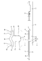
- FIG. 1 is a perspective view showing a connection structure between a flat cable and terminal fittings in an embodiment of the present disclosure.
- FIG. 2 is a side view showing a connection structure between a flat cable and terminal fittings.
- 3 is a cross-sectional view taken along the line AA of FIG. 2.
- FIG. 4 is a plan view showing a state in which terminal fittings are connected to a plurality of band-shaped portions of the flat cable.
- connection structure of the flat cable and the terminal fitting of the present disclosure is (1) A flat cable and a terminal fitting connected to the flat cable are provided, and the flat cable includes a first connecting portion located at a front end portion of the flat cable and a rearward portion of the first connecting portion. and a second connection portion located at the terminal fitting, wherein the terminal fitting includes a first weld portion welded to the first connection portion, and a first weld portion located behind the first weld portion and connected to the second connection portion. and a second weld to be welded.
- connection portion between the second connection portion and the second weld portion when the flat cable is pulled backward, stress is generated in the connection portion between the second connection portion and the second weld portion, and the connection portion between the first connection portion and the first weld portion is stressed.
- the generated stress can be relaxed. Therefore, even if an external force acts on the flat cable, the connection between the first connecting portion and the first welding portion can be maintained in good condition, and a decrease in connection reliability can be suppressed.
- the flat cable has a bent portion between the first connection portion and the second connection portion, and the terminal fitting has an elastic portion between the first weld portion and the second weld portion. It is preferable to have a deformable connecting portion. According to the above configuration, when the flat cable is pulled rearward, the connecting portion is elastically deformed while the bent portion is deformed so as to extend. Stress can be relieved better.
- the connecting portion is connected to the first welded portion and the second welded portion via a first boundary portion and a second boundary portion, respectively, and It is preferable that all of the portions are formed in a curved shape. According to the above configuration, since the stress can be dispersed in each of the curvilinear first boundary portion and the second boundary portion, the stress generated in the connecting portion between the first connection portion and the second connection portion can be further reduced. Good relief.
- the flat cable has a second reinforcing plate that overlaps the other surface of the second connection portion. and good. According to the above configuration, since the second connecting portion is reinforced by the second reinforcing plate, the connection between the second connecting portion and the second welding portion can be strengthened. When an external force acts on the flat cable, it is possible to prevent the flat cable from breaking at the portion corresponding to the second connecting portion.
- the flat cable has a first reinforcing plate that overlaps the other surface of the first connection portion. and good. According to the above configuration, since the first connecting portion is reinforced by the first reinforcing plate, the connection between the first connecting portion and the first welding portion can be strengthened. By reinforcing the first connecting portion with the first reinforcing plate, the reliability of electrical connection between the first connecting portion and the first welding portion can be further improved.
- This embodiment includes a flat cable 60 and terminal fittings 10 .
- Terminal fitting 10 is electrically and mechanically connected to flat cable 60 .
- the end of the flat cable 60 to which the terminal fitting 10 is connected is the front side, and the opposite side is the rear side.
- the right side of FIG. 2 is the front side.
- the width direction is synonymous with the left-right direction, and corresponds to the left-right direction in FIGS.
- the flat cable 60 is a flat conductor, and in the case of the present embodiment, is configured by a flexible printed circuit (FPC). Although not shown, the flat cable 60 has a plurality of conductive paths formed on both sides or one side of an insulating film and a protective film covering the conductive paths.
- FPC flexible printed circuit
- the flat cable 60 has a wide main body 61 and a plurality of narrow connecting bands 62 protruding forward from the front end of the main body 61 in a comb shape.
- Each connection band 62 has a conductive path and is arranged parallel to each other.
- the connection band 62 has a strip shape extending in the front-rear direction, and has a constant width and thickness over its entire length.
- a front portion of the flat cable 60 is accommodated in the connector housing 50 together with the plurality of terminal fittings 10 .
- the flat cable 60 has a portion pulled out rearward from the connector housing 50 .
- the flat cable 60 is held in the connector housing 50 by fitting projections 51 formed in the connector housing 50 into holes 63 formed in the main body 61 .
- the terminal fitting 10 is formed by press-molding a conductive metal plate material. As shown in FIG. 1, the terminal fitting 10 is a female terminal and has a box portion 11 in the shape of a rectangular tube at the front. A tab of a male terminal attached to a mating connector (not shown) is inserted from the front into the box portion 11 of the terminal fitting 10 and connected.
- the terminal fitting 10 has a rectangular tube-shaped base portion 12 behind the box portion 11 . Between the box portion 11 and the base portion 12, a connecting portion 13 having a concave cross section is provided. The box portion 11 and the base portion 12 are connected via the connecting portion 13 .
- the base 12 includes a bottom plate 14, a pair of side plates 15 rising from both ends in the width direction of the bottom plate 14, and a pair of top plates 16 projecting inward in the width direction from the upper ends of the pair of side plates 15. have.
- the inner edges in the width direction of both top plates 16 are arranged to face each other in the width direction central portion of the base portion 12 while facing each other along the front-rear direction.
- the base 12 includes a first welded portion 17 located in the front portion, a second welded portion 18 located in the rear portion, and a weld between the first welded portion 17 and the second welded portion 18 . and a connecting portion 19 located at the .
- the first welded portion 17 and the second welded portion 18 have rigidity to maintain a constant shape.
- the connecting portion 19 is elastically deformable in a direction crossing the front-rear direction.
- the first welded portion 17 and the second welded portion 18 both have a rectangular cross section, and have a bottom plate 14 , both side plates 15 and both top plates 16 .
- the first welded portion 17 is longer in the front-rear direction than the second welded portion 18 , and has a length that is at least twice as long as the second welded portion 18 in the case of the present embodiment.
- the lower portions of the side plates 15 and the front ends of the bottom plate 14 at the first welded portion 17 are integrally connected to the connecting portion 13 .
- the first welded portion 17 and the second welded portion 18 have, as shown in FIG. is doing.
- both side plates 15 and both top plates 16 at the first welded portion 17 constitute a first end 23 along the vertical direction.
- Front ends of the side plates 15 and the top plate 16 at the second welded portion 18 constitute a second end 24 extending in the vertical direction.
- the first end 23 and the second end 24 are arranged parallel to each other at a constant interval.
- the connecting portion 19 has the bottom plate 14, it does not have both top plates 16 and is open upward.
- the height of the side plates 15 of the connecting portion 19 is half or less of the height of the side plates 15 of the first welded portion 17 and the second welded portion 18 .
- the upper ends of the side plates 15 of the connecting portion 19 are formed in a curved line as a whole when viewed from the side. Specifically, as shown in FIG. 2 , the upper ends of the side plates 15 of the connecting portion 19 are composed of a linear portion 25 extending linearly in the front-rear direction and a first end extending from the front end of the linear portion 25 in a side view.
- the straight portion 25 is arranged in the front-rear direction central portion of the connecting portion 19 .
- the first boundary portion 26 and the second boundary portion 27 are line-symmetrical to each other when viewed from the side.
- connection band 62 of the flat cable 60 has, as shown in FIG. 2 connection part 65 and .
- soldering is performed by a reflow method.
- the first connecting portion 64 is arranged at the front end portion of the connecting band 62 .
- the second connection portion 65 is arranged behind the first connection portion 64 and away from the first connection portion 64 .
- the connecting band 62 has a bending portion 66 that bends upward in a mountain shape between the first connecting portion 64 and the second connecting portion 65 .
- the bent portion 66 is arranged above the connecting portion 19 and away from the connecting portion 19 .
- the first connecting portion 64 , the bent portion 66 and the second connecting portion 65 are formed continuously rearward from the front end of the connection band 62 at the front end portion of the flat cable 60 .
- a first reinforcing plate having a rigidity higher than that of the first connecting portion 64 is provided on the upper surface of the first connecting portion 64 of the connecting band 62 , which is the surface opposite to the surface soldered to the first joint surface 21 . 71 is installed. Similarly, of the two surfaces of the second connection portion 65 in the connection band 62 , the upper surface, which is the surface opposite to the surface soldered to the second bonding surface 22 , is also provided with a second connection portion 65 having higher rigidity than the second connection portion 65 . 2 reinforcing plate 72 is installed.
- the first reinforcing plate 71 and the second reinforcing plate 72 are both made of synthetic resin and have a strip shape extending in the front-rear direction. pasted through.
- the first connecting portion 64 is sandwiched and held between the first reinforcing plate 71 and the first welding portion 17 .
- the second connecting portion 65 is sandwiched and held between the second reinforcing plate 72 and the second welding portion 18 .
- the bent portion 66 is arranged between the rear end of the first reinforcing plate 71 and the front end of the second reinforcing plate 72 .
- the first reinforcing plate 71 has a length corresponding to that of the first connecting portion 64 in the front-rear direction, and is arranged so as to entirely overlap the first connecting portion 64 .
- the second reinforcing plate 72 has a length that exceeds the second connection portion 65 in the front-rear direction, the front portion entirely overlaps the second connection portion 65, and the rear portion protrudes rearward from the second connection portion 65. It is
- connection structure After the first welded portion 17 and the second welded portion 18 are solder-welded to the connection band 62 of the flat cable 60, the flat cable 60 is pulled backward, and the flat cable 60 is subjected to a backward external force F (see FIG. 2). may work.
- a backward external force F acts on the flat cable 60, stress is generated in the connecting portion between the second joint surface 22 of the second welded portion 18 and the second connection portion 65. Mechanical connection with portion 65 is maintained. Since the second connecting portion 65 is reinforced by the second reinforcing plate 72, the stability of the connection between the second welding portion 18 and the second connecting portion 65 is also ensured.
- the connecting portion 19 is elastically deformed while the bending portion 66 is deformed so that the external force F is transferred from the second welded portion 18 to the first welded portion 17 side. transmission can be suppressed.
- both the first boundary portion 26 and the second boundary portion 27 of the connecting portion 19 are formed in a curved shape, the stress generated at the connecting portion 19 is applied to the first boundary portion 26 and the second boundary portion 27 respectively. can be efficiently distributed to
- the stress generated in the connecting portion between the first joint surface 21 of the first welded portion 17 and the second connecting portion 65 is alleviated. Further, since the first connection portion 64 is reinforced by the first reinforcing plate 71, the facing state between the first joint surface 21 of the first weld portion 17 and the second connection portion 65 is maintained well. As a result, the electrical connection between the first welded portion 17 and the first connection portion 64 is also well maintained.
- the stress generated at the connecting portion between the first connecting portion 64 and the first welded portion 17 can be alleviated. . Therefore, even if the external force F acts on the flat cable 60, the connection between the first connection portion 64 and the first welding portion 17 can be maintained in good condition, and the deterioration of the connection reliability can be suppressed. .
- the connecting portion 19 is elastically deformed while the bending portion 66 is deformed so as to elongate, thereby more favorably reducing the stress generated in the connecting portion between the first connecting portion 64 and the first welding portion 17. be able to.
- connection portion between the first connection portion 64 and the second connection portion 65 can be can better relax the stress that occurs in the
- the second connecting portion 65 is reinforced by the second reinforcing plate 72, the connection between the second connecting portion 65 and the second welded portion 18 can be made strong.
- an external force F acts on the flat cable 60 , it is possible to prevent the flat cable 60 from being broken at the portion corresponding to the second connecting portion 65 .
- the connection between the first connecting portion 64 and the first welding portion 17 can be made strong. As a result, the electrical connection reliability between the first connecting portion 64 and the first welding portion 17 can be further improved.
- the terminal fittings were female terminals, but in other embodiments, the terminal fittings may be male terminals.
- the bent portion is bent angularly, but in another embodiment, the bent portion may be bent in an arc shape.
- the bent portion has a shape that bends upward away from the connecting portion, but in another embodiment, the bent portion may have a shape that bends downward toward the connecting portion.
- the terminal fittings are connected to the flat cable by solder welding, but in other embodiments, the terminal fittings may be connected to the flat cable by ultrasonic welding or resistance welding.
- the terminal fitting has an elastically deformable connecting portion between the first welded portion and the second welded portion, but in another embodiment, the second welded portion and the second connection The terminal fitting need not have an elastically deformable connecting portion between the first welded portion and the second welded portion as long as the structure is such that the portions are mechanically stably connected.
Landscapes
- Coupling Device And Connection With Printed Circuit (AREA)
- Multi-Conductor Connections (AREA)
Abstract
Description
最初に本開示の実施態様を列記して説明する。
本開示のフラットケーブルと端子金具の接続構造は、
(1)フラットケーブルと、前記フラットケーブルに接続される端子金具と、を備え、前記フラットケーブルは、前記フラットケーブルの前端部に位置する第1接続部と、前記第1接続部よりも後方に位置する第2接続部と、を有し、前記端子金具は、前記第1接続部に溶接される第1溶接部と、前記第1溶接部よりも後方に位置し、前記第2接続部に溶接される第2溶接部と、を有している。
上記構成によれば、フラットケーブルが後方に引っ張られたときに、第2接続部と第2溶接部との接続部位に応力を発生させ、第1接続部と第1溶接部との接続部位に発生する応力を緩和することができる。よって、フラットケーブルに外力が作用しても、第1接続部と第1溶接部との接続を良好に維持することができ、接続信頼性が低下するのを抑制することができる。
上記構成によれば、フラットケーブルが後方に引っ張られたときに、屈曲部が伸びるように変形しつつ繋ぎ部が弾性変形するため、第1接続部と第1溶接部との接続部位に発生する応力をより良好に緩和することができる。
上記構成によれば、曲線状をなす第1境界部と第2境界部のそれぞれに応力を分散させることができるので、第1接続部と第2接続部との接続部位に発生する応力をより良好に緩和することができる。
上記構成によれば、第2接続部が第2補強板で補強されるので、第2接続部と第2溶接部との接続を強固なものにすることができる。フラットケーブルに外力が作用したときには、フラットケーブルが第2接続部と対応する部位で破断されるのを防止することができる。
上記構成によれば、第1接続部が第1補強板で補強されるので、第1接続部と第1溶接部との接続を強固なものにすることができる。第1接続部が第1補強板で補強されることにより、第1接続部と第1溶接部との電気的な接続信頼性をより向上させることができる。
本開示の実施形態の具体例を、以下に図面を参照しつつ説明する。なお、本発明はこれらの例示に限定されるものではなく、請求の範囲によって示され、請求の範囲と均等の意味および範囲内でのすべての変更が含まれることが意図される。
フラットケーブル60は、平型導体であって、本実施形態の場合、フレキシブルプリント基板(Flexible Printed Circuit;FPC)で構成される。フラットケーブル60は、図示はしないが、絶縁フィルムの両面または片面に形成された複数の導電路と、導電路を覆う保護フィルムと、を有している。
端子金具10は、導電性の金属板材をプレス成形して形成される。この端子金具10は、図1に示すように、雌型端子であって、前部に、角筒状の箱部11を有している。端子金具10の箱部11には、前方から図示しない相手側コネクタに装着された雄型端子のタブが挿入されて接続される。
フラットケーブル60の接続帯62は、図2に示すように、第1接合面21に対面して半田付けされる第1接続部64と、第2接合面22に対面して半田付けされる第2接続部65と、を有している。本実施形態の場合、半田付けは、リフロー方式により行われる。第1接続部64は、接続帯62の前端部に配置されている。第2接続部65は、第1接続部64の後方に第1接続部64から離れて配置されている。
第1溶接部17と第2溶接部18がフラットケーブル60の接続帯62に半田溶接された後、フラットケーブル60が後方に引っ張られ、フラットケーブル60に後方への外力F(図2を参照)が作用することがある。このような外力Fがフラットケーブル60に作用すると、第2溶接部18の第2接合面22と第2接続部65との接続部分に応力が発生するが、第2溶接部18と第2接続部65との機械的な接続は維持される。第2接続部65が第2補強板72で補強されているため、第2溶接部18と第2接続部65との接続の安定性も確保される。
今回開示された実施の形態はすべての点で例示であって制限的なものではないと考えるべきである。
上記実施形態の場合、端子金具は雌型端子であったが、他の実施形態としては、端子金具は雄型端子であっても良い。
上記実施形態の場合、屈曲部は角張るように屈曲していたが、他の実施形態としては、屈曲部は弧状に湾曲するように屈曲していても良い。
上記実施形態の場合、屈曲部は繋ぎ部から離れる上向きに屈曲する形状であったが、他の実施形態としては、屈曲部は繋ぎ部に近づく下向きに屈曲する形状であっても良い。
上記実施形態の場合、端子金具はフラットケーブルに半田溶接により接続されていたが、他の実施形態としては、端子金具はフラットケーブルに超音波溶接や抵抗溶接により接続されていても良い。
上記実施形態の場合、端子金具は第1溶接部と第2溶接部との間に弾性変形可能な繋ぎ部を有していたが、他の実施形態としては、第2溶接部と第2接続部とが機械的に安定して接続される構造であれば、端子金具は第1溶接部と第2溶接部との間に弾性変形可能な繋ぎ部を有していなくても良い。
11…箱部
12…基部
13…連結部
14…底板
15…側板
16…天板
17…第1溶接部
18…第2溶接部
19…繋ぎ部
21…第1接合面
22…第2接合面
23…第1端
24…第2端
25…直線部
26…第1境界部
27…第2境界部
50…コネクタハウジング
51…突起
60…フラットケーブル
61…本体
62…接続帯
63…孔
64…第1接続部
65…第2接続部
66…屈曲部
71…第1補強板
72…第2補強板
F…外力
Claims (5)
- フラットケーブルと、前記フラットケーブルに接続される端子金具と、を備え、
前記フラットケーブルは、前記フラットケーブルの前端部に位置する第1接続部と、前記第1接続部よりも後方に位置する第2接続部と、を有し、
前記端子金具は、前記第1接続部に溶接される第1溶接部と、前記第1溶接部よりも後方に位置し、前記第2接続部に溶接される第2溶接部と、を有しているフラットケーブルと端子金具の接続構造。 - 前記フラットケーブルは、前記第1接続部と前記第2接続部との間に屈曲部を有し、
前記端子金具は、前記第1溶接部と前記第2溶接部との間に弾性変形可能な繋ぎ部を有している請求項1に記載のフラットケーブルと端子金具の接続構造。 - 前記繋ぎ部は、前記第1溶接部および前記第2溶接部のそれぞれに対して第1境界部および第2境界部を介して繋がっており、前記第1境界部および前記第2境界部は、いずれも曲線状に形成されている請求項2に記載のフラットケーブルと端子金具の接続構造。
- 前記第2溶接部が前記第2接続部の一方の面に溶接される場合に、前記フラットケーブルは、前記第2接続部の他方の面に重なる第2補強板を有している請求項1から請求項3のいずれか一項に記載のフラットケーブルと端子金具の接続構造。
- 前記第1溶接部が前記第1接続部の一方の面に溶接される場合に、前記フラットケーブルは、前記第1接続部の他方の面に重なる第1補強板を有している請求項1から請求項4のいずれか一項に記載のフラットケーブルと端子金具の接続構造。
Priority Applications (2)
| Application Number | Priority Date | Filing Date | Title |
|---|---|---|---|
| US18/289,502 US20240243497A1 (en) | 2021-05-14 | 2022-03-23 | Connection structure for connecting flat cable and terminal fitting |
| CN202280031321.0A CN117223174A (zh) | 2021-05-14 | 2022-03-23 | 扁平线缆和端子零件的连接结构 |
Applications Claiming Priority (2)
| Application Number | Priority Date | Filing Date | Title |
|---|---|---|---|
| JP2021-082090 | 2021-05-14 | ||
| JP2021082090A JP7530557B2 (ja) | 2021-05-14 | 2021-05-14 | フラットケーブルと端子金具の接続構造 |
Publications (1)
| Publication Number | Publication Date |
|---|---|
| WO2022239489A1 true WO2022239489A1 (ja) | 2022-11-17 |
Family
ID=84028146
Family Applications (1)
| Application Number | Title | Priority Date | Filing Date |
|---|---|---|---|
| PCT/JP2022/013347 Ceased WO2022239489A1 (ja) | 2021-05-14 | 2022-03-23 | フラットケーブルと端子金具の接続構造 |
Country Status (4)
| Country | Link |
|---|---|
| US (1) | US20240243497A1 (ja) |
| JP (1) | JP7530557B2 (ja) |
| CN (1) | CN117223174A (ja) |
| WO (1) | WO2022239489A1 (ja) |
Citations (6)
| Publication number | Priority date | Publication date | Assignee | Title |
|---|---|---|---|---|
| JP2002025653A (ja) * | 2000-07-03 | 2002-01-25 | Fujikura Ltd | フレキシブル基板の端子構造及びその製造方法 |
| JP2002270979A (ja) * | 2001-03-06 | 2002-09-20 | Aiwa Co Ltd | 導電部材の取付構造および取付方法 |
| JP2003157919A (ja) * | 2001-11-20 | 2003-05-30 | Canon Inc | フレキシブルフラットケーブル及びフレキシブルフラットケーブルとプリント配線板との実装方法 |
| JP2009076224A (ja) * | 2007-09-19 | 2009-04-09 | Yazaki Corp | 電線とプリント基板との接続構造 |
| JP2011113676A (ja) * | 2009-11-24 | 2011-06-09 | Yazaki Corp | フレキシブルフラットケーブルに対する端子の接続方法および端子 |
| JP2016225193A (ja) * | 2015-06-02 | 2016-12-28 | イリソ電子工業株式会社 | 端子付き平型導体及び端子と平型導体の接続方法 |
Family Cites Families (4)
| Publication number | Priority date | Publication date | Assignee | Title |
|---|---|---|---|---|
| FR2711853B1 (fr) * | 1993-10-26 | 1995-12-01 | Cinch Connecteurs Sa | Organe de contact électrique femelle. |
| FR2719706B1 (fr) * | 1994-05-03 | 1996-05-31 | Cinch Connecteurs Sa | Organe de contact électrique hermaphrodite. |
| JP3620014B2 (ja) * | 1999-08-04 | 2005-02-16 | 矢崎総業株式会社 | 雌端子及びその製造方法 |
| JP2003338334A (ja) * | 2002-05-20 | 2003-11-28 | Yazaki Corp | 雌端子およびその接続構造ならびにワイヤハーネス |
-
2021
- 2021-05-14 JP JP2021082090A patent/JP7530557B2/ja active Active
-
2022
- 2022-03-23 US US18/289,502 patent/US20240243497A1/en active Pending
- 2022-03-23 CN CN202280031321.0A patent/CN117223174A/zh active Pending
- 2022-03-23 WO PCT/JP2022/013347 patent/WO2022239489A1/ja not_active Ceased
Patent Citations (6)
| Publication number | Priority date | Publication date | Assignee | Title |
|---|---|---|---|---|
| JP2002025653A (ja) * | 2000-07-03 | 2002-01-25 | Fujikura Ltd | フレキシブル基板の端子構造及びその製造方法 |
| JP2002270979A (ja) * | 2001-03-06 | 2002-09-20 | Aiwa Co Ltd | 導電部材の取付構造および取付方法 |
| JP2003157919A (ja) * | 2001-11-20 | 2003-05-30 | Canon Inc | フレキシブルフラットケーブル及びフレキシブルフラットケーブルとプリント配線板との実装方法 |
| JP2009076224A (ja) * | 2007-09-19 | 2009-04-09 | Yazaki Corp | 電線とプリント基板との接続構造 |
| JP2011113676A (ja) * | 2009-11-24 | 2011-06-09 | Yazaki Corp | フレキシブルフラットケーブルに対する端子の接続方法および端子 |
| JP2016225193A (ja) * | 2015-06-02 | 2016-12-28 | イリソ電子工業株式会社 | 端子付き平型導体及び端子と平型導体の接続方法 |
Also Published As
| Publication number | Publication date |
|---|---|
| CN117223174A (zh) | 2023-12-12 |
| US20240243497A1 (en) | 2024-07-18 |
| JP2022175569A (ja) | 2022-11-25 |
| JP7530557B2 (ja) | 2024-08-08 |
Similar Documents
| Publication | Publication Date | Title |
|---|---|---|
| JP7713330B2 (ja) | メス型端子、コネクタ、端子付き電線、コネクタ付き電線及びワイヤーハーネス | |
| JP6293431B2 (ja) | 電気コネクタ | |
| KR101488463B1 (ko) | 압착 단자, 접속 구조체 및 커넥터 | |
| US9882306B2 (en) | Cable connector and carrier module thereof | |
| JP6510666B2 (ja) | 導電部材モジュールおよび電池パック | |
| CN105940558B (zh) | 接地端子单元 | |
| JP4618745B1 (ja) | 電気コネクタ | |
| JP2012532422A (ja) | 基板対基板タイプのコネクタ | |
| JP6448925B2 (ja) | コネクタ | |
| JP7803879B2 (ja) | メス型端子、コネクタ、バスバー、端子付き電線、コネクタ付き電線及びワイヤーハーネス | |
| JP7623243B2 (ja) | メス型端子、コネクタ、端子付き電線、コネクタ付き電線及びワイヤーハーネス | |
| KR100920426B1 (ko) | 기판 대 기판 타입 커넥터 | |
| US7458848B2 (en) | Connector | |
| WO2022239489A1 (ja) | フラットケーブルと端子金具の接続構造 | |
| WO2022158295A1 (ja) | 配線モジュール | |
| WO2020085056A1 (ja) | コネクタ | |
| JP6307573B1 (ja) | ケーブル固定構造 | |
| JP7640399B2 (ja) | メス型端子、コネクタ、端子付き電線、コネクタ付き電線及びワイヤーハーネス | |
| CN111934112A (zh) | 电连接器 | |
| JP2020102389A (ja) | 基板用コネクタ | |
| KR101967506B1 (ko) | 암형 전기 단자 | |
| CN112514169B (zh) | 扁平电线的连接构造 | |
| US12620741B2 (en) | Female terminal, connector, busbar, terminal-equipped electric wire, connector-equipped electric wire, and wire harness | |
| US20240258724A1 (en) | Terminal fitting | |
| JP4494165B2 (ja) | ワイヤハーネス用ジョイントコネクタ |
Legal Events
| Date | Code | Title | Description |
|---|---|---|---|
| 121 | Ep: the epo has been informed by wipo that ep was designated in this application |
Ref document number: 22807194 Country of ref document: EP Kind code of ref document: A1 |
|
| WWE | Wipo information: entry into national phase |
Ref document number: 202280031321.0 Country of ref document: CN |
|
| WWE | Wipo information: entry into national phase |
Ref document number: 18289502 Country of ref document: US |
|
| NENP | Non-entry into the national phase |
Ref country code: DE |
|
| 122 | Ep: pct application non-entry in european phase |
Ref document number: 22807194 Country of ref document: EP Kind code of ref document: A1 |