WO2022239292A1 - 造粒機,混練調整機構及び樹脂ペレット製造方法 - Google Patents
造粒機,混練調整機構及び樹脂ペレット製造方法 Download PDFInfo
- Publication number
- WO2022239292A1 WO2022239292A1 PCT/JP2021/048589 JP2021048589W WO2022239292A1 WO 2022239292 A1 WO2022239292 A1 WO 2022239292A1 JP 2021048589 W JP2021048589 W JP 2021048589W WO 2022239292 A1 WO2022239292 A1 WO 2022239292A1
- Authority
- WO
- WIPO (PCT)
- Prior art keywords
- screw
- kneading
- flow path
- section
- molten resin
- Prior art date
- Legal status (The legal status is an assumption and is not a legal conclusion. Google has not performed a legal analysis and makes no representation as to the accuracy of the status listed.)
- Ceased
Links
Images









Classifications
-
- B—PERFORMING OPERATIONS; TRANSPORTING
- B29—WORKING OF PLASTICS; WORKING OF SUBSTANCES IN A PLASTIC STATE IN GENERAL
- B29B—PREPARATION OR PRETREATMENT OF THE MATERIAL TO BE SHAPED; MAKING GRANULES OR PREFORMS; RECOVERY OF PLASTICS OR OTHER CONSTITUENTS OF WASTE MATERIAL CONTAINING PLASTICS
- B29B9/00—Making granules
- B29B9/12—Making granules characterised by structure or composition
-
- B—PERFORMING OPERATIONS; TRANSPORTING
- B29—WORKING OF PLASTICS; WORKING OF SUBSTANCES IN A PLASTIC STATE IN GENERAL
- B29B—PREPARATION OR PRETREATMENT OF THE MATERIAL TO BE SHAPED; MAKING GRANULES OR PREFORMS; RECOVERY OF PLASTICS OR OTHER CONSTITUENTS OF WASTE MATERIAL CONTAINING PLASTICS
- B29B7/00—Mixing; Kneading
- B29B7/30—Mixing; Kneading continuous, with mechanical mixing or kneading devices
- B29B7/34—Mixing; Kneading continuous, with mechanical mixing or kneading devices with movable mixing or kneading devices
- B29B7/38—Mixing; Kneading continuous, with mechanical mixing or kneading devices with movable mixing or kneading devices rotary
- B29B7/40—Mixing; Kneading continuous, with mechanical mixing or kneading devices with movable mixing or kneading devices rotary with single shaft
- B29B7/42—Mixing; Kneading continuous, with mechanical mixing or kneading devices with movable mixing or kneading devices rotary with single shaft with screw or helix
- B29B7/421—Mixing; Kneading continuous, with mechanical mixing or kneading devices with movable mixing or kneading devices rotary with single shaft with screw or helix with screw and additionally other mixing elements on the same shaft, e.g. paddles, discs, bearings, rotor blades of the Banbury type
-
- B—PERFORMING OPERATIONS; TRANSPORTING
- B29—WORKING OF PLASTICS; WORKING OF SUBSTANCES IN A PLASTIC STATE IN GENERAL
- B29B—PREPARATION OR PRETREATMENT OF THE MATERIAL TO BE SHAPED; MAKING GRANULES OR PREFORMS; RECOVERY OF PLASTICS OR OTHER CONSTITUENTS OF WASTE MATERIAL CONTAINING PLASTICS
- B29B7/00—Mixing; Kneading
- B29B7/30—Mixing; Kneading continuous, with mechanical mixing or kneading devices
- B29B7/34—Mixing; Kneading continuous, with mechanical mixing or kneading devices with movable mixing or kneading devices
-
- B—PERFORMING OPERATIONS; TRANSPORTING
- B29—WORKING OF PLASTICS; WORKING OF SUBSTANCES IN A PLASTIC STATE IN GENERAL
- B29B—PREPARATION OR PRETREATMENT OF THE MATERIAL TO BE SHAPED; MAKING GRANULES OR PREFORMS; RECOVERY OF PLASTICS OR OTHER CONSTITUENTS OF WASTE MATERIAL CONTAINING PLASTICS
- B29B7/00—Mixing; Kneading
- B29B7/30—Mixing; Kneading continuous, with mechanical mixing or kneading devices
- B29B7/34—Mixing; Kneading continuous, with mechanical mixing or kneading devices with movable mixing or kneading devices
- B29B7/38—Mixing; Kneading continuous, with mechanical mixing or kneading devices with movable mixing or kneading devices rotary
- B29B7/46—Mixing; Kneading continuous, with mechanical mixing or kneading devices with movable mixing or kneading devices rotary with more than one shaft
- B29B7/48—Mixing; Kneading continuous, with mechanical mixing or kneading devices with movable mixing or kneading devices rotary with more than one shaft with intermeshing devices, e.g. screws
- B29B7/488—Parts, e.g. casings, sealings; Accessories, e.g. flow controlling or throttling devices
-
- B—PERFORMING OPERATIONS; TRANSPORTING
- B29—WORKING OF PLASTICS; WORKING OF SUBSTANCES IN A PLASTIC STATE IN GENERAL
- B29B—PREPARATION OR PRETREATMENT OF THE MATERIAL TO BE SHAPED; MAKING GRANULES OR PREFORMS; RECOVERY OF PLASTICS OR OTHER CONSTITUENTS OF WASTE MATERIAL CONTAINING PLASTICS
- B29B7/00—Mixing; Kneading
- B29B7/30—Mixing; Kneading continuous, with mechanical mixing or kneading devices
- B29B7/58—Component parts, details or accessories; Auxiliary operations
-
- B—PERFORMING OPERATIONS; TRANSPORTING
- B29—WORKING OF PLASTICS; WORKING OF SUBSTANCES IN A PLASTIC STATE IN GENERAL
- B29B—PREPARATION OR PRETREATMENT OF THE MATERIAL TO BE SHAPED; MAKING GRANULES OR PREFORMS; RECOVERY OF PLASTICS OR OTHER CONSTITUENTS OF WASTE MATERIAL CONTAINING PLASTICS
- B29B7/00—Mixing; Kneading
- B29B7/30—Mixing; Kneading continuous, with mechanical mixing or kneading devices
- B29B7/58—Component parts, details or accessories; Auxiliary operations
- B29B7/72—Measuring, controlling or regulating
-
- B—PERFORMING OPERATIONS; TRANSPORTING
- B29—WORKING OF PLASTICS; WORKING OF SUBSTANCES IN A PLASTIC STATE IN GENERAL
- B29B—PREPARATION OR PRETREATMENT OF THE MATERIAL TO BE SHAPED; MAKING GRANULES OR PREFORMS; RECOVERY OF PLASTICS OR OTHER CONSTITUENTS OF WASTE MATERIAL CONTAINING PLASTICS
- B29B9/00—Making granules
- B29B9/02—Making granules by dividing preformed material
- B29B9/06—Making granules by dividing preformed material in the form of filamentary material, e.g. combined with extrusion
-
- B—PERFORMING OPERATIONS; TRANSPORTING
- B29—WORKING OF PLASTICS; WORKING OF SUBSTANCES IN A PLASTIC STATE IN GENERAL
- B29C—SHAPING OR JOINING OF PLASTICS; SHAPING OF MATERIAL IN A PLASTIC STATE, NOT OTHERWISE PROVIDED FOR; AFTER-TREATMENT OF THE SHAPED PRODUCTS, e.g. REPAIRING
- B29C48/00—Extrusion moulding, i.e. expressing the moulding material through a die or nozzle which imparts the desired form; Apparatus therefor
- B29C48/03—Extrusion moulding, i.e. expressing the moulding material through a die or nozzle which imparts the desired form; Apparatus therefor characterised by the shape of the extruded material at extrusion
- B29C48/04—Particle-shaped
-
- B—PERFORMING OPERATIONS; TRANSPORTING
- B29—WORKING OF PLASTICS; WORKING OF SUBSTANCES IN A PLASTIC STATE IN GENERAL
- B29B—PREPARATION OR PRETREATMENT OF THE MATERIAL TO BE SHAPED; MAKING GRANULES OR PREFORMS; RECOVERY OF PLASTICS OR OTHER CONSTITUENTS OF WASTE MATERIAL CONTAINING PLASTICS
- B29B7/00—Mixing; Kneading
- B29B7/30—Mixing; Kneading continuous, with mechanical mixing or kneading devices
- B29B7/58—Component parts, details or accessories; Auxiliary operations
- B29B7/584—Component parts, details or accessories; Auxiliary operations for mixers with rollers, e.g. wedges, guides, pressing means, thermal conditioning
- B29B7/586—Drives
-
- B—PERFORMING OPERATIONS; TRANSPORTING
- B29—WORKING OF PLASTICS; WORKING OF SUBSTANCES IN A PLASTIC STATE IN GENERAL
- B29B—PREPARATION OR PRETREATMENT OF THE MATERIAL TO BE SHAPED; MAKING GRANULES OR PREFORMS; RECOVERY OF PLASTICS OR OTHER CONSTITUENTS OF WASTE MATERIAL CONTAINING PLASTICS
- B29B7/00—Mixing; Kneading
- B29B7/30—Mixing; Kneading continuous, with mechanical mixing or kneading devices
- B29B7/58—Component parts, details or accessories; Auxiliary operations
- B29B7/584—Component parts, details or accessories; Auxiliary operations for mixers with rollers, e.g. wedges, guides, pressing means, thermal conditioning
- B29B7/588—Component parts, details or accessories; Auxiliary operations for mixers with rollers, e.g. wedges, guides, pressing means, thermal conditioning cutting devices, e.g. movable cutting devices
-
- B—PERFORMING OPERATIONS; TRANSPORTING
- B29—WORKING OF PLASTICS; WORKING OF SUBSTANCES IN A PLASTIC STATE IN GENERAL
- B29C—SHAPING OR JOINING OF PLASTICS; SHAPING OF MATERIAL IN A PLASTIC STATE, NOT OTHERWISE PROVIDED FOR; AFTER-TREATMENT OF THE SHAPED PRODUCTS, e.g. REPAIRING
- B29C48/00—Extrusion moulding, i.e. expressing the moulding material through a die or nozzle which imparts the desired form; Apparatus therefor
- B29C48/25—Component parts, details or accessories; Auxiliary operations
- B29C48/36—Means for plasticising or homogenising the moulding material or forcing it through the nozzle or die
- B29C48/395—Means for plasticising or homogenising the moulding material or forcing it through the nozzle or die using screws surrounded by a cooperating barrel, e.g. single screw extruders
- B29C48/40—Means for plasticising or homogenising the moulding material or forcing it through the nozzle or die using screws surrounded by a cooperating barrel, e.g. single screw extruders using two or more parallel screws or at least two parallel non-intermeshing screws, e.g. twin screw extruders
-
- B—PERFORMING OPERATIONS; TRANSPORTING
- B29—WORKING OF PLASTICS; WORKING OF SUBSTANCES IN A PLASTIC STATE IN GENERAL
- B29C—SHAPING OR JOINING OF PLASTICS; SHAPING OF MATERIAL IN A PLASTIC STATE, NOT OTHERWISE PROVIDED FOR; AFTER-TREATMENT OF THE SHAPED PRODUCTS, e.g. REPAIRING
- B29C48/00—Extrusion moulding, i.e. expressing the moulding material through a die or nozzle which imparts the desired form; Apparatus therefor
- B29C48/25—Component parts, details or accessories; Auxiliary operations
- B29C48/36—Means for plasticising or homogenising the moulding material or forcing it through the nozzle or die
- B29C48/50—Details of extruders
- B29C48/505—Screws
- B29C48/565—Screws having projections other than the thread, e.g. pins
-
- B—PERFORMING OPERATIONS; TRANSPORTING
- B29—WORKING OF PLASTICS; WORKING OF SUBSTANCES IN A PLASTIC STATE IN GENERAL
- B29C—SHAPING OR JOINING OF PLASTICS; SHAPING OF MATERIAL IN A PLASTIC STATE, NOT OTHERWISE PROVIDED FOR; AFTER-TREATMENT OF THE SHAPED PRODUCTS, e.g. REPAIRING
- B29C48/00—Extrusion moulding, i.e. expressing the moulding material through a die or nozzle which imparts the desired form; Apparatus therefor
- B29C48/25—Component parts, details or accessories; Auxiliary operations
- B29C48/36—Means for plasticising or homogenising the moulding material or forcing it through the nozzle or die
- B29C48/50—Details of extruders
- B29C48/68—Barrels or cylinders
-
- B—PERFORMING OPERATIONS; TRANSPORTING
- B29—WORKING OF PLASTICS; WORKING OF SUBSTANCES IN A PLASTIC STATE IN GENERAL
- B29C—SHAPING OR JOINING OF PLASTICS; SHAPING OF MATERIAL IN A PLASTIC STATE, NOT OTHERWISE PROVIDED FOR; AFTER-TREATMENT OF THE SHAPED PRODUCTS, e.g. REPAIRING
- B29C48/00—Extrusion moulding, i.e. expressing the moulding material through a die or nozzle which imparts the desired form; Apparatus therefor
- B29C48/25—Component parts, details or accessories; Auxiliary operations
- B29C48/36—Means for plasticising or homogenising the moulding material or forcing it through the nozzle or die
- B29C48/50—Details of extruders
- B29C48/68—Barrels or cylinders
- B29C48/685—Barrels or cylinders characterised by their inner surfaces, e.g. having grooves, projections or threads
-
- B—PERFORMING OPERATIONS; TRANSPORTING
- B29—WORKING OF PLASTICS; WORKING OF SUBSTANCES IN A PLASTIC STATE IN GENERAL
- B29C—SHAPING OR JOINING OF PLASTICS; SHAPING OF MATERIAL IN A PLASTIC STATE, NOT OTHERWISE PROVIDED FOR; AFTER-TREATMENT OF THE SHAPED PRODUCTS, e.g. REPAIRING
- B29C48/00—Extrusion moulding, i.e. expressing the moulding material through a die or nozzle which imparts the desired form; Apparatus therefor
- B29C48/25—Component parts, details or accessories; Auxiliary operations
- B29C48/92—Measuring, controlling or regulating
Definitions
- the present invention relates to an apparatus and method for manufacturing resin pellets.
- Patent Literature 1 discloses an underwater cutting type granulator that cuts a molten resin extruded from a nozzle of a die head in water.
- the kneading adjustment mechanism includes a pair of movable members having a flow path forming surface forming a part of a flow path through which the kneaded molten resin is conveyed, and the flow path of each of the movable members. a screw disposed between the forming surfaces. At least one of the pair of movable members is operable to increase or decrease the gap between the flow path forming surface and the screw. Also, at least one protrusion is provided on the outer circumference of the screw.
- the molten resin is kneaded more uniformly.
- FIG. 1 is a schematic diagram showing the configuration of a granulator according to one embodiment
- FIG. It is a sectional view showing the structure of a kneading processing part.
- FIG. 4 is a perspective view showing the structure of a kneading adjusting section;
- FIG. 10 is a cross-sectional view showing the movable member rotated until the cross-sectional area of the gate portion is minimized;
- FIG. 10 is a cross-sectional view showing the movable member rotated until the cross-sectional area of the gate portion is maximized;
- FIG. 4 is a perspective view showing a screw that constitutes the kneading adjustment mechanism;
- 5B is a cross-sectional view showing the screw shown in FIG.
- FIG. 5 is a perspective view showing a modified example of a screw that constitutes the kneading adjustment mechanism.
- 6B is a cross-sectional view showing the screw shown in FIG. 6A and the movable member therearound;
- FIG. 10 is a perspective view showing another modified example of the screw that constitutes the kneading adjustment mechanism.
- 7B is a cross-sectional view showing the screw shown in FIG. 7A and a movable member therearound;
- FIG. 10 is a perspective view showing another modified example of the screw that constitutes the kneading adjustment mechanism.
- 8B is a cross-sectional view showing the screw shown in FIG.
- FIG. 10 is a perspective view showing another modified example of the screw that constitutes the kneading adjustment mechanism.
- 9B is a cross-sectional view showing the screw shown in FIG. 9A and the movable member therearound;
- FIG. It is a figure which shows the result of a simulation.
- FIG. 11 is a perspective view showing a screw included in a granulator according to another embodiment; 11B is a cross-sectional view showing the screw shown in FIG. 11A and a movable member therearound;
- FIG. 11 is a perspective view showing a screw included in a granulator according to another embodiment; 12B is a cross-sectional view showing the screw shown in FIG.
- FIG. 11 is a perspective view showing a screw included in a granulator according to another embodiment
- 13B is a cross-sectional view showing the screw shown in FIG. 13A and the movable member therearound
- FIG. 11 is a perspective view showing a screw included in a granulator according to another embodiment
- 14B is a cross-sectional view showing the screw shown in FIG. 14A and the movable member therearound;
- FIG. 1 is a schematic diagram showing the configuration of a granulator according to one embodiment.
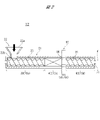
- FIG. 2 is a cross-sectional view showing the structure of a kneading section provided in the granulator shown in FIG.
- the granulator 1A shown in FIG. 1 has a main motor 10, a reduction gear 11, a kneading section 12, a gear pump 13, a foreign matter removing section (screen changer) 14, a die head 15 and a cutting section (pelletizer, cutter unit) 16. .
- the main motor 10 is a drive source for the kneading processing section 12 .
- Rotational driving force output from the main motor 10 is input to the screw 70 of the kneading processing section 12 via the speed reducer 11 to rotate the screw 70 .
- the speed reducer 11 reduces the speed of the rotational driving force output from the main motor 10 and increases the torque of the rotational driving force input to the screw 70 .
- the kneading processing section 12 melts and conveys the resin raw material by the rotating screw 70 . Further, the kneading processing section 12 conveys the melted resin raw material (molten resin) while kneading it with a rotating screw 70 .
- the kneading processing section 12 has a cylinder (barrel) 21 that forms a flow path (transportation path) 20 through which the resin raw material and molten resin are transported.
- a raw material hopper 22 is provided at one longitudinal end of the cylinder 21 .
- the raw material hopper 22 includes an upper opening 22 a and a lower opening 22 b that is smaller than the upper opening 22 a and communicates with the cylinder 21 .
- the resin raw material is put into the raw material hopper 22 from the upper opening 22a.
- the resin raw material put into the raw material hopper 22 drops into the cylinder 21 from the lower opening 22b. From another point of view, the resin raw material is supplied to the channel 20 via the raw material hopper 22 .
- the upper opening 22a of the raw material hopper 22 may be called “input port 22a”
- the lower opening 22b of the raw material hopper 22 may be called “discharge port 22b”.
- the resin raw material supplied to the flow path 20 is conveyed from one end side of the cylinder 21 provided with the raw material hopper 22 toward the other end side. That is, one end side (left side in FIG. 2) of the cylinder 21 provided with the raw material hopper 22 is the upstream side of the flow path 20, and the other end side (right side in FIG. 2) of the cylinder 21 is the downstream side of the flow path 20. is.
- the kneading processing section 12 includes at least a conveying section 30, a kneading section 40, a kneading adjusting section 50, a discharging section 60 and a screw 70 in addition to the cylinder 21 and the raw material hopper 22.
- the screw 70 is provided inside the cylinder 21 and is rotatably supported. From another point of view, the screw 70 is rotatably provided within the flow path 20 . As described above, the screw 70 is rotationally driven by the main motor 10 .
- a similar screw 70 is provided behind the screw 70 shown in FIG. 2 (see FIG. 1).
- These two screws 70 are arranged parallel to each other and are similarly rotationally driven by the main motor 10 .
- the granulator 1A has two screws 70 parallel to each other and is generally called a "twin-screw granulator” or a “twin-screw extruder".
- the two screws 70 provided in the granulator 1A are collectively referred to as "screws 70".
- the description of the screw 70 shown in FIG. 2 is also the description of the other screw 70 not shown in FIG.
- the conveying section 30 , the kneading section 40 , the kneading adjusting section 50 and the discharging section 60 are provided on the channel 20 . Further, the conveying section 30, the kneading section 40, the kneading adjusting section 50 and the discharging section 60 are arranged in a line along the flow path 20 in this order. In other words, the conveying section 30, the kneading section 40, the kneading adjusting section 50 and the discharging section 60 are arranged in a line along the central axis X of the screw 70 in this order.
- the gear pump 13 supplies (pumps) the molten resin kneaded by the kneading processing section 12 to the die head 15 through the foreign matter removing section (screen changer) 14 .
- the gear pump 13 is driven by a motor 13a.
- the rotational driving force output from the motor 13a is input to the gear pump 13 via the reduction gear 13b.
- the foreign matter removing section 14 removes unnecessary components, residues, contaminants, etc. from the passing molten resin.
- the die head 15 is composed of a die holder, a die plate, a die plate cover, etc., and has a plurality of nozzles through which molten resin is extruded.
- the molten resin supplied to the die head 15 after passing through the foreign matter removing section 14 is extruded from the nozzle of the die head 15 to be formed into a strand shape (string shape, rope shape).
- the cutting section 16 includes a cutting processing section that receives the strand-shaped molten resin extruded from the nozzle of the die head 15 .
- the cutting processing section is provided on the flow path of water (pellet transport water) circulating in the resin pellet manufacturing system including the granulator 1A. During operation of the manufacturing system, the cutting process fills with pellet transport water. In other words, the molten resin molded into strands by the die head 15 is extruded into water (into pellet transportation water).
- a rotationally driven cutter head is provided in the cutting processing section of the cutting section 16 .
- a plurality of cutter blades are attached to the cutter head.
- the cutter head is driven by a motor 16a and cuts the strand-shaped molten resin extruded from the die head 15 into a predetermined length.
- resin pellets are produced through the following steps.
- a resin raw material is supplied to the kneading processing section 12 . More specifically, resin raw material is put into the raw material hopper 22 .
- the resin raw material supplied to the kneading processing section 12 is, for example, a thermoplastic resin. More specifically, for example, a polyolefin resin having a bimodal structure is supplied to the kneading processing section 12 . Additives and the like are added to the resin raw material as necessary.
- the resin raw material supplied to the kneading processing section 12 is conveyed from the upstream side to the downstream side of the flow path 20 by the rotating screw 70 .
- the resin raw material (molten resin) conveyed through the flow path 20 is melted and kneaded while being conveyed. More specifically, the resin raw material (molten resin) is melted and kneaded while passing through the conveying section 30, the kneading section 40, the kneading adjusting section 50 and the discharging section 60 in this order.
- Each step will be described in more detail below.
- the resin raw material supplied to the conveying section 30 is melted and conveyed to the downstream side of the flow path 20 (melting step).
- the resin raw material (molten resin) melted in the melting step is conveyed to the kneading section 40 .
- the molten resin supplied to the kneading section 40 is kneaded (mixed) and conveyed to the further downstream side of the flow path 20 (kneading step).
- the resin raw material is melted mainly by the heat generated by the shearing action caused by the rotation of the screw 70 .
- the molten resin is kneaded (dispersion-mixed and distributed-mixed) mainly by shearing action and elongation action caused by rotation of the screw 70 .
- Heat generation of the molten resin continues even during the kneading process. At least, the temperature of the molten resin during the kneading process is maintained within a predetermined temperature range by heat generation.
- the resin raw material and the molten resin may be heated by a heating means such as a heater, and the resin raw material and the molten resin may be cooled by a cooling means.
- the molten resin kneaded in the kneading process is supplied (discharged) to the gear pump 13 shown in FIG.
- a process (kneading adjustment process) of adjusting the degree of kneading (kneading degree) of the molten resin in the kneading process is executed.
- the kneading adjustment unit 50 will be explained again later.
- the molten resin supplied to the gear pump 13 is supplied (pumped) to the die head 15 through the foreign matter removing section 14 .
- the foreign matter removing section 14 volatile components contained in the molten resin, catalyst residues, and foreign matter mixed from the outside are removed (foreign matter removing step).
- the molten resin pumped to the die head 15 is continuously extruded from multiple nozzles of the die head 15 (extrusion process).
- the molten resin is molded into a strand shape (string shape, rope shape) by passing through the nozzle of the die head 15 .
- the strand-shaped molten resin extruded from the nozzle of the die head 15 is cut to a predetermined length in the cutting processing section of the cutting section 16 and solidified (cutting/solidifying process, pelletizing process).
- the molten resin extruded into strands is divided into pellets.
- resin pellets having a predetermined size (length and thickness) are produced.
- the cutting processing section of the cutting section 16 is filled with water (pellet transportation water), and the molten resin is cut in water (pellet transportation water).
- Such a method of cutting molten resin in water is sometimes called "underwater cutting".
- resin pellets may be produced without circulating the pellet-transporting water.
- the molten resin extruded from the nozzle of the die head 15 is cut within the cutting processing section where pellet transport water does not exist. That is, the molten resin is pushed out into the air and cut.
- Such a method of cutting molten resin in the air is sometimes called "hot cutting".
- a mixture (slurry) of resin pellets and pellet-transporting water sent out from the cutting section is separated into resin pellets and pellet-transporting water (dehydration step). Then, the resin pellets separated from the pellet-transporting water are sent to a storage container such as a pellet silo (transfer step). Resin pellets are sent to a pellet silo by, for example, an air current generated by a blower.
- resin pellets are produced through the steps described above.
- the method for producing resin pellets can be modified in various ways according to the type and characteristics of resin raw materials and resin pellets.
- a dehydration step is followed by a drying step.
- water that has not been removed in the dehydration step is removed from the resin pellets using a centrifugal dehydrator or the like.
- a sorting step is performed to sort the resin pellets based on size.
- the kneading processing section 12 includes a conveying section 30, a kneading section 40, a kneading adjusting section 50 and a discharging section 60 which are provided along the longitudinal direction of the cylinder 21 (flow path 20) and the screw 70. have. From another point of view, the cylinder 21 (flow path 20) and the screw 70 can be classified into a conveying section 30, a kneading section 40, a kneading adjustment section 50 and a discharge section 60 based on their functions.
- the conveying section 30 is configured by part of the cylinder 21 and the screw 70.
- the kneading section 40 is composed of the cylinder 21 and another part of the screw 70
- the kneading adjusting section 50 is composed of another part of the screw 70
- the discharge section 60 is composed of another part of the cylinder 21 and the screw 70. It is composed by
- part of the cylinders 21 constituting the conveying section 30 is referred to as the "upstream section”
- another part of the cylinders 21 constituting the kneading section 40 is referred to as the “midstream section”
- the discharging section 60 is defined.
- another portion of the cylinder 21 that is connected to the air flow is sometimes called a "downstream portion" for distinction.
- downstream portion is merely a distinction for convenience of explanation.
- a part of the screw 70 constituting the conveying section 30 is referred to as a "conveying screw section 70a", and the other part of the screw 70 constituting the kneading section 40 is referred to as a "previous kneading screw section 70b.”
- the other part of the screw 70 constituting the kneading adjusting part 50 is called the “later kneading screw part 70c”
- the other part of the screw 70 constituting the discharging part 60 is called the “discharging screw part 70d”.
- Such a distinction is also merely a distinction for convenience of explanation.
- the screw 70 has flights or projections on a shaft 71 that extends from one end of the cylinder 21 to the other. More specifically, flights are provided on the outer peripheries of the conveying screw portion 70a, the pre-stage kneading screw portion 70b, and the discharge screw portion 70d of the screw 70 . A protruding portion is provided on the outer periphery of the post-stage kneading screw portion 70c of the screw 70 .
- the flights and protrusions provided on the screw 70 are formed by kneading discs, rotors, segments, etc. attached to the shaft 71 or integrally formed with the shaft 71 .
- the form (structure, shape, size, pitch, etc.) of the flights provided on the screw 70 is appropriately determined according to the purpose of each flight, the type of resin, and the like.
- the main purpose of the flights provided on a part of the screw 70 of the present embodiment is to convey the resin raw material and the molten resin.
- the main purpose of the flights provided in the other part of the screw 70 of the present embodiment is to knead the molten resin.
- the flights provided in the conveying screw portion 70a and the discharging screw portion 70d are formed by spiral blades integrally formed with the shaft 71.
- the flights provided in the front stage kneading screw portion 70b of the screw 70 are formed by a plurality of kneading discs or rotors attached to the shaft 71 .
- the protrusions provided on the post-stage kneading screw portion 70c of the screw 70 will be described later.
- FIG. 3 is a perspective view showing the structure of the kneading adjustment section 50. As shown in FIG. The kneading adjustment section 50 is provided above the flow path 20 and downstream of the kneading section 40 . The kneading adjustment section 50 forms part of the flow path 20 and includes a kneading adjustment mechanism 80 that adjusts the kneading degree of the molten resin.
- the kneading adjustment mechanism 80 adjusts the kneading degree of the molten resin by changing the cross-sectional area of a part of the flow path 20 formed by the kneading adjustment section 50 . Furthermore, the kneading adjustment mechanism 80 itself kneads the molten resin.
- the kneading adjustment mechanism 80 is composed of a pair of movable members 81 and 82, a holding block 83 and a screw 84.
- the screw 84 that constitutes the kneading adjustment mechanism 80 is part of the screw 70 . More specifically, the screw 84 constituting the kneading adjustment mechanism 80 is the post kneading screw portion 70 c of the screw 70 .
- the movable members 81 and 82 are rotatably held metal rods. Each of the movable members 81 and 82 is arranged between the midstream portion and the downstream portion of the cylinder 21 and rotatably held by a holding block 83 forming part of the flow path 20 .
- the holding block 83 is provided with an upper holding portion 83 a that crosses over the channel 20 and a lower holding portion 83 b that crosses below the channel 20 .
- the upper holding portion 83a and the lower holding portion 83b vertically cross the channel 20 and extend parallel to each other.
- the movable member 81 is inserted through the upper holding portion 83a, and the movable member 82 is inserted through the lower holding portion 83b. As a result, the movable member 81 vertically traverses above the channel 20 and the movable member 82 vertically traverses below the channel 20 . A portion of the outer peripheral surface of the movable member 81 is exposed to the flow path 20 , and a portion of the outer peripheral surface of the movable member 82 is also exposed to the flow path 20 . From another point of view, the movable members 81 and 82 form part of the flow path 20 together with the holding block 83 .
- both movable members On both sides in the longitudinal direction of each of the movable members 81 and 82, gears that mesh with each other are formed over the entire circumference.
- both movable members simultaneously rotate in opposite directions.
- the upper movable member 81 rotates clockwise
- the lower movable member 82 simultaneously rotates counterclockwise. That is, the two movable members 81 and 82 are interlocked and rotate in opposite directions.
- the cross-sectional area of a portion of the flow path 20 changes (increases or decreases) according to the rotation angle (rotation amount) of the movable members 81 and 82 .
- the kneading adjustment mechanism 80 is provided downstream of the kneading section 40 . More specifically, the kneading adjustment mechanism 80 is provided between the midstream portion and the downstream portion of the cylinder 21 . In other words, the kneading adjustment mechanism 80 is provided between the kneading section 40 and the discharging section 60 . As a result, the cross-sectional area of a part (region) of the channel 20 that connects the kneading section 40 and the discharge section 60 is changed by the kneading adjustment mechanism 80 . In the following description, a part (region) of the flow path 20 whose cross-sectional area is changed by the kneading adjustment mechanism 80 may be called "gate part G".
- the gate section G is located downstream of the kneading section 40 . Therefore, when the cross-sectional area of the gate portion G is changed by the kneading adjustment mechanism 80, the pressure (back pressure) of the molten resin at the gate portion G changes. Specifically, when the cross-sectional area of the gate portion G is reduced by the kneading adjustment mechanism 80, the pressure of the molten resin at the gate portion G increases. On the other hand, when the cross-sectional area of the gate portion G is enlarged by the kneading adjustment mechanism 80, the pressure of the molten resin at the gate portion G is reduced.
- the kneading adjustment mechanism 80 controls the pressure of the molten resin at the gate portion G by partially changing the cross-sectional area of the flow path 20, and adjusts the degree of kneading of the molten resin.
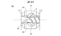
- FIG. 4A is a cross-sectional view showing the movable members 81 and 82 rotated until the cross-sectional area of the gate portion G is minimized.
- FIG. 4B is a cross-sectional view showing the movable members 81 and 82 rotated until the cross-sectional area of the gate portion G is maximized.
- the movable members 81 and 82 are provided with flow path forming surfaces 85 that form part of the flow path 20 (gate portion G).
- the flow path forming surfaces 85 of the respective movable members 81 and 82 have a curved surface shape following the outer shape of the screw 84 (the latter stage kneading screw portion 70c), and are arranged on both sides (up and down) in the radial direction of the screw 84.
- the screw 84 is arranged between the flow path forming surface 85 of the movable member 81 and the flow path forming surface 85 of the movable member 82 .
- the flow path forming surface 85 of the movable member 81 forming the upper side of the gate portion G faces approximately the upper half of the screw 84, and the flow path forming surface 85 of the movable member 82 forming the lower side of the gate portion G faces the screw. It generally faces the lower half of 84 .
- the flow path forming surface 85 of the movable member 81 faces the upper side of the outer peripheral surface of the rear kneading screw portion 70c
- the flow path forming surface 85 of the movable member 82 faces the lower side of the outer peripheral surface of the rear kneading screw portion 70c.
- the area on the screw 84 that faces the flow path forming surface 85 changes as the screw 84 rotates.
- the passage forming surface 85 and the screw 84 may face each other in parallel or may face each other obliquely.
- the pair of movable members 81 and 82 are operable to increase or decrease the gap (clearance) between the flow path forming surface 85 and the screw 84. As the gap (clearance) between the flow path forming surface 85 and the screw 84 increases or decreases, the cross-sectional area of the gate portion G expands or contracts.
- the cross-sectional area of the gate portion G gradually decreases as the movable members 81 and 82 shift from the fully open state to the fully closed state, and as the movable members 81 and 82 shift from the fully closed state to the fully open state. gradually expand.
- the cross-sectional area of the gate portion G can be enlarged or reduced. Also, by moving the movable members 81 and 82 up and down, the gap (clearance) between the flow path forming surface 85 and the screw 84 can be increased or decreased.
- the screw 84 has a shape capable of kneading the molten resin passing through the kneading adjusting section 50 . More specifically, the screw 84 has a shape capable of dispersing and mixing the molten resin passing through the kneading adjusting section 50 .
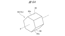
- FIG. 5A is a perspective view of the screw 84.
- FIG. FIG. 5B is a cross-sectional view of the screw 84 and its surrounding movable members 81 and 82 shown in FIG. 5A.
- the cross section of the screw 84 shown in FIG. 5B is a cross section perpendicular to the central axis X.
- the central axis X is the central axis of the screw 70 as well as the central axis of the screw 84 .
- the cross section of the screw 70 (screw 84) means a cross section perpendicular to the central axis X unless otherwise specified.
- the movable members 81 and 82 shown in FIG. 5B actually have shapes as shown in FIG. 3, and are schematically shown in FIG. 5B.
- At least one protrusion 86 is provided on the outer circumference of the screw 84 .
- the outer periphery of the screw 84 is provided with six protrusions 86 each having a corner. From another point of view, edges are provided at six locations in the circumferential direction of the screw 84 .
- the six projections 86 provided on the screw 84 are arranged at regular intervals (at intervals of 60 degrees) in the circumferential direction (rotational direction) of the screw 84 .
- Each projection 86 extends parallel to the central axis X of the screw 84 .
- line segments connecting the apexes (tips) 86a of the projections 86 within the cross section of the screw 84 form a regular polygon (regular six-hexagon). That is, the screw 84 has a regular hexagonal cross-sectional shape.
- a screw 84 having a protrusion 86 on its outer periphery generates an elongational flow in the molten resin passing through the kneading adjustment section 50 (gate section G). Specifically, when the screw 84 rotates, the flow path forming surface 85 relatively approaches and separates from the tip of the protrusion 86 of the screw 84 . As a result, the cross-sectional area of the flow channel continuously changes, and elongation deformation occurs in the molten resin.
- the kneading adjustment section 50 can obtain an elongation speed. That is, the molten resin kneaded (mixed) while passing through the kneading section 40 is also kneaded (mixed) while passing through the kneading adjustment section 50 .
- kneading may become excessive, while if the cross-sectional area of the flow path is too large, kneading may be insufficient. That is, if the clearance between the screw 84 and the flow path forming surface 85 is too small, there is a risk of excessive kneading. On the other hand, if the clearance between the screw 84 and the flow path forming surface 85 is too large, the kneading may become insufficient.
- the ratio (b/a) between the minimum clearance a and the maximum clearance b shown in FIG. 5B is preferably 4 or less.
- the minimum clearance a when the movable members 81 and 82 are in the fully closed state is preferably 1/10 or less of the inner diameter d of the gate portion G.
- the minimum clearance a shown in FIG. 5B is the clearance between the projection 86 of the screw 84 and the flow path forming surface 85. More specifically, it is the clearance between the tip of the protrusion 86 and the flow path forming surface 85 . Also, the maximum clearance b shown in FIG. 5B is the clearance between the flat portion between two adjacent protrusions 86 and the flow path forming surface 85 .
- protrusions 86 are provided on the outer circumference of the screw 84 .
- the number, shape, arrangement, etc. of the protrusions 86 provided on the outer circumference of the screw 84 are not limited. Therefore, some modifications of the screw 84 will be described below.
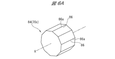
- FIG. 6A is a perspective view showing one modification of the screw 84.
- FIG. 6B is a cross-sectional view of the screw 84 and its surrounding movable members 81 and 82 shown in FIG. 6A.
- FIG. 7A is a perspective view showing another modification of the screw 84.
- FIG. 7B is a cross-sectional view of the screw 84 and its surrounding movable members 81 and 82 shown in FIG. 7A.
- ten protrusions 86 each having a corner are provided on the outer circumference of the screw 84 shown in Figs. 7A and 7B. These ten projections 86 are arranged at equal intervals (36 degrees intervals) in the circumferential direction (rotational direction) of the screw 84 . As a result, line segments connecting the vertices 86a of the projections 86 within the cross section of the screw 84 form regular polygons (regular decagons). That is, the screw 84 shown in FIGS. 7A and 7B has a regular decagonal cross-sectional shape.
- FIG. 8A is a perspective view showing another modification of the screw 84.
- FIG. 8B is a cross-sectional view of the screw 84 and its surrounding movable members 81 and 82 shown in FIG. 8A.
- protrusions 86 each having a corner are provided on the outer circumference of the screw 84 shown in FIGS. 8A and 8B. These 12 protrusions 86 are arranged at equal intervals (at intervals of 30 degrees) in the circumferential direction (rotational direction) of the screw 84 . As a result, line segments connecting the vertices 86a of the projections 86 within the cross section of the screw 84 form a regular polygon (regular dodecagon). That is, the screw 84 shown in FIGS. 8A and 8B has a regular dodecagonal cross-sectional shape.
- FIG. 9A is a perspective view showing another modification of the screw 84.
- FIG. 9B is a cross-sectional view of the screw 84 and its surrounding movable members 81 and 82 shown in FIG. 9A.
- 24 protrusions 86 each having a corner are provided on the outer periphery of the screw 84 shown in Figures 9A and 9B. These 24 protrusions 86 are arranged at regular intervals (15 degree intervals) in the circumferential direction (rotational direction) of the screw 84 . As a result, line segments connecting the vertices 86a of the projections 86 within the cross section of the screw 84 form a regular polygon (a regular 24-sided polygon). That is, the screw 84 shown in FIGS. 9A and 9B has a regular 24-sided cross-sectional shape.
- each screw is rotated at the same speed in a cylinder under the same conditions. It was also assumed that the outside diameter of each screw was the same or substantially the same. For a screw with a regular polygonal cross-sectional shape, the diameter of a circle connecting the vertices of each protrusion was taken as the outer diameter of the screw.
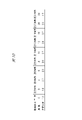
- Fig. 10 shows the comparison results of the elongation speed calculated by this simulation.
- the table of FIG. 10 shows the ratio of the extension rate obtained by each screw with a regular polygonal cross-section to the extension rate obtained by the screw with a circular cross-section.
- the screw 84 may have at least one projection 86, and its cross-sectional shape is not limited to a regular polygon. Therefore, the screw 84 in the above embodiment can be replaced with the screw 84 shown in FIGS. 11 to 14, for example.
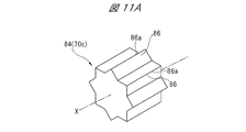
- FIG. 11A is a perspective view of a screw 84 provided in a granulator of another embodiment.
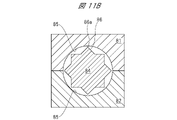
- FIG. 11B is a cross-sectional view of the screw 84 and its surrounding movable members 81 and 82 shown in FIG. 11A.
- Eight protrusions 86 having a triangular cross-sectional shape are provided on the outer circumference of the screw 84 shown in FIGS. 11A and 11B. From another point of view, this screw 84 has a generally star-shaped cross-sectional shape. From another point of view, the outer periphery of the screw 84 is provided with a plurality of peaks and valleys. Also, the peaks and valleys are alternately arranged in the circumferential direction.
- FIG. 12A is a perspective view of a screw 84 provided in a granulator of still another embodiment.
- FIG. 12B is a cross-sectional view of the screw 84 and its surrounding movable members 81 and 82 shown in FIG. 12A.
- protrusions 86 having a triangular (wedge-shaped) cross-sectional shape are provided on the outer circumference of the screw 84 shown in Figs. 12A and 12B.
- the protrusion 86 provided on the screw 84 shown in FIGS. 12A and 12B is sharper than the protrusion 86 provided on the screw 84 shown in FIGS. 11A and 11B, and They are lined up at a narrow pitch. From another point of view, a plurality of thorns are provided on the outer circumference of the screw 84 .
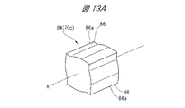
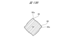
- FIG. 13A is a perspective view of a screw 84 provided in a granulator of still another embodiment.
- FIG. 13B is a cross-sectional view of the screw 84 shown in FIG. 13A.
- protrusions 86 are provided on the outer circumference of the screw 84 shown in FIGS. 13A and 13B. Furthermore, the outer peripheral surface of the screw 84 connecting the adjacent protrusions 86 is undulating (wavy). From another point of view, adjacent protrusions 86 are connected by curved surfaces. In the screw 84 shown in FIGS. 13A and 13B as well, the line segments connecting the vertices 86a of the projections 86 in the cross section perpendicular to the central axis X form a regular polygon (regular quadrangle). there is
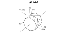
- FIG. 14A is a perspective view of a screw 84 provided in a granulator of still another embodiment.
- FIG. 14B is a cross-sectional view of the screw 84 shown in FIG. 14A.
- each protrusion 86 is provided on the outer circumference of the screw 84 shown in FIGS. 14A and 14B.
- This screw 84 has a regular hexagonal cross-sectional shape like the screw 84 shown in FIGS. 5A and 5B.
- each protrusion 86 provided on the screw 84 shown in FIGS. 5A and 5B extends parallel to the central axis X
- Each protrusion 86 provided on 84 extends in a direction intersecting the central axis X.
- each projection 86 provided on the screw 84 shown in FIGS. 14A and 14B spirally extends with the central axis X as a turning axis. 6 to 13, all the projections 86 provided on the screw 84 extend parallel to the central axis X.
- FIG. 14A and 14B spirally extends with the central axis X as a turning axis. 6 to 13
- all the projections 86 provided on the screw 84 extend parallel to the central axi
- This specification shows several examples of the shape of the screw 84 that constitutes the kneading adjustment mechanism 80 .
- the shape of screw 84 shown herein is just one example.
- the shape, size, number, pitch, etc. of the protrusions 86 provided on the screw 84 constituting the kneading adjustment mechanism 80 can be appropriately changed according to the stress acting on the molten resin passing through the kneading adjustment section 50 .
- the projections 86 do not have to be sharp.
- the tip of the protrusion 86 may be, for example, an arcuate surface. When the tip of the protrusion 86 is an arc surface, the midpoint of the arc corresponds to the vertex 86 a of the protrusion 86 .
- Granulators include at least twin-screw granulators and single-screw granulators. Twin-screw granulators also include at least continuous co-meshing twin-screw granulators and continuous counter-meshing non-meshing twin-screw granulators.
Landscapes
- Engineering & Computer Science (AREA)
- Mechanical Engineering (AREA)
- Processing And Handling Of Plastics And Other Materials For Molding In General (AREA)
- Extrusion Moulding Of Plastics Or The Like (AREA)
Abstract
Description
図1は、一実施形態に係る造粒機の構成を示す模式図である。図2は、図1に示される造粒機が備える混練処理部の構造を示す断面図である。図1に示される造粒機1Aは、メインモータ10,減速機11,混練処理部12,ギヤポンプ13,異物除去部(スクリーンチェンジャ)14,ダイヘッド15および切断部(ペレタイザ,カッターユニット)16を有する。
メインモータ10は、混練処理部12の駆動源である。メインモータ10から出力される回転駆動力は、減速機11を介して混練処理部12のスクリュー70に入力され、スクリュー70を回転させる。減速機11は、メインモータ10から出力される回転駆動力の速度を減じ、スクリュー70に入力される回転駆動力のトルクを増大させる。
混練処理部12は、回転するスクリュー70によって、樹脂原料を溶融させつつ搬送する。また、混練処理部12は、溶融された樹脂原料(溶融樹脂)を回転するスクリュー70によって混練しつつ搬送する。
再び図1を参照する。ギヤポンプ13は、混練処理部12によって混練された溶融樹脂を、異物除去部(スクリーンチェンジャ)14を通してダイヘッド15に供給(圧送)する。ギヤポンプ13は、モータ13aによって駆動される。モータ13aから出力される回転駆動力は、減速機13bを介してギヤポンプ13に入力される。異物除去部14は、通過する溶融樹脂から不要成分,残渣,混入物などを除去する。
ダイヘッド15は、ダイホルダ,ダイプレート,ダイプレートカバー等から構成されており、溶融樹脂が押し出される複数のノズルを備えている。異物除去部14を通過してダイヘッド15に供給された溶融樹脂は、ダイヘッド15のノズルから押し出されることにより、ストランド状(紐状、ロープ状)に成形される。
切断部16は、ダイヘッド15のノズルから押し出されるストランド状の溶融樹脂を受け入れる切断処理部を備えている。切断処理部は、造粒機1Aを含む樹脂ペレット製造システム内を循環する水(ペレット輸送水)の流路上に設けられている。製造システムの稼動中、切断処理部は、ペレット輸送水によって満たされる。つまり、ダイヘッド15によってストランド状に成形された溶融樹脂は、水中(ペレット輸送水中)に押し出される。
造粒機1Aでは、例えば、次のような工程によって樹脂ペレットが製造される。まず、混練処理部12に樹脂原料が供給される。より特定的には、原料ホッパ22に樹脂原料が投入される。混練処理部12に供給される樹脂原料は、例えば、熱可塑性樹脂である。より特定的には、例えば、バイモーダル構造を有するポリオレフィン系樹脂などが混練処理部12に供給される。樹脂原料には、必要に応じて添加剤などが加えられる。
次に、造粒機1Aの混練処理部12についてより詳しく説明する。図2に示されるように、混練処理部12は、シリンダ21(流路20)及びスクリュー70の長手方向に沿って設けられた搬送部30,混練部40,混練調整部50及び放出部60を有する。別の見方をすると、シリンダ21(流路20)及びスクリュー70は、機能に基づいて、搬送部30,混練部40,混練調整部50及び放出部60に区別することができる。
スクリュー70は、シリンダ21の一端から他端まで延びるシャフト71に設けられたフライトや突起部を備えている。より特定的には、スクリュー70の搬送スクリュー部70a,前段混練スクリュー部70b及び放出スクリュー部70dの外周には、フライトが設けられている。また、スクリュー70の後段混練スクリュー部70cの外周には、突起部が設けられている。
図3は、混練調整部50の構造を示す斜視図である。混練調整部50は、流路20上であって、混練部40よりも下流に設けられている。混練調整部50は、流路20の一部を形成するとともに、溶融樹脂の混練度を調整する混練調整機構80を備えている。
次に、混練調整機構80を構成しているスクリュー84の形状について説明する。なお、スクリュー84がスクリュー70の一部(後段混練スクリュー部70c)であることは、既述のとおりである。
図6Aは、スクリュー84の一変形例を示す斜視図である。図6Bは、図6Aに示されているスクリュー84及びその周囲の可動部材81,82の断面図である。
図7Aは、スクリュー84の他の一変形例を示す斜視図である。図7Bは、図7Aに示されているスクリュー84及びその周囲の可動部材81,82の断面図である。
図8Aは、スクリュー84の他の一変形例を示す斜視図である。図8Bは、図8Aに示されているスクリュー84及びその周囲の可動部材81,82の断面図である。
図9Aは、スクリュー84の他の一変形例を示す斜視図である。図9Bは、図9Aに示されているスクリュー84及びその周囲の可動部材81,82の断面図である。
次に、本実施形態の効果を確認するために行ったシミュレーション(流動解析)について説明する。本シミュレーションでは、外周に突起部が設けられていない円柱状スクリューと、外周に突起部が設けられているスクリューと、を同一条件で回転させたときに、同一特性の溶融樹脂に生じる伸長速度を算出した。別の見方をすると、断面形状が円形のスクリューと、断面形状が正多角形のスクリューと、を同一条件で回転させたときに、同一特性の溶融樹脂に生じる伸長速度を算出した。
10:メインモータ
11:減速機
12:混練処理部
13:ギヤポンプ
13a,16a:モータ
13b:減速機
14:異物除去部
15:ダイヘッド
16:切断部
20:流路
21:シリンダ
22:原料ホッパ
22a:上方開口部(投入口)
22b:下方開口部(排出口)
30:搬送部
40:混練部
50:混練調整部
60:放出部
70,84:スクリュー
70a:搬送スクリュー部
70b:前段混練スクリュー部
70c:後段混練スクリュー部
70d:放出スクリュー部
71:シャフト
80:混練調整機構
81,82:可動部材
83:保持ブロック
83a:上側保持部
83b:下側保持部
85:流路形成面
86:突起部
86a:頂点
a:最小クリアランス
b:最大クリアランス
d:内径
G:ゲート部
X:中心軸
Claims (9)
- 溶融樹脂が搬送される流路と、
前記流路上に設けられ、溶融樹脂を混練しつつ搬送する混練部と、
前記流路上であって、前記混練部よりも下流に設けられる混練調整部と、を有し、
前記混練調整部は、前記流路の一部を形成する流路形成面を備える一対の可動部材と、それぞれの前記可動部材の前記流路形成面の間に配置されるスクリューと、を含む混練調整機構を備え、
一対の前記可動部材の少なくとも一方は、前記流路形成面と前記スクリューとの間の隙間が増減するように動作可能であり、
前記スクリューの外周に、少なくとも1つの突起部が設けられている、造粒機。 - 請求項1に記載の造粒機において、
前記スクリューの外周に設けられている前記突起部が角を有する、造粒機。 - 請求項1又は2に記載の造粒機において、
複数の前記突起部が設けられ、
中心軸と直交する前記スクリューの断面内でそれぞれの前記突起部の頂点を結ぶ線分が正多角形を形成する、造粒機。 - 請求項3に記載の造粒機において、
それぞれの前記突起部は、前記スクリューの前記中心軸に対して平行に延びている、造粒機。 - 請求項3に記載の造粒機において、
それぞれの前記突起部は、前記スクリューの前記中心軸に対して交差する方向に延びている、造粒機。 - 混練された溶融樹脂が搬送される流路上に設けられる混練調整機構であって、
前記流路の一部を形成する流路形成面を備える一対の可動部材と、
それぞれの前記可動部材の前記流路形成面の間に配置されるスクリューと、を有し、
一対の前記可動部材の少なくとも一方は、前記流路形成面と前記スクリューとの間の隙間が増減するように動作可能であり、
前記スクリューの外周に、少なくとも1つの突起部が設けられている、混練調整機構。 - 請求項6に記載の混練調整機構において、
複数の前記突起部が設けられ、
中心軸と直交する前記スクリューの断面内でそれぞれの前記突起部の頂点を結ぶ線分が正多角形を形成する、混練調整機構。 - 溶融樹脂を混練する工程(a)と、前記工程(a)での溶融樹脂の混練度を調整する工程(b)と、を含む樹脂ペレット製造方法であって、
前記工程(b)では、前記工程(a)で混練された溶融樹脂が搬送される流路の断面積を混練調整機構によって変化させて、前記工程(a)において溶融樹脂が混練される時間を増減させ、
前記工程(b)で用いられる前記混練調整機構は、
前記流路の一部を形成する流路形成面を備える一対の可動部材と、
それぞれの前記可動部材の前記流路形成面の間に配置されるスクリューと、を有し、
一対の前記可動部材の少なくとも一方は、前記流路形成面と前記スクリューとの間の隙間が増減するように動作可能であり、
前記スクリューの外周に、少なくとも1つの突起部が設けられている、樹脂ペレット製造方法。 - 請求項8に記載の樹脂ペレット製造方法において、
複数の前記突起部が設けられ、
中心軸と直交する前記スクリューの断面内でそれぞれの前記突起部の頂点を結ぶ線分が正多角形を形成する、樹脂ペレット製造方法。
Priority Applications (3)
| Application Number | Priority Date | Filing Date | Title |
|---|---|---|---|
| DE112021007649.3T DE112021007649T5 (de) | 2021-05-11 | 2021-12-27 | Granulator, Mechanismus zum Einstellen des Knetens und Verfahren zum Herstellen von Harzpellets |
| CN202180093024.4A CN116847964A (zh) | 2021-05-11 | 2021-12-27 | 造粒机、混炼调整机构及树脂颗粒制造方法 |
| US18/288,543 US20240208106A1 (en) | 2021-05-11 | 2021-12-27 | Granulator, kneading adjustment mechanism, and method of manufacturing resin pellets |
Applications Claiming Priority (2)
| Application Number | Priority Date | Filing Date | Title |
|---|---|---|---|
| JP2021-080412 | 2021-05-11 | ||
| JP2021080412A JP7578539B2 (ja) | 2021-05-11 | 2021-05-11 | 造粒機,混練調整機構及び樹脂ペレット製造方法 |
Publications (1)
| Publication Number | Publication Date |
|---|---|
| WO2022239292A1 true WO2022239292A1 (ja) | 2022-11-17 |
Family
ID=84028108
Family Applications (1)
| Application Number | Title | Priority Date | Filing Date |
|---|---|---|---|
| PCT/JP2021/048589 Ceased WO2022239292A1 (ja) | 2021-05-11 | 2021-12-27 | 造粒機,混練調整機構及び樹脂ペレット製造方法 |
Country Status (5)
| Country | Link |
|---|---|
| US (1) | US20240208106A1 (ja) |
| JP (1) | JP7578539B2 (ja) |
| CN (1) | CN116847964A (ja) |
| DE (1) | DE112021007649T5 (ja) |
| WO (1) | WO2022239292A1 (ja) |
Families Citing this family (1)
| Publication number | Priority date | Publication date | Assignee | Title |
|---|---|---|---|---|
| JP7604702B1 (ja) | 2024-05-13 | 2024-12-23 | 東京インキ株式会社 | スクリューエレメントおよび二軸押出機 |
Citations (5)
| Publication number | Priority date | Publication date | Assignee | Title |
|---|---|---|---|---|
| JPS60208209A (ja) * | 1984-04-02 | 1985-10-19 | ヴエルナ− ウント プフライデラ− | 混練板を備える同方向回転式ダブルスクリユ−ニ−ダ |
| JPH10109309A (ja) * | 1996-10-03 | 1998-04-28 | Kobe Steel Ltd | 酸化チタン混合用の二軸混練押出機 |
| JP2006240240A (ja) * | 2005-03-07 | 2006-09-14 | Japan Steel Works Ltd:The | スクリュ式混練押出機 |
| JP2009113246A (ja) * | 2007-11-02 | 2009-05-28 | Kobe Steel Ltd | 混練度調整機構、押出機、連続混練機、並びに混練度調整方法 |
| JP2009178918A (ja) * | 2008-01-30 | 2009-08-13 | Kobe Steel Ltd | 混練度調整装置、押出機、及び連続混練機 |
Family Cites Families (16)
| Publication number | Priority date | Publication date | Assignee | Title |
|---|---|---|---|---|
| EP0342839B1 (en) * | 1988-05-17 | 1994-01-26 | The Japan Steel Works, Ltd. | Extruder having degree-of-kneading adjusting device |
| JP2653524B2 (ja) * | 1989-09-14 | 1997-09-17 | ポリプラスチックス株式会社 | 熱可塑性樹脂組成物の製造方法 |
| JP3004647B1 (ja) * | 1999-04-28 | 2000-01-31 | 株式会社日本製鋼所 | 二軸混練機の混練度調整装置 |
| EP1405874B1 (en) * | 2002-10-03 | 2014-03-26 | Mitsubishi Gas Chemical Company, Inc. | Process for production of polyamide composite material |
| JP2009096004A (ja) * | 2007-10-15 | 2009-05-07 | Kobe Steel Ltd | 混練装置 |
| JP4834653B2 (ja) * | 2007-12-19 | 2011-12-14 | 株式会社神戸製鋼所 | 混練スクリュ及び押出機 |
| JP5388373B2 (ja) * | 2011-05-30 | 2014-01-15 | 株式会社日本製鋼所 | 材料混練装置及び材料混練方法 |
| JP5984755B2 (ja) * | 2013-07-23 | 2016-09-06 | 株式会社神戸製鋼所 | 樹脂排出機構 |
| JP5619239B1 (ja) * | 2013-08-27 | 2014-11-05 | 株式会社日本製鋼所 | ベント式二軸混練押出装置及び方法 |
| JP6242232B2 (ja) * | 2014-02-13 | 2017-12-06 | 株式会社神戸製鋼所 | 連続混練装置 |
| EP3200965B1 (en) | 2014-09-29 | 2020-09-16 | Compagnie Générale des Etablissements Michelin | Extruder screw element for an extrusion machine |
| JP6465091B2 (ja) * | 2016-09-30 | 2019-02-06 | トヨタ自動車株式会社 | 二軸押出混練装置およびそれを用いた電極ペーストの製造方法 |
| JP6830420B2 (ja) | 2017-09-13 | 2021-02-17 | 株式会社日本製鋼所 | ダイスとカッタユニットとの連結機構、水中カット式造粒機およびダイスとカッタユニットとの連結方法 |
| JP7093681B2 (ja) * | 2018-04-09 | 2022-06-30 | 芝浦機械株式会社 | 混練方法および混練物 |
| DE102018213766A1 (de) * | 2018-08-16 | 2020-02-20 | Coperion Gmbh | Gehäusebauteil zur Herstellung eines Gehäuses einer Mehrwellen-Schneckenmaschine und Verfahren zur Herstellung eines Gehäusebauteils |
| CN212795830U (zh) | 2020-07-31 | 2021-03-26 | 天长市盛远科工贸有限公司 | 一种用于pe流延膜生产的螺杆装置 |
-
2021
- 2021-05-11 JP JP2021080412A patent/JP7578539B2/ja active Active
- 2021-12-27 WO PCT/JP2021/048589 patent/WO2022239292A1/ja not_active Ceased
- 2021-12-27 CN CN202180093024.4A patent/CN116847964A/zh active Pending
- 2021-12-27 DE DE112021007649.3T patent/DE112021007649T5/de active Pending
- 2021-12-27 US US18/288,543 patent/US20240208106A1/en active Pending
Patent Citations (5)
| Publication number | Priority date | Publication date | Assignee | Title |
|---|---|---|---|---|
| JPS60208209A (ja) * | 1984-04-02 | 1985-10-19 | ヴエルナ− ウント プフライデラ− | 混練板を備える同方向回転式ダブルスクリユ−ニ−ダ |
| JPH10109309A (ja) * | 1996-10-03 | 1998-04-28 | Kobe Steel Ltd | 酸化チタン混合用の二軸混練押出機 |
| JP2006240240A (ja) * | 2005-03-07 | 2006-09-14 | Japan Steel Works Ltd:The | スクリュ式混練押出機 |
| JP2009113246A (ja) * | 2007-11-02 | 2009-05-28 | Kobe Steel Ltd | 混練度調整機構、押出機、連続混練機、並びに混練度調整方法 |
| JP2009178918A (ja) * | 2008-01-30 | 2009-08-13 | Kobe Steel Ltd | 混練度調整装置、押出機、及び連続混練機 |
Also Published As
| Publication number | Publication date |
|---|---|
| DE112021007649T5 (de) | 2024-02-29 |
| US20240208106A1 (en) | 2024-06-27 |
| CN116847964A (zh) | 2023-10-03 |
| JP7578539B2 (ja) | 2024-11-06 |
| JP2022174543A (ja) | 2022-11-24 |
Similar Documents
| Publication | Publication Date | Title |
|---|---|---|
| AU665404B2 (en) | Multi-shaft continuously operating mixing and kneading machine for plasticisable compounds | |
| JP7090644B2 (ja) | プラスチック押出しのためのマルチスクリュ押出し機用の押出し機スクリュ | |
| KR100265690B1 (ko) | 2축혼련기 | |
| US7566163B2 (en) | Screw set for extruder | |
| US5318358A (en) | Screw kneader for plastic material having a controlling mixing section | |
| CN101037020B (zh) | 捏合挤出机 | |
| JP4024976B2 (ja) | 密閉型混練装置 | |
| US7025491B2 (en) | Homogenizing and/or dispersing device comprising endless screws | |
| JP2905418B2 (ja) | 混練機 | |
| JP2002535177A (ja) | 改良された分散混合素子を備えたスクリュー押出機 | |
| JP5832172B2 (ja) | 連続混練装置 | |
| JP2002210731A (ja) | 二軸連続混練機とこれによる混練方法 | |
| EP2484505B1 (en) | Kneading segment and kneading equipment | |
| KR102000491B1 (ko) | 압출기 스크루 요소 | |
| JP2001522736A (ja) | いろいろな異なる分散混合素子を備えたスクリュー押出機 | |
| CN110300650B (zh) | 单轴挤出机及使用其改变超吸水性聚合物凝胶形态的方法 | |
| EP2168743B1 (en) | Melting kneading devolatilizing extruder | |
| JP7458455B2 (ja) | 中空ロータを有した単軸スクリュー押出機 | |
| CN104097251A (zh) | 用于挤出设备的混合件以及制造蜂窝结构的方法 | |
| US4444507A (en) | Apparatus and method for melting and conveying plasticated material | |
| JP2012213997A (ja) | ガラス繊維強化熱可塑性樹脂組成物ペレットの製造方法 | |
| WO2022239292A1 (ja) | 造粒機,混練調整機構及び樹脂ペレット製造方法 | |
| CN1956827B (zh) | 连续混炼装置和使用该装置的混炼系统 | |
| AU735360B2 (en) | Rotor for a mixer and mixer having the same | |
| JPS63278537A (ja) | 混合機及び押出し機 |
Legal Events
| Date | Code | Title | Description |
|---|---|---|---|
| 121 | Ep: the epo has been informed by wipo that ep was designated in this application |
Ref document number: 21942020 Country of ref document: EP Kind code of ref document: A1 |
|
| WWE | Wipo information: entry into national phase |
Ref document number: 202180093024.4 Country of ref document: CN |
|
| WWE | Wipo information: entry into national phase |
Ref document number: 18288543 Country of ref document: US |
|
| WWE | Wipo information: entry into national phase |
Ref document number: 202337074700 Country of ref document: IN |
|
| WWE | Wipo information: entry into national phase |
Ref document number: 112021007649 Country of ref document: DE |
|
| 122 | Ep: pct application non-entry in european phase |
Ref document number: 21942020 Country of ref document: EP Kind code of ref document: A1 |