WO2022234667A1 - スラスト軸受 - Google Patents
スラスト軸受 Download PDFInfo
- Publication number
- WO2022234667A1 WO2022234667A1 PCT/JP2021/017558 JP2021017558W WO2022234667A1 WO 2022234667 A1 WO2022234667 A1 WO 2022234667A1 JP 2021017558 W JP2021017558 W JP 2021017558W WO 2022234667 A1 WO2022234667 A1 WO 2022234667A1
- Authority
- WO
- WIPO (PCT)
- Prior art keywords
- bearing ring
- annular
- outer seal
- bearing
- cover
- Prior art date
- Legal status (The legal status is an assumption and is not a legal conclusion. Google has not performed a legal analysis and makes no representation as to the accuracy of the status listed.)
- Ceased
Links
Images


Classifications
-
- F—MECHANICAL ENGINEERING; LIGHTING; HEATING; WEAPONS; BLASTING
- F16—ENGINEERING ELEMENTS AND UNITS; GENERAL MEASURES FOR PRODUCING AND MAINTAINING EFFECTIVE FUNCTIONING OF MACHINES OR INSTALLATIONS; THERMAL INSULATION IN GENERAL
- F16C—SHAFTS; FLEXIBLE SHAFTS; ELEMENTS OR CRANKSHAFT MECHANISMS; ROTARY BODIES OTHER THAN GEARING ELEMENTS; BEARINGS
- F16C33/00—Parts of bearings; Special methods for making bearings or parts thereof
- F16C33/72—Sealings
- F16C33/76—Sealings of ball or roller bearings
- F16C33/78—Sealings of ball or roller bearings with a diaphragm, disc, or ring, with or without resilient members
- F16C33/7816—Details of the sealing or parts thereof, e.g. geometry, material
-
- F—MECHANICAL ENGINEERING; LIGHTING; HEATING; WEAPONS; BLASTING
- F16—ENGINEERING ELEMENTS AND UNITS; GENERAL MEASURES FOR PRODUCING AND MAINTAINING EFFECTIVE FUNCTIONING OF MACHINES OR INSTALLATIONS; THERMAL INSULATION IN GENERAL
- F16C—SHAFTS; FLEXIBLE SHAFTS; ELEMENTS OR CRANKSHAFT MECHANISMS; ROTARY BODIES OTHER THAN GEARING ELEMENTS; BEARINGS
- F16C19/00—Bearings with rolling contact, for exclusively rotary movement
- F16C19/02—Bearings with rolling contact, for exclusively rotary movement with bearing balls essentially of the same size in one or more circular rows
- F16C19/10—Bearings with rolling contact, for exclusively rotary movement with bearing balls essentially of the same size in one or more circular rows for axial load mainly
-
- F—MECHANICAL ENGINEERING; LIGHTING; HEATING; WEAPONS; BLASTING
- F16—ENGINEERING ELEMENTS AND UNITS; GENERAL MEASURES FOR PRODUCING AND MAINTAINING EFFECTIVE FUNCTIONING OF MACHINES OR INSTALLATIONS; THERMAL INSULATION IN GENERAL
- F16C—SHAFTS; FLEXIBLE SHAFTS; ELEMENTS OR CRANKSHAFT MECHANISMS; ROTARY BODIES OTHER THAN GEARING ELEMENTS; BEARINGS
- F16C19/00—Bearings with rolling contact, for exclusively rotary movement
- F16C19/02—Bearings with rolling contact, for exclusively rotary movement with bearing balls essentially of the same size in one or more circular rows
- F16C19/14—Bearings with rolling contact, for exclusively rotary movement with bearing balls essentially of the same size in one or more circular rows for both radial and axial load
- F16C19/16—Bearings with rolling contact, for exclusively rotary movement with bearing balls essentially of the same size in one or more circular rows for both radial and axial load with a single row of balls
-
- F—MECHANICAL ENGINEERING; LIGHTING; HEATING; WEAPONS; BLASTING
- F16—ENGINEERING ELEMENTS AND UNITS; GENERAL MEASURES FOR PRODUCING AND MAINTAINING EFFECTIVE FUNCTIONING OF MACHINES OR INSTALLATIONS; THERMAL INSULATION IN GENERAL
- F16C—SHAFTS; FLEXIBLE SHAFTS; ELEMENTS OR CRANKSHAFT MECHANISMS; ROTARY BODIES OTHER THAN GEARING ELEMENTS; BEARINGS
- F16C33/00—Parts of bearings; Special methods for making bearings or parts thereof
- F16C33/30—Parts of ball or roller bearings
- F16C33/58—Raceways; Race rings
- F16C33/588—Races of sheet metal
-
- F—MECHANICAL ENGINEERING; LIGHTING; HEATING; WEAPONS; BLASTING
- F16—ENGINEERING ELEMENTS AND UNITS; GENERAL MEASURES FOR PRODUCING AND MAINTAINING EFFECTIVE FUNCTIONING OF MACHINES OR INSTALLATIONS; THERMAL INSULATION IN GENERAL
- F16C—SHAFTS; FLEXIBLE SHAFTS; ELEMENTS OR CRANKSHAFT MECHANISMS; ROTARY BODIES OTHER THAN GEARING ELEMENTS; BEARINGS
- F16C33/00—Parts of bearings; Special methods for making bearings or parts thereof
- F16C33/72—Sealings
- F16C33/76—Sealings of ball or roller bearings
- F16C33/761—Sealings of ball or roller bearings specifically for bearings with purely axial load
-
- F—MECHANICAL ENGINEERING; LIGHTING; HEATING; WEAPONS; BLASTING
- F16—ENGINEERING ELEMENTS AND UNITS; GENERAL MEASURES FOR PRODUCING AND MAINTAINING EFFECTIVE FUNCTIONING OF MACHINES OR INSTALLATIONS; THERMAL INSULATION IN GENERAL
- F16C—SHAFTS; FLEXIBLE SHAFTS; ELEMENTS OR CRANKSHAFT MECHANISMS; ROTARY BODIES OTHER THAN GEARING ELEMENTS; BEARINGS
- F16C33/00—Parts of bearings; Special methods for making bearings or parts thereof
- F16C33/72—Sealings
- F16C33/76—Sealings of ball or roller bearings
- F16C33/767—Sealings of ball or roller bearings integral with the race
-
- F—MECHANICAL ENGINEERING; LIGHTING; HEATING; WEAPONS; BLASTING
- F16—ENGINEERING ELEMENTS AND UNITS; GENERAL MEASURES FOR PRODUCING AND MAINTAINING EFFECTIVE FUNCTIONING OF MACHINES OR INSTALLATIONS; THERMAL INSULATION IN GENERAL
- F16C—SHAFTS; FLEXIBLE SHAFTS; ELEMENTS OR CRANKSHAFT MECHANISMS; ROTARY BODIES OTHER THAN GEARING ELEMENTS; BEARINGS
- F16C33/00—Parts of bearings; Special methods for making bearings or parts thereof
- F16C33/72—Sealings
- F16C33/76—Sealings of ball or roller bearings
- F16C33/78—Sealings of ball or roller bearings with a diaphragm, disc, or ring, with or without resilient members
- F16C33/7816—Details of the sealing or parts thereof, e.g. geometry, material
- F16C33/782—Details of the sealing or parts thereof, e.g. geometry, material of the sealing region
- F16C33/7823—Details of the sealing or parts thereof, e.g. geometry, material of the sealing region of sealing lips
-
- F—MECHANICAL ENGINEERING; LIGHTING; HEATING; WEAPONS; BLASTING
- F16—ENGINEERING ELEMENTS AND UNITS; GENERAL MEASURES FOR PRODUCING AND MAINTAINING EFFECTIVE FUNCTIONING OF MACHINES OR INSTALLATIONS; THERMAL INSULATION IN GENERAL
- F16C—SHAFTS; FLEXIBLE SHAFTS; ELEMENTS OR CRANKSHAFT MECHANISMS; ROTARY BODIES OTHER THAN GEARING ELEMENTS; BEARINGS
- F16C35/00—Rigid support of bearing units; Housings, e.g. caps, covers
- F16C35/04—Rigid support of bearing units; Housings, e.g. caps, covers in the case of ball or roller bearings
- F16C35/042—Housings for rolling element bearings for rotary movement
-
- F—MECHANICAL ENGINEERING; LIGHTING; HEATING; WEAPONS; BLASTING
- F16—ENGINEERING ELEMENTS AND UNITS; GENERAL MEASURES FOR PRODUCING AND MAINTAINING EFFECTIVE FUNCTIONING OF MACHINES OR INSTALLATIONS; THERMAL INSULATION IN GENERAL
- F16C—SHAFTS; FLEXIBLE SHAFTS; ELEMENTS OR CRANKSHAFT MECHANISMS; ROTARY BODIES OTHER THAN GEARING ELEMENTS; BEARINGS
- F16C2326/00—Articles relating to transporting
- F16C2326/01—Parts of vehicles in general
- F16C2326/05—Vehicle suspensions, e.g. bearings, pivots or connecting rods used therein
Definitions
- the present disclosure relates to thrust bearings.
- a thrust bearing is provided between an upper spring seat that receives a coil spring and an upper support that supports the upper end of the strut (see Patent Document 1, for example).
- this thrust bearing 120 is arranged between a first bearing ring 121 and a second bearing ring 122 which face each other in the axial direction and between the first bearing ring 121 and the second bearing ring 122. It has a plurality of balls 123 and a retainer 124 that holds the plurality of balls 123 .
- An inner seal 131 and an outer seal 132 are integrally provided on the second bearing ring 122 , and the inner seal 131 and the outer seal 132 are in contact with the upper spring seat 114 respectively. The inner seal 131 and the outer seal 132 seal the space between the first bearing ring 121 and the second bearing ring 122 to prevent water such as muddy water and foreign matter from entering the space.
- FIG. 5 is an explanatory diagram showing the assembly process of the thrust bearing.
- the second bearing ring 122 is brought close to the first bearing ring 121 on which the balls 123 and the retainer 124 are set in the direction of arrow A from above.
- the lip 132c of the outer seal 132 is elastically deformed in the direction of arrow B when it comes into contact with the radial outer end portion P of the first bearing ring 121 and is reversed. By passing through the direction outer end portion P, it elastically returns in the direction opposite to the arrow B direction, and contacts the outer peripheral surface of the first bearing ring 121 .
- the outer seal 132 has higher sealing performance as the contact force (straining force) of the lip 132c against the outer peripheral surface of the first bearing ring 121 increases, and the effect of preventing muddy water from entering can be improved.
- the rigidity of the outer seal 132 is increased in order to increase the straining force of the lip 132c, the lip 132c does not elastically return to the opposite side of the arrow B direction during assembly of the thrust bearing, and remains inverted. more likely to cause defects. Therefore, the rigidity of the outer seal 132 cannot be increased so much, and there is a limit to improving the effect of preventing the intrusion of muddy water or the like.
- the present disclosure aims to improve the effect of preventing muddy water and the like from entering the interior of the thrust bearing.
- a thrust bearing includes: an annular first bearing ring; an annular second bearing ring axially facing the first bearing ring; a plurality of rolling elements rollably arranged between the first bearing ring and the second bearing ring; an outer seal provided on the second bearing ring for sealing a space between the first bearing ring and the second bearing ring on the outer peripheral side thereof; a cover that covers the outer seal from the radial outside.
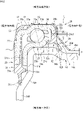
- FIG. 1 is a cross-sectional view of a strut-type suspension to which a thrust bearing according to a first embodiment is applied;
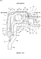
- FIG. 4 is a cross-sectional view of a thrust bearing;
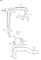
- FIG. 5 is a cross-sectional view of a thrust bearing according to a second embodiment;
- 1 is a cross-sectional view of a conventional thrust bearing;
- FIG. It is explanatory drawing which shows the assembly process of a thrust bearing.
- the thrust bearing of the present embodiment includes a first annular bearing ring, a second annular bearing ring axially facing the first bearing ring, and a combination of the first bearing ring and the second bearing ring. a plurality of rolling elements arranged to be able to roll therebetween; and an outer side provided on the second bearing ring and sealing a space between the first bearing ring and the second bearing ring on the outer peripheral side thereof. A seal and a cover covering the outer seal from the outside in the radial direction are provided.
- the cover can prevent muddy water or the like from reaching the outer seal. Therefore, the effect of preventing muddy water or the like from entering can be enhanced without increasing the rigidity of the outer seal.
- the cover has a support portion that is in contact with the outer peripheral surface of the outer seal and presses the outer seal from the outside in the radial direction.
- the outer seal can be prevented from elastically deforming radially outward by using the cover, and the straining force of the outer seal to the first bearing ring can be increased.
- the cover has an extending portion extending from the second bearing ring side toward the mounting member to which the first bearing ring is assembled.
- a space is formed between the extension portion, the outer seal, and the mounting member.
- FIG. 1 is a cross-sectional view of a strut-type suspension to which a thrust bearing according to the first embodiment is applied.
- a strut-type suspension 10 has a strut 11, an upper support 12, a coil spring 13, an upper spring seat 14, a thrust bearing 20, and the like.
- the strut 11 incorporates a shock absorber and generates a damping force by the viscous resistance of the hydraulic fluid.
- the upper support 12 is attached to the vehicle body 15 and supports the upper end of the strut 11 .
- a coil spring 13 is arranged on the outer periphery of the strut 11 and absorbs the impact from the road surface.
- the upper spring seat 14 receives and supports the upper end of the coil spring 13 .
- a lower end of the coil spring 13 is supported by a lower spring seat (not shown) provided on the lower side of the strut 11 .
- FIG. 2 is a cross-sectional view of a thrust bearing.
- the thrust bearing 20 has a first bearing ring 21 , a second bearing ring 22 , a plurality of rolling elements 23 , a retainer 24 , a seal 25 and a cover 26 .
- the axial center of the thrust bearing 20 coincides with the kingpin axis C, which is the central steering axis of the wheel.
- the kingpin axis C is tilted with respect to the vertical direction, and the axial center of the thrust bearing 20 is similarly tilted with respect to the vertical direction.
- the axial center of the thrust bearing 20 is also denoted by the same symbol "C" as the kingpin axis.
- the direction perpendicular to the axial center C of the thrust bearing 20 is called the radial direction.
- the first bearing ring 21 is attached to the upper surface side of the upper spring seat 14 . Therefore, the upper spring seat 14 constitutes a mounting member for the first bearing ring 21 .
- the first bearing ring 21 is formed in an annular shape by pressing a sheet metal such as a stainless steel plate.
- the first bearing ring 21 has a first raceway portion 21a that constitutes the raceway of the rolling elements 23 .
- the cross-sectional shape of the first raceway portion 21 a is curved in an arc shape substantially along the outer peripheral surface of the ball, which is the rolling element 23 .
- the first raceway portion 21 a contacts the rolling elements 23 with a contact angle inclined with respect to the axial center C of the thrust bearing 20 .
- the first bearing ring 21 further has a first annular portion 21b and a first cylindrical portion 21c.
- the first annular portion 21b is formed in an annular shape having flat surfaces (upper and lower surfaces) along a direction orthogonal to the axis C (see FIG. 1), and extends radially inward from the inner peripheral portion of the first raceway portion 21a. extends to
- the first cylindrical portion 21c is formed in a cylindrical shape having an outer peripheral surface and an inner peripheral surface centering on the axis C, and is bent from the inner peripheral portion of the first annular portion 21b to one axial side (lower side). extended.
- the upper spring seat 14 to which the first bearing ring 21 is attached has a fourth annular portion 14a, a first inclined portion 14b, and a fifth annular portion 14c.
- the fourth annular portion 14a is formed in an annular shape having flat surfaces (an upper surface and a lower surface) extending in a direction orthogonal to the axis C, and is superimposed on the lower side of the first annular portion 21b of the first bearing ring 21.
- the first inclined portion 14b is formed in a conical shape having an outer peripheral surface and an inner peripheral surface that are inclined with respect to the axis C, and extends diagonally outward and downward in the radial direction from the outer peripheral portion of the fourth annular portion 14a.
- the fifth annular portion 14c is formed in an annular shape having flat surfaces (upper and lower surfaces) along the direction perpendicular to the axis C, and extends radially outward from the outer peripheral portion of the first inclined portion 14b.
- the first inclined portion 14b may be omitted.
- the fourth annular portion 14a is further extended radially outward, and the fourth annular portion 14a is provided with a first outer lip, which will be described later.
- a gap t is formed between the fourth annular portion 14a and the tip (seventh annular portion 26e) of the cover 26, which will be described later.
- the upper spring seat 14 further has a fourth cylindrical portion 14d, a second inclined portion 14e, and a fifth cylindrical portion 14f.
- the fourth cylindrical portion 14d is formed in a cylindrical shape having an outer peripheral surface and an inner peripheral surface centering on the axis C, and is bent from the inner peripheral portion of the fourth annular portion 14a to one axial side (lower side). extended.
- the second inclined portion 14e is formed in a conical shape having an outer peripheral surface and an inner peripheral surface that are inclined with respect to the axis C, and extends obliquely to one axial side and radially inward from the lower end portion of the fourth cylindrical portion 14d.
- the fifth cylindrical portion 14f is formed in a cylindrical shape having an outer peripheral surface and an inner peripheral surface centering on the axis C, and extends axially to one side from the lower end portion of the second inclined portion 14e.
- the first cylindrical portion 21c of the first bearing ring 21 is fitted to the inner peripheral surface of the fourth cylindrical portion 14d.
- the second inclined portion 14e may be omitted.
- the fourth cylindrical portion 14d is further extended to one side in the axial direction, and the inner seal 31, which will be described later, is attached to the fourth cylindrical portion 14d.
- the inner lip 31b will come into contact.
- the second bearing ring 22 is attached to the lower surface side of the upper support 12 .
- the second bearing ring 22 is formed in an annular shape by pressing a sheet metal such as a stainless steel plate.
- the second bearing ring 22 and the first bearing ring 21 are arranged to face each other in the axial direction.
- the second bearing ring 22 has a second raceway portion 22a forming the raceway of the rolling elements 23 .
- the cross-sectional shape of the second raceway portion 22 a is curved in an arc shape substantially along the outer peripheral surface of the rolling element 23 .
- the second raceway portion 22 a contacts the rolling elements 23 with a contact angle that is inclined with respect to the axial center C of the thrust bearing 20 .
- the thrust bearing 20 can receive not only axial load but also radial load. It can be used for receiving purposes. However, the first bearing ring 21 and the second bearing ring 22 may be in contact with the rolling elements 23 without a contact angle, and the thrust bearing 20 is used for applications that receive only axial loads. may be
- the second bearing ring 22 further has a second annular portion 22b, a second cylindrical portion 22c, a third annular portion 22d, and a third cylindrical portion 22e.
- the second annular portion 22b is formed in an annular shape having flat surfaces (upper and lower surfaces) along a direction perpendicular to the axis C (see FIG. 1), and extends radially inward from the inner peripheral portion of the second raceway portion 22a. extends to
- the second cylindrical portion 22c is formed in a cylindrical shape having an outer peripheral surface and an inner peripheral surface centering on the axis C, and extends axially to one side (lower side) from the inner peripheral portion of the second annular portion 22b. .
- the second cylindrical portion 22c is arranged radially inward of the first cylindrical portion 21c with a space therebetween.
- the third annular portion 22d is formed in an annular shape having flat surfaces (upper surface and lower surface) along the direction orthogonal to the axis C, and extends radially outward from the outer peripheral portion of the second raceway portion 22a.
- the third cylindrical portion 22e is formed in a cylindrical shape having an outer peripheral surface and an inner peripheral surface around the axis C, and extends axially to one side (lower side) from the outer peripheral portion of the third annular portion 22d.
- the seal 25 seals the space formed between the first bearing ring 21 and the second bearing ring 22 .
- a lubricant such as grease is enclosed in this space.
- the seal 25 is made of an elastic material such as rubber that is vulcanized and bonded to the second bearing ring 22 .
- the second bearing ring 22 also functions as a core bar of the seal 25 .
- Rubber materials with good oil resistance include nitrile rubber (NBR), hydrogenated nitrile rubber (HNBR), acrylic rubber (ACM), ethylene-acrylic rubber (AEM), fluororubber ( FKM, FPM), silicone rubber (VQM), etc., one or two or more rubbers can be appropriately blended and used.
- NBR nitrile rubber
- HNBR hydrogenated nitrile rubber
- ACM acrylic rubber
- AEM ethylene-acrylic rubber
- FKM, FPM fluororubber
- VQM silicone rubber
- the seal 25 has an inner seal 31 , an outer seal 32 and a covering portion 33 .
- the inner seal 31 seals the space between the first bearing ring 21 and the second bearing ring 22 radially inward of the rolling elements 23 .
- the inner seal 31 is provided at the lower end of the second cylindrical portion 22c of the second bearing ring 22. As shown in FIG.
- the inner seal 31 has a base portion 31a extending downward from the lower end of the second cylindrical portion 22c and an inner lip 31b extending further downward from the base portion 31a.
- the inner lip 31b contacts the upper spring seat 14. Specifically, the inner lip 31b contacts the second inclined portion 14e. 2, the inner lip 31b in a free state (unloaded state) that is not in contact with the upper spring seat 14 is indicated by a chain double-dashed line. A solid line indicates the lip 31b.
- the inner seal 31 further has a ridge portion 31c protruding radially outward from the base portion 31a. A gap is formed between the tip of the projection 31c and the fourth cylindrical portion 14d of the upper spring seat 14. As shown in FIG.
- the outer seal 32 seals the space between the first bearing ring 21 and the second bearing ring 22 radially outside the rolling elements 23 .
- the outer seal 32 is provided at the lower end of the third cylindrical portion 22e of the second bearing ring 22.
- Outer seal 32 has a base 32a, a first outer lip 32b and a second outer lip 32c.
- the base portion 32 a extends downward from the lower end of the third cylindrical portion 22 e of the second bearing ring 22 .
- the first outer lip 32b extends further downward from the lower end of the base 32a.
- the first outer lip 32b contacts the upper spring seat 14. As shown in FIG. Specifically, the first outer lip 32 b contacts the first inclined portion 14 b of the upper spring seat 14 .
- the second outer lip 32c extends radially inward from the lower end of the base 32a.
- the second outer lip 32 c contacts the first bearing ring 21 .
- the second outer lip 32 c contacts the outer surface of the first raceway portion 21 a of the first bearing ring 21 .
- first and second outer lips 32b and 32c in a free state are indicated by chain double-dashed lines, and the first outer lip 32b and 32c elastically deformed from the free state by coming into contact with the upper spring seat 14 or the first bearing ring 21.
- the second outer lips 32b, 32c are shown in solid lines.
- the covering portion 33 covers the surface of the second bearing ring 22 and connects the inner seal 31 and the outer seal 32 .
- the covering portion 33 includes the outer peripheral surface and the inner peripheral surface of the second cylindrical portion 22c of the second bearing ring 22, the upper surfaces of the second annular portion 22b, the second raceway portion 22a, and the third annular portion 22d, and , the inner and outer peripheral surfaces of the third cylindrical portion 22e.
- the cover 26 is attached to the second bearing ring 22 and covers the outer seal 32 from the radial outside.
- the cover 26 is formed by pressing sheet metal such as stainless steel plate.
- the cover 26 has a sixth annular portion 26a, a curved portion 26b, a sixth cylindrical portion 26c, a third inclined portion 26d, and a seventh annular portion 26e.
- the sixth annular portion 26a is on the other axial side (upper side) of the third annular portion 22d of the second bearing ring 22, substantially on the other axial side of the covering portion 33 of the seal 25 that covers the third annular portion 22d ( above).
- the curved portion 26b is curved in an arc shape from the outer peripheral portion of the sixth annular portion 26a toward one side (lower side) in the axial direction.
- the curved portion 26b overlaps the outer peripheral surface of the boundary portion between the third annular portion 22d and the third cylindrical portion 22e of the second bearing ring 22, substantially the outer peripheral surface of the covering portion 33 that covers the outer peripheral surface. .
- the sixth cylindrical portion 26c extends in the same direction from the end portion on one axial side (lower side) of the curved portion 26b.
- the sixth cylindrical portion 26c is fitted to the outer peripheral surface of the third cylindrical portion 22e of the second bearing ring 22, substantially to the outer peripheral surface of the covering portion 33 of the seal 25 that covers the third cylindrical portion 22e.
- the sixth cylindrical portion 26c extends axially to one side (lower side) than the third cylindrical portion 22e and contacts the outer peripheral surface of the base portion 32a of the outer seal 32.
- a portion 26c1 of the sixth cylindrical portion 26c that contacts the outer peripheral surface of the base portion 32a of the outer seal 32 constitutes a "support portion” that presses and supports the base portion 32a from the outside in the radial direction.
- the third inclined portion 26d obliquely extends from the end portion of the sixth cylindrical portion 26c on one axial side to the one axial side and radially outward.
- the third inclined portion 26d extends linearly and has a substantially conical shape.
- the third inclined portion 26d constitutes an "extended portion" extending from the second bearing ring 22 side toward the upper spring seat 14 side.
- the extended portion is not limited to a shape extending linearly, and may be curved so as to bulge radially outward or radially inward. An example in which the extending portion is curved radially outward will be described later as a second embodiment.
- the distance W between the third inclined portion 26d and the outer seal 32 is from the second bearing ring 22 side to the upper spring seat 14 side (axial direction).
- the third inclined portion 26d is formed so as to gradually widen toward the one side).
- a space S surrounded by the third inclined portion 26d, the outer seal 32, and the upper spring seat 14 is formed.
- the space S has a cross-sectional area that does not contact the third inclined portion 26d of the cover 26 even if the outer seal 32 is elastically deformed radially outward when the strut suspension 10 is in use.
- the seventh annular portion 26e of the cover 26 extends radially outward from the outer peripheral portion of the third inclined portion 26d.
- the seventh annular portion 26 e is arranged substantially parallel to the fifth annular portion 14 c of the upper spring seat 14 .
- a gap t is formed between the seventh annular portion 26e and the fifth annular portion 14c. This gap t is preferably set to 0.5 mm to 1.5 mm, more preferably about 1 mm.
- the seventh annular portion 26e and the fifth annular portion 14c may be in contact with each other.
- the seventh annular portion 26e may be omitted and a gap t may be formed between the extending portion 26d and the fifth annular portion 14c, or the extending portion 26d and the fifth annular portion 14c may be brought into contact with each other.
- the cover 26 may directly overlap the third annular portion 22d and the third cylindrical portion 22e of the second bearing ring 22 without the covering portion 33 interposed therebetween.
- the thrust bearing 20 of the first embodiment includes a ring-shaped first bearing ring 21, a second bearing ring 22 axially facing the first bearing ring 21, and the first bearing ring 21 and the second bearing ring 22. a plurality of rolling elements 23 arranged to be able to roll therebetween; It has an outer seal 32 that seals a space, and a cover 26 that covers the outer seal 32 from the outside in the radial direction.
- the cover 26 can prevent muddy water or the like from reaching the outer seal 32 . Therefore, by increasing the rigidity of the outer seal 32, it is possible to prevent water such as muddy water and foreign matter from entering the thrust bearing 20 without increasing the straining force of the second outer lip 32c against the first bearing ring 21.
- the second raceway ring 21 (121) is provided with the second raceway ring 21 (121) as described with reference to FIG. 5, for example.
- the ring 22 (122) it is possible to suppress the occurrence of an assembly failure in which the second outer lip 32c (132c) of the outer seal 32 (132) remains inverted.
- the cover 26 has a support portion 26c1 that contacts the outer peripheral surface of the outer seal 32 and presses the outer seal 32 from the outside in the radial direction. Therefore, even if the rigidity of the outer seal 32 is not increased, elastic deformation of the outer seal 32 to the outside in the radial direction is suppressed, the straining force of the second outer lip 32c against the first bearing ring 21 is increased, and the penetration of muddy water or the like is prevented. The prevention effect can be further enhanced. Moreover, by attaching the cover 26 to the second bearing ring 22 after the thrust bearing 20 is assembled, it is possible to suppress the occurrence of an assembly failure in which the second outer lip 32c remains inverted.
- the cover 26 has an extending portion 26d extending from the first bearing ring 21 side toward the upper spring seat 14. As shown in FIG. Therefore, muddy water splashed up from the outside can be blocked by the extended portion 26 d and can be effectively suppressed from reaching the outer seal 32 .
- a space S is formed between the extending portion 26d, the outer seal 32 and the upper spring seat 14. If this space S were not provided, foreign matter such as mud would easily clog between the outer seal 32 and the extending portion 26d, and the first outer lip 32b would be strongly pressed against the upper spring seat 14, causing the thrust bearing 20 to resist rotation. may increase.
- the space S is formed between the outer seal 32, the extended portion 26d, and the upper spring seat 14, even if muddy water or the like enters, the muddy water or the like can be moved within the space S. It is possible to suppress clogging of mud or the like between the outer seal 32 and the extended portion 26d.
- the cover 26 has a seventh annular portion 26e arranged substantially parallel to the upper spring seat 14 at the tip of the extended portion 26d, and a gap t is formed between the seventh annular portion 26e and the upper spring seat 14. there is By providing the seventh annular portion 26e extending further radially outward from the extending portion 26d in this way, the gap t can be formed to be long in the radial direction, and the arrival of muddy water or the like to the outer seal 32 can be further suppressed. can be done. Further, since the seventh annular portion 26e is formed in a flat shape substantially parallel to the upper spring seat 14, the gap t between the seventh annular portion 26e and the upper spring seat 14 is maintained narrow. Intrusion of muddy water into the gap t is further suppressed.
- the gap t is formed between the seventh annular portion 26e of the cover 26 and the upper spring seat 14, even if muddy water enters the cover 26, it can be easily discharged.
- the axial center C of the thrust bearing 20 is inclined with respect to the vertical direction as shown in FIG. This increases the possibility that muddy water or the like will pass through the outer seal 32 and enter between the first bearing ring 21 and the second bearing ring 22 . Therefore, forming the gap t is more effective.
- the portion of the space S connected to the gap t has a cross-sectional area (and volume) that is larger in the axial direction than the gap t. Therefore, muddy water or the like that has entered through the gap t enters the expanded space S, and can easily move in the space S. Therefore, clogging of foreign matter such as mud in the space S can be further suppressed.
- the cover 26 has a sixth annular portion 26a that overlaps the upper surface of the third annular portion 22d of the second bearing ring 22 (substantially, the covering portion 33 that covers the third annular portion 22d).
- the sixth annular portion 26a enables the cover 26 to be attached to the second bearing ring 22 in a stable posture. If the cover 26 does not have the sixth annular portion 26a, the cover 26 is attached to the second bearing ring 22 only by the sixth cylindrical portion 26c or by the sixth cylindrical portion 26c and the curved portion 26b.
- the sixth cylindrical portion 26c and the curved portion 26b are substantially overlapped with the covering portion 33 of the seal 25, but since the covering portion 33 is an elastic body, it is not formed with such strict dimensional accuracy.
- the posture of the cover 26 overlaid on the covering portion 33 becomes unstable, and the dimension of the gap t between the upper spring seat 14 and the cover 26 and the volume of the space S tend to vary.
- the cover 26 is provided with the sixth annular portion 26a, and the sixth annular portion 26a overlaps the second bearing ring 22 (and the covering portion 33 covering it), so that the cover 26 is stabilized. It can be attached to the second bearing ring 22 in a posture.
- FIG. 3 is a cross-sectional view of a thrust bearing according to the second embodiment.
- the thrust bearing according to the second embodiment differs from the first embodiment in the structure of the cover 26 .
- the cover 26 of this embodiment has a sixth annular portion 26a, a curved portion 26b, a sixth cylindrical portion 26c, and a seventh annular portion 26e, which are substantially the same as those of the first embodiment. 2, the shape of the extending portion illustrated by the third inclined portion 26d is different.
- the extending portion 26f of this embodiment has an eighth annular portion 26f1, a second curved portion 26f2, and a seventh cylindrical portion 26f3.
- the eighth annular portion 26f1 is formed in an annular shape having flat surfaces (upper and lower surfaces) along a direction orthogonal to the axis C (see FIG. 1), and is located on one axial side (lower side) of the sixth cylindrical portion 26c. ) extending radially outward from the end of the .
- the second curved portion 26f2 curves in an arc shape from the outer peripheral portion of the eighth annular portion 26f1 toward one side (lower side) in the axial direction.
- the seventh cylindrical portion 26f3 extends in the same direction from the end portion on one axial side (lower side) of the second curved portion 26f2.
- a seventh annular portion 26e is connected to the lower end of the seventh cylindrical portion 26f3.
- ordinal numbers such as “first” and “second” attached to the annular portion, cylindrical portion, inclined portion, etc., which are the constituent elements of the first and second bearing rings and the upper spring seat 14 described above, distinguish each other.
- the number itself has no meaning. Therefore, the ordinal numbers may be omitted or replaced with other ordinal numbers.
Landscapes
- Engineering & Computer Science (AREA)
- General Engineering & Computer Science (AREA)
- Mechanical Engineering (AREA)
- Sealing Of Bearings (AREA)
- Rolling Contact Bearings (AREA)
- Sealing With Elastic Sealing Lips (AREA)
- Sealing Devices (AREA)
Priority Applications (5)
| Application Number | Priority Date | Filing Date | Title |
|---|---|---|---|
| PCT/JP2021/017558 WO2022234667A1 (ja) | 2021-05-07 | 2021-05-07 | スラスト軸受 |
| CN202180095385.2A CN116964344A (zh) | 2021-05-07 | 2021-05-07 | 推力轴承 |
| US18/287,838 US12553473B2 (en) | 2021-05-07 | 2021-05-07 | Thrust bearing |
| DE112021007619.1T DE112021007619T5 (de) | 2021-05-07 | 2021-05-07 | Axiallager |
| JP2023518595A JP7498859B2 (ja) | 2021-05-07 | 2021-05-07 | スラスト軸受 |
Applications Claiming Priority (1)
| Application Number | Priority Date | Filing Date | Title |
|---|---|---|---|
| PCT/JP2021/017558 WO2022234667A1 (ja) | 2021-05-07 | 2021-05-07 | スラスト軸受 |
Publications (1)
| Publication Number | Publication Date |
|---|---|
| WO2022234667A1 true WO2022234667A1 (ja) | 2022-11-10 |
Family
ID=83932706
Family Applications (1)
| Application Number | Title | Priority Date | Filing Date |
|---|---|---|---|
| PCT/JP2021/017558 Ceased WO2022234667A1 (ja) | 2021-05-07 | 2021-05-07 | スラスト軸受 |
Country Status (5)
| Country | Link |
|---|---|
| US (1) | US12553473B2 (https=) |
| JP (1) | JP7498859B2 (https=) |
| CN (1) | CN116964344A (https=) |
| DE (1) | DE112021007619T5 (https=) |
| WO (1) | WO2022234667A1 (https=) |
Citations (6)
| Publication number | Priority date | Publication date | Assignee | Title |
|---|---|---|---|---|
| JPS58124825A (ja) * | 1982-01-15 | 1983-07-25 | ゼネラル・モ−タ−ズ・コ−ポレ−シヨン | 密封スラスト軸受組立体 |
| JPS62134922U (https=) * | 1986-02-19 | 1987-08-25 | ||
| JPS62179424U (https=) * | 1986-05-06 | 1987-11-14 | ||
| JPH0777220A (ja) * | 1993-09-10 | 1995-03-20 | Koyo Seiko Co Ltd | 密封型スラスト玉軸受 |
| JPH07332378A (ja) * | 1994-06-03 | 1995-12-22 | Nippon Seiko Kk | 密封型スラスト軸受 |
| WO2019119320A1 (en) * | 2017-12-20 | 2019-06-27 | Schaeffler Technologies AG & Co. KG | Strut bearing |
Family Cites Families (9)
| Publication number | Priority date | Publication date | Assignee | Title |
|---|---|---|---|---|
| FR2850905B1 (fr) * | 2003-02-10 | 2006-06-23 | Skf Ab | Dispositif de butee de suspension |
| FR2910944B1 (fr) * | 2006-12-29 | 2009-02-20 | Snr Roulements Sa | Butee de suspension a roulement, cage de roulement et garniture d'etancheite |
| EP2336589B1 (en) | 2008-10-01 | 2014-09-10 | JTEKT Corporation | Clutch release bearing device |
| FR2961439A1 (fr) | 2010-06-16 | 2011-12-23 | Skf Ab | Dispositif de butee de suspension |
| JP6439758B2 (ja) * | 2016-07-25 | 2018-12-19 | 株式会社ジェイテクト | 密封型スラスト玉軸受 |
| DE112018007309B4 (de) * | 2018-03-20 | 2023-03-16 | Schaeffler Technologies AG & Co. KG | Flachlager |
| DE102018217666A1 (de) * | 2018-10-16 | 2020-04-16 | Aktiebolaget Skf | Aufhängungsaxiallagervorrichtung |
| EP3964371B1 (en) * | 2019-04-28 | 2024-07-17 | Schaeffler Technologies AG & Co. KG | Spring damper bearing assembly |
| CN111720446B (zh) * | 2020-05-26 | 2022-06-21 | 上海百信轴承有限公司 | 一种密封型推力球轴承 |
-
2021
- 2021-05-07 JP JP2023518595A patent/JP7498859B2/ja active Active
- 2021-05-07 CN CN202180095385.2A patent/CN116964344A/zh active Pending
- 2021-05-07 US US18/287,838 patent/US12553473B2/en active Active
- 2021-05-07 DE DE112021007619.1T patent/DE112021007619T5/de active Pending
- 2021-05-07 WO PCT/JP2021/017558 patent/WO2022234667A1/ja not_active Ceased
Patent Citations (6)
| Publication number | Priority date | Publication date | Assignee | Title |
|---|---|---|---|---|
| JPS58124825A (ja) * | 1982-01-15 | 1983-07-25 | ゼネラル・モ−タ−ズ・コ−ポレ−シヨン | 密封スラスト軸受組立体 |
| JPS62134922U (https=) * | 1986-02-19 | 1987-08-25 | ||
| JPS62179424U (https=) * | 1986-05-06 | 1987-11-14 | ||
| JPH0777220A (ja) * | 1993-09-10 | 1995-03-20 | Koyo Seiko Co Ltd | 密封型スラスト玉軸受 |
| JPH07332378A (ja) * | 1994-06-03 | 1995-12-22 | Nippon Seiko Kk | 密封型スラスト軸受 |
| WO2019119320A1 (en) * | 2017-12-20 | 2019-06-27 | Schaeffler Technologies AG & Co. KG | Strut bearing |
Also Published As
| Publication number | Publication date |
|---|---|
| US20240183404A1 (en) | 2024-06-06 |
| CN116964344A (zh) | 2023-10-27 |
| JP7498859B2 (ja) | 2024-06-12 |
| JPWO2022234667A1 (https=) | 2022-11-10 |
| DE112021007619T5 (de) | 2024-02-29 |
| US12553473B2 (en) | 2026-02-17 |
Similar Documents
| Publication | Publication Date | Title |
|---|---|---|
| US20130127119A1 (en) | Sealing assembly for rolling bearings | |
| JP6439758B2 (ja) | 密封型スラスト玉軸受 | |
| JP6771739B2 (ja) | 密封構造 | |
| CN112901663B (zh) | 密封装置 | |
| KR20090021164A (ko) | 슬라이드 베어링 | |
| CN1965186A (zh) | 密封装置 | |
| JP2008128396A (ja) | 密封装置 | |
| CN110088492A (zh) | 密封装置 | |
| JP2013242033A (ja) | 転がり軸受 | |
| CN105465207B (zh) | 万向节 | |
| JP5196092B2 (ja) | 密封装置 | |
| CN110446870B (zh) | 车轮用轴承装置 | |
| JP7498859B2 (ja) | スラスト軸受 | |
| JP7046514B2 (ja) | 密封装置 | |
| JP6955981B2 (ja) | ダストシール | |
| JP6985881B2 (ja) | 車輪用軸受装置 | |
| CN105697540B (zh) | 包括密封法兰的滚动轴承 | |
| JP7273963B2 (ja) | 密封装置、密封構造および密封構造の固定方法 | |
| JP2013060975A (ja) | 密封装置及び転がり軸受装置 | |
| JP2019157917A (ja) | 密封構造及び当該密封構造を有する転がり軸受装置 | |
| JP4417190B2 (ja) | 密封装置 | |
| JP2013072463A (ja) | 車輪用軸受装置 | |
| JP7023681B2 (ja) | ハブユニット用密封装置 | |
| JP4743402B2 (ja) | 密封装置 | |
| JP2006002788A (ja) | 車輪軸受用シール |
Legal Events
| Date | Code | Title | Description |
|---|---|---|---|
| 121 | Ep: the epo has been informed by wipo that ep was designated in this application |
Ref document number: 21939590 Country of ref document: EP Kind code of ref document: A1 |
|
| WWE | Wipo information: entry into national phase |
Ref document number: 202180095385.2 Country of ref document: CN |
|
| WWE | Wipo information: entry into national phase |
Ref document number: 18287838 Country of ref document: US |
|
| WWE | Wipo information: entry into national phase |
Ref document number: 2023518595 Country of ref document: JP |
|
| WWE | Wipo information: entry into national phase |
Ref document number: 112021007619 Country of ref document: DE |
|
| 122 | Ep: pct application non-entry in european phase |
Ref document number: 21939590 Country of ref document: EP Kind code of ref document: A1 |
|
| WWG | Wipo information: grant in national office |
Ref document number: 18287838 Country of ref document: US |