WO2022230677A1 - アクチュエータ、ポンプ、アクチュエータの製造方法 - Google Patents
アクチュエータ、ポンプ、アクチュエータの製造方法 Download PDFInfo
- Publication number
- WO2022230677A1 WO2022230677A1 PCT/JP2022/017808 JP2022017808W WO2022230677A1 WO 2022230677 A1 WO2022230677 A1 WO 2022230677A1 JP 2022017808 W JP2022017808 W JP 2022017808W WO 2022230677 A1 WO2022230677 A1 WO 2022230677A1
- Authority
- WO
- WIPO (PCT)
- Prior art keywords
- frame
- outer edge
- convex portion
- shape
- plan
- Prior art date
- Legal status (The legal status is an assumption and is not a legal conclusion. Google has not performed a legal analysis and makes no representation as to the accuracy of the status listed.)
- Ceased
Links
Images


Classifications
-
- F—MECHANICAL ENGINEERING; LIGHTING; HEATING; WEAPONS; BLASTING
- F04—POSITIVE - DISPLACEMENT MACHINES FOR LIQUIDS; PUMPS FOR LIQUIDS OR ELASTIC FLUIDS
- F04B—POSITIVE-DISPLACEMENT MACHINES FOR LIQUIDS; PUMPS
- F04B43/00—Machines, pumps, or pumping installations having flexible working members
- F04B43/02—Machines, pumps, or pumping installations having flexible working members having plate-like flexible members, e.g. diaphragms
- F04B43/04—Pumps having electric drive
- F04B43/043—Micropumps
- F04B43/046—Micropumps with piezoelectric drive
-
- F—MECHANICAL ENGINEERING; LIGHTING; HEATING; WEAPONS; BLASTING
- F04—POSITIVE - DISPLACEMENT MACHINES FOR LIQUIDS; PUMPS FOR LIQUIDS OR ELASTIC FLUIDS
- F04B—POSITIVE-DISPLACEMENT MACHINES FOR LIQUIDS; PUMPS
- F04B43/00—Machines, pumps, or pumping installations having flexible working members
- F04B43/02—Machines, pumps, or pumping installations having flexible working members having plate-like flexible members, e.g. diaphragms
- F04B43/04—Pumps having electric drive
-
- F—MECHANICAL ENGINEERING; LIGHTING; HEATING; WEAPONS; BLASTING
- F04—POSITIVE - DISPLACEMENT MACHINES FOR LIQUIDS; PUMPS FOR LIQUIDS OR ELASTIC FLUIDS
- F04B—POSITIVE-DISPLACEMENT MACHINES FOR LIQUIDS; PUMPS
- F04B45/00—Pumps or pumping installations having flexible working members and specially adapted for elastic fluids
- F04B45/04—Pumps or pumping installations having flexible working members and specially adapted for elastic fluids having plate-like flexible members, e.g. diaphragms
- F04B45/047—Pumps having electric drive
-
- H—ELECTRICITY
- H10—SEMICONDUCTOR DEVICES; ELECTRIC SOLID-STATE DEVICES NOT OTHERWISE PROVIDED FOR
- H10N—ELECTRIC SOLID-STATE DEVICES NOT OTHERWISE PROVIDED FOR
- H10N30/00—Piezoelectric or electrostrictive devices
- H10N30/01—Manufacture or treatment
- H10N30/02—Forming enclosures or casings
-
- H—ELECTRICITY
- H10—SEMICONDUCTOR DEVICES; ELECTRIC SOLID-STATE DEVICES NOT OTHERWISE PROVIDED FOR
- H10N—ELECTRIC SOLID-STATE DEVICES NOT OTHERWISE PROVIDED FOR
- H10N30/00—Piezoelectric or electrostrictive devices
- H10N30/20—Piezoelectric or electrostrictive devices with electrical input and mechanical output, e.g. functioning as actuators or vibrators
- H10N30/204—Piezoelectric or electrostrictive devices with electrical input and mechanical output, e.g. functioning as actuators or vibrators using bending displacement, e.g. unimorph, bimorph or multimorph cantilever or membrane benders
- H10N30/2047—Membrane type
-
- H—ELECTRICITY
- H10—SEMICONDUCTOR DEVICES; ELECTRIC SOLID-STATE DEVICES NOT OTHERWISE PROVIDED FOR
- H10N—ELECTRIC SOLID-STATE DEVICES NOT OTHERWISE PROVIDED FOR
- H10N30/00—Piezoelectric or electrostrictive devices
- H10N30/80—Constructional details
- H10N30/88—Mounts; Supports; Enclosures; Casings
Definitions
- the present invention relates to an actuator whose housing is assembled using an adhesive.
- Patent Document 1 describes a fluid pump.
- a fluid pump described in Patent Document 1 includes a diaphragm, a diaphragm support frame, a connecting portion, a piezoelectric element, a spacer, and a lid portion.
- the diaphragm is a disc.
- the diaphragm support frame has a shape surrounding the outer circumference of the diaphragm.
- the diaphragm is held vibratably with respect to the diaphragm support frame using the connecting portion.
- a piezoelectric element is attached to the diaphragm.
- the lid portion is arranged to face the plate member composed of the diaphragm, the connecting portion, and the diaphragm support frame.
- a spacer is arranged between the plate member and the lid.
- the spacer is frame-shaped with a hollow portion and is connected to the diaphragm support frame and the lid portion.
- the outer shape of the lid, spacer, and diaphragm support frame is the same, and these are adhered to each other with an adhesive, for example.
- the adhesive may not be able to sufficiently adhere to the members to be adhered due to unnecessarily overflowing the adhesive to the outside, etc., and reliability may be lowered.
- reliability is likely to deteriorate due to deterioration in adhesiveness.
- an object of the present invention is to improve the adhesiveness of each constituent member and realize a highly reliable device.
- the actuator of this invention includes a vibrating member, a frame, and an adhesive.
- the vibrating member has a first principal surface and a second principal surface, and a piezoelectric element is attached to at least one of the first principal surface and the second principal surface.
- the vibrating member has a plate-like shape, is larger than the piezoelectric element in plan view, and has an outer edge that is not in contact with the piezoelectric element.
- the frame body has an outer edge shape smaller than that of the vibrating member.
- the adhesive adheres the first main surface or the second main surface of the outer edge of the vibrating member to the frame. In plan view, the outer edge shape of the frame is smaller than the outer edge shape of the vibrating member.
- the frame has a projection that partially protrudes outward from the outer edge.
- the adhesive adheres to the protrusions as well, the adhesive area is larger than when there are no protrusions.
- the adhesiveness of each constituent member is improved and high reliability is achieved.
- FIG. 1 is an exploded perspective view of a pump according to a first embodiment of the present invention
- FIG. FIG. 2(A) is a plan view of the pump according to the first embodiment of the present invention
- FIG. 2(B) is a cross-sectional view taken along the line AA
- 3A is a plan view of the frame
- FIGS. 3B, 3C, 3D, and 3E are side views of the frame.
- 4(A) and 4(B) are partial enlarged perspective views showing an example of the bonding state between the frame and the vibrating member.
- FIG. 5 is an image diagram of cutting out a frame.
- FIGS. 6A, 6B, 6C, and 6D are plan views showing derivative examples of the frame.
- FIG. 1 is an exploded perspective view of a pump according to a first embodiment of the present invention
- FIG. FIG. 2(A) is a plan view of the pump according to the first embodiment of the present invention
- FIG. 2(B) is a cross-sectional view taken along the line AA. 2A and 2B, illustration of electrode patterns is omitted.
- the shape of each component may be partially or wholly exaggerated in order to make the configuration of the fluid control device easier to understand.
- the pump 10 includes an actuator 11 and a housing 20.
- the components of the actuator 11 and the housing 20 partially overlap.
- the actuator 11 includes a vibrating member 21, a frame 23, a piezoelectric element 30, and electrode patterns 41 and 42.
- the housing 20 includes a vibrating member 21 , a lid member 22 and a frame 23 .
- the vibration member 21 is a flat plate having a main surface F211 and a main surface F212.
- the vibrating member 21 is formed, for example, by punching metal.
- the vibrating member 21 includes a main flat plate 211 , an outer edge portion 212 and a connecting portion 213 .
- the main flat plate 211 is circular in plan view.
- the outer edge portion 212 has an annular shape in plan view.
- the inner edge of outer edge 212 is circular and the outer edge is octagonal. In plan view, the inner end of the outer edge portion 212 is located outside the outer edge of the main flat plate 211 and away from the outer edge of the main flat plate 211 .
- the connecting portion 213 is arranged between the outer edge of the main flat plate 211 and the inner end of the outer edge portion 212 .
- a plurality of connecting portions 213 are arranged along the outer edge of the main flat plate 211 at intervals.
- the connecting portion 213 has a beam shape and connects the outer edge of the main flat plate 211 and the inner end of the outer edge portion 212 . With this configuration, the main flat plate 211 is held with respect to the outer edge portion 212 via the connecting portion 213 so as to be capable of bending vibration.
- a region between the main flat plate 211 and the outer edge portion 212 where the connecting portion 213 does not exist serves as an opening 214 formed in the vibrating member 21 .
- the piezoelectric element 30 is a disc and is made of a piezoelectric material.
- the piezoelectric element 30 is arranged in contact with the main surface F211 of the main flat plate 211 .
- the lid member 22 is octagonal in plan view.
- the outer shape of the lid member 22 in plan view is substantially the same as the outer shape of the outer edge portion 212 of the vibrating member 21 .
- the lid member 22 has an opening 220 .
- the opening 220 is formed substantially in the center of the lid member 22 in plan view.
- the opening 220 is smaller than the piezoelectric element 30 in plan view.
- the lid member 22 is formed, for example, by punching metal.
- the frame 23 has an annular shape in plan view and has a cylindrical internal space 230 .
- the inner peripheral edge of the frame 23 is circular, and the outer peripheral edge is octagonal.
- the frame 23 is formed, for example, by punching metal.
- the shape of the inner peripheral end of the frame 23 in plan view is substantially similar to the shape of the inner end of the outer edge portion 212 of the vibrating member 21 .
- the circle forming the inner peripheral end of the frame 23 is larger than the circle forming the inner peripheral end of the outer edge portion 212 .
- the shape (outer shape) of the outer peripheral end of the frame 23 in plan view is substantially similar to the shape (outer shape) of the outer peripheral end of the outer edge portion 212 of the vibrating member 21 .
- the outer shape of the frame 23 is smaller than the outer shape of the outer edge portion 212 of the vibrating member 21 .
- the outer shape of the lid member 22 is approximately 0.9 times or more and less than 1.0 times the outer shape of the outer edge portion 212 of the vibrating member 21 . Note that this magnification relationship is an example, and is not limited to this.
- the frame 23 overlaps the outer edge 212 of the vibrating member 21 .
- One end surface of frame 23 in the height direction (the direction orthogonal to the inner end surface and the outer end surface) is adhered to main surface F212 of outer edge portion 212 using adhesive 241 .
- frame 23 overlaps the lid member 22 in plan view.
- the other end surface of frame 23 in the height direction (the direction orthogonal to the inner end surface and the outer end surface) is adhered to cover member 22 using adhesive 242 .
- the housing 20 has an internal space 230 surrounded by the vibrating member 21 , lid member 22 and frame 23 .
- This internal space 230 functions as a pump chamber of the pump 10 .
- Internal space 230 communicates with the outside of housing 20 through opening 214 and opening 220 .
- the electrode pattern 41 includes an internal connection portion 411 and an external terminal 412 .
- the internal connection portion 411 of the electrode pattern 41 overlaps the piezoelectric element 30 in plan view, and the tip portion of the internal connection portion 411 contacts the surface of the piezoelectric element 30 opposite to the surface that contacts the vibration member 21 .
- the external terminal 412 protrudes outward from the outer edge portion 212 of the vibrating member 21 in plan view.
- the electrode pattern 42 has an internal connection portion 421 and an external terminal 422 .
- the internal connection portion 421 of the electrode pattern 42 overlaps the outer edge portion 212 in plan view and contacts the main surface F211 of the outer edge portion 212 .
- the external terminal 422 protrudes outward from the outer edge portion 212 of the vibrating member 21 in plan view.
- the actuator 11 and the pump 10 operate as follows.
- a driving voltage is applied to the piezoelectric element 30 through the electrode pattern 41 and the electrode pattern 42 . By this.
- the piezoelectric element 30 is distorted and the main plate 211 vibrates.
- the outer edge portion 212 is fixed by the frame 23.
- the main flat plate 211 is held by a connecting portion 213 so as to be able to vibrate. Therefore, in the vibrating member 21 , the main flat plate 211 vibrates while the outer edge portion 212 is substantially fixed by the frame 23 . Thereby, the function as the actuator 11 is realized.
- the frame body 23 specifically has the following configuration.
- 3A is a plan view of the frame
- FIGS. 3B, 3C, 3D, and 3E are side views of the frame.
- the frame 23 has an internal space 230 and a protrusion 239 .
- the outer shape of the frame 23 is octagonal except for the protrusions 239 .
- the frame 23 has a principal surface 231 , a principal surface 232 , a side surface 2331 , a side surface 2332 , a side surface 2333 , a side surface 2334 , a side surface 2341 , a side surface 2342 , a side surface 2343 , and a side surface 2344 .
- the main surface 231 and the main surface 232 are both end surfaces in the thickness direction of the frame 23 and face each other.
- the outer shape of the main surface 231 and the main surface 232 (excluding the convex portion 239) is octagonal.
- Side 2331 , side 2332 , side 2333 , side 2334 , side 2341 , side 2342 , side 2343 , and side 2344 are perpendicular to major surfaces 231 and 232 and are connected to outer edges of major surfaces 231 and 232 . do.
- the side surfaces 2331 and 2332 face each other, and the side surfaces 2333 and 2334 face each other.
- the side surfaces 2331 and 2332 and the side surfaces 2333 and 2334 are perpendicular to each other.
- the side surfaces 2341 and 2342 face each other, and the side surfaces 2343 and 2344 face each other.
- the side surfaces 2341 and 2342 and the side surfaces 2343 and 2344 are perpendicular to each other.
- the side 2341 connects the side 2331 and the side 2333 .
- the side surface 2341 is arranged so that the center side of the frame 23 forms an angle of 135° with respect to the side surfaces 2331 and 2333 .
- the side 2342 connects the side 2332 and the side 2334 .
- the side surface 2342 is arranged so that the angle formed by the center side of the frame 23 with respect to the side surface 2332 and the side surface 2334 is 135°.
- the side 2343 connects the side 2331 and the side 2334 .
- the side surface 2343 is arranged so that the center side of the frame 23 forms an angle of 135° with respect to the side surface 2331 and the side surface 2334 .
- the side 2344 connects the side 2332 and the side 2333 .
- the side surface 2344 is arranged so that the angle formed by the center side of the frame 23 with respect to the side surface 2332 and the side surface 2333 is 135°.
- the side surface 2331, the side surface 2332, the side surface 2333, and the side surface 2334 have the same length (same length in plan view).
- Side 2341, side 2342, side 2343, and side 2344 have the same length (same length in plan view).
- Side 2331 , side 2332 , side 2333 and side 2334 are longer than side 2341 , side 2342 , side 2343 and side 2344 .
- the frame 23 has a circular internal space 230 in plan view.
- the internal space 230 is a through hole penetrating the frame 23 from the main surface 231 to the main surface 232 .
- the center of the frame 23 and the center of the internal space 230 match. It should be noted that coincidence here includes the case where each center is slightly deviated due to a manufacturing error or the like.
- the thickness W233 on the center side from the side surfaces 2331, 2332, 2333, and 2334 is smaller than the thickness W234 on the center side from the side surfaces 2341, 2342, 2343, and 2344.
- the thickness W233 from the long side to the center is smaller than the thickness W234 from the short side to the center.
- the thickness from the side to the center is defined by the shortest distance between the side and the internal space 230 .
- the convex portion 239 protrudes outward from a side surface 2341 that is the outer edge of the frame 23 .
- the protrusion 239 has a semi-cylindrical shape and partially protrudes from the side surface 2341 . Partial here means partial in the circumferential direction of the side surface 2341 .
- the convex portion 239 is formed over the entire thickness direction of the frame 23 .
- the amount of protrusion of the convex portion 239 is approximately 5 ⁇ m when the distance from the center of the frame 23 to each side surface is approximately 30 ⁇ m.
- this dimension is an example and is not limited to this.
- the bonding area between the frame 23 and the outer edge portion 212 of the vibrating member 21 and the bonding area between the frame 23 and the lid member 22 are reduced by the comparison configuration without the convex portions 239 ( conventional configuration).
- FIGS. 4(A) and 4(B) are partial enlarged perspective views showing an example of the bonding state between the frame and the vibrating member.
- FIG. 4A shows the configuration of this embodiment
- FIG. 4B shows a comparative configuration.
- the contact area between the frame 23 and the outer edge 212 of the vibrating member 21 is increased by providing the convex portion 239, and the contact area between the frame 23 and the vibration member 21 is increased.
- the length of the outline that contacts the outer edge portion 212 of the vibrating member 21 also increases.
- the area where the frame 23 and the outer edge portion 212 of the vibration member 21 are bonded with the adhesive 242 increases not only on the end faces in the thickness direction of the frame 23 but also on the side faces.
- the fillet formed by the adhesive 242 on the frame 23 and the outer edge portion 212 of the vibrating member 21 also increases. Therefore, the bonding strength between the frame 23 and the outer edge portion 212 of the vibrating member 21 is improved. Thereby, the actuator 11 can realize high reliability.
- the bonding between the frame 23 and the lid member 22 is similar to the bonding between the frame 23 and the outer edge portion 212 of the vibrating member 21 . Therefore, the bonding strength between the frame 23 and the outer edge portion 212 of the vibrating member 21 is improved. Thereby, the pump 10 can achieve high reliability.
- the outer edge portion 212 of the vibrating member 21 has a larger outer shape than the frame body 23 , even if the adhesive 242 protrudes outside the frame body 23 , the outer edge portion 212 of the vibrating member 21 does not adhere to the outside. Protruding from is suppressed.
- the outer shape of the lid member 22 is larger than the outer shape of the frame 23 , even if the adhesive 241 protrudes outside the frame 23 , it is suppressed from overflowing from the outside of the lid member 22 . be.
- the convex portion 239 does not protrude from the outer edge portion 212 of the vibrating member 21 and the outer shape of the lid member 22 .
- the amount of projection of the convex portion 239 is the difference between the distance from the center of the frame 23 to the side surface 2341 and the distance from the center of the vibration member 21 to the outer edge of the portion of the outer edge portion 212 to which the side surface 2341 is adhered. Smaller than the absolute value is better.
- the protrusion 239 can be prevented from protruding sideways. This prevents the actuator 11 and the pump 10 from increasing in size in plan view. Also, the adhesives 241 and 242 are prevented from protruding from the sides of the actuator 11 and the pump 10 .
- the convex portion 239 extends toward the side surface 2341 from a side surface 2331 and a side surface 2333 (corresponding to the "first connection side surface” and the “second connection side surface” of the present invention) connected to the side surface 2341 on which the convex portion 239 is formed. It is arranged in a space surrounded by a virtual line (dotted line in FIG. 3A) and a side surface 2341 .
- the convex portion 239 fits within a quadrangle formed by connecting the side surfaces 2331, 2332, 2333, and 2334 of the frame 23 in plan view. Therefore, it is possible to prevent the distance Ls (see FIG. 5) between the adjacent frames 23 with respect to the mother board M23 (see FIG. 5) from increasing due to the protrusions 239 . That is, it is possible to suppress a decrease in the number of frames 23 that can be obtained from the mother board M23.
- the convex portion 239 may be formed at least at or near the end portion of the frame 23 on the side of the outer edge portion 212 of the vibrating member 21 .
- the bonding strength between the frame 23 and the outer edge portion 212 of the vibrating member 21 is improved. Therefore, the outer edge portion 212 can be fixed more firmly, and unnecessary leakage of vibration to the outer edge portion 212 is suppressed.
- the outer edge portion 212 is easily affected by the vibration of the main flat plate 211, the improved adhesive strength can more reliably suppress the separation between the frame 23 and the outer edge portion 212.
- the convex portion 239 is formed on the side surface 2341 that is the short side.
- the convex portion 239 is formed on a side surface different from the longest side surface of the frame 23 .
- the convex portion 239 is formed on the thick side wall of the frame 23 .
- the convex portion 239 By forming the convex portion 239 at such a position, it is possible to suppress the occurrence of unnecessary vibration caused by forming the convex portion 239 . That is, the pump 10 has the same shape over the entire circumference when viewed from above, and the shape of the frame 23 is the same. Therefore, the vibration is uniformed over the entire circumference, and unnecessary vibration is less likely to occur.
- the thickness of the side wall is increased only at the portion where the convex portion 239 is provided. Therefore, provision of the projection 239 makes it easier for unnecessary vibrations to occur.
- the protrusions 239 at the thicker portions the change in thickness of the side wall is smaller than forming the protrusions 239 at the thinner portions. Therefore, the occurrence of unnecessary vibration can be suppressed by forming the convex portion 239 at a portion having a large thickness rather than forming the convex portion 239 at a portion having a small thickness.
- the position of the convex portion 239 and the position where the electrode patterns 41 and 42 are pulled out are different and separated from each other in plan view. Specifically, the positions at which the electrode patterns 41 and 42 are drawn outward are substantially opposite to the position of the protrusion 239 via the internal space 230 of the frame 23 .
- the adverse effects of unnecessary vibration on the electrode patterns 41 and 42 can be suppressed. For example, peeling of the electrode patterns 41 and 42 due to unnecessary vibration, especially peeling of the electrode pattern 41 is suppressed.
- FIG. 5 is an image diagram of cutting out a frame.
- the vibrating member 21, the lid member 22, and the frame 23 are cut out from their respective mother substrates.
- Each mother substrate is a metal plate that has been stretched.
- the plurality of frame bodies 23 are cut out so that the positions of the protrusions 239 with respect to the respective frame bodies 23 match with respect to the extending direction of the mother substrate M23. .
- the vibrating member 21 and the lid member 22 are also cut out so that their orientations match the extending direction of the mother substrate.
- the vibrating member 21, the lid member 22, and the frame 23 are adhered using adhesives 241 and 242. At this time, all the actuators 11 and the pumps 10 are adhered so that the vibrating member 21, the lid member 22, and the frame 23 are oriented in the same direction.
- the piezoelectric element 30 is attached to the vibration member 21, and the electrode patterns 41 and 42 are attached.
- the shape of the space (internal space 230) surrounded by the vibrating member 21, the lid member 22, and the frame body 23 is matched, and the pump has stable pump characteristics and high reliability.
- a plurality of pumps 10 can be stably manufactured. It should be noted that stable pump characteristics include, for example, high durability and obtaining a desired flow rate.
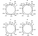
- FIGS. 6A, 6B, 6C, and 6D are plan views showing derivative examples of the frame.
- the frame 23A includes a convex portion 2391A and a convex portion 2394A.
- the protrusion 2391A is the same as the protrusion 239 .
- the convex portion 2394A has a shape that protrudes from the side surface 2344 .
- a plurality of protrusions may be provided.
- the convex portion 2391A corresponds to the "first convex portion" of the present invention
- the convex portion 2394A corresponds to the "second convex portion”.
- the frame 23B includes a convex portion 2391B, a convex portion 2392B, a convex portion 2393B, and a convex portion 2394B.
- the protrusion 2391B is the same as the protrusion 239 .
- the convex portion 2392B has a shape that protrudes from the side surface 2342 .
- the convex portion 2393B has a shape that protrudes from the side surface 2343 .
- the convex portion 2394B has a shape that protrudes from the side surface 2344 .
- the convex portion 2391B corresponds to the "first convex portion" of the invention, and the convex portions 2392B, 2393B, and 2394B correspond to the "second convex portion".
- the convex portion 2392B, the convex portion 2393B, and the convex portion 2394B have the same shape (second shape).
- the protrusion 2391B has a shape (first shape) different from the protrusions 2392B, 2393B, and 2394B.
- the frame 23B has a plurality of protrusions, but only the protrusion 2391B has a different shape. In this way, when a plurality of protrusions are present, by arranging a protrusion having a shape different from other protrusions at a specific position on the side surface of the frame, even if a plurality of protrusions are provided, The orientation of the frame 23B can be easily determined.
- the frame 23C has a convex portion 2391C.
- the protrusion 2391 ⁇ /b>C has a shape protruding from the side surface 2333 .
- the convex portion may have a shape that protrudes from the long side of the octagon of the frame 23C.
- the frame 23D has a projection 2391D.
- Protrusion 2391D is formed at a corner where side 2331 and side 2341 are connected.
- the convex portion may have a shape that protrudes from the corner of the frame 23D.
- the arrangement and shape of the projections of the frames 23A, 23B, 23C, and 23D shown in these derived examples and the arrangement and shape of the projections of the frame 23 can be combined as appropriate, and the effects of each combination can be achieved. can be played.
- the outer shape of the vibrating member 21 and the outer shape of the frame 23 in plan view are octagonal.
- the outer shape of the vibrating member and the outer shape of the frame in plan view may be other polygons.
- the polygon at this time is not limited to a shape having corners where straight lines intersect when viewed from above, and may be a shape composed of curved lines (rounded shape such as R chamfer).
- the outer shape of the vibrating member and the outer shape of the frame may not be completely similar.
Landscapes
- Engineering & Computer Science (AREA)
- Mechanical Engineering (AREA)
- General Engineering & Computer Science (AREA)
- Manufacturing & Machinery (AREA)
- Reciprocating Pumps (AREA)
Priority Applications (3)
| Application Number | Priority Date | Filing Date | Title |
|---|---|---|---|
| JP2023517437A JP7485212B2 (ja) | 2021-04-27 | 2022-04-14 | アクチュエータ、ポンプ、アクチュエータの製造方法 |
| CN202280031127.2A CN117203428A (zh) | 2021-04-27 | 2022-04-14 | 致动器、泵、致动器的制造方法 |
| US18/485,450 US12595788B2 (en) | 2021-04-27 | 2023-10-12 | Actuator, pump, method for manufacturing actuator |
Applications Claiming Priority (2)
| Application Number | Priority Date | Filing Date | Title |
|---|---|---|---|
| JP2021-074741 | 2021-04-27 | ||
| JP2021074741 | 2021-04-27 |
Related Child Applications (1)
| Application Number | Title | Priority Date | Filing Date |
|---|---|---|---|
| US18/485,450 Continuation US12595788B2 (en) | 2021-04-27 | 2023-10-12 | Actuator, pump, method for manufacturing actuator |
Publications (1)
| Publication Number | Publication Date |
|---|---|
| WO2022230677A1 true WO2022230677A1 (ja) | 2022-11-03 |
Family
ID=83847451
Family Applications (1)
| Application Number | Title | Priority Date | Filing Date |
|---|---|---|---|
| PCT/JP2022/017808 Ceased WO2022230677A1 (ja) | 2021-04-27 | 2022-04-14 | アクチュエータ、ポンプ、アクチュエータの製造方法 |
Country Status (4)
| Country | Link |
|---|---|
| US (1) | US12595788B2 (https=) |
| JP (1) | JP7485212B2 (https=) |
| CN (1) | CN117203428A (https=) |
| WO (1) | WO2022230677A1 (https=) |
Cited By (2)
| Publication number | Priority date | Publication date | Assignee | Title |
|---|---|---|---|---|
| WO2025197618A1 (ja) * | 2024-03-19 | 2025-09-25 | 株式会社村田製作所 | アクチュエータおよび流体制御装置 |
| WO2026070336A1 (ja) * | 2024-09-26 | 2026-04-02 | 株式会社村田製作所 | アクチュエータ |
Citations (3)
| Publication number | Priority date | Publication date | Assignee | Title |
|---|---|---|---|---|
| JP2006207436A (ja) * | 2005-01-26 | 2006-08-10 | Matsushita Electric Works Ltd | 圧電ダイヤフラムポンプ |
| JP2008180161A (ja) * | 2007-01-25 | 2008-08-07 | Star Micronics Co Ltd | ダイヤフラムポンプ |
| JP2013100746A (ja) * | 2011-11-08 | 2013-05-23 | Murata Mfg Co Ltd | 流体制御装置 |
Family Cites Families (10)
| Publication number | Priority date | Publication date | Assignee | Title |
|---|---|---|---|---|
| DE10201027C1 (de) * | 2002-01-11 | 2003-08-07 | Eads Deutschland Gmbh | Flüssigkeitspumpe |
| WO2006080566A1 (en) * | 2005-01-26 | 2006-08-03 | Matsushita Electric Works, Ltd. | Piezoelectric-driven diaphragm pump |
| EP2557312B1 (en) | 2010-05-21 | 2019-11-13 | Murata Manufacturing Co., Ltd. | Fluid pump |
| EP2698537B1 (en) * | 2011-04-11 | 2018-10-17 | Murata Manufacturing Co., Ltd. | Actuator-support structure and pump device |
| JP5682513B2 (ja) * | 2011-09-06 | 2015-03-11 | 株式会社村田製作所 | 流体制御装置 |
| JP6001482B2 (ja) * | 2013-03-25 | 2016-10-05 | 京セラ株式会社 | 入力装置および電子機器 |
| EP3604810B1 (en) * | 2014-02-21 | 2023-06-28 | Murata Manufacturing Co., Ltd. | Fluid control device and pump |
| WO2016172866A1 (en) * | 2015-04-29 | 2016-11-03 | Tgoertek Inc. | Piezoelectric speaker and method for forming the same |
| JP2017052135A (ja) * | 2015-09-08 | 2017-03-16 | セイコーエプソン株式会社 | Memsデバイス、液体噴射ヘッド、液体噴射装置、memsデバイスの製造方法、及び液体噴射ヘッドの製造方法 |
| TWI683959B (zh) * | 2016-09-05 | 2020-02-01 | 研能科技股份有限公司 | 壓電致動器及其所適用之微型流體控制裝置 |
-
2022
- 2022-04-14 WO PCT/JP2022/017808 patent/WO2022230677A1/ja not_active Ceased
- 2022-04-14 JP JP2023517437A patent/JP7485212B2/ja active Active
- 2022-04-14 CN CN202280031127.2A patent/CN117203428A/zh active Pending
-
2023
- 2023-10-12 US US18/485,450 patent/US12595788B2/en active Active
Patent Citations (3)
| Publication number | Priority date | Publication date | Assignee | Title |
|---|---|---|---|---|
| JP2006207436A (ja) * | 2005-01-26 | 2006-08-10 | Matsushita Electric Works Ltd | 圧電ダイヤフラムポンプ |
| JP2008180161A (ja) * | 2007-01-25 | 2008-08-07 | Star Micronics Co Ltd | ダイヤフラムポンプ |
| JP2013100746A (ja) * | 2011-11-08 | 2013-05-23 | Murata Mfg Co Ltd | 流体制御装置 |
Cited By (2)
| Publication number | Priority date | Publication date | Assignee | Title |
|---|---|---|---|---|
| WO2025197618A1 (ja) * | 2024-03-19 | 2025-09-25 | 株式会社村田製作所 | アクチュエータおよび流体制御装置 |
| WO2026070336A1 (ja) * | 2024-09-26 | 2026-04-02 | 株式会社村田製作所 | アクチュエータ |
Also Published As
| Publication number | Publication date |
|---|---|
| CN117203428A (zh) | 2023-12-08 |
| US20240044323A1 (en) | 2024-02-08 |
| JP7485212B2 (ja) | 2024-05-16 |
| JPWO2022230677A1 (https=) | 2022-11-03 |
| US12595788B2 (en) | 2026-04-07 |
Similar Documents
| Publication | Publication Date | Title |
|---|---|---|
| US9482217B2 (en) | Fluid control device | |
| US9028226B2 (en) | Fluid control device | |
| WO2022230677A1 (ja) | アクチュエータ、ポンプ、アクチュエータの製造方法 | |
| US12313054B2 (en) | Fluid control device | |
| CN115210469B (zh) | 流体控制装置 | |
| CN112752906A (zh) | 泵 | |
| CN108696808B (zh) | 扬声器及扬声器装配方法 | |
| JP6127361B2 (ja) | 流体制御装置 | |
| JP2002010393A (ja) | 圧電型電気音響変換器 | |
| US12276274B2 (en) | Fluid control device | |
| CN114041013B (zh) | 流体控制装置 | |
| CN114746650B (zh) | 致动器以及流体控制装置 | |
| CN115315320A (zh) | 致动器、流体控制装置和致动器的制造方法 | |
| JP7550066B2 (ja) | 振動デバイス | |
| CN114127421B (zh) | 流体控制装置 | |
| WO2024135219A1 (ja) | 流体制御装置 | |
| CN117156327A (zh) | 音响器件 | |
| JP2026059541A (ja) | アクチュエータ | |
| WO2025197618A1 (ja) | アクチュエータおよび流体制御装置 | |
| WO2025134808A1 (ja) | アクチュエータ | |
| WO2025197617A1 (ja) | アクチュエータおよび流体制御装置 | |
| WO2022259941A1 (ja) | 超音波トランスデューサ及び非接触触覚提示デバイス | |
| JPH0269100A (ja) | 圧電発音体および圧電スピーカ |
Legal Events
| Date | Code | Title | Description |
|---|---|---|---|
| 121 | Ep: the epo has been informed by wipo that ep was designated in this application |
Ref document number: 22795591 Country of ref document: EP Kind code of ref document: A1 |
|
| ENP | Entry into the national phase |
Ref document number: 2023517437 Country of ref document: JP Kind code of ref document: A |
|
| WWE | Wipo information: entry into national phase |
Ref document number: 202280031127.2 Country of ref document: CN |
|
| NENP | Non-entry into the national phase |
Ref country code: DE |
|
| 122 | Ep: pct application non-entry in european phase |
Ref document number: 22795591 Country of ref document: EP Kind code of ref document: A1 |