WO2022230610A1 - Moyeu et véhicule électrique - Google Patents
Moyeu et véhicule électrique Download PDFInfo
- Publication number
- WO2022230610A1 WO2022230610A1 PCT/JP2022/016729 JP2022016729W WO2022230610A1 WO 2022230610 A1 WO2022230610 A1 WO 2022230610A1 JP 2022016729 W JP2022016729 W JP 2022016729W WO 2022230610 A1 WO2022230610 A1 WO 2022230610A1
- Authority
- WO
- WIPO (PCT)
- Prior art keywords
- hub
- shaft
- opening
- central axis
- axial direction
- Prior art date
Links
- WABPQHHGFIMREM-UHFFFAOYSA-N lead(0) Chemical compound [Pb] WABPQHHGFIMREM-UHFFFAOYSA-N 0.000 claims abstract description 33
- 230000002093 peripheral effect Effects 0.000 claims description 29
- 239000004020 conductor Substances 0.000 claims description 4
- 238000004804 winding Methods 0.000 claims description 4
- 230000004323 axial length Effects 0.000 claims description 3
- 230000000149 penetrating effect Effects 0.000 claims description 3
- 230000005540 biological transmission Effects 0.000 description 9
- 238000000034 method Methods 0.000 description 9
- 239000012212 insulator Substances 0.000 description 5
- 238000003466 welding Methods 0.000 description 4
- 238000010586 diagram Methods 0.000 description 2
- 238000012986 modification Methods 0.000 description 2
- 230000004048 modification Effects 0.000 description 2
- 229910000831 Steel Inorganic materials 0.000 description 1
- 238000010276 construction Methods 0.000 description 1
- 238000002788 crimping Methods 0.000 description 1
- 238000010030 laminating Methods 0.000 description 1
- 239000006247 magnetic powder Substances 0.000 description 1
- 238000004519 manufacturing process Methods 0.000 description 1
- 238000010248 power generation Methods 0.000 description 1
- 238000005245 sintering Methods 0.000 description 1
- 239000010959 steel Substances 0.000 description 1
Images


Classifications
-
- H—ELECTRICITY
- H02—GENERATION; CONVERSION OR DISTRIBUTION OF ELECTRIC POWER
- H02K—DYNAMO-ELECTRIC MACHINES
- H02K7/00—Arrangements for handling mechanical energy structurally associated with dynamo-electric machines, e.g. structural association with mechanical driving motors or auxiliary dynamo-electric machines
- H02K7/14—Structural association with mechanical loads, e.g. with hand-held machine tools or fans
-
- B—PERFORMING OPERATIONS; TRANSPORTING
- B60—VEHICLES IN GENERAL
- B60B—VEHICLE WHEELS; CASTORS; AXLES FOR WHEELS OR CASTORS; INCREASING WHEEL ADHESION
- B60B27/00—Hubs
- B60B27/0047—Hubs characterised by functional integration of other elements
-
- B—PERFORMING OPERATIONS; TRANSPORTING
- B60—VEHICLES IN GENERAL
- B60B—VEHICLE WHEELS; CASTORS; AXLES FOR WHEELS OR CASTORS; INCREASING WHEEL ADHESION
- B60B27/00—Hubs
- B60B27/02—Hubs adapted to be rotatably arranged on axle
- B60B27/023—Hubs adapted to be rotatably arranged on axle specially adapted for bicycles
-
- B—PERFORMING OPERATIONS; TRANSPORTING
- B62—LAND VEHICLES FOR TRAVELLING OTHERWISE THAN ON RAILS
- B62J—CYCLE SADDLES OR SEATS; AUXILIARY DEVICES OR ACCESSORIES SPECIALLY ADAPTED TO CYCLES AND NOT OTHERWISE PROVIDED FOR, e.g. ARTICLE CARRIERS OR CYCLE PROTECTORS
- B62J11/00—Supporting arrangements specially adapted for fastening specific devices to cycles, e.g. supports for attaching maps
- B62J11/10—Supporting arrangements specially adapted for fastening specific devices to cycles, e.g. supports for attaching maps for mechanical cables, hoses, pipes or electric wires, e.g. cable guides
- B62J11/19—Supporting arrangements specially adapted for fastening specific devices to cycles, e.g. supports for attaching maps for mechanical cables, hoses, pipes or electric wires, e.g. cable guides specially adapted for electric wires
-
- B—PERFORMING OPERATIONS; TRANSPORTING
- B62—LAND VEHICLES FOR TRAVELLING OTHERWISE THAN ON RAILS
- B62M—RIDER PROPULSION OF WHEELED VEHICLES OR SLEDGES; POWERED PROPULSION OF SLEDGES OR SINGLE-TRACK CYCLES; TRANSMISSIONS SPECIALLY ADAPTED FOR SUCH VEHICLES
- B62M6/00—Rider propulsion of wheeled vehicles with additional source of power, e.g. combustion engine or electric motor
- B62M6/40—Rider propelled cycles with auxiliary electric motor
- B62M6/60—Rider propelled cycles with auxiliary electric motor power-driven at axle parts
- B62M6/65—Rider propelled cycles with auxiliary electric motor power-driven at axle parts with axle and driving shaft arranged coaxially
-
- H—ELECTRICITY
- H02—GENERATION; CONVERSION OR DISTRIBUTION OF ELECTRIC POWER
- H02K—DYNAMO-ELECTRIC MACHINES
- H02K5/00—Casings; Enclosures; Supports
- H02K5/04—Casings or enclosures characterised by the shape, form or construction thereof
- H02K5/22—Auxiliary parts of casings not covered by groups H02K5/06-H02K5/20, e.g. shaped to form connection boxes or terminal boxes
- H02K5/225—Terminal boxes or connection arrangements
-
- H—ELECTRICITY
- H02—GENERATION; CONVERSION OR DISTRIBUTION OF ELECTRIC POWER
- H02K—DYNAMO-ELECTRIC MACHINES
- H02K7/00—Arrangements for handling mechanical energy structurally associated with dynamo-electric machines, e.g. structural association with mechanical driving motors or auxiliary dynamo-electric machines
- H02K7/10—Structural association with clutches, brakes, gears, pulleys or mechanical starters
- H02K7/116—Structural association with clutches, brakes, gears, pulleys or mechanical starters with gears
-
- B—PERFORMING OPERATIONS; TRANSPORTING
- B62—LAND VEHICLES FOR TRAVELLING OTHERWISE THAN ON RAILS
- B62M—RIDER PROPULSION OF WHEELED VEHICLES OR SLEDGES; POWERED PROPULSION OF SLEDGES OR SINGLE-TRACK CYCLES; TRANSMISSIONS SPECIALLY ADAPTED FOR SUCH VEHICLES
- B62M11/00—Transmissions characterised by the use of interengaging toothed wheels or frictionally-engaging wheels
- B62M11/04—Transmissions characterised by the use of interengaging toothed wheels or frictionally-engaging wheels of changeable ratio
- B62M11/14—Transmissions characterised by the use of interengaging toothed wheels or frictionally-engaging wheels of changeable ratio with planetary gears
- B62M11/16—Transmissions characterised by the use of interengaging toothed wheels or frictionally-engaging wheels of changeable ratio with planetary gears built in, or adjacent to, the ground-wheel hub
-
- H—ELECTRICITY
- H02—GENERATION; CONVERSION OR DISTRIBUTION OF ELECTRIC POWER
- H02K—DYNAMO-ELECTRIC MACHINES
- H02K2213/00—Specific aspects, not otherwise provided for and not covered by codes H02K2201/00 - H02K2211/00
- H02K2213/03—Machines characterised by numerical values, ranges, mathematical expressions or similar information
-
- Y—GENERAL TAGGING OF NEW TECHNOLOGICAL DEVELOPMENTS; GENERAL TAGGING OF CROSS-SECTIONAL TECHNOLOGIES SPANNING OVER SEVERAL SECTIONS OF THE IPC; TECHNICAL SUBJECTS COVERED BY FORMER USPC CROSS-REFERENCE ART COLLECTIONS [XRACs] AND DIGESTS
- Y02—TECHNOLOGIES OR APPLICATIONS FOR MITIGATION OR ADAPTATION AGAINST CLIMATE CHANGE
- Y02T—CLIMATE CHANGE MITIGATION TECHNOLOGIES RELATED TO TRANSPORTATION
- Y02T10/00—Road transport of goods or passengers
- Y02T10/60—Other road transportation technologies with climate change mitigation effect
- Y02T10/64—Electric machine technologies in electromobility
Definitions
- the present invention relates to a hub arranged at the center of a wheel of an electric vehicle and an electric vehicle having the same.
- a hub having a rotor and a stator having coils is conventionally known.
- This kind of hub has wires that are connected to the coils.
- the hub has a hub axle, and the hub axle is formed with a wiring passage opening at the tip. The wiring passes through the wiring passage and is pulled out from the end of the hub axle.
- An object of the present invention is to provide a hub to which lead wires can be easily attached.
- the exemplary hub of the present invention is placed in the center of the wheel.
- the hub is formed by winding a hub shaft extending along the central axis and protruding on one side in the axial direction to the outside, a tubular hub body rotatably disposed on the hub shaft and extending in the axial direction, and a conductive wire. and a rotor shaft extending along the central axis, facing radially or axially to the stator and rotating with respect to the stator. A reversibly arranged rotor and leads electrically connected to the conductors.
- the rotor shaft is connected to the hub body.
- the hub shaft has a through hole penetrating from the other end in the axial direction to the outer peripheral surface.
- the through hole has a first opening formed in the outer peripheral surface of the hub shaft, and the lead wire is arranged in the through hole.
- the end portion on one side in the axial direction and the end portion on the other side in the axial direction of the first opening differ in position in the circumferential direction with respect to the central axis.
- the exemplary hub of the present invention allows easy attachment of leads.
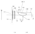
- FIG. 1 is a schematic diagram of an electric vehicle according to an embodiment of the invention.
- FIG. 2 is a perspective view of the hub attached to the front fork.
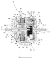
- FIG. 3 is a cross-sectional view of the hub taken along a vertical plane and viewed from the front.
- FIG. 4 is a perspective view of the right hub shaft as viewed from below the front.
- FIG. 5 is a perspective view of the right hub shaft with lead wires removed, as viewed from below.
- FIG. 6 is a bottom view of the right hub shaft.
- FIG. 7 is a rear view of the right hub shaft.
- FIG. 8 is a view of the right hub shaft viewed from the right along the center axis.
- FIG. 9 is a view of the right hub shaft viewed from the left along the central axis.
- FIG. 10 is a perspective view of the right hub shaft of the first modified example as seen from the front lower side.
- FIG. 11 is a view of the right hub shaft viewed from the right along the central
- FIG. 1 is a schematic diagram of an electric vehicle according to an embodiment of the present invention.
- the electric vehicle 100 is an electrically assisted bicycle that assists the user's stepping force on the pedals 106 .
- an electric vehicle 100 has a vehicle body 101 , two wheels 102 , a power transmission mechanism 103 and a power supply section 104 .
- the vehicle body 101 includes a handle 107 and a saddle 108.
- Two wheels 102 , a power transmission mechanism 103 and a power supply section 104 are attached to the vehicle body 101 .
- the two wheels 102 are attached to the front portion of the vehicle body 101 as a front wheel 102f and to the rear portion as a rear wheel 102r.
- a power transmission mechanism 103 is connected to the rear wheel 102r.
- a hub 10 is arranged in the center of the front wheel 102f.
- the power transmission mechanism 103 includes a crank 105 attached to a crankshaft 105a and a pedal 106.
- the power transmission mechanism 103 further includes a drive gear, a driven gear attached to the rear wheel 102r, and a chain (not shown) connecting the drive gear and the driven gear.
- the crank 105 is fixed to a crankshaft 105a rotatably attached to the vehicle body 101.
- a pedal 106 is rotatably attached to the tip of the crank 105 .
- the power supply unit 104 is attached to the vehicle body 101 .
- the power supply unit 104 is, for example, a battery, and is built in the vehicle body 101 as shown in FIG.
- the configuration is not limited to this, and a configuration that is attached to the vehicle body 101 and can supply power to the hub 10 can be widely adopted.
- the hub 10 is attached to the lower end of the front fork Fk that is part of the vehicle body 101 (see FIG. 2 described later).
- the front fork Fk has a concave hub mounting portion Fk1 that opens downward at its lower end.
- the hub 10 has a second shaft portion 112 of a hub shaft 11, which will be described later, which protrudes to both the left and right ends, and is arranged in the hub mounting portion Fk1.
- a nut Nt is attached to a male thread (not shown) formed on the outer peripheral surface of the second shaft portion 112 and tightened. Thereby, the hub 10 is attached to the front fork Fk (see FIG. 2, which will be described later).
- FIG. 2 is a perspective view of the hub 10 attached to the front fork Fk.
- 3 is a cross-sectional view of the hub 10 taken along a vertical plane and viewed from the front F.
- the hub 10 is arranged in the center of the front wheel 102f and connected to an annular rim Rm (see FIG. 1) included in the front wheel 102f via spokes Sp (see FIG. 1).
- the electric power is supplied to drive the motor unit 20 housed therein.
- the torque of the motor section 20 drives the front wheels 102f. That is, in the present embodiment, hub 10 is a driving device for electric vehicle 100 .
- the hub 10 is not limited to the front wheel 102f, and may be arranged on the rear wheel 102r, or may be arranged on both the front wheel 102f and the rear wheel 102r. That is, hub 10 is arranged in the center of wheel 102 .
- the hub 10 has a hub shaft 11 , a hub body 12 , a motor section 20 and a speed reduction mechanism 30 .
- a hub shaft 11 protrudes axially rightward R and leftward L. As shown in FIG.
- the motor unit 20 is a DC brushless motor.
- the motor section 20 is driven by power from the power supply section 104 .
- the motor section 20 has a stator 21 and a rotor 25 . A portion of the stator 21 and the rotor 25 are arranged inside the housing 50 .
- the motor section 20 is an inner rotor type motor in which a rotor 25 is arranged radially inward of a stator 21 .
- the motor unit 20 is not limited to an inner rotor type motor, and may be an outer rotor type motor. Also, it may be a so-called axial gap motor in which a stator and a rotor are arranged facing each other in the axial direction.
- the stator 21 has a stator core 22 , coils 23 and insulators 24 .
- Stator 21 is held in housing 50 .
- Stator core 22 has a core back 221 and a plurality of teeth 222 .
- the core back 221 has an annular shape.
- a radial outer surface of the core back 221 is fixed to the housing 50 .
- the teeth 222 protrude from the radial inner surface of the core back 221 in a direction toward the central axis J1.
- the multiple teeth 222 are arranged at regular intervals in the circumferential direction.
- the insulator 24 covers at least the teeth 222 .
- the insulator 24 has insulating properties.
- Coil 23 is formed by winding a conductive wire around teeth 222 covered with insulator 24 . That is, the stator 21 has a coil 23 formed by winding a conducting wire.
- the rotor 25 has a rotor shaft 26 , a rotor core 27 and rotor magnets 28 .
- the rotor shaft 26 has a substantially cylindrical shape. As shown in FIG. 3, the rotor shaft 26 extends along the central axis J1.
- the motor section 20 has a rotor shaft 26 extending along the central axis J ⁇ b>1 , and a rotor 25 that radially faces the stator 21 and is rotatably arranged with respect to the stator 21 .
- the rotor shaft 26 is rotatable around the central axis J1.
- the rotor shaft 26 is rotatably supported by the housing 50 via shaft bearings 261 .
- the shaft bearings 261 are arranged at two axially spaced locations, and rotatably support the rotor shaft 26 at two axially spaced locations.
- the shaft bearing 261 is here a ball bearing, but is not so limited. A bearing structure that can support the rotor shaft 26 smoothly and accurately can be widely adopted.
- the rotor 25 is fixed to the outer circumference of the rotor shaft 26 .
- the rotor 25 has a rotor core 27 and rotor magnets 28 .
- the rotor 25 rotates around a horizontally extending central axis J1.
- the rotor core 27 is formed by laminating thin electromagnetic steel sheets.
- the rotor core 27 is a cylindrical body extending along the axial direction.
- the rotor core 27 may be formed by sintering magnetic powder.
- a plurality of rotor magnets 28 are fixed to the rotor core 27 .
- a plurality of rotor magnets 28 are arranged along the circumferential direction with magnetic poles alternated.
- the housing 50 is cylindrical.
- the housing 50 has a first housing portion 51 and a second housing portion 52 .
- the first housing portion 51 has a bottomed cylindrical shape having a bottom portion 511 on the right side R in the axial direction, and has an opening on the left side L. As shown in FIG. In other words, it has an opening toward the left L.
- the second housing part 52 has a bottomed cylindrical shape having a bottom portion 521 on the left side L in the axial direction, and has an opening on the right side R. As shown in FIG. In other words, it has an opening toward the right R.
- the opening of the first housing part 51 holds the axial right end of the stator 21 . Also, the opening of the second housing portion 52 holds the axial left end portion of the stator 21 .
- the first housing part 51 and the second housing part 52 are arranged apart in the axial direction. More specifically, the first housing portion 51 and the second housing portion 52 are attached to the stator 21 axially spaced apart.
- the rotor shaft 26 is rotatably supported by the bottom portion 511 of the first housing portion 51 and the bottom portion 521 of the second housing portion 52 via shaft bearings 261 .
- the axial left end L of the rotor shaft 26 passes through a through hole 522 formed in the bottom portion 521 of the second housing portion 52 .
- a later-described sun gear portion 31 of the speed reduction mechanism 30 is arranged in a portion of the rotor shaft 26 that protrudes leftward from the bottom portion 521 of the second housing portion 52 .
- Auxiliaries such as a bus bar 29 are attached to the right R end of the motor section 20 .
- the busbar 29 is a conductive member to which the conductor wire of the coil 23 is connected.
- a lead wire 40 is connected to the bus bar 29 .
- a current is supplied from the power supply unit 104 to the coil 23 via the lead wire 40 and the bus bar 29 . That is, the lead wire 40 is electrically connected to the conductor wire of the coil 23 .
- the motor section 20 is driven by power supplied from the power supply section 104 . That is, the coil 23 is excited by the current supplied from the power supply unit 104 being supplied to the coil 23 . Magnetic force is generated between the rotor magnet 28 of the rotor 25 and the coil 23 being magnetized. By exciting the plurality of coils 23 at appropriate timing, torque is generated in the rotor 25 in the circumferential direction around the central axis J1. This torque causes the rotor shaft 26 to rotate around the central axis J1.
- the speed reduction mechanism 30 has a sun gear portion 31, a planetary gear portion 32, an internal gear portion 33, and a torque limiter .
- the deceleration mechanism 30 uses a so-called planetary gear mechanism to decelerate the rotation of the rotor shaft 26 and transmit it to the hub body 12 .
- the sun gear portion 31 is arranged at the left end L of the rotor shaft 26 in the axial direction.
- the sun gear portion 31 rotates integrally with the rotor shaft 26 . Therefore, the sun gear portion 31 may be formed as a single member with the rotor shaft 26, or may be mounted on the rotor shaft 26 and fixed by a fixing method such as adhesion, welding, screwing, crimping, or press-fitting. may Moreover, you may employ
- the speed reduction mechanism 30 has a plurality of planetary gear portions 32.
- the number of planetary gear portions 32 may be three or four, but is not limited to this.
- the plurality of planetary gear portions 32 are arranged in the circumferential direction.
- the plurality of planetary gear portions 32 are arranged side by side at equal intervals in the circumferential direction.
- the planetary gear portion 32 meshes with the sun gear portion 31 .
- the speed reduction mechanism 30 of the present embodiment has three planetary gear units 32, but the number is not limited to three. It is sufficient if two or more planetary gear portions 32 are provided.
- the arrangement of the planetary gear portions 32 in the circumferential direction is not limited to equal intervals. That is, the plurality of planetary gear portions 32 mesh with the sun gear portion 31 and are arranged in the circumferential direction.
- the planetary gear portion 32 will be further explained.
- the planetary gear portion 32 has a first planetary gear 321 and a second planetary gear 322 . More specifically, the planetary gear section 32 has a planetary shaft 320 , a first planetary gear 321 and a second planetary gear 322 .
- the planetary shaft 320 extends along a planetary axis J2 parallel to the central axis J1. As shown in FIG. 3 , the axial right end of the planetary shaft 320 is fixed to the bottom portion 521 of the second housing portion 52 . Also, the upper end of the planetary shaft 320 is fixed to the left hub shaft 11L. That is, the position of the planetary gear portion 32 relative to the central axis J1 of the planetary shaft J2 is fixed.
- the first planetary gear 321 and the second planetary gear 322 are rotatably supported by the planetary shaft 320 .
- the first planetary gear 321 and the second planetary gear 322 are axially connected.
- the second planetary gear 322 rotates together with the first planetary gear 321 .
- the planetary gear portion 32 is a two-stage gear.
- the planetary gear portion 32 is not limited to a two-stage gear.
- the planetary gear portion 32 may be a multi-stage gear having three or more stages, or may have a single diameter, that is, a configuration having only a gear with a predetermined number of teeth.
- the first planetary gear 321 and the second planetary gear 322 may be formed of a single member, or may be combined in the axial direction and fixed using a fixing method such as adhesion, welding, or screwing. good too.
- the internal gear portion 33 is an annular gear. Internal teeth are formed on the radially inner surface.
- the internal gear portion 33 meshes with the second planetary gear 322 of the planetary gear portion 32 .
- the internal gear portion 33 has a cylindrical shape, and a torque limiter 34 is arranged at the left end L in the axial direction. The torque limiter 34 contacts the inner peripheral surface of the internal gear portion 33 .
- the torque limiter 34 has a torque limiter outer ring 341 and a torque limiter inner ring 342 .
- the torque limiter outer ring 341 rotates together with the internal gear portion 33 around the central axis J1.
- Torque limiter inner ring 342 rotates integrally with hub body lid portion 122 of hub body 12 .
- the rotation of the torque limiter outer ring 341 is transmitted to the torque limiter inner ring 342 when the torque limiter inner ring 342 is rotated in the rotational direction Rt of the front wheel 102f.
- a planetary gear mechanism is adopted as the speed reduction mechanism 30, but it is not limited to this. It is possible to widely adopt a configuration capable of decelerating the rotation of the motor section 20 .
- the rotor shaft 26 of the motor section 20 may be connected to the hub body 12 directly or via a torque limiter.
- the rotor shaft 26 is directly or indirectly connected to the hub body 12 . That is, rotor shaft 26 is connected to hub body 12 .
- the hub 10 has two hub shafts 11.
- the right R hub shaft 11 is divided into the right hub shaft 11R
- the left hub shaft 11 is divided into the left hub shaft 11L.
- the center of each hub shaft 11 overlaps with the central axis J1. That is, the hub shaft 11R extends along the central axis J1 and protrudes outward on one axial side.
- the hub shaft 11 has a first shaft portion 111 , a second shaft portion 112 and a flange portion 113 .
- the first shaft portion 111 has a cylindrical shape centered on the central axis J1 and extends along the central axis J1. That is, the hub shaft 11R has a columnar first shaft portion 111 extending along the central axis J1.
- the second shaft portion 112 has a cylindrical shape centered on the central axis J1.
- the outer diameter of the second shaft portion 112 is smaller than the outer diameter of the first shaft portion 111 .
- the second shaft portion 112 extends along the central axis J1 from one side of the first shaft portion 111 in the direction along the central axis J1, which is the outer end face along the central axis J1 in FIG. That is, the hub shaft 11R has a columnar second shaft portion 112 that protrudes in the direction along the central axis J1 from one axial end of the first shaft portion 111 and has a diameter smaller than that of the first shaft portion 111 .
- a male thread (not shown) is formed on the outer peripheral surface of the second shaft portion 112 .
- the flange portion 113 extends radially outward from the other side of the first shaft portion 111 in the direction along the central axis J1, which is the outer peripheral surface along the central axis J1 in FIG.
- the flange portion 113 is annular.
- the motor portion 20 is fixed to the flange portion 113 .
- both the right hub shaft 11R and the left hub shaft 11L have the above construction.
- the right hub shaft 11R and the left hub shaft 11L are integrally molded bodies, they are not limited to this and may be partly formed separately.
- the second shaft portion 112 may be formed in a cylindrical shape, and the first shaft portion 111 may be fixed by a fixing method such as press fitting.
- other configurations may be used.
- the respective centers of the right hub shaft 11R and the left hub shaft 11L coincide with the central axis J1.
- the right hub shaft 11R and the left hub shaft 11L have the same central axis J1 and are arranged apart in the direction of the central axis J1.
- the flange portion 13 of the right hub shaft 11R is fixed to the bottom portion 511 of the first housing portion 51. Also, the flange portion 13 of the left hub shaft 11L is fixed to the bottom portion 521 of the second housing portion 52 via the planetary shaft 320 . Thereby, the stator 21 of the motor portion 20 is fixed to the hub shaft 11 .
- the hub 10 has lead wires 40 that connect the motor section 20 housed inside and a control section (not shown) arranged outside. As shown in FIG. 3, in the hub 10, the lead wire 40 is drawn out from the right side of the hub 10, that is, from the right hub shaft 11R. In addition, in the hub 10 of the present embodiment, the lead wire 40 is drawn out from the right side, but it is not limited to this, and may be drawn out from the left side. In this case, the right hub shaft 11R and the left hub shaft 11L are interchanged.
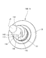
- FIG. 4 is a perspective view of the right hub shaft 11R viewed from the front and lower side.
- FIG. 5 is a perspective view of the right hub shaft 11R with lead wires removed, as viewed from below.
- FIG. 6 is a bottom view of the right hub shaft 11R.
- FIG. 7 is a rear view of the right hub shaft 11R.
- FIG. 8 is a view of the right hub shaft 11R viewed from the right side along the central axis J1.
- FIG. 9 is a view of the right hub shaft 11R viewed from the left along the central axis J1. Note that in FIG. 8, a part of the front fork Fk is indicated by a dashed line.
- the right hub shaft 11R has a through hole 114 and a first projecting portion 115.
- the first protrusion 115 protrudes rightward from the right end of the first shaft portion 111 .
- the first projecting portion 115 is connected to the outer peripheral surface of the second shaft portion 112 . That is, the first projecting portion 115 axially projects from one end of the first shaft portion 111 in the axial direction and is arranged on the radially outer peripheral side of the second shaft portion 112 .
- the first projecting portion 115 according to this embodiment is formed of a single member together with both the first shaft portion 111 and the second shaft portion 112 .
- the first projecting portion 115 may be formed separately from the first shaft portion 111 or the second shaft portion 112 and fixed by a fixing method such as welding or screwing.
- the through hole 114 penetrates from the left end of the right hub shaft 11R in the direction along the central axis J1 toward the outer peripheral surface. That is, the hub shaft 11R has a through hole 114 penetrating from the other end in the axial direction to the outer peripheral surface.
- lead wire 40 is placed in through hole 114 .
- Both ends of the through-hole 114 have a first opening 116 and a second opening 117 at both ends in the axial direction. That is, the through hole 114 has a first opening 116 formed on the outer peripheral surface of the hub shaft 11R.
- the first opening 116 is formed on the outer peripheral surface of the first shaft portion 111, the right end surface along the central axis J1, and the outer peripheral surface of the second shaft portion 112. That is, a portion of the first opening 116 is formed on the outer peripheral surface of the first shaft portion 111 , the outer peripheral surface of the second shaft portion 112 , and the outer surface of the first protruding portion 115 .
- the rigidity of the right hub shaft 11R can be increased.
- the first projecting portion 115 is attached in contact with the front fork Fk, positional deviation of the hub 10 with respect to the front fork Fk can be suppressed.
- the first opening 116 is formed in the first projecting portion 115, the through hole 114 can be made longer, and the lead wire 40 can be stably held.
- the right R end 1162 and the left L end 1163 of the first opening 116 along the central axis J1 are located at different positions in the circumferential direction. That is, the end portion 1162 on one side in the axial direction of the first opening 116 and the end portion 1163 on the other side in the axial direction are different in position in the circumferential direction with respect to the central axis J1.
- the first opening 116 can be made larger than when the opening for drawing out the lead wire 40 is formed along the axial direction. This facilitates drawing out the lead wire 40 .
- the movable range of the lead wire 40 is increased by increasing the size of the first opening 116, handling of the drawn lead wire 40 is facilitated. From the above, it is possible to attach the hub 10 to front forks Fk having different shapes.
- the first protrusion 115 is arranged behind the first opening 116 in the rotation direction Rt of the wheel 102f.
- the hub body 12 rotates in the rotation direction Rt by the torque output from the motor portion 20 .
- a reaction force opposite to the rotational direction Rt acts on the right hub shaft 11R.
- the first projecting portion 115 of the right hub shaft 11R is pressed against the hub mounting portion Fk1 of the front fork Fk. Since the right hub shaft 11R has the first projecting portion 115, the rigidity of the portion of the right hub shaft 11R that contacts the hub mounting portion Fk1 can be increased. As a result, it is possible to receive reaction force when the wheel 102f rotates, and to firmly fix the right hub shaft 11R to the front fork Fk.
- a portion of the first opening 116 is formed at one end of the first shaft portion 111 in the axial direction.
- the portion formed at 111 has a curved portion 1161 that curves outwardly around the periphery.
- the through hole 114 has a first opening 116 and a second opening 117 at both ends.
- the second opening 117 is formed at the left end L in the axial direction of the flange portion 113 . That is, the through hole 114 has a second opening 117 that opens on the other side in the axial direction of the hub shaft 11R.
- the first opening 116 has a portion that overlaps the second opening 117 in the axial direction when viewed from the direction along the central axis J1.
- the second opening 117 is radially deviated from the central axis J1.
- the center of the second opening 11 and the position of the central axis J1 are different when viewed from the direction of the central axis J1.
- part of the first opening 116 is formed on the outer peripheral surface of the first shaft portion 111 .
- the length L1 from the end on one side in the axial direction of the first opening 116 formed in the outer peripheral surface of the first shaft portion 111 to the end on the other side in the axial direction is It may be shorter than the axial length L2.
- the guide for the lead wire 40 can be lengthened. As a result, the lead wire 40 can be stably routed along the right hub shaft 11R.
- the hub body 12 is rotatably supported by the hub shaft 11 via the hub bearing Br.
- the hub body 12 is rotatably arranged on the hub shaft 11 and has a tubular shape extending in the axial direction.
- the hub body 12 has a case portion 121 and a hub body lid portion 122 .
- the case portion 121 has a bottomed tubular shape extending along the central axis J1.
- the case portion 121 has a hub body tubular portion 123 and a hub body bottom portion 124 .
- the hub body tubular portion 123 has a cylindrical shape centered on the central axis J1.
- the hub body bottom portion 124 extends radially inward from the right end of the hub body cylindrical portion 123 in the direction along the central axis J1.
- a bottom through-hole 125 is formed in the radially central portion of the hub body bottom 124 so as to extend therethrough in the axial direction.
- the right hub shaft 11R passes through the bottom through hole 125.
- the hub body bottom portion 124 is rotatably supported by the right hub shaft 11R via a hub bearing Br.
- case portion 121 has two hub flange portions 126 extending radially outward from the outer peripheral surface.
- the two hub flange portions 126 are axially spaced apart.
- the hub flange portion 126 has spoke holes 127 into which the spokes Sp are inserted.
- the hub body lid portion 122 is fixed to the axial left end L of the hub body cylindrical portion 123 of the case portion 121 .
- Hub body lid portion 122 is arranged to axially face hub body bottom portion 124 of case portion 121 .
- the internal space 120 of the hub body 12 is formed by fixing the hub body lid portion 122 to the hub body cylindrical portion 123 .
- the motor section 20 and the speed reduction mechanism 30 are accommodated in the internal space 120 . That is, the stator 21 is arranged inside the hub body 12 .
- the hub body lid portion 122 is fixed to the hub body cylindrical portion 123 by screwing, for example.
- a fixing method such as press fitting, adhesion, or welding.
- a wide variety of methods can be employed to firmly fix the hub body lid portion 122 to the hub body tubular portion 123 .
- the hub body lid portion 122 is rotatably supported by the left hub shaft 11L via the hub bearing Br.
- the coil 23 of the motor section 20 arranged inside the hub body 12 is connected to the lead wire 40 via the bus bar 29 .
- a current is supplied to the coil 23 via a lead wire 40 .
- the coil 23 is excited.
- a magnetic force is generated between the excited coil 23 and the rotor magnet 28 .
- the rotor 25 rotates.
- the rotation of the rotor 25 causes the rotor shaft 26 to rotate.
- the rotation of the rotor shaft 26 causes the sun gear portion 31 to rotate.
- Rotation of the sun gear portion 31 is transmitted to the planetary gear portion 32 and transmitted from the planetary gear portion 32 to the internal gear portion 33 .
- the internal gear portion 33 rotates.
- the internal gear portion 33 is connected to the hub body lid portion 122 of the hub body 12 via the torque limiter 34 .
- the internal gear portion 33 rotates in the rotational direction Rt (see FIG. 8)
- the rotation of the internal gear portion 33 is transmitted to the hub body lid portion 122 .
- the hub body 12 rotates with respect to the hub shaft 11 .
- the rim Rm is rotated via the spokes Sp attached to the hub flange portion 126 of the hub body 12, and the tire Ty attached to the rim Rm rolls on the ground, whereby the electric vehicle 100 is driven.
- the structure is simplified compared to a configuration including an electric drive unit that drives or assists the power transmission mechanism 103. be able to. Further, a motor section 20 is provided inside the hub 10 . Therefore, it can be attached to the front fork Fk, and the versatility of the electric drive unit can be enhanced.
- FIG. 10 is a perspective view of the right hub shaft 11R2 of the first modified example viewed from the front and lower side.
- FIG. 11 is a view of the right hub shaft 11R2 as seen from the right side in the direction along the central axis J1.
- a right hub shaft 11R2 of this modified example differs from the right hub shaft 11R shown in FIGS. Other than this, the configuration is the same as that of the right hub shaft 11R. Therefore, in the right hub shaft 11R2, substantially the same components as in the right hub shaft 11R are denoted by the same reference numerals, and detailed description thereof is omitted.
- the right hub shaft 11R2 has a second protrusion 118 arranged in front of the first opening 116 in the rotation direction Rt of the wheel 102f.
- the circumferential width of the outer peripheral surface of the second protrusion 118 is narrower than the circumferential width of the outer peripheral surface of the first protrusion 115 .
- the circumferential width of the first projecting portion 115 is wider than the circumferential width of the second projecting portion 118, so that the size of the first opening 116 is secured while the right hub shaft is It is possible to increase the stiffness of 11R2. Moreover, since the lead wire 40 is held by the first projecting portion 115 and the second projecting portion 118, the lead wire 40 can be stably held.
- first projecting portion 115 has a first flat surface 1151 on the rear side in the rotation direction Rt of the wheel 102f.
- the second projecting portion 118 has a second flat surface 1181 on the front side in the rotation direction Rt of the wheel 102f.
- first plane 1151 and the second plane 1181 may be parallel.
- the lead wire 40 can be positioned on the hub mounting portion Fk1. Thereby, it is possible to wire the lead wire 40 at an accurate position with respect to the front fork Fk.
- the vehicle may be an electric vehicle that uses only the hub 10 as a power source.
- a hub that uses the motor section 20 as a power source by supplying current from the power supply section 104 to the coil 23 has been described, but the present invention is not limited to this.
- the present invention can be used for electric vehicles such as electric assist bicycles, electric scooters, and electric wheelchairs that obtain driving force from electric power. Moreover, it can be used for a hub for power generation used in a bicycle or the like.
Landscapes
- Engineering & Computer Science (AREA)
- Mechanical Engineering (AREA)
- Power Engineering (AREA)
- Chemical & Material Sciences (AREA)
- Combustion & Propulsion (AREA)
- Transportation (AREA)
- Arrangement Or Mounting Of Propulsion Units For Vehicles (AREA)
Abstract
Priority Applications (3)
| Application Number | Priority Date | Filing Date | Title |
|---|---|---|---|
| CN202280030732.8A CN117203120A (zh) | 2021-04-28 | 2022-03-31 | 轮毂及电动车辆 |
| JP2023517221A JPWO2022230610A1 (fr) | 2021-04-28 | 2022-03-31 | |
| EP22795526.7A EP4331964A1 (fr) | 2021-04-28 | 2022-03-31 | Moyeu et véhicule électrique |
Applications Claiming Priority (2)
| Application Number | Priority Date | Filing Date | Title |
|---|---|---|---|
| JP2021-076374 | 2021-04-28 | ||
| JP2021076374 | 2021-04-28 |
Publications (1)
| Publication Number | Publication Date |
|---|---|
| WO2022230610A1 true WO2022230610A1 (fr) | 2022-11-03 |
Family
ID=83847437
Family Applications (1)
| Application Number | Title | Priority Date | Filing Date |
|---|---|---|---|
| PCT/JP2022/016729 WO2022230610A1 (fr) | 2021-04-28 | 2022-03-31 | Moyeu et véhicule électrique |
Country Status (4)
| Country | Link |
|---|---|
| EP (1) | EP4331964A1 (fr) |
| JP (1) | JPWO2022230610A1 (fr) |
| CN (1) | CN117203120A (fr) |
| WO (1) | WO2022230610A1 (fr) |
Citations (5)
| Publication number | Priority date | Publication date | Assignee | Title |
|---|---|---|---|---|
| JP2005075106A (ja) | 2003-08-29 | 2005-03-24 | Shimano Inc | 自転車用ハブダイナモ |
| JP2014111396A (ja) * | 2012-12-05 | 2014-06-19 | Panasonic Corp | 電動用ハブ装置および電動自転車 |
| CN208046395U (zh) * | 2018-02-02 | 2018-11-02 | 纳恩博(北京)科技有限公司 | 轮毂电机、车轮以及移动装置 |
| CN109474130A (zh) * | 2019-01-07 | 2019-03-15 | 常州摩本智能科技有限公司 | 轮毂电机车轮及其轮毂电机 |
| JP2020078118A (ja) * | 2018-11-06 | 2020-05-21 | 日本電産株式会社 | モータ、および電動バイク |
-
2022
- 2022-03-31 JP JP2023517221A patent/JPWO2022230610A1/ja active Pending
- 2022-03-31 EP EP22795526.7A patent/EP4331964A1/fr active Pending
- 2022-03-31 CN CN202280030732.8A patent/CN117203120A/zh active Pending
- 2022-03-31 WO PCT/JP2022/016729 patent/WO2022230610A1/fr active Application Filing
Patent Citations (5)
| Publication number | Priority date | Publication date | Assignee | Title |
|---|---|---|---|---|
| JP2005075106A (ja) | 2003-08-29 | 2005-03-24 | Shimano Inc | 自転車用ハブダイナモ |
| JP2014111396A (ja) * | 2012-12-05 | 2014-06-19 | Panasonic Corp | 電動用ハブ装置および電動自転車 |
| CN208046395U (zh) * | 2018-02-02 | 2018-11-02 | 纳恩博(北京)科技有限公司 | 轮毂电机、车轮以及移动装置 |
| JP2020078118A (ja) * | 2018-11-06 | 2020-05-21 | 日本電産株式会社 | モータ、および電動バイク |
| CN109474130A (zh) * | 2019-01-07 | 2019-03-15 | 常州摩本智能科技有限公司 | 轮毂电机车轮及其轮毂电机 |
Also Published As
| Publication number | Publication date |
|---|---|
| JPWO2022230610A1 (fr) | 2022-11-03 |
| CN117203120A (zh) | 2023-12-08 |
| EP4331964A1 (fr) | 2024-03-06 |
Similar Documents
| Publication | Publication Date | Title |
|---|---|---|
| EP1601085B1 (fr) | Moyeu pour roues à propulsion électrique et véhicule comprenant ce moyeu | |
| US10967934B2 (en) | Electric drive wheel hub system for a vehicle and a vehicle incorporating the same | |
| JP5223259B2 (ja) | モータ | |
| JP5914108B2 (ja) | 車両用駆動装置 | |
| US6992413B2 (en) | Bicycle hub dynamo with a freewheel | |
| US20140035407A1 (en) | Rotating electric machine and electric power steering device | |
| US20120025677A1 (en) | Direct-current motor and hub unit | |
| EP1930916A2 (fr) | Ensemble de bobine de génération électrique et noyau de générateur électrique | |
| JP6439803B2 (ja) | 電動モータユニット及び車両用駆動ユニット | |
| JP2012090495A (ja) | モータ及び電動パワーステアリング装置 | |
| US10155565B2 (en) | Construction of motorized wheel for vehicle motorization | |
| WO2022230610A1 (fr) | Moyeu et véhicule électrique | |
| JP2011172345A (ja) | レゾルバセンサの固定構造 | |
| CN114946106A (zh) | 轮毂型电动式驱动装置 | |
| JP2013166437A (ja) | 車輪駆動装置 | |
| JP2965877B2 (ja) | 減速機付モータ | |
| JP3224745U (ja) | 車輪発電システム | |
| JP6826383B2 (ja) | インホイールモータ駆動装置 | |
| JP2892957B2 (ja) | 減速機付モータ | |
| JP3693034B2 (ja) | 同軸回転電機 | |
| JP3047798B2 (ja) | 車両用駆動装置 | |
| JP6003066B2 (ja) | 電動機、電動機ユニット及び電動パワーステアリング装置 | |
| WO2022168896A1 (fr) | Machine électrique tournante | |
| TWI823566B (zh) | 馬達及車輛 | |
| JP2023044209A (ja) | モータおよび電動車両 |
Legal Events
| Date | Code | Title | Description |
|---|---|---|---|
| 121 | Ep: the epo has been informed by wipo that ep was designated in this application |
Ref document number: 22795526 Country of ref document: EP Kind code of ref document: A1 |
|
| WWE | Wipo information: entry into national phase |
Ref document number: 2023517221 Country of ref document: JP |
|
| WWE | Wipo information: entry into national phase |
Ref document number: 202280030732.8 Country of ref document: CN |
|
| WWE | Wipo information: entry into national phase |
Ref document number: 2022795526 Country of ref document: EP |
|
| NENP | Non-entry into the national phase |
Ref country code: DE |
|
| ENP | Entry into the national phase |
Ref document number: 2022795526 Country of ref document: EP Effective date: 20231128 |