WO2022230023A1 - エンジン簡易起動システム - Google Patents
エンジン簡易起動システム Download PDFInfo
- Publication number
- WO2022230023A1 WO2022230023A1 PCT/JP2021/016648 JP2021016648W WO2022230023A1 WO 2022230023 A1 WO2022230023 A1 WO 2022230023A1 JP 2021016648 W JP2021016648 W JP 2021016648W WO 2022230023 A1 WO2022230023 A1 WO 2022230023A1
- Authority
- WO
- WIPO (PCT)
- Prior art keywords
- engine
- rotation speed
- clutch
- control
- starting
- Prior art date
- Legal status (The legal status is an assumption and is not a legal conclusion. Google has not performed a legal analysis and makes no representation as to the accuracy of the status listed.)
- Ceased
Links
Images




Classifications
-
- F—MECHANICAL ENGINEERING; LIGHTING; HEATING; WEAPONS; BLASTING
- F02—COMBUSTION ENGINES; HOT-GAS OR COMBUSTION-PRODUCT ENGINE PLANTS
- F02P—IGNITION, OTHER THAN COMPRESSION IGNITION, FOR INTERNAL-COMBUSTION ENGINES; TESTING OF IGNITION TIMING IN COMPRESSION-IGNITION ENGINES
- F02P5/00—Advancing or retarding ignition; Control therefor
- F02P5/04—Advancing or retarding ignition; Control therefor automatically, as a function of the working conditions of the engine or vehicle or of the atmospheric conditions
- F02P5/145—Advancing or retarding ignition; Control therefor automatically, as a function of the working conditions of the engine or vehicle or of the atmospheric conditions using electrical means
- F02P5/15—Digital data processing
- F02P5/1502—Digital data processing using one central computing unit
- F02P5/1506—Digital data processing using one central computing unit with particular means during starting
-
- F—MECHANICAL ENGINEERING; LIGHTING; HEATING; WEAPONS; BLASTING
- F02—COMBUSTION ENGINES; HOT-GAS OR COMBUSTION-PRODUCT ENGINE PLANTS
- F02N—STARTING OF COMBUSTION ENGINES; STARTING AIDS FOR SUCH ENGINES, NOT OTHERWISE PROVIDED FOR
- F02N3/00—Other muscle-operated starting apparatus
- F02N3/02—Other muscle-operated starting apparatus having pull-cords
-
- F—MECHANICAL ENGINEERING; LIGHTING; HEATING; WEAPONS; BLASTING
- F02—COMBUSTION ENGINES; HOT-GAS OR COMBUSTION-PRODUCT ENGINE PLANTS
- F02B—INTERNAL-COMBUSTION PISTON ENGINES; COMBUSTION ENGINES IN GENERAL
- F02B63/00—Adaptations of engines for driving pumps, hand-held tools or electric generators; Portable combinations of engines with engine-driven devices
- F02B63/02—Adaptations of engines for driving pumps, hand-held tools or electric generators; Portable combinations of engines with engine-driven devices for hand-held tools
-
- F—MECHANICAL ENGINEERING; LIGHTING; HEATING; WEAPONS; BLASTING
- F02—COMBUSTION ENGINES; HOT-GAS OR COMBUSTION-PRODUCT ENGINE PLANTS
- F02D—CONTROLLING COMBUSTION ENGINES
- F02D41/00—Electrical control of supply of combustible mixture or its constituents
- F02D41/02—Circuit arrangements for generating control signals
- F02D41/021—Introducing corrections for particular conditions exterior to the engine
- F02D41/0215—Introducing corrections for particular conditions exterior to the engine in relation with elements of the transmission
- F02D41/022—Introducing corrections for particular conditions exterior to the engine in relation with elements of the transmission in relation with the clutch status
-
- F—MECHANICAL ENGINEERING; LIGHTING; HEATING; WEAPONS; BLASTING
- F02—COMBUSTION ENGINES; HOT-GAS OR COMBUSTION-PRODUCT ENGINE PLANTS
- F02D—CONTROLLING COMBUSTION ENGINES
- F02D41/00—Electrical control of supply of combustible mixture or its constituents
- F02D41/02—Circuit arrangements for generating control signals
- F02D41/04—Introducing corrections for particular operating conditions
- F02D41/06—Introducing corrections for particular operating conditions for engine starting or warming up
- F02D41/062—Introducing corrections for particular operating conditions for engine starting or warming up for starting
-
- F—MECHANICAL ENGINEERING; LIGHTING; HEATING; WEAPONS; BLASTING
- F02—COMBUSTION ENGINES; HOT-GAS OR COMBUSTION-PRODUCT ENGINE PLANTS
- F02M—SUPPLYING COMBUSTION ENGINES IN GENERAL WITH COMBUSTIBLE MIXTURES OR CONSTITUENTS THEREOF
- F02M9/00—Carburettors having air or fuel-air mixture passage throttling valves other than of butterfly type; Carburettors having fuel-air mixing chambers of variable shape or position
- F02M9/02—Carburettors having air or fuel-air mixture passage throttling valves other than of butterfly type; Carburettors having fuel-air mixing chambers of variable shape or position having throttling valves, e.g. of piston shape, slidably arranged transversely to the passage
- F02M9/06—Carburettors having air or fuel-air mixture passage throttling valves other than of butterfly type; Carburettors having fuel-air mixing chambers of variable shape or position having throttling valves, e.g. of piston shape, slidably arranged transversely to the passage with means for varying cross-sectional area of fuel spray nozzle dependent on throttle position
-
- F—MECHANICAL ENGINEERING; LIGHTING; HEATING; WEAPONS; BLASTING
- F02—COMBUSTION ENGINES; HOT-GAS OR COMBUSTION-PRODUCT ENGINE PLANTS
- F02N—STARTING OF COMBUSTION ENGINES; STARTING AIDS FOR SUCH ENGINES, NOT OTHERWISE PROVIDED FOR
- F02N15/00—Other power-operated starting apparatus; Component parts, details, or accessories, not provided for in, or of interest apart from groups F02N5/00 - F02N13/00
- F02N15/02—Gearing between starting-engines and started engines; Engagement or disengagement thereof
- F02N15/022—Gearing between starting-engines and started engines; Engagement or disengagement thereof the starter comprising an intermediate clutch
-
- F—MECHANICAL ENGINEERING; LIGHTING; HEATING; WEAPONS; BLASTING
- F02—COMBUSTION ENGINES; HOT-GAS OR COMBUSTION-PRODUCT ENGINE PLANTS
- F02P—IGNITION, OTHER THAN COMPRESSION IGNITION, FOR INTERNAL-COMBUSTION ENGINES; TESTING OF IGNITION TIMING IN COMPRESSION-IGNITION ENGINES
- F02P1/00—Installations having electric ignition energy generated by magneto- or dynamo- electric generators without subsequent storage
- F02P1/08—Layout of circuits
- F02P1/086—Layout of circuits for generating sparks by discharging a capacitor into a coil circuit
-
- F—MECHANICAL ENGINEERING; LIGHTING; HEATING; WEAPONS; BLASTING
- F16—ENGINEERING ELEMENTS AND UNITS; GENERAL MEASURES FOR PRODUCING AND MAINTAINING EFFECTIVE FUNCTIONING OF MACHINES OR INSTALLATIONS; THERMAL INSULATION IN GENERAL
- F16D—COUPLINGS FOR TRANSMITTING ROTATION; CLUTCHES; BRAKES
- F16D43/00—Automatic clutches
- F16D43/02—Automatic clutches actuated entirely mechanically
- F16D43/04—Automatic clutches actuated entirely mechanically controlled by angular speed
- F16D43/06—Automatic clutches actuated entirely mechanically controlled by angular speed with centrifugal masses actuating axially a movable pressure ring or the like
-
- F—MECHANICAL ENGINEERING; LIGHTING; HEATING; WEAPONS; BLASTING
- F02—COMBUSTION ENGINES; HOT-GAS OR COMBUSTION-PRODUCT ENGINE PLANTS
- F02D—CONTROLLING COMBUSTION ENGINES
- F02D2200/00—Input parameters for engine control
- F02D2200/02—Input parameters for engine control the parameters being related to the engine
- F02D2200/021—Engine temperature
-
- F—MECHANICAL ENGINEERING; LIGHTING; HEATING; WEAPONS; BLASTING
- F02—COMBUSTION ENGINES; HOT-GAS OR COMBUSTION-PRODUCT ENGINE PLANTS
- F02D—CONTROLLING COMBUSTION ENGINES
- F02D2200/00—Input parameters for engine control
- F02D2200/02—Input parameters for engine control the parameters being related to the engine
- F02D2200/10—Parameters related to the engine output, e.g. engine torque or engine speed
- F02D2200/101—Engine speed
-
- F—MECHANICAL ENGINEERING; LIGHTING; HEATING; WEAPONS; BLASTING
- F02—COMBUSTION ENGINES; HOT-GAS OR COMBUSTION-PRODUCT ENGINE PLANTS
- F02D—CONTROLLING COMBUSTION ENGINES
- F02D2400/00—Control systems adapted for specific engine types; Special features of engine control systems not otherwise provided for; Power supply, connectors or cabling for engine control systems
- F02D2400/04—Two-stroke combustion engines with electronic control
-
- F—MECHANICAL ENGINEERING; LIGHTING; HEATING; WEAPONS; BLASTING
- F02—COMBUSTION ENGINES; HOT-GAS OR COMBUSTION-PRODUCT ENGINE PLANTS
- F02D—CONTROLLING COMBUSTION ENGINES
- F02D2400/00—Control systems adapted for specific engine types; Special features of engine control systems not otherwise provided for; Power supply, connectors or cabling for engine control systems
- F02D2400/06—Small engines with electronic control, e.g. for hand held tools
-
- Y—GENERAL TAGGING OF NEW TECHNOLOGICAL DEVELOPMENTS; GENERAL TAGGING OF CROSS-SECTIONAL TECHNOLOGIES SPANNING OVER SEVERAL SECTIONS OF THE IPC; TECHNICAL SUBJECTS COVERED BY FORMER USPC CROSS-REFERENCE ART COLLECTIONS [XRACs] AND DIGESTS
- Y02—TECHNOLOGIES OR APPLICATIONS FOR MITIGATION OR ADAPTATION AGAINST CLIMATE CHANGE
- Y02T—CLIMATE CHANGE MITIGATION TECHNOLOGIES RELATED TO TRANSPORTATION
- Y02T10/00—Road transport of goods or passengers
- Y02T10/10—Internal combustion engine [ICE] based vehicles
- Y02T10/40—Engine management systems
Definitions
- a conventional manual recoil work machine has a lift-up member, and the mechanism of the lift-up member determines both the amount of air and the amount of fuel to be supplied to the engine.
- the lift-up member is operated to open the throttle opening to the opening of the output without clutching in to start the machine.
- a conventional manual recoil work machine has a lift-up member and controls the amount of air and the amount of fuel within an output range in which the clutch is not engaged. Sometimes it took time.
- the present invention has been made in view of the above points, and an object of the present invention is to provide an engine capable of quickly and accurately starting the engine even if it is a manual type such as a manual recoil type work machine. To provide a simple activation system.
- the features of the simple engine starting system according to the present invention are: engine and a centrifugal clutch for transmitting the driving force of the engine to a driven device; A control device that adjusts the output of the engine, When the engine is started, it is accelerated at a starting engine output capable of reaching a rotation speed greater than the clutch-in rotation speed, The control device has suppression control for suppressing the starting engine output to a rotation speed that does not exceed the clutch-in rotation speed.
- the engine can be started quickly and accurately even if it is manual.
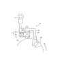
- FIG. 1 is a schematic diagram of an engine according to the present embodiment
- FIG. 1 is a schematic diagram of an ignition device for an engine according to the present embodiment
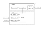
- FIG. 3 is a circuit block diagram of the ignition device 16
- FIG. 4 is a flowchart showing control processing when the internal combustion engine 2 is started.
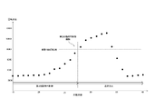
- 2 is a diagram showing an example of the relationship between the timing of checking the rotation speed of the internal combustion engine 2 when starting the internal combustion engine 2 and the rotation speed of the internal combustion engine 2.
- FIG. FIG. 4 is a diagram showing an example of conditions for canceling the first start-time PI control
- FIG. 10 is a diagram showing an example of conditions for canceling the second starting PI control;
- FIG. FIG. 2A is a vertical cross-sectional view showing the structure of the vaporizer 7, and
- FIG. 4B is a cross-sectional view showing the structure of the vaporizer 7.
- engine and a centrifugal clutch for transmitting the driving force of the engine to a driven device;
- a control device that adjusts the output of the engine, The engine is accelerated at start-up engine power capable of reaching a clutch-in rpm (the clutch-in rpm is usually the rpm at which the clutch is initiated) at start-up, and
- a simplified engine starting system is provided in which the control device has suppression control for suppressing the starting engine output to a rotation speed that does not exceed the clutch-in rotation speed.
- a simple engine starting system includes an engine, a centrifugal clutch, and a control device.
- the engine When starting the engine, the engine is accelerated with a starting engine output that can reach a rotation speed greater than the clutch-in rotation speed. For example, by controlling the amount of air and fuel supplied to the engine when the engine is started, a rotational speed higher than the clutch-in rotational speed can be reached.
- the suppression control suppresses the rotation speed to not exceed the clutch-in rotation speed.
- the starting operation of the engine can be simplified (no need for choke operation, etc.). can start the engine. In addition, it can be activated quickly, and can be ready for use in a short period of time.
- a second aspect is the first aspect, further comprising a throttle valve that adjusts the amount of intake air into the combustion chamber of the engine;
- the starting engine output is The throttle opening of the throttle valve is adjusted so that a rotational speed higher than the clutch-in rotational speed can be reached.
- a third aspect is the second aspect,
- the engine has an output of 0.5 kW to 2 kW, and the target of the throttle opening is a rotational speed equal to or higher than the clutch-in rotational speed and equal to or lower than twice the clutch-in rotational speed.
- a fourth aspect is the third aspect,
- the throttle opening is aimed at a rotational speed equal to or higher than the clutch-in rotational speed and 1.0 to 1.6 times the clutch-in rotational speed.
- a fifth aspect is the fourth aspect,
- the throttle opening is aimed at a rotational speed equal to or higher than the clutch-in rotational speed and 1.0 to 1.3 times the clutch-in rotational speed.
- a sixth aspect is, in the first to fifth aspects, Further comprising a detection unit that detects the rotation speed of the engine, The suppression control is This is feedback control that determines the ignition timing from the deviation between the target rotation speed and the detected rotation speed.
- the engine speed is detected and controlled based on the difference from the target speed, so the engine speed can be quickly increased and stabilized quickly.
- a seventh aspect is the sixth aspect, After the engine has started, the feedback control is started when at least one of the detected rotation speed, rotation speed, and time satisfies a predetermined condition.
- the feedback control is a first feedback control that performs feedback control so as to be within the first rotational speed range; and a second feedback control, after the first feedback control, for performing feedback control so that the engine speed falls within a second range of revolutions wider than the first range of revolutions.
- the second feedback control prepares the engine for rapid acceleration.
- a ninth aspect is any one of the first to eighth aspects, The engine is equipped with a manual rope pull recoil when activated.
- a ninth aspect is the ninth aspect, Equipped with a 2-stroke engine mounted on a hand-held blade work machine.
- ⁇ Eleventh Aspect>> further comprising a fuel valve that regulates the amount of fuel to the combustion chamber of the engine; The opening of the fuel valve is adjusted together with the throttle opening.
- FIG. 1 is a schematic diagram of an engine according to this embodiment.
- internal combustion engine 2 is preferably a two-stroke gasoline engine.
- the internal combustion engine 2 has a carburetor 7 .
- the carburetor 7 has a throttle valve (rotating portion 72 (see FIG. 8), which will be described later) that adjusts the amount of air-fuel mixture to be introduced into the internal combustion engine 2 .
- the throttle valve is operated by a throttle lever, choke knob (not shown) or the like.
- a conventionally known throttle valve can be used.
- the internal combustion engine 2 has a cylinder 2a, a crankshaft 2b, a piston 2c, and a spark plug 10.
- the piston 2c is arranged in the cylinder 2a and connected to the crankshaft 2b.
- the ignition plug 10 is arranged in the upper part of the cylinder 2a.
- the piston 2c rises to the top dead center position 2d.
- the ignition plug 10 is effectively operated to burn the air-fuel mixture in the cylinder 2a. Combustion of the air-fuel mixture imparts downward thrust to the piston 2c, producing torque in the crankshaft 2b.
- the internal combustion engine 2 can be mounted on a work machine or the like.
- the work machine can be, for example, an autonomous mowing robot, a hand-held work machine, or the like.
- the internal combustion engine 2 preferably has a recoil for manually pulling the rope when starting. By configuring in this way, even a person with relatively weak physical strength can easily start the device. Moreover, it is preferable to have a two-stroke engine mounted on a hand-held blade working machine. By configuring in this way, the engine can be easily started, and the engine can be started safely without clutch-in.
- the output of the internal combustion engine 2 is the work of the engine.
- the output of the internal combustion engine 2 is obtained by multiplying the torque by the rotation speed.
- the output of the internal combustion engine 2 is preferably 0.5 kW to 2 kW.
- the output of the internal combustion engine 2 is preferably 0.7 kW to 1.4 kW.
- FIG. 2 is a schematic diagram of an ignition device for the internal combustion engine 2 according to this embodiment.
- the internal combustion engine 2 has an ignition device 12 that activates a spark plug 10 .
- a flywheel 14a is attached to a crankshaft (not shown) of the internal combustion engine 2 so as to be interlockable.
- the ignition device 12 has a pair of magnets 14b, an iron core 14c, and an input coil 14d.
- a pair of magnets 14b are provided on the outer circumference of the flywheel 14a.
- the iron core 14c has a U-shape and is arranged adjacent to the outer circumference of the flywheel 14a.
- the input coil 14d is wound around the iron core 14c.
- the ignition device 12 has a control device 16, a primary coil 18a, and a secondary coil 18b.
- the control device 16 is connected to the input coil 14d.
- the primary coil 18 a is connected to the control device 16 .
- the secondary coil 18b is connected to the spark plug 10. As shown in FIG.
- FIG. 3 is a circuit block diagram showing the circuit configuration of the control device 16. As shown in FIG. As shown in FIG. 3 , the control device 16 has a capacitor 24 , a switching element 26 , a signal input circuit 32 , a microcomputer 20 , a power supply circuit 30 , a temperature sensor 50 and a temperature detection circuit 52 . 3, the primary coil 18a and the secondary coil 18b are shown as the ignition coil 18. As shown in FIG.
- the voltage induced in the input coil 14d is supplied to the microcomputer 20 from the IN1 terminal of the microcomputer 20 via the power supply circuit 30 as a power supply voltage.
- the power supply circuit 30 includes a rectifying circuit, a smoothing circuit, and the like (not shown). Thereby, a stable power supply voltage is supplied to the microcomputer 20 .
- the voltage induced in the input coil 14d is supplied to the microcomputer 20 from the IN2 terminal of the microcomputer 20 via the signal input circuit 32 as a control signal.
- the signal input circuit 32 includes a waveform shaping circuit (not shown). Thereby, a control signal is supplied to the microcomputer 20 .
- the control signal is a signal containing one or more pulses for each rotation of the crankshaft.
- the control signal functions as a reference signal for generating the ignition control signal.
- the microcomputer 20 detects or calculates the rotational speed (rotational speed) and angular position of the internal combustion engine 2 based on the control signal supplied via the signal input circuit 32 .
- the microcomputer 20 generates an ignition control signal based on the detection result and the calculation result, and outputs it to the switching element 26 from the OUT1 terminal.
- the switching element 26 is composed of, for example, a thyristor.
- the switching element 26 is connected to the OUT1 terminal of the microcomputer 20 .
- the switching element 26 is in a non-energized state.
- the switching element 26 is energized.
- a temperature sensor 50 detects the temperature of the internal combustion engine 2 and outputs a detection signal. Temperature sensor 50 is connected to temperature detection circuit 52 . The temperature detection circuit 52 supplies a detection signal to the microcomputer 20 . The detection signal is digitized by the temperature detection circuit 52 or the microcomputer 20 . The temperature detection circuit 52 is connected to the IN3 terminal of the microcomputer 20 . By doing so, the microcomputer 20 can acquire the temperature of the internal combustion engine 2 .
- FIG. 4 is a flowchart showing control processing when the internal combustion engine 2 is started. The processing shown in FIG. 4 is executed by the microcomputer 20 .
- FIG. 5 is a diagram showing an example of the relationship between the timing of checking the rotation speed of the internal combustion engine 2 in the starting mode of the internal combustion engine 2 and the rotation speed of the internal combustion engine 2 .
- FIG. 6 is a diagram showing an example of conditions for canceling the first start-up PI control.
- FIG. 7 is a diagram showing an example of conditions for canceling the second starting PI control.
- the microcomputer 20 determines whether or not the PI control transition condition is satisfied (step S411).
- the transition determination rotation speed is a rotation speed lower than the clutch-in rotation speed. By doing so, it is possible to shift to the first start-up PI control without clutch-in.
- the first start-up PI control is feedback control for stabilizing the rotation speed of the internal combustion engine 2 immediately after the engine starts. Specifically, the first start-up PI control controls the rotation speed of the internal combustion engine 2 within a first rotation speed range including the target rotation speed. By performing feedback control in this way, it is possible to control the rotational speed of the internal combustion engine 2 so as to quickly reach and maintain the target rotational speed.
- the first start-up PI control may be any control that allows the rotational speed of the internal combustion engine 2 to quickly reach and maintain the target rotational speed.
- the microcomputer 20 determines whether or not the conditions for ending the first start-up PI control are met.
- the condition for ending the first start-up PI control can be determined by the temperature of the internal combustion engine 2, the temperature deviation of the internal combustion engine 2, and the time (number of rotations) during which the first start-up PI control is being performed. Based on these, it can be determined whether or not the internal combustion engine 2 has stabilized immediately after starting. Other conditions may be used as long as the stability of the internal combustion engine 2 can be determined.
- the microcomputer 20 determines whether the temperature of the internal combustion engine 2 is equal to or higher than a predetermined temperature (step S415).
- the temperature of the internal combustion engine 2 can be detected by the temperature sensor 50 described above.
- the microcomputer 20 determines whether the temperature deviation is equal to or greater than a predetermined value. It is determined whether or not (step S417).
- the temperature deviation can be calculated from the difference between the temperature when the first start-time PI control is started and the temperature detected by the temperature sensor 50 this time.
- the microcomputer 20 determines whether timeout has occurred (whether a predetermined time has elapsed, or whether a predetermined time has elapsed). (Step S419).
- step S413 the process returns to step S413 to continue the first start-up PI control.
- the microcomputer 20 determines whether the temperature of the internal combustion engine 2 is equal to or higher than the predetermined temperature (YES) in the judgment processing of step S415, or determines whether the temperature deviation is equal to or higher than the predetermined value (YES) in the judgment processing of step S417, or If time-out has occurred (YES) in the determination process of 1), it is determined that the conditions for ending the first start-up PI control are satisfied, and the second start-up PI control is executed (step S421).
- the second start-up PI control is executed.
- the second start-up PI control can be executed.
- the second start-up PI control is control to prepare for acceleration after the rotation of the internal combustion engine 2 has been stabilized by the first start-up PI control. Specifically, it is a control that prepares for rapid acceleration of the internal combustion engine 2 according to the user's work.
- the second start-up PI control performs control so that the rotation speed of the internal combustion engine 2 is included in a second rotation speed range that is wider than the first rotation speed range of the first start-up PI control. By doing so, it is possible to increase the permissible range of the rotational speed of the internal combustion engine 2 and to respond to rapid acceleration.
- the second start-up PI control may be any control as long as the rotation speed of the internal combustion engine 2 is controlled within the second rotation speed range.
- the microcomputer 20 determines whether or not the conditions for ending the second start-up PI control are met.
- the conditions for ending the second start-up PI control can be determined according to the rotational speed of the internal combustion engine 2 and the acceleration state of the internal combustion engine 2 . With these, it is possible to respond to rapid acceleration according to the work of the user. Other conditions may be used as long as they can respond to rapid acceleration.
- the microcomputer 20 determines whether or not the rotation speed of the internal combustion engine 2 is equal to or higher than a predetermined rotation speed (step S423).
- the microcomputer 20 determines whether the internal combustion engine 2 is accelerating (step S425).
- the microcomputer 20 When the internal combustion engine 2 is not accelerating (NO), the microcomputer 20 returns the process to step S421 and continues the second starting PI control.
- the microcomputer 20 determines in step S411 that the condition for transition to PI control is not established (NO), and determines in step S423 that the rotation speed of the internal combustion engine 2 is equal to or higher than a predetermined rotation speed (YES). If it is determined in step S425 that the internal combustion engine 2 is accelerating (YES), the control shifts to normal ignition control (step S427), and this subroutine ends.
- FIG. 8A is a longitudinal sectional view showing the structure of the vaporizer 7, and a transverse sectional view showing the structure of the vaporizer 7.
- FIG. The vaporizer 7 according to this embodiment is a rotary throttle valve vaporizer.
- the carburetor 7 has an intake air flow rate control section 70 and a fuel flow rate control section 80 .
- the intake air flow control section 70 has a rotatable rotating section 72 .
- the rotating part 72 has a passage 74 through which air can pass.
- Passage 74 communicates with air supply hole 76 .
- Passage 74 communicates with the combustion chamber of internal combustion engine 2 . Air from outside is supplied to the combustion chamber from an air supply hole 76 through a passage 74 .
- the rotating part 72 rotates when the user operates the accelerator.
- the direction of the passage 74 is changed according to the rotation angle ⁇ of the rotating portion 72 to change the degree of overlap between the air supply hole 76 and the passage 74 .
- the degree of overlap controls the air flow rate.
- the air flow rate supplied to the combustion chamber of the internal combustion engine 2 can be adjusted by the rotation angle ⁇ of the rotating portion 72 .
- the rotating part 72 functions as a throttle valve.
- the opening of the throttle valve is aimed at a rotational speed equal to or higher than the clutch-in rotational speed and 1.0 to 1.6 times the clutch-in rotational speed. By doing so, it is possible to improve startability and suppress controllability. Further, it is more preferable to target the opening of the throttle valve to a rotational speed equal to or higher than the clutch-in rotational speed and 1.0 to 1.3 times the clutch-in rotational speed. By doing so, it is possible to further improve startability and suppression controllability.
- the fuel flow control section 80 has a movable needle 82 and a fuel nozzle 84 .
- the movable needle 82 can reciprocate vertically as the rotating portion 72 rotates.
- the movable needle 82 can be interlocked with the rotating portion 72 by an interlocking member 86 .
- the interlocking member 86 can be configured by a combination of cams having tapered surfaces, a combination of gears, or the like (not shown).
- the interlocking member 86 may be any member as long as it converts the rotational motion of the rotating portion 72 into the rectilinear motion of the movable needle 82 .
- the tip of the movable needle 82 is movably inserted into the fuel nozzle 84 .
- Fuel nozzles 84 supply fuel to the combustion chambers of internal combustion engine 2 .
- the air sucked into the combustion chamber through the passage 74 and the fuel discharged from the fuel nozzle 84 are mixed to form an air-fuel mixture, which is supplied to the combustion chamber of the internal combustion engine 2 .
- the depth of insertion into the fuel nozzle 84 is changed by reciprocating the movable needle 82 .
- the amount of fuel discharged from the fuel nozzle 84 can be adjusted, functioning as a fuel valve.
- the rotating part 72 and the movable needle 82 are interlocked by the interlocking member 86 .
- the interlocking member 86 can simultaneously adjust both the amount of air sucked into the combustion chamber from the passage 74 and the amount of fuel discharged from the fuel nozzle 84, thereby providing an optimal fuel flow according to the opening of the throttle valve. Air-fuel ratio can be set.
- the interlocking member 86 decreases the rotation angle ⁇ of the rotating portion 72, decreases the insertion depth of the movable needle 82, increases the rotation angle ⁇ of the rotating portion 72, and increases the insertion depth of the movable needle 82. depth gets deeper. That is, the amount of fuel can be increased by decreasing the depth of insertion of the movable needle 82 while increasing the amount of air by decreasing the rotation angle ⁇ of the rotating portion 72 (lift-up). Further, the amount of fuel can be reduced by increasing the insertion depth of the movable needle 82 while reducing the amount of air by increasing the rotation angle ⁇ of the rotating portion 72 .
- the throttle valve targets a rotation speed that is less than or equal to twice the clutch-in rotation speed.
- the opening degree of the throttle valve is 1.0 to 1.6 times the clutch-in rotational speed.
- the pattern of fuel flow rate control and suppression control by the ignition device according to the air amount can be simplified. For example, by incorporating retard control for an upper limit engine speed slightly higher than the clutch-in into suppression control by the ignition device, stable startability within a predetermined engine speed range and sustained stability after start-up can be achieved.
- the throttle valve opening is set as a target of 1.0 to 1.3 times the clutch-in rotational speed.
- the control of the fuel flow rate that is, the control of the amount of movement of the movable needle 82, can be minimized, resulting in quick and reliable startability.
- Complexity of the vaporizer body and peripheral components can be avoided while maintaining sustained stability after start-up.
- Such a configuration is suitable for a portable work machine with an engine output of 0.5 kW to 2 kW.
Landscapes
- Engineering & Computer Science (AREA)
- General Engineering & Computer Science (AREA)
- Mechanical Engineering (AREA)
- Chemical & Material Sciences (AREA)
- Combustion & Propulsion (AREA)
- Theoretical Computer Science (AREA)
- Signal Processing (AREA)
- Combined Controls Of Internal Combustion Engines (AREA)
Priority Applications (4)
| Application Number | Priority Date | Filing Date | Title |
|---|---|---|---|
| PCT/JP2021/016648 WO2022230023A1 (ja) | 2021-04-26 | 2021-04-26 | エンジン簡易起動システム |
| US18/554,632 US12577929B2 (en) | 2021-04-26 | 2021-04-26 | Easy engine starting system |
| JP2023516878A JP7738649B2 (ja) | 2021-04-26 | 2021-04-26 | エンジン簡易起動システム |
| EP21939186.9A EP4332369B1 (en) | 2021-04-26 | 2021-04-26 | ENGINE STARTING SYSTEM |
Applications Claiming Priority (1)
| Application Number | Priority Date | Filing Date | Title |
|---|---|---|---|
| PCT/JP2021/016648 WO2022230023A1 (ja) | 2021-04-26 | 2021-04-26 | エンジン簡易起動システム |
Publications (1)
| Publication Number | Publication Date |
|---|---|
| WO2022230023A1 true WO2022230023A1 (ja) | 2022-11-03 |
Family
ID=83846799
Family Applications (1)
| Application Number | Title | Priority Date | Filing Date |
|---|---|---|---|
| PCT/JP2021/016648 Ceased WO2022230023A1 (ja) | 2021-04-26 | 2021-04-26 | エンジン簡易起動システム |
Country Status (4)
| Country | Link |
|---|---|
| US (1) | US12577929B2 (https=) |
| EP (1) | EP4332369B1 (https=) |
| JP (1) | JP7738649B2 (https=) |
| WO (1) | WO2022230023A1 (https=) |
Citations (3)
| Publication number | Priority date | Publication date | Assignee | Title |
|---|---|---|---|---|
| JP2016079843A (ja) * | 2014-10-14 | 2016-05-16 | 株式会社やまびこ | エンジン駆動式作業機 |
| JP2018091353A (ja) * | 2016-11-30 | 2018-06-14 | 日立工機株式会社 | エンジン作業機 |
| JP2018204496A (ja) * | 2017-06-01 | 2018-12-27 | 株式会社やまびこ | エンジン作業機 |
Family Cites Families (14)
| Publication number | Priority date | Publication date | Assignee | Title |
|---|---|---|---|---|
| JPH041342Y2 (https=) * | 1984-09-05 | 1992-01-17 | ||
| JPH10131808A (ja) | 1996-10-29 | 1998-05-19 | Zama Japan Kk | 回転絞り弁式気化器 |
| JP2007046495A (ja) * | 2005-08-08 | 2007-02-22 | Honda Motor Co Ltd | 作業機用エンジンの回転数制御装置 |
| DE102012015034A1 (de) * | 2012-07-31 | 2014-02-27 | Andreas Stihl Ag & Co. Kg | Verfahren zur Abschaltung einer Drehzahlbegrenzung bei einem Verbrennungsmotor |
| CN104781525A (zh) * | 2012-11-14 | 2015-07-15 | 日立工机株式会社 | 发动机作业机 |
| DE102013005807A1 (de) * | 2013-04-04 | 2014-10-09 | Andreas Stihl Ag & Co. Kg | Verfahren zum Betrieb eines Verbrennungsmotors |
| DE102013009669B4 (de) | 2013-06-08 | 2022-01-05 | Andreas Stihl Ag & Co. Kg | Verbrennungsmotor mit einer Starteinrichtung |
| DE102013021832A1 (de) * | 2013-12-21 | 2015-06-25 | Andreas Stihl Ag & Co. Kg | Verfahren zum Betrieb eines handgeführten Arbeitsgeräts mit einem Verbrennungsmotor |
| JP6233018B2 (ja) * | 2013-12-27 | 2017-11-22 | 日立工機株式会社 | エンジン作業機 |
| JP6424956B2 (ja) * | 2015-04-28 | 2018-11-21 | 工機ホールディングス株式会社 | チェーンソー |
| JP2018091235A (ja) | 2016-12-02 | 2018-06-14 | 株式会社やまびこ | 携帯式エンジン作業機及びこれに組み込まれるロータリ式気化器 |
| DE102018002964A1 (de) * | 2017-09-15 | 2019-03-21 | Andreas Stihl Ag & Co. Kg | Handgeführtes Arbeitsgerät |
| JP7158936B2 (ja) | 2018-07-20 | 2022-10-24 | 株式会社やまびこ | 携帯式のエンジン作業機 |
| EP3604778B1 (de) * | 2018-08-03 | 2021-04-07 | Andreas Stihl AG & Co. KG | Verfahren zum starten eines verbrennungsmotors |
-
2021
- 2021-04-26 EP EP21939186.9A patent/EP4332369B1/en active Active
- 2021-04-26 WO PCT/JP2021/016648 patent/WO2022230023A1/ja not_active Ceased
- 2021-04-26 US US18/554,632 patent/US12577929B2/en active Active
- 2021-04-26 JP JP2023516878A patent/JP7738649B2/ja active Active
Patent Citations (3)
| Publication number | Priority date | Publication date | Assignee | Title |
|---|---|---|---|---|
| JP2016079843A (ja) * | 2014-10-14 | 2016-05-16 | 株式会社やまびこ | エンジン駆動式作業機 |
| JP2018091353A (ja) * | 2016-11-30 | 2018-06-14 | 日立工機株式会社 | エンジン作業機 |
| JP2018204496A (ja) * | 2017-06-01 | 2018-12-27 | 株式会社やまびこ | エンジン作業機 |
Non-Patent Citations (1)
| Title |
|---|
| See also references of EP4332369A4 * |
Also Published As
| Publication number | Publication date |
|---|---|
| JP7738649B2 (ja) | 2025-09-12 |
| JPWO2022230023A1 (https=) | 2022-11-03 |
| EP4332369B1 (en) | 2025-12-31 |
| EP4332369A4 (en) | 2025-03-05 |
| EP4332369A1 (en) | 2024-03-06 |
| US12577929B2 (en) | 2026-03-17 |
| US20240044309A1 (en) | 2024-02-08 |
Similar Documents
| Publication | Publication Date | Title |
|---|---|---|
| JP6313966B2 (ja) | 手で操縦される作業機における内燃エンジンの作動方法 | |
| JP5264328B2 (ja) | 2サイクルエンジンの作動方法 | |
| JP5818226B2 (ja) | エンジン及びエンジン作業機 | |
| CN102410095B (zh) | 可变气门正时机构的控制装置及控制方法 | |
| US8757121B1 (en) | Supplying supplementary fuel for engine startup | |
| RU2640145C2 (ru) | Способ управления числом оборотов двигателя внутреннего сгорания (варианты) | |
| JP7409914B2 (ja) | エンジンを備えた携帯作業機 | |
| EP1754878B1 (en) | Automatic choke control system for general-purpose engine | |
| EP0853189A2 (en) | Electronically controlled carburetor | |
| JP2015021498A (ja) | 内燃エンジンの作動方法 | |
| WO2022230023A1 (ja) | エンジン簡易起動システム | |
| JP7158936B2 (ja) | 携帯式のエンジン作業機 | |
| EP3237739B1 (en) | Internal combustion engine and method for safe starting the same | |
| WO2014002951A1 (ja) | 動力装置及びこれを備えた携帯作業機 | |
| US20130327307A1 (en) | 2-cycle engine and engine-powered working machine having the same | |
| JP3772366B2 (ja) | エンジン燃料供給制御システム及びそのエアブリード制御装置 | |
| EP1975395B1 (en) | General-purpose internal combustion engine | |
| JP2020084794A (ja) | 携帯式のエンジン作業機 | |
| JP5691500B2 (ja) | 小型エンジンおよびそれを備えたエンジン作業機 | |
| JP4144125B2 (ja) | 走行装置駆動用2サイクル内燃機関の回転方向切替制御方法 | |
| WO2013089599A1 (en) | Engine and a shut down method for an engine | |
| JP5640475B2 (ja) | 小型エンジンおよびそれを備えたエンジン作業機 | |
| JP2011256755A (ja) | 小型エンジンおよびそれを備えたエンジン作業機 | |
| JP2008255856A (ja) | エンジンの制御装置 | |
| JP2012057534A (ja) | 汎用エンジンの制御装置 |
Legal Events
| Date | Code | Title | Description |
|---|---|---|---|
| 121 | Ep: the epo has been informed by wipo that ep was designated in this application |
Ref document number: 21939186 Country of ref document: EP Kind code of ref document: A1 |
|
| WWE | Wipo information: entry into national phase |
Ref document number: 18554632 Country of ref document: US |
|
| WWE | Wipo information: entry into national phase |
Ref document number: 2023516878 Country of ref document: JP |
|
| WWE | Wipo information: entry into national phase |
Ref document number: 2021939186 Country of ref document: EP |
|
| NENP | Non-entry into the national phase |
Ref country code: DE |
|
| ENP | Entry into the national phase |
Ref document number: 2021939186 Country of ref document: EP Effective date: 20231127 |
|
| WWG | Wipo information: grant in national office |
Ref document number: 2021939186 Country of ref document: EP |
|
| WWG | Wipo information: grant in national office |
Ref document number: 18554632 Country of ref document: US |