WO2022224712A1 - 搬送装置及び保管装置 - Google Patents
搬送装置及び保管装置 Download PDFInfo
- Publication number
- WO2022224712A1 WO2022224712A1 PCT/JP2022/014656 JP2022014656W WO2022224712A1 WO 2022224712 A1 WO2022224712 A1 WO 2022224712A1 JP 2022014656 W JP2022014656 W JP 2022014656W WO 2022224712 A1 WO2022224712 A1 WO 2022224712A1
- Authority
- WO
- WIPO (PCT)
- Prior art keywords
- medicine box
- unit
- medicine
- transport
- conveying
- Prior art date
- Legal status (The legal status is an assumption and is not a legal conclusion. Google has not performed a legal analysis and makes no representation as to the accuracy of the status listed.)
- Ceased
Links
Images


Classifications
-
- A—HUMAN NECESSITIES
- A61—MEDICAL OR VETERINARY SCIENCE; HYGIENE
- A61J—CONTAINERS SPECIALLY ADAPTED FOR MEDICAL OR PHARMACEUTICAL PURPOSES; DEVICES OR METHODS SPECIALLY ADAPTED FOR BRINGING PHARMACEUTICAL PRODUCTS INTO PARTICULAR PHYSICAL OR ADMINISTERING FORMS; DEVICES FOR ADMINISTERING FOOD OR MEDICINES ORALLY; BABY COMFORTERS; DEVICES FOR RECEIVING SPITTLE
- A61J3/00—Devices or methods specially adapted for bringing pharmaceutical products into particular physical or administering forms
-
- B—PERFORMING OPERATIONS; TRANSPORTING
- B65—CONVEYING; PACKING; STORING; HANDLING THIN OR FILAMENTARY MATERIAL
- B65G—TRANSPORT OR STORAGE DEVICES, e.g. CONVEYORS FOR LOADING OR TIPPING, SHOP CONVEYOR SYSTEMS OR PNEUMATIC TUBE CONVEYORS
- B65G1/00—Storing articles, individually or in orderly arrangement, in warehouses or magazines
- B65G1/02—Storage devices
- B65G1/04—Storage devices mechanical
-
- B—PERFORMING OPERATIONS; TRANSPORTING
- B65—CONVEYING; PACKING; STORING; HANDLING THIN OR FILAMENTARY MATERIAL
- B65G—TRANSPORT OR STORAGE DEVICES, e.g. CONVEYORS FOR LOADING OR TIPPING, SHOP CONVEYOR SYSTEMS OR PNEUMATIC TUBE CONVEYORS
- B65G47/00—Article or material-handling devices associated with conveyors; Methods employing such devices
- B65G47/22—Devices influencing the relative position or the attitude of articles during transit by conveyors
- B65G47/24—Devices influencing the relative position or the attitude of articles during transit by conveyors orientating the articles
- B65G47/244—Devices influencing the relative position or the attitude of articles during transit by conveyors orientating the articles by turning them about an axis substantially perpendicular to the conveying plane
-
- B—PERFORMING OPERATIONS; TRANSPORTING
- B65—CONVEYING; PACKING; STORING; HANDLING THIN OR FILAMENTARY MATERIAL
- B65G—TRANSPORT OR STORAGE DEVICES, e.g. CONVEYORS FOR LOADING OR TIPPING, SHOP CONVEYOR SYSTEMS OR PNEUMATIC TUBE CONVEYORS
- B65G47/00—Article or material-handling devices associated with conveyors; Methods employing such devices
- B65G47/22—Devices influencing the relative position or the attitude of articles during transit by conveyors
- B65G47/26—Devices influencing the relative position or the attitude of articles during transit by conveyors arranging the articles, e.g. varying spacing between individual articles
- B65G47/28—Devices influencing the relative position or the attitude of articles during transit by conveyors arranging the articles, e.g. varying spacing between individual articles during transit by a single conveyor
- B65G47/29—Devices influencing the relative position or the attitude of articles during transit by conveyors arranging the articles, e.g. varying spacing between individual articles during transit by a single conveyor by temporarily stopping movement
-
- B—PERFORMING OPERATIONS; TRANSPORTING
- B65—CONVEYING; PACKING; STORING; HANDLING THIN OR FILAMENTARY MATERIAL
- B65G—TRANSPORT OR STORAGE DEVICES, e.g. CONVEYORS FOR LOADING OR TIPPING, SHOP CONVEYOR SYSTEMS OR PNEUMATIC TUBE CONVEYORS
- B65G47/00—Article or material-handling devices associated with conveyors; Methods employing such devices
- B65G47/74—Feeding, transfer, or discharging devices of particular kinds or types
- B65G47/88—Separating or stopping elements, e.g. fingers
Definitions
- the present invention relates to a transport device that transports medicine boxes containing medicines, and a storage device that stores the medicine boxes transported by the transport equipment.
- Patent Literature 1 includes a storage shelf capable of storing pharmaceuticals, an input unit having a belt conveyor, and a robot arm for receiving the pharmaceuticals input from the input unit.
- the user is required to place the medicine at a predetermined position inside the entrance when inserting the medicine from the entrance. This is because the storage device acquires, for example, the size information of the medicine at a predetermined position.
- a label is attached by the label attaching unit to the medicine conveyed by the belt conveyor.
- the label attaching unit is provided corresponding to a position where the medicine is conveyed from a predetermined position to the inside of the storage device by the belt conveyor. From this point of view as well, the user is required to place the medicine at a predetermined position. Therefore, when putting medicines into the storage device of Patent Literature 1, the user may be burdened with placing them in a predetermined position.
- Patent Document 1 does not mention a method for determining the placement position of a drug when arranging a plurality of drugs in the depth direction of the storage shelf.
- a conveying device includes a receiving portion for receiving a drug box containing a drug, and a contact surface with which one side of the drug box received by the receiving portion contacts.
- a side contact portion having a side contact portion;
- a first conveying portion that conveys the medicine box received by the receiving portion to the side contact portion in a state of being placed thereon and brings one side of the medicine box into contact with the contact surface;
- a second conveying unit that grips the medicine box after contacting the surface and conveys it to a storage rack that stores the medicine box.
- a transport device includes a receiving unit that receives a medicine box containing a medicine, a medicine box received by the receiving unit, and a storage unit that stores the medicine box.
- a conveying unit that conveys and stores the drug to a storage shelf that stores the second drug box, and a second drug box having a width equal to or less than the width of the first drug box is newly placed at a position of the storage shelf where the first drug box is stored.
- the transport unit can store the second medicine box side by side in the depth direction of the first medicine box and the storage shelf.
- the present invention it is possible to reduce the burden on the user who stores medicine boxes. Moreover, according to one aspect of the present invention, it is possible to improve the dispensing efficiency of the medicine box.
- FIG. 10 is a diagram showing an example of a process in which the medicine box placed on the first transport section is transported to the 3-1 transport section; It is a figure which shows an example of the process of adjusting direction of the medicine box received by the medicine receiving part.
- FIG. 10 is a diagram showing an operation example when the second transport unit pulls out and grips the drug box on the third transport unit, and an operation example when the drug box gripped by the second transport unit is pushed out and stored in the storage rack; be.
- FIG. 10 is a diagram showing an operation example of the second conveying unit when taking out only the medicine box located on the far side of the storage shelf as a conveying target.
- FIG. 10 is a diagram showing another example of the operation of the second transport section when taking out only the medicine box located on the back side of the storage shelf; It is a perspective view which shows an example of a structure of a 5th conveyance part. It is a figure which shows the example of arrangement
- FIG. 4 is a perspective view showing an example of the configuration of a slide portion; It is a side sectional view of a slide part.
- FIG. 10 is a diagram showing an example of a process in which the medicine box placed on the first transport section is transported to the 3-1 transport section;
- FIG. 11 is a perspective view showing an example of the appearance of a storage device according to still another embodiment; It is a perspective view which shows the figure which shows the state which removed some outer walls of the storage apparatus.
- 3 is a block diagram showing an example of the configuration of a storage device;
- FIG. It is a perspective view which shows an example of a structure of a lift. It is a figure which shows the structure of top surface part vicinity of a storage apparatus.
- FIG. 4 is a side view showing an example of the configuration of a robot arm;
- FIG. 10 is a diagram showing an example of a process in which the medicine box placed on the first transport section is transported to the 3-1 transport section;
- FIG. 11 is a perspective view showing an example of the appearance of a storage device according to still another embodiment; It is a perspective view which shows the figure which shows the state which removed some outer walls of the
- FIG. 10 is a view showing an example of lift operation when pulling out a container that has been thrown into the container receiving section; It is a figure which shows the operation example of a robot arm and a mounting base.
- FIG. 10 is a diagram showing an operation example of the robot arm when causing the reading unit to read the medicine identification information;
- FIG. 10 is a diagram showing an example of the operation of the robot arm when laying down the medicine box on the mounting table; It is a figure which shows the example of the image of the container imaged by the imaging part.
- FIG. 10 is a diagram showing an operation example of the robot arm after reading of drug identification information is completed; It is a figure which shows an example of the reception image which receives the dispensing instruction
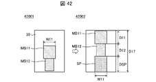
- FIG. 10 is a conceptual diagram for explaining the process of determining whether or not the drug boxes to be stored can be stored in one row in the depth direction of the storage shelf with respect to one drug box stored in the storage shelf.
- FIG. 10 is a diagram for explaining an operation example of the gripping section of the second transport section when storing a medicine box to be stored in line with the medicine boxes when a plurality of medicine boxes are stored in the storage shelf; .
- FIG. 10 is a conceptual diagram for explaining the process of determining whether or not a medicine box to be stored can be stored in a row together with a plurality of medicine boxes stored on a storage shelf.
- FIG. 1 is a diagram showing an example of a drug dispensing system 100.
- a drug dispensing system 100 is a system capable of dispensing drugs, and includes a storage device 1 and a drug station 2, as shown in FIG. 1, for example.
- the drug station 2 is a device for storing drugs and for filling and dispensing drugs.
- the drag station 2 has, for example, a main unit 201 and a picking unit 202 .
- the main unit 201 is a unit that stores medicine. Specifically, the main unit 201 functions as a medicine storage shelf capable of storing a plurality of cassettes (not shown) containing medicines.
- the main unit 201 can store types (eg, about 1,500 to 2,000 types) of medicines that are expected to be used in one facility such as a hospital or a pharmacy.
- Drugs include, for example, tablets, powders, external drugs such as ointments and eye drops, and injection drugs.
- the main unit 201 may store any drug regardless of the form of the drug container (eg, PTP (Press Through Package) sheet, bottle, tube, bottle, etc.).
- medicines may be stored in the body unit 201 in the form of medicine boxes containing the medicines described above.
- the picking unit 202 is a device that enables the operator to handle medicines stored in the main unit 201. In order to realize drug dispensing, the picking unit 202 functions as a device for an operator to pick out the required number of drugs from the cassette. The picking unit 202 also functions as a device for a worker to perform a filling operation for filling a cassette stored in the main unit 201 with medicine. In other words, the picking unit 202 functions as a device for the operator to take out drugs from cassettes stored in the main unit 201 or to fill the cassettes with drugs.
- the picking unit 202 is provided on the front side of the main unit 201 along the width direction ( ⁇ X-axis direction) of the main unit 201 .
- the present invention is not limited to this, and one picking unit 202 may be provided, or three or more picking units 202 may be provided.
- the drug station 2 sequentially transfers the cassettes stored in the main unit 201 to the picking unit 202 based on prescription data, for example.
- An operator at the drug station 2 takes out the drug from the cassette transferred to the picking unit 202 and puts it into a carrier tray (not shown). Medicines accommodated in the transport tray are subject to visual inspection by medical professionals such as pharmacists.
- the storage device 1 is a device that stores medicine boxes containing medicines.
- the storage device 1 stores medicine boxes that the operator of the storage device 1 puts into the medicine receiving part 11 (receiving part).
- the storage device 1 stores, for example, drug boxes containing drugs that can be handled at the drug station 2. For example, when a drug of a certain type is out of stock at the drug station 2 , the storage device 1 sends a drug box containing the drug stored in the storage device 1 to the drug station 2 . put out.
- the storage device 1 includes a fifth transport section 19 that transports stored medicine boxes to the drug station 2 .
- the fifth transport section 19 is, for example, a belt conveyor.
- the fifth transport section 19 includes a discharge transport section 192 .
- the discharging/conveying unit 192 is a conveying unit that discharges the medicine boxes stored in the storage device 1 from the storage device 1 .
- the storage device 1 also includes an input box 40 into which the medicine boxes transported by the fifth transport unit 19 are input.
- the discharge transport section 192 and the input box 40 are provided on the front side of the main unit 201 and above the picking unit 202 .
- the input box 40 is provided below the discharge transport section 192 .
- the input box 40 is provided corresponding to each picking unit 202 .
- the medicine box transported by the discharge transport unit 192 is transported to the designated input box 40 and dropped at the input box 40 .
- Designation of the input box 40 to which the medicine box is to be transported is performed by the drug station 2, for example, and the control unit 21 (see FIG. , transports the drug box to the specified input box 40. - ⁇ Note that the delivery destination of the medicine box may be input via the touch panel 20 .
- the operator at the drug station 2 can receive the medicine box transported from the storage device 1. Then, the operator of the drug station 2 can fill the drug station 2 with the received drug box or the drug contained in the drug box in the picking unit 202 . In addition, the operator of the drug station 2 can store the received drug stored in the drug box in the picking unit 202 in a transport tray (not shown) as the drug to be dispensed from the drug station 2 .
- the input box 40 does not necessarily have to be provided corresponding to the picking unit 202 .
- the input box 40 may be provided in common for at least two picking units 202 . Moreover, even when only one picking unit 202 is provided, the input box 40 may not be provided corresponding to the picking unit 202 .
- each picking unit 202 takes out the drug from the cassette transferred to the picking unit 202 or fills the cassette with the drug.
- the operator of the drug station 2 in front of each picking unit 202, takes out the drug from the cassette transferred to the picking unit 202 or fills the cassette with the drug.
- the efficiency of the medicine taking-out operation and the filling operation can be improved.
- the operators of the drug station 2 and the storage device 1 take out drugs from the drug station 2 and are unqualified persons who are not qualified as pharmacists, nurses, doctors, or the like. However, the worker may be a qualified person who has the relevant qualification.
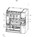
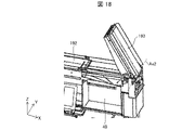
- FIG. 2 is a diagram showing an example of the appearance of the storage device 1.
- Reference numeral 2001 in FIG. 2 indicates an example of the appearance of the storage device 1 when the first door 51 and the second door 52 are closed, and reference numeral 2002 indicates the first door 51 and the second door 52 are open.
- 1 shows an example of the appearance of the storage device 1 in this case.
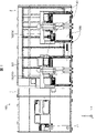
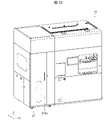
- FIG. 3 is a diagram showing an example of the internal structure of the storage device 1. As shown in FIG.
- the storage device 1 includes a touch panel 20, a first door 51, and a second door 52.
- the touch panel 20 is a display device that displays various information about the storage device 1 and also functions as an input device that receives input operations by the operator.
- the first door 51 is a door that can block the access of the operator to the medicine receiving section 11.
- the first door 51 is a shutter that can slide vertically upward (+Z-axis direction).
- the first door 51 may be locked by a lock mechanism (not shown) when closed.
- the control unit 21 see FIG. 4
- the operator can open the first door 51 .
- the first door 51 By providing the first door 51 , the first door 51 can be closed when the operator does not put the medicine box into the medicine receiving part 11 . Therefore, it is possible to reduce the possibility that the operator carelessly puts his/her hand into the medicine receiving portion 11 . That is, the safety of the storage device 1 can be enhanced. For example, in the later-described storage device 1B, it is possible to reduce the possibility of a worker touching the first transport section 112 in operation when performing automatic filling.
- the second door 52 is a door that allows the worker to access the interior of the storage device 1 .
- the second door 52 is a shutter that can slide vertically downward ( ⁇ Z axis direction).
- the second door 52 may be locked by a lock mechanism (not shown) when closed.
- the control unit 21 receives an input for unlocking the second door 52 via the touch panel 20 when a medicine box transport error occurs inside the storage device 1 (for example, when the medicine box is jammed). is received, the lock by the lock mechanism is released. This allows the operator to open the second door 52 .
- the operator can visually recognize the third transport section 15 and the fifth transport section 19 inside the storage device 1. Therefore, for example, when the medicine boxes are clogged in the third conveying section 15 and the fifth conveying section 19, the operator can remove the medicine boxes to resume filling the storage device 1 with the medicine boxes. It becomes possible.
- the storage device 1 includes a drug receiving section 11, a third transport section 15, a fifth transport section 19, and a storage shelf 30.
- the medicine receiving part 11 is a part that receives the medicine box inserted by the operator.
- the medicine receiving section 11 is provided with a first conveying section 112 and a shutter 114 .
- the first conveying section 112 conveys the medicine box received by the medicine receiving section 11 to the shutter 114 in a state where the medicine box is placed.
- the shutter 114 prevents the medicine box from moving while the first transport section 112 is transporting it toward the second transport section 17 (see FIG. 11).
- the storage shelf 30 is a shelf for storing medicine boxes.
- at least one storage shelf 30 can be installed in a first storage 31A provided on the front side of the storage device 1 and a second storage 31B provided on the back side of the storage device 1.
- the first storage 31A is provided above the fifth transport section 19 and below the drug receiving section 11 and the third transport section 15 .
- the second storage 31B is provided on one surface of the storage device 1 on the back side. 3 shows only the case where one storage shelf 30 is provided above the fifth transport section 19 and one storage shelf 30 is provided below the medicine receiving section 11 and the third transport section 15.
- a plurality of storage racks 30 can be installed in the storage 31A and the second storage 31B.
- a plurality of drug boxes may be arranged in the storage shelf 30 in the depth direction ( ⁇ Y-axis direction) of the storage device 1 .
- at least two of the plurality of medicine boxes may be medicine boxes of the same kind or different kinds.
- the number of medicine boxes stored in a row in the depth direction of the storage device 1 may be determined according to the length of the storage shelf 30 in the depth direction and the length of the medicine boxes.
- a medicine box put into the medicine receiving part 11 is conveyed to the third conveying part 15 by the first conveying part 112 when the shutter 114 is in the open state.
- the third conveying unit 15 sequentially receives the medicine boxes conveyed from the first conveying unit 112, and conveys the received medicine boxes while being spaced apart by a predetermined width.
- the second transport unit 17 grips the medicine box placed on the third transport unit 15 and transports it to the storage shelf 30 .
- the drug box put into the drug receiving section 11 can be stored in the storage shelf 30 .
- the second transport unit 17 grips the medicine box stored in the storage shelf 30 and transports it to the fifth transport unit 19 .
- the medicine boxes stored in the storage shelf 30 can be transported from the storage device 1 to another device (the drug station 2 in this embodiment).
- FIG. 4 is a block diagram showing an example of the configuration of the storage device 1. As shown in FIG. 4 , the white arrows indicate the flow from the medicine box received in the medicine receiving unit 11 until it is stored in the storage shelf 30, and after the medicine box is stored in the storage shelf 30, it is placed in the input box 40. and the flow until it is discharged. FIG. 4 shows only the main configuration for explaining the flow of the medicine box.
- the storage device 1 includes, for example, a medicine receiving portion 11, a width detecting portion 13, a third conveying portion 15, a second conveying portion 17, a fifth conveying portion 19, a control portion 21, a storage portion 23, and a pop-out detecting portion 25.
- a medicine receiving portion 11 includes, for example, a medicine receiving portion 11, a width detecting portion 13, a third conveying portion 15, a second conveying portion 17, a fifth conveying portion 19, a control portion 21, a storage portion 23, and a pop-out detecting portion 25.
- a medicine receiving portion 11 includes, for example, a medicine receiving portion 11, a width detecting portion 13, a third conveying portion 15, a second conveying portion 17, a fifth conveying portion 19, a control portion 21, a storage portion 23, and a pop-out detecting portion 25.
- Specific configurations other than the control unit 21 and the storage unit 23 will be described with reference to drawings other than FIG. 4 .
- the control unit 21 comprehensively controls the storage device 1 (specifically, the transport device 10).
- the storage unit 23 stores information necessary for controlling the storage device 1 (specifically, the transport device 10).
- the control unit 21 includes, for example, a transport control unit 211, a shutter control unit 212, a direction identification unit 213, a storage position management unit 214, and a touch panel control unit 215.
- the transport control unit 211 controls the operations of the first transport unit 112, the third transport unit 15, the second transport unit 17, and the fifth transport unit 19.
- the shutter control unit 212 controls opening and closing operations of the shutter 114 .
- the touch panel control unit 215 controls display on the touch panel 20 .
- the direction specifying unit 213 specifies the direction of the medicine box based on the detection result of the first detection unit 113.
- the orientation identifying unit 213 identifies the orientation of the medicine box based on the detection result of the first detecting unit 113 and the medicine identification information read by the reading unit 111 .
- the direction specifying unit 213 determines whether or not the medicine is oriented in a predetermined direction. In this embodiment, the direction specifying unit 213 determines whether or not the longitudinal direction of the medicine box faces the depth direction of the storage device 1 .
- the transport control unit 211 determines that the medicine box specified by the direction specifying unit 213 is not oriented in the predetermined direction, the transport control unit 211 operates the first transport unit 112 for a predetermined time while the shutter 114 is closed.
- the medicine identification information is information attached to the surface of the medicine box for identifying the medicine contained in the medicine box (eg, information indicating the type of medicine).
- the medicine identification information is an example of information included in the GS1 code, for example, and is attached to the surface of the medicine box in the form of a bar code.
- the medicine identification information may be any information that can identify the medicine contained in the medicine box, and may be realized by information other than the GS1 code.
- the medicine identification information may be in a format readable by the reading unit 111, and may be attached in a format other than a barcode.
- the information attached to the surface of the medicine box may include medicine identification information indicating the type of medicine, as well as information indicating the expiration date, lot number, and number of medicines stored in the medicine box. Note that the expiration date may also be referred to as the expiration date.
- the longitudinal direction of the medicine box is the direction along the longest side of the sides defining the medicine box
- the short direction of the medicine box is the direction along the shortest side of the sides defining the medicine box. direction.
- the shape of the medicine box is a substantially rectangular parallelepiped.
- the storage position management section 214 manages the storage position in the storage shelf 30 of the medicine box received by the medicine receiving section 11 .
- the storage position management unit 214 specifies the size of the medicine box received by the medicine receiving unit 11, for example, by referring to the medicine database stored in the storage unit 23 based on the medicine identification information read by the reading unit 111. do.
- Storage position management unit 214 determines the storage position of the medicine box in storage shelf 30 based on the specified size of the medicine box and the storage position information stored in storage unit 23 .
- a drug database manages information on multiple types of drugs.
- the drug database manages, for example, information indicating the size (eg, length, width, and height) of a drug box containing a drug in association with each of a plurality of types of drugs.
- the storage position information is information indicating the storage position of the drug (specifically, the drug box) in the storage shelf 30 .
- the storage location management unit 214 can identify the empty area in the storage shelf 30 by referring to the storage location information.
- the storage position management unit 214 updates the storage position information, for example, when the storage position of the medicine box is determined and when an instruction to take out the medicine box is received.
- the storage position management section 214 may update the storage position information so as to include the storage position of the medicine box.
- the storage position management unit 214 may update the storage position information so as to delete the storage position of the medicine box (to make it an empty area).
- Storage location information may be updated. For example, when the storage position management unit 214 receives a detection signal indicating that a medicine box has been detected from the passage detection unit 1751 (see FIG. 11) provided in the grip unit 171 of the second transport unit 17, the storage position management unit 214 stores the storage position information. By referring to it, it is determined whether the medicine box has been stored or taken out. The storage location management unit 214 may update the storage location information based on this determination result.
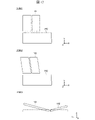
- Reference numerals 5001 and 5002 in FIG. 5 are perspective views showing an example of the configuration of the medicine receiving portion 11 and its surroundings.
- the arrow at reference numeral 5001 in FIG. 5 indicates the transport direction of the medicine box in the third transport section 15 .
- FIG. 6 is a perspective view showing an example of the drug receiving portion 11. As shown in FIG.
- the medicine receiving portion 11 is a space formed by a first side wall portion 116, a second side wall portion 117, a shutter 114, a first conveying portion 112, and a top surface portion 118. Further, the first side wall portion 116 , the shutter 114 , the first conveying portion 112 and the top surface portion 118 form an opening for receiving the medicine box in the medicine receiving portion 11 .
- the first side wall portion 116 is a side wall portion facing the shutter 114 .
- the second side wall portion 117 is a side wall portion facing the opening. Further, the shutter 114 functions as part of the side wall of the drug receiving portion 11 , and the first conveying portion 112 functions as the bottom portion of the drug receiving portion 11 .
- a reading part 111 for reading medicine identification information attached to the surface of the medicine box there is provided a reading part 111 for reading medicine identification information attached to the surface of the medicine box.
- the medicine identification information is attached to the surface of the medicine box in the form of a bar code. Therefore, in this embodiment, the reading unit 111 is a barcode reader.
- the reading unit 111 may be any device capable of reading the medicine identification information attached to the surface of the medicine box.
- the reading unit 111 transmits the read drug identification information to the control unit 21 .
- the control unit 21 causes the notification unit (not shown) to output a sound (eg, BEEP sound). That is, the control unit 21 causes the notification unit to notify that the reading unit 111 has read the medicine identification information.
- a sound eg, BEEP sound
- the control unit 21 causes the notification unit to notify that the reading unit 111 has read the medicine identification information.
- the operator can put the next medicine box into the medicine receiving part 11 and cause the reading part 111 to read the medicine identification information attached to the medicine box. That is, the storage device 1 can continuously receive medicine boxes in the medicine receiving section 11 .
- control unit 21 may drive the reading unit 111 when receiving an input for manual filling via the touch panel 20 .
- a plurality of reading units 111 are provided inside the medicine receiving unit 11 .
- reading units 111A to 111C are provided as shown in FIG.
- the reading portion 111A is provided on the first side wall portion 116 so that the reading direction of the medicine identification information is substantially orthogonal to the second side wall portion 117 .
- the reading portion 111B is provided on the second side wall portion 117 so that the reading direction of the medicine identification information is substantially orthogonal to the first side wall portion 116 .
- Reading unit 111 ⁇ /b>C is provided on top surface 118 so that the medicine identification information can be read in a direction substantially perpendicular to top surface 118 .
- only one reading unit 111 may be provided near the medicine receiving unit 11 in the housing of the storage device 1 . Even in this case, the reading unit 111 can read the medicine identification information attached to the medicine box. However, in this case, in order for the reading unit 111 to read the medicine identification information, the operator confirms where the barcode is attached to the medicine box, and then reads the barcode-attached surface. It is necessary to turn to the 111 side.
- the barcode attached to the medicine box is relatively small compared to the medicine box, and the position of the barcode is different for each manufacturer. Therefore, it may be a burden for the operator to check which position of the medicine box the barcode is attached. In addition, if confirmation takes time, the efficiency of the medicine box storage operation will be reduced accordingly.
- the reading unit 111 can read the drug identification information. Also, as described above, the operator can confirm whether or not the medicine identification information has been read. Therefore, the operator can cause the reading unit 111 to read the medicine identification information simply by rotating the medicine box until a sound is output without being conscious of the position of the barcode on the medicine box. Therefore, it is possible to reduce the burden on the operator and reduce the possibility that the efficiency of the storage work will be lowered.
- the reading units 111A to 111C when the reading units 111A to 111C are provided so that the reading directions of the reading units 111A to 111C are orthogonal to each other, as in the present embodiment, the reading units 111A to 111C read the medicine box inserted inside the medicine receiving unit 11. It is possible to simultaneously irradiate reading light from three mutually orthogonal directions. Therefore, it is possible to further improve the reading efficiency of the medicine identification information. However, if a plurality of reading units 111 are provided in the drug receiving unit 11, the burden on the operator for reading the drug identification information can be reduced.
- the first transport unit 112 transports the medicine box received by the medicine receiving unit 11 to the shutter 114 while it is placed thereon.
- the 1st conveyance part 112 is a belt conveyor.
- the transport control unit 211 causes the first transport unit 112 to forward after receiving the medicine identification information read by the reading unit 111 .
- Forward feeding of the first conveying unit 112 means operating the conveying belt of the first conveying unit 112 to convey the placed medicine box toward the shutter 114 (+X-axis direction).
- the first transport control unit 211 operates the transport belt of the first transport unit 112 to transport the placed medicine box toward the first side wall unit 116 ( ⁇ X axis direction). It is also referred to as reversing the conveying unit 112 .
- the shutter 114 is provided between the first transport section 112 and the third transport section 15 and is opened and closed under the control of the shutter control section 212 .
- the shutter 114 is closed when the medicine receiving portion 11 can receive the medicine box. Further, the shutter 114 prevents movement of the medicine box transported to the third transporting part 15 side by the first transporting part 112 in the closed state.
- the shutter 114 functions as a side contact portion having a side surface 1141 (contact surface) with which one side surface of the medicine box being conveyed by the first conveying portion 112 contacts. That is, in the present embodiment, the first transport section 112 transports the medicine box received by the medicine receiving part 11 so that one side surface of the medicine box is brought into contact with the side surface 1141 .
- the shutter 114 performs opening and closing operations in the vertical direction ( ⁇ Z-axis direction).
- the first detection unit 113 is a detection unit that detects a medicine box that is in contact with or close to the shutter 114 .
- the first detection unit 113 includes a plurality of sensors 1131 that detect the presence or absence of an object by outputting light.
- the plurality of sensors 1131 are provided along one side included in the side surface 1141 of the shutter 114 and capable of contacting the first conveying unit 112, as indicated by reference numeral 5001 in FIG. It is That is, the plurality of sensors 1131 are provided along the ⁇ Y-axis direction at the lower end of the side surface 1141 .
- a plurality of sensors 1131 are provided on the side surface 1141 of the shutter 114 so as to emit light in a direction substantially perpendicular to the side surface 1141 of the shutter 114 .
- the sensor 1131 is a reflective sensor that includes an emitting portion that emits light and a light receiving portion that receives the reflected light after the emitted light is reflected by the object.
- the first detection unit 113 transmits to the control unit 21 a detection signal indicating that the medicine box has been detected. Further, the first detection unit 113 includes information indicating which sensor 1131 among the plurality of sensors 1131 has detected the medicine box in the detection signal and transmits the detection signal to the control unit 21 . Thereby, the control unit 21 can determine whether or not the medicine box is detected. Further, the direction specifying unit 213 compares the arrangement position of the sensor 1131 that detects the medicine box with the size of the medicine box obtained by referring to the medicine database based on the medicine identification information read by the reading unit 111. . Thereby, the direction specifying unit 213 can specify which surface of the medicine box is close to or in contact with the side surface 1141 of the shutter 114 . Therefore, the direction identifying unit 213 can identify whether or not the medicine box that is close to or in contact with the side surface 1141 of the shutter 114 is oriented in a predetermined direction.
- the first detection unit 113 only needs to be able to identify how the medicine box is in contact with the side surface 1141 of the shutter 114 .
- the plurality of sensors 1131 may be provided in a plurality of rows, or may emit electromagnetic waves other than light or sound waves (eg, ultrasonic waves).
- the first detection unit 113 may be an imaging unit provided on the top surface 118 adjacent to the shutter 114 .
- the orientation identification unit 213 can identify the orientation of the medicine box by analyzing the image of the medicine box captured by the imaging unit. That is, the direction specifying unit 213 can specify the direction of the medicine box based on the detection result of the first detection unit 113 as an imaging unit.
- the entrance/exit detector 115 is provided in the medicine receiving part 11 on the front side of the first transport part 112 (on the medicine box receiving side).
- the entrance/exit detection unit 115 includes a plurality of sensors that detect the presence or absence of an object by outputting light.
- the plurality of sensors are arranged in a row in the ⁇ X-axis directions.
- the sensor is a reflective sensor.
- the control unit 21 When the sensor detects an object, it transmits a detection signal indicating that the object has been detected to the control unit 21 . Thereby, the control unit 21 can determine whether or not the operator's hand and arm are inserted into the medicine receiving unit 11 . Therefore, the shutter control unit 212 does not operate the shutter 114 when the operator's hand and arm are inserted into the medicine receiving part 11, and the operator's hand and arm are not inserted into the medicine receiving part 11. The shutter 114 can be operated only when Therefore, it is possible to reduce the possibility of an accident in which the operator's hand and arm are caught in the operation of the shutter 114 .
- the entrance/exit detection unit 115 may be provided so as to be able to determine whether or not the operator's hand and arm are inserted inside the medicine receiving unit 11 .
- the entrance/exit detection unit 115 may be provided on the front side of the shutter 114 , the first side wall portion 116 and/or the top surface portion 118 .
- the entrance/exit detection portion 115 is realized as a transmissive sensor.
- the plurality of sensors included in the entrance/exit detection unit 115 may be arranged in a plurality of rows, and may emit electromagnetic waves other than light or sound waves (eg, ultrasonic waves).
- the third transport unit 15 is controlled by the first transport unit 114 via the shutter 114 so as to sequentially receive the medicine boxes transported from the first transport unit 112 while the shutter 114 is open. Attached to 112.
- the 3rd conveyance part 15 is a belt conveyor.
- the third transport section 15 includes a 3-1 transport section 15A and a 3-2 transport section 15B.
- the 3-1 conveying section 15A conveys the medicine boxes received from the first conveying section 112 while being spaced apart by a predetermined width.
- the 3-1 conveying section 15A is installed side by side with the first conveying section 112 via a shutter 114 so as to sequentially receive the medicine boxes conveyed from the first conveying section 112 .
- the 3-2 conveying section 15B conveys the medicine boxes received from the 3-1 conveying section 15A while being separated by a predetermined width.
- the 3-2 transport unit 15B is installed side by side with the 3-1 transport unit 15A in the depth direction ( ⁇ Y axis direction) of the storage device 1, and transports the medicine box in the opposite direction to the 3-1 transport unit 15A. transport.
- a drug moving section 151 for moving the drug box is provided between the end of the 3-1 conveying section 15A and the opposite end.
- the drug moving unit 151 includes a push plate 1511, a timing belt 1512, and a driving unit 1513.
- a push plate 1511 is fixed to a portion of a timing belt 1512, and the timing belt 1512 is attached to two drive shafts. Also, one drive shaft is connected to the drive section 1513 .
- the transport control unit 211 can operate the timing belt 1512 by driving the drive unit 1513, and can move the ejection plate 1511 in the ⁇ Y-axis direction corresponding to this operation.
- the push plate 1511 pushes the drug box that has reached the end of the 3-1 transport section 15A to the 3-2 transport section 15B, whereby the drug moving section 151 moves the drug box to the 3-2 transport section 15B. It can be moved from the 3-1 transport section 15A to the 3-2 transport section 15B.
- the transport control unit 211 moves the medicine box to the 3-2 transport unit 15B, and then moves the ejector plate 1511 toward the 3-1 transport unit 15A.
- the medicine moving section 151 can sequentially move the medicine boxes from the 3-1 conveying section 15A to the 3-2 conveying section 15B.
- the transport control unit 211 causes the 3-2 transport unit 15B to move from the 3-1 transport unit 15A.
- the mounting surface of the 3-2 conveying section 15B may be moved toward the pushing plate 1511 side. That is, after the 3-2nd transport unit 15B receives the medicine box from the 3-1st transport unit 15A, the transport control unit 211 moves the loading surface of the 3-2nd transport unit 15B in the direction of the arrow shown in FIG. You can move it in the opposite direction.
- the orientation of the medicine box can be adjusted.
- the transport control unit 211 sequentially feeds the first transport unit 112 and the third transport unit 15.
- To feed the third conveying portion 15 forward means to operate the conveying belt of the 3-1 conveying portion 15A to convey the placed medicine box in the direction (+X-axis direction) away from the shutter 114.
- forward feeding of the third conveying section 15 means that the conveying belt of the 3-2 conveying section 15B is conveyed in a direction ( ⁇ X axis direction) toward the shutter 114 side of the placed medicine box. means to operate.
- the transport control unit 211 stops the third transport unit 15 after operating it for a predetermined time.
- the medicine boxes can be conveyed in the third conveying section 15 in a state where the medicine boxes are spaced apart by a predetermined width. That is, the predetermined time for operating the third conveying unit 15 is set to a time during which the adjacent medicine boxes can be spaced apart from each other by a predetermined width.
- the predetermined width may be set to such a width that when gripping portion 171 of second conveying portion 17 grips a medicine box, it does not come into contact with the medicine box adjacent to the medicine box to be gripped. In this embodiment, it is set to 15 mm, for example.
- the transport control unit 211 may stop the first transport unit 112 when the third transport unit 15 is stopped.
- the transport control unit 211 may control the second transport unit 17 to sequentially transport medicine boxes placed on the third transport unit 15 to storage positions determined by the storage position management unit 214 .
- the second transport unit 17 may be controlled to transport the drug box to the storage position.
- the transport control unit 211 causes the second transport unit 17 to move when the number of medicine boxes on the third transport unit 15 matches the maximum number of medicine boxes that can be placed on the third transport unit 15.
- the medicine boxes may be controlled and transported to the storage positions determined by the storage position management unit 214 in order from the first medicine box.
- the transport control unit 211 may sequentially feed the medicine boxes on the third transport unit 15 in accordance with the timing of gripping the medicine boxes by the second transport unit 17 .
- the control part 21 causes the medicine boxes whose medicine identification information is read by the reading part 111 to be placed on the first transport part 112.
- the medicine box can be transported onto the third transport section 15 . That is, after the medicine box is gripped by the second conveying section 17, the shutter control section 212 opens the shutter 114. FIG. Thereafter, the transport control unit 211 drives the first transport unit 112 and the third transport unit 15 so that the medicine box on the first transport unit 112 can be placed on the third transport unit 15 .
- control unit 21 can count the number of medicine boxes placed on the third transport unit 15 by detection of medicine boxes by the width detection unit 13, for example.
- the storage unit 23 also stores information indicating the maximum number of medicine boxes that can be placed on the third transport unit 15 .
- the gripping position of the medicine box by the second transport section 17 may be specified on the third transport section 15 . In this case, the number of medicine boxes that can be placed on the third conveying unit 15 between the shutter 114 and the gripping position is the maximum number.
- the width detection unit 13 detects the width of the medicine box.
- the width detector 13 is, for example, a reflective sensor.
- the width detection unit 13 detects medicine boxes passing in front of the width detection unit 13 .
- the width detection unit 13 is located near the 3-1 conveying unit 15A and the shutter 114, and the detection direction (light emission direction) of the medicine box is the medicine by the 3-1 conveying unit 15A. It is provided at a position substantially perpendicular to the transport direction of the box.
- the orientation of the medicine box is adjusted by the first conveying unit 112 and the shutter 114 so that the longitudinal direction of the medicine box matches the depth direction of the storage device 1 . Therefore, the medicine box passes in front of the width detection part 13 so that the side surface of the medicine box perpendicular to the longitudinal direction faces the width detection part 13 .
- the transport control unit 211 for example, based on the detection time of the medicine box by the width detection unit 13 and the movement speed of the transport belt of the 3-1 transport unit 15A (transportation speed of the medicine box), determines the width of the medicine box (the medicine box transport speed). 3-1
- the width along the ⁇ X-axis direction in the state of being placed on the transport unit 15A can be calculated. Therefore, when the gripping portion 171 of the second transporting portion 17 grips the medicine box, the transport control portion 211 can open the gripping portion 171 in the ⁇ X-axis directions larger than the calculated width of the medicine box.
- the width detection unit 13 may be provided so as to identify the passage of the medicine box.
- the width detection unit 13 may be implemented as a transmissive sensor, or may emit electromagnetic waves other than light or sound waves (eg, ultrasonic waves).
- the width detection unit 13 may be implemented as an imaging unit.
- a detection unit that detects an object may be a reflective or transmissive sensor, may emit electromagnetic waves or sound waves, or may be an imaging unit. may be
- the third transport unit 15 having the 3-1 transport unit 15A and the 3-2 transport unit 15B which is the present embodiment, the 3-1 transport unit 15A and the 3-2 transport unit 15B are operated. It is preferable that the user can set so that the mode can be switched between a mode in which only the 3-1 conveying section 15A is operated. Further, in the present embodiment, the third transport section 15 is implemented by the 3-1 transport section 15A and the 3-2 transport section 15B, but is not limited to this. In other words, the storage device 1 does not need to include a plurality of third transport sections 15, and may be configured to include only one third transport section 15 (3-1 transport section 15A).
- the operator inserts the medicine box into the medicine receiving part 11, causes the reading part 111 to read the medicine identification information, and then places the medicine box on the first transport part 112. By placing it, the medicine box can be transported from the first transport section 112 to the third transport section 15 .
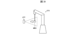
- the storage device 1B of Embodiment 3 for example, after the robot arm 273 (see FIGS. 27 and 28) causes the reading unit 277 (see FIG. 24) to read the drug identification information, A medicine box is placed on the first transport section 112 .
- the automatic refillable storage device 1B may be configured to include one third transport section 15 .
- the storage device 1 has only one third transport unit 15 (here, it is assumed to have the 3-1 transport unit 15A)
- the storage device 1 as indicated by reference numeral 5001 in FIG.
- a detection unit 121 may be provided.
- the position detection unit 121 detects a medicine box that is close to or in contact with the side surface 1141 of the shutter 114 .
- the position detection unit 121 may be, for example, a reflective sensor.
- the position detection section 121 is provided at a position of the second side wall section 117 adjacent to the side surface 1141 of the shutter 114 . Further, the position detection portion 121 is provided at substantially the same height as the first detection portion 113 on the second side wall portion 117 . Like the first detection section 113 , the position detection section 121 may be provided at a position where it can detect the medicine box that is close to or in contact with the side surface 1141 of the shutter 114 .
- the control unit 21 identifies the position of the medicine box in the depth direction of the storage device 1 in the first transport unit 112 based on the detection result of the position detection unit 121 .
- the control unit 21 specifies the position of the medicine box based on the time from when the position detection unit 121 emits light to when the light is reflected by the medicine box and when the reflected light is received. As a result, the control unit 21 can specify the position of the medicine box transported from the first transport unit 112 to the 3-1 transport unit 15A in the depth direction of the storage device 1 in the 3-1 transport unit 15A. .
- the grasping section 171 of the 2nd conveying section 17 takes out the medicine box from the 3-1 conveying section 15A.
- the operator places the medicine box on the first transport section 112 without much awareness of its position on the first transport section 112 . Therefore, there is a high possibility that the positions of the medicine boxes in the depth direction of the storage device 1 in the 3-1 conveying section 15A are different for each medicine box. Therefore, the transport control unit 211 needs to specify the position of the medicine box in order to allow the grasping part 171 to take out the medicine box.
- the grasping unit 171 can accurately grasp the medicine box placed on the 3-1 transport unit 15A even when the positions of the medicine boxes are different.
- the storage apparatus 1 includes a 3-1 transport section 15A and a 3-2 transport section 15B as the third transport section 15, and the drug placed on the 3-1 transport section 15A is The box is conveyed to the 3-2 conveying section 15B by the medicine moving section 151.
- the control unit 21 determines the amount of movement of the medicine moving unit 151 when carrying out this transportation. may be specified. In this case, the positions of the medicine boxes in the depth direction in the 3-2 conveying section 15B can be aligned on the second conveying section 17 side. Therefore, the gripping section 171 can accurately grip the medicine box placed on the 3-2 conveying section 15B.
- the control unit 21 determines which surface of the medicine box corresponds to the side surface 1141 of the shutter 114. It is possible to specify at which position the two are in proximity or contact. Therefore, the position detection portion 121 does not have to be provided on the second side wall portion 117 .
- the position detection section 121 functions as an auxiliary detection section for the first detection section 113 .
- the width detection unit 13 may have the function of the position detection unit 121 . Also in this case, the position detection portion 121 does not need to be provided on the second side wall portion 117 .
- the ejector plate 1511 can be reciprocated between the position on the 3-1 conveying section 15A and the 3-2 conveying section 15B and the position on the housing side where the timing belt 1512 is provided. good.
- the ejector plate 1511 may be provided rotatably around a rotating shaft extending in the movement direction ( ⁇ Y-axis direction) of the ejector plate 1511 and provided in the housing.
- the transport control unit 211 when moving the ejector plate 1511 from the 3-1 transport unit 15A to the 3-2 transport unit 15B, moves the ejector plate 1511 from the 3-1 transport unit 15A to the 3rd -2 Move while positioned on the conveying section 15B.
- the transport control unit 211 moves the ejector plate 1511 from the 3-2 transport unit 15B to the 3-1 transport unit 15A
- the transport control unit 211 moves the ejector plate 1511 in a retracted state toward the housing.
- the operation (returning operation) of moving the ejector plate 1511 from the 3-2nd conveying portion 15B to the 3-1st conveying portion 15A and the operation of conveying the medicine box by the 3-1st conveying portion 15A are performed in parallel. can run.
- FIG. 7 An example of operation for receiving a medicine box into the storage device 1 will be described with reference to FIGS. 7 to 10.
- FIG. 1 the medicine boxes are placed on the storage shelf 30 such that the longitudinal direction of the medicine boxes coincides with the depth direction ( ⁇ Y-axis direction) of the storage device 1 .
- the second transport unit 17 stores the medicine box placed on the third transport unit 15 in the storage rack 30 with the direction unchanged or rotated by 180 degrees. The orientation of the medicine box is not changed in the transportation of the third transportation unit 15 . Therefore, in order to store the medicine box in the storage shelf 30 as described above, the medicine receiving part 11 is adjusted so that the longitudinal direction of the medicine box is oriented in the ⁇ Y-axis direction.
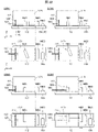
- FIG. 7 is a diagram showing an example of a process in which the medicine box MB1 placed on the first transport section 112 is transported to the 3-1 transport section 15A.
- FIG. 8 is a diagram showing an example of a process for adjusting the orientation of the medicine box MB1 received by the medicine receiving section 11. As shown in FIG.
- the operator puts the medicine box MB1 into the medicine receiving part 11 while holding it.
- the entrance/exit detection unit 115 transmits a detection signal indicating that the object (hand or arm of the operator) has been detected to the control unit 21 .
- the control unit 21 operates the reading unit 111 so that the medicine identification information can be read.
- the control unit 21 When the reading unit 111 reads the medicine identification information attached to the medicine box MB1 put into the medicine receiving unit 11, the control unit 21 outputs a sound for notifying that the medicine identification information has been read from the notification unit. to output Further, when the reading unit 111 reads the medicine identification information, the transport control unit 211 operates the first transport unit 112 to forward the first transport unit 112 as indicated by reference numeral 7001 in FIG. As a result, the medicine box MB1 is transported to the shutter 114, as indicated by reference numeral 7002 in FIG.
- the first detection unit 113 provided on the side surface 1141 of the shutter 114 detects the medicine box MB1.
- the transport control unit 211 receives a detection signal indicating that the medicine box MB1 has been detected from the first detection unit 113, the transport control unit 211 temporarily stops the transport of the medicine box MB1 by the first transport unit 112.
- the direction identification unit 213 determines whether or not the medicine box MB1 detected by the first detection unit 113 is oriented along the side surface 1141 of the shutter 114 ( ⁇ Y-axis direction). judge. In this embodiment, the direction specifying unit 213 determines whether or not the longitudinal direction of the medicine box MB1 is oriented in the ⁇ Y-axis direction.
- the first detection unit 113 also causes the detection signal to include information indicating which sensor 1131 has detected the medicine box. Furthermore, the control unit 21 can acquire information indicating the size of the medicine box by referring to the medicine database based on the medicine identification information read by the reading unit 111 . Therefore, the control unit 21 can specify the size of the medicine box in the direction along the side surface 1141 of the shutter 114 based on these pieces of information. That is, the direction specifying unit 213 can determine whether the longitudinal direction of the medicine box MB1 faces the direction along the side surface 1141 of the shutter 114 and is in proximity to or in contact with the shutter 114 based on these pieces of information.
- the direction specifying unit 213 determines that the longitudinal direction of the medicine box MB1 is oriented along the side surface 1141 of the shutter 114.
- the shutter control unit 212 determines whether or not a detection signal indicating that the object (hand or arm of the worker) has been detected has been received from the entrance/exit detection unit 115 .
- the shutter control unit 212 closes the shutter. 114 is opened. That is, the shutter control section 212 starts the operation of opening the shutter 114 when the operator's hand or arm is not inserted into the medicine receiving section 11 .
- the plurality of sensors 1131 of the first detection unit 113 provided on the shutter 114 are provided along one side of the side surface 1141 of the shutter 114 that can come into contact with the first conveying unit 112. . Moreover, the plurality of sensors 1131 emit light in a direction substantially perpendicular to the side surface 1141 of the shutter 114 . Therefore, when the shutter 114 moves vertically upward, the plurality of sensors 1131 cannot detect the medicine box when the upper end of the medicine box placed on the first transport section 112 is passed.
- the shutter control unit 212 may stop the operation of the shutter 114 after a predetermined distance or a predetermined period of time has elapsed since the plurality of sensors 1131 became unable to detect the medicine box. In this case, every time the shutter 114 is opened, it is not necessary to open the shutter 114 to the highest movable range of the shutter 114, and the shutter 114 can be opened according to the height of the medicine box.
- the shutter control unit 212 sets the position at which the operation of the shutter 114 is stopped, that is, the height of the medicine box detected by the first detection unit 113 with respect to the medicine box whose medicine identification information is read by the reading unit 111. It is determined whether or not the height is equal to or higher than the set value.
- the shutter control unit 212 can acquire the height of the medicine box received by the medicine receiving unit 11 by referring to the medicine database stored in the storage unit 23 based on the medicine identification information read by the reading unit 111.
- the height obtained by adding a predetermined value to the height of each medicine box registered in the medicine database is stored in advance as a setting value set for each medicine box.
- the control unit 21 may calculate the set value by adding the predetermined value when the height of the medicine box received by the medicine receiving unit 11 is acquired.
- a margin (for example, several millimeters) may be set so as not to allow conveyance to the 3-1 conveying section 15A.
- the transport control unit 211 restarts transport of the medicine box MB1 by the first transport unit 112. .
- the transport control unit 211 also forwards the third transport unit 15 .
- the medicine box MB1 can be placed on the 3-1 conveying section 15A so that the interval between the adjacent medicine boxes becomes a predetermined width. That is, the interval W2 between the medicine box MB2 already placed on the 3-1 transport section 15A and the medicine box MB3, and the distance between the medicine box MB2 and the medicine box MB1 transported to the 3-1 transport section 15A.
- the medicine boxes MB1 to MB3 can be placed on the 3-1 conveying section 15A with W1 being substantially the same.
- the transport control unit 211 forwards the first transport unit 112 .
- the first transport unit 112 transports the medicine box MB1 to the shutter 114 side.
- the transport control unit 211 temporarily stops the transport of the medicine box MB1 by the first transport unit 112.
- the first detection unit 113 cannot detect the medicine box MB1 over the entire length of the medicine box MB1 along the longitudinal direction of the medicine box MB1. Therefore, as indicated by reference numeral 8002, the transport control unit 211 restarts transport of the medicine box MB1 by the first transport unit 112 while the shutter 114 remains closed. As a result, since the first conveying unit 112 is sequentially fed while the medicine box MB1 is in contact with the side surface 1141 of the shutter 114, the longitudinal direction of the medicine box MB1 is aligned with the side surface 1141 of the shutter 114 as indicated by reference numeral 8003. can be directed to
- the direction specifying part 213 determines whether or not the longitudinal direction of the medicine box MB1 is along the side surface 1141 of the shutter 114 based on the detection result of the first detecting part 113. judge.
- the control unit 21 controls the shutter 114, the first transport section 112 and the third transport section 15 as described above. That is, as indicated by reference numerals 7002 and 7003, the medicine box MB1 on the first transport section 112 is transported onto the 3-1 transport section 15A after the shutter 114 is opened.
- the longitudinal direction of the medicine box is oriented along the side surface 1141 of the shutter 114 by the first conveying part 112 and the shutter 114 regardless of the orientation of the medicine box placed on the first conveying part 112. can be conveyed to the third conveying unit 15 in this state. Therefore, the medicine boxes received by the medicine receiving part 11 can be continuously placed on the third conveying part 15 in a state in which the directions of the medicine boxes are aligned. Therefore, the second conveying unit 17 can sequentially grip the medicine boxes with a simple mechanism.
- the drug boxes can be stored in the storage shelf 30 with the directions of the drug boxes aligned.
- the medicine box can be stored in the storage shelf 30 so that the longitudinal direction of the medicine box faces the depth direction of the storage device 1 .
- the longitudinal direction of the medicine box received by the medicine receiving part 11 can be oriented along the side surface 1141 of the shutter 114 . That is, the orientation of the medicine box received by the medicine receiving part 11 can be adjusted in the above-described direction by the simple configuration of the first conveying part 112 and the shutter 114 .
- the transport control section 211 can control the first transport section 112 and the third transport section 15 independently. Therefore, when the longitudinal direction of the medicine box is not in the direction along the side surface 1141 of the shutter 114, the transport control unit 211 keeps the shutter 114 closed while the first transport unit 112 is forwarded. The transport section 15 can be stopped. Then, the transport control unit 211 controls the first transport unit 112 and the third transport unit 15 in a state where the drug box is located at the position of the shutter 114 and the longitudinal direction of the drug box faces the direction along the side surface 1141 of the shutter 114 . to drive. As a result, a plurality of medicine boxes can be placed on the third conveying section 15 while maintaining a constant positional interval between the medicine boxes.
- the transport control unit 211 can independently control the first transport unit 112 and the third transport unit 15, the transport amount of the first transport unit 112 and the transport amount of the third transport unit 15 can be set respectively.
- the feed amount is the speed at which the conveying belt of the first conveying unit 112 or the conveying belt of the third conveying unit 15 is forwarded. Therefore, for example, the positional interval between the two medicine boxes can be arbitrarily set according to the feeding amount of the third conveying part 15 after conveying the medicine boxes from the first conveying part 112 to the third conveying part 15 .
- FIG. 9 is a diagram showing an operation example of the first transport section 112 and the shutter 114 when another medicine box MB2 is stacked on top of the medicine box MB1 placed on the first transport section 112.
- FIG. Reference numeral 9001 in FIG. 9 shows a state in which another medicine box MB2 is stacked on top of the medicine box MB1 placed on the first transport section 112 and transported to the shutter 114.
- the direction specifying unit 213 determines that the medicine box MB ⁇ b>1 is oriented along the side surface 1141 of the shutter 114 . Therefore, if a detection signal is received from the entrance/exit detection unit 115, the shutter control unit 212 opens the shutter 114 as indicated by reference numeral 9002 in FIG.
- the shutter control unit 212 when the height of the medicine box detected by the first detection part 113 is equal to or higher than the set value set for the medicine box whose medicine identification information is read by the reading part 111, the shutter control unit 212 , the shutter 114 is closed.
- shutter control unit 212 determines that the height of the medicine box detected by first detection unit 113 is equal to or greater than the set value set for medicine box MB1. , the shutter 114 is closed. In FIG. 9, the medicine box MB2 is placed on the medicine box MB1. Therefore, the shutter control unit 212 determines that the heights of the medicine boxes MB1 and MB2 detected by the first detection unit 113 are equal to or higher than the set value set for the medicine box MB1. The shutter 114 is closed as indicated by reference numeral 9003 . Then, as indicated by reference numeral 9004, the transport control unit 211 causes the first transport unit 112 to feed backward.
- the transport control unit 211 does not transport the medicine box placed on the first transport unit 112 to the third transport unit 15 . Therefore, in the third transport unit 15, the possibility that the medicine box is stacked on another medicine box can be reduced, and the medicine boxes can be placed one by one. Therefore, the second conveying unit 17 can grip the medicine boxes one by one.
- the shutter 114 when the shutter 114 is in an open state, it means that one medicine box whose medicine identification information has been read can pass through, and that a plurality of stacked medicine boxes are not allowed to pass through. indicates a state in which the shutter 114 is open. Further, the closed state of the shutter 114 indicates a state in which one medicine box whose medicine identification information is read cannot pass through.
- the shutter control unit 212 changes the shutter 114 to the closed state. may be maintained. Also, the transport control unit 211 does not have to reverse the first transport unit 112 . Also, the control unit 21 may use the touch panel 20, a lighting member (not shown), or the like to notify that the medicine box cannot be stored.
- FIG. 10 is a diagram showing an operation example of the first conveying section 112 when the longitudinal direction of the medicine box MB faces the forward feeding direction.
- the shutter 114 is opened when the longitudinal direction of the medicine box MB faces the direction along the side surface 1141 of the shutter 114 .
- the first detection unit 113 detects the medicine box MB over the entire length of the medicine box MB along the lateral direction of the medicine box MB.
- the shutter control unit 212 keeps the shutter 114 closed.
- the transport control unit 211 causes the first transport unit 112 to move backward.
- the control unit 21 may use the touch panel 20 or a lighting member (not shown) or the like to notify that the medicine box MB cannot be stored.
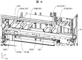
- FIG. 11 is a perspective view showing an example of the configuration of the second conveying section 17. As shown in FIG. In FIG. 11, illustration of the second storage 31B side is omitted.
- the second transport unit 17 is a device for gripping a drug box containing drugs and transporting the drug box to an arbitrary position.
- the second transport unit 17 stores the medicine box in the storage shelf 30 by transporting the medicine box from the third transport unit 15 to the storage position determined by the storage position management unit 214 .
- the second transport unit 17 transports the drug box containing the drug from the storage shelf 30 to the fifth transport unit 19. By doing so, the drug box is ejected to the outside.
- the second conveying section 17 includes a gripping section 171 and a conveying mechanism (lifter) 172 .
- Only one second transportation unit 17 may be provided in the storage device 1, or a plurality of the second transportation units 17 may be provided.
- two second transport units 17 are provided between the first storage 31A and the second storage 31B along the two first storage 31A and the second storage 31B provided in the storage device 1. may be
- the transport mechanism 172 is an action part for moving the grip part 171 to an arbitrary position within the storage device 1 .
- the transport mechanism 172 includes an X-axis rail portion 1721, a post 1722, an X-axis timing belt 1723, a Z-axis driving portion 1724, a Z-axis timing belt 1725, an X-axis driving portion 1726, an auxiliary timing belt 1727, and drive shaft 1728 .
- the X-axis rail portion 1721 is provided along the width direction ( ⁇ X-axis direction) of the storage device 1, and supports the strut 1722 so as to be slidable in the ⁇ X-axis direction. As shown in FIG. 11, the X-axis rail portion 1721 may be provided on both the top surface portion side and the floor surface portion side of the storage device 1 . That is, the column 1722 may be slidably supported in the ⁇ X-axis directions by the X-axis rail portions 1721 at both ends thereof.
- the strut 1722 is provided along the vertical direction ( ⁇ Z-axis direction) and supported by the X-axis rail portion 1721 .
- the strut 1722 is slidable in the ⁇ X-axis directions along the X-axis rail portion 1721 and supports the grip portion 171 .
- the strut 1722 is connected to an X-axis timing belt 1723 arranged along the X-axis rail portion 1721 .
- the X-axis timing belt 1723 on the top surface side of the storage device 1 is connected to one end of the drive shaft 1728 .
- the other end of drive shaft 1728 is connected to X-axis drive section 1726 via auxiliary timing belt 1727 .
- the X-axis timing belt 1723 on the floor side of the storage device 1 is also connected to the X-axis driving section 1726 .
- the X-axis timing belt 1723 can rotate according to the operation of the X-axis drive section 1726 controlled by the transport control section 211 . Therefore, the support 1722 can move along the X-axis rail portion 1721 .
- FIG. 12 is a perspective view showing an example of the configuration of the grip portion 171.
- the grasping unit 171 grasps the medicine box and moves it with the operation of the transport mechanism 172 to move the medicine box to an arbitrary position. Specifically, when the column 1722 moves along the X-axis rail portion 1721 , the gripping portion 171 moves along with the column 1722 in the width direction ( ⁇ X-axis direction) of the storage device 1 .
- the grip part 171 is movable in the vertical direction ( ⁇ Z-axis direction) along the support 1722 .
- the grip part 171 can move along the support 1722 by rotating the Z-axis timing belt 1725 provided on the support 1722 by the operation of the Z-axis driving part 1724 .
- the grasping portion 171 mainly includes a placement portion 1711 , an entrance/exiting portion 1712 and a temporary grasping portion 1713 .
- the placing section 1711 is a table for placing a medicine box.
- the mounting portion 1711 is a plate-shaped member that is larger than a medicine box that can be stored in the storage device 1, for example.
- a drug box pulled out from the storage shelf 30 and held between a pair of holding parts 1715 provided in the loading/unloading part 1712 is placed on the loading part 1711 .
- a plurality of medicine boxes may be placed on the mounting portion 1711 in a state of being aligned in the longitudinal direction of the mounting portion 1711 (extending direction of the pair of holding portions 1715; ⁇ X-axis directions in FIG. 12). In this case, the grip part 171 can simultaneously transport a plurality of medicine boxes.
- the loading/unloading part 1712 is for loading/unloading the medicine box with respect to the placement part 1711 .
- access section 1712 includes a pair of clamping section 1715 and pushing section 1716 .
- the pair of gripping units 1715 operate under the control of the transport control unit 211 to grip the medicine box by gripping the medicine box.
- the pair of holding portions 1715 are a pair of plate-like members extending along the longitudinal direction of the placing portion 1711 .
- the pair of holding portions 1715 operate symmetrically in the width direction of the placing portion 1711 ( ⁇ Y-axis directions in FIG. 12) under the control of the transport control portion 211 .
- the pair of plate-like members can also be referred to as gripping plates 1715a and 1715b, respectively.
- the gripping portion 171 has a pair of gripping portions 1715 on the side opposite to the side where the medicine box enters and exits the placing portion 1711 (the +X-axis direction side in FIG. 12). It has a Y-axis operation unit that operates along the width direction. That is, the grip portion 171 includes a Y-axis operation portion on the side opposite to the tip portion of the mounting portion 1711 (the inner side of the mounting portion 1711).
- the Y-axis motion unit includes, for example, a gear driving unit 1731, a gear 1732, and a pair of moving bodies 1733.
- the gear drive section 1731 rotates the gear 1732 and has a drive shaft along the longitudinal direction of the mounting section 1711 .
- a gear 1732 is connected to the drive shaft of the gear driving portion 1731 , and a pair of moving bodies 1733 extending along the width direction of the mounting portion 1711 are connected to the gear 1732 .
- the pair of moving bodies 1733 move in opposite directions. Gripping plates 1715 a and 1715 b are connected to each of the pair of moving bodies 1733 .
- the pair of holding portions 1715 can be opened and closed along the width direction of the mounting portion 1711 by the operation of the pair of moving bodies 1733 .
- the gripping plates 1715a and 1715b may be configured to move in the width direction of the placing portion 1711.
- the portion 171 can grip a medicine box.
- the Y-axis movement unit widens the gap between the gripping plates 1715a and 1715b so as to be wider than the width of the medicine box, and then widens the width of the medicine box. Narrow the gap until it is the same as
- the transport control unit 211 can specify the width of the medicine box by referring to the medicine database based on the medicine identification information read by the reading unit 111 . Note that the transport control section 211 may specify the width of the medicine box based on the detection result of the width detection section 13 .
- the pair of holding parts 1715 operates in the longitudinal direction of the placing part 1711 (the front-rear direction of the gripping part 171; the ⁇ X-axis direction in FIG. 12) under the control of the transport control part 211 .
- the gripping portion 171 includes an X-axis motion portion that moves a pair of holding portions 1715 along the longitudinal direction of the placing portion 1711 .
- the X-axis motion unit includes, for example, a clamping drive shaft 1741 and a clamping drive unit 1742 .
- the clamping drive shaft 1741 extends in the longitudinal direction of the placement section 1711 and is provided in the grip section 171 .
- a pair of clamping portions 1715 and a clamping support portion 1720 that supports the Y-axis operating portion are connected to the clamping drive shaft 1741 so as to be movable in the longitudinal direction of the mounting portion 1711 .
- the clamping drive section 1742 operates according to the control of the transport control section 211, the clamping drive shaft 1741 rotates about the center axis of the clamping drive shaft 1741 along the extension direction of the clamping drive shaft 1741 as a rotation axis.
- the pinching support portion 1720 can move in the longitudinal direction of the placing portion 1711 along with this rotation. That is, the pair of clamping portions 1715 can move in the longitudinal direction of the mounting portion 1711 due to the rotation of the clamping drive shaft 1741 .
- the grip part 171 When gripping a medicine box located outside the gripping part 171 (eg, a medicine box stored in the storage shelf 30), the grip part 171 operates as follows. That is, the gripping plates 1715a and 1715b in the fully opened state move from the mounting portion 1711 toward the direction of protruding outside the mounting portion 1711 (-X-axis direction in FIG. 12). After that, the width of the gripping plates 1715a and 1715b is narrowed so that the width is approximately the same as that of the medicine box positioned outside the gripping portion 171 . Thereby, the grasping part 171 can grasp the medicine box.
- the pair of gripping portions 1715 move from outside the placing portion 1711 in the direction returning to the placing portion 1711 (the +X-axis direction in FIG. 12), thereby moving out of the grip portion 171.
- a medicine box located can be retracted into the placement section 1711 .
- the pair of clamping portions 1715 are inclined inward from the connection side with the clamping support portion 1720 to the distal end portion (toward the ⁇ X-axis direction in FIG. 12). is doing. In other words, the distance between the gripping plates 1715a and 1715b is narrower on the tip end side than on the connection side with the holding support portion 1720. As shown in FIG. In other words, the pair of holding portions 1715 are inclined inward from the rear side to the front side of the mounting portion 1711 (from the rear side to the front side of the mounting portion 1711).
- the pair of clamping portions 1715 hold the drug box farthest from the grip portion 171.
- the plurality of drug boxes are pulled into the placement section 1711 .
- the gripping plates 1715a and 1715b are provided inclined as described above, the plurality of medicine boxes can be easily pulled into the placement section 1711. As shown in FIG.
- the push-out portion 1716 is a member for pushing out the medicine box from the grip portion 171.
- the pushing portion 1716 is a rod-shaped member that can move in the longitudinal direction of the placing portion 1711 ( ⁇ X-axis directions in FIG. 12).
- the pushing portion 1716 moves in the longitudinal direction of the mounting portion 1711 by the operation of an operation portion (not shown) under the control of the transport control portion 211 .
- the push-out portion 1716 moves from the mounting portion 1711 to the outside of the mounting portion 1711 ( ⁇ X-axis direction in FIG. 12).
- the medicine box can be moved out of the placing section 1711 .
- the pair of holding portions 1715 also function as guides when pushing out the medicine box to the target position.
- the loading/unloading section 1712 pulls the medicine box into the mounting section 1711 from the front of the mounting section 1711 (-X-axis direction in FIG. 12), and loads the medicine box placed on the mounting section 1711. It pushes out to the front of the placing portion 1711 .
- the push-out portion 1716 pushes out the medicine box placed on the placement portion 1711 to the outside of the placement portion 1711 .
- the medicine box placed on the mounting part 1711 is transported out of the mounting part 1711 by performing the operation opposite to that when the pair of holding parts 1715 pulls the medicine box into the mounting part 1711. You may
- the temporary gripping portion 1713 temporarily grips the medicine box placed on the front side of the placement portion 1711 (the -X-axis direction side in FIG. 12). As shown in FIG. 12 , the temporary grip portion 1713 is provided near the tip of the placement portion 1711 and includes a moving portion 1717 and a suction portion 1718 .
- the moving unit 1717 is an operating unit that is connected to the mounting unit 1711, supports the suction unit 1718, and is movable in the vertical direction ( ⁇ Z-axis direction in FIG. 12) under the control of the transport control unit 211. In other words, the moving part 1717 moves the adsorption part 1718 in the vertical direction with respect to the placing part 1711 .
- the suction section 1718 is for suctioning the medicine box placed on the front side of the placement section 1711 .
- the suction unit 1718 is a suction cup that can move in the vertical direction according to the operation of the moving unit 1717 controlled by the transport control unit 211 .
- the suction part 1718 may have a structure in which a plurality of suction cups, for example, three suction cups are arranged.
- the temporary grip part 1713 can stably grip the medicine box to some extent.
- the medicine box can be stably sucked without adjusting the positional relationship between the adjacent suction cups, unlike the case of two suction cups.
- the medicine box When the medicine box is positioned below the suction part 1718, the medicine box is sucked by moving the suction part 1718 vertically downward as the moving part 1717 operates. In addition, when the suction unit 1718 moves vertically upward while the medicine box is sucked, the medicine box is lifted and temporarily gripped. By temporarily gripping a medicine box in temporary grip part 1713 , grip part 171 can grip another medicine box in placing part 1711 .
- the gripping portion 171 grips the medicine box that exists on the near side as viewed from the gripping portion 171
- the temporary gripping portion 1713 temporarily grips the medicine box.
- the gripping portion 171 can grip the medicine box, which is located on the far side when viewed from the gripping portion 171 , on the mounting portion 1711 .
- the temporary gripping section 1713 is provided with the moving section 1717 and the suction section 1718, and can temporarily grip the medicine box placed on the front side of the placing section 1711 with a simple configuration.
- the transport control section 211 moves the adsorption section 1718 vertically downward in accordance with the operation of the moving section 1717 so that the adsorption section 1718 and the placement section 1711 are separated from each other.
- the drug box may be sandwiched between the two.
- the transport control section 211 may transport the grip section 171 to an arbitrary position. That is, the transport control unit 211 transports the grasping unit 171 from the third transport unit 15 to the storage shelf 30 or from the storage shelf 30 to the fifth transport unit 19 in the state where the medicine box is held in this manner. good too.
- transport control unit 211 may transport gripping unit 171 to an arbitrary position while temporarily gripping unit 1713 sucks a medicine box and placing another medicine box on placing unit 1711 .
- the grasping unit 171 includes a grasping detection unit 1714 and a passage detection unit 1751, as shown in FIG.
- the grip detection section 1714 is a sensor arranged outside the pair of holding sections 1715 in the width direction of the placement section 1711 ( ⁇ Y-axis direction in FIG. 12). Specifically, the grip detection unit 1714 is provided outside each of the grip plates 1715a and 1715b of the pinching support unit 1720. As shown in FIG. As an example, the gripping detection unit 1714 includes an emitting unit that emits light toward the front of the gripping unit 171 and a reflected light beam that is the emitted light reflected by the object, substantially parallel to the long sides of the pair of gripping units 1715 . It may be a reflective sensor having a light receiving portion that receives the light.
- the grip detection unit 1714 detects, for example, a medicine box that exists in front of the grip unit 171 .
- the grip detection unit 1714 transmits a detection signal indicating detection of the medicine box to the control unit 21, so that the transport control unit 211 can determine whether the pair of holding units 1715 can be moved.
- the grip detection unit 1714 does not detect the medicine cabinet.
- the transport control section 211 can grip the medicine box by moving the pair of holding sections 1715 forward of the placing section 1711 ( ⁇ X-axis direction in FIG. 12).
- the grip detection section 1714 detects the drug box.
- the pair of clamping portions 1715 moves forward of the mounting portion 1711, there is a possibility that the leading ends of the pair of clamping portions 1715 will collide with the medicine box. Therefore, when the grip detection unit 1714 detects the medicine box, the transport control unit 211 widens the gap between the pair of gripping units 1715 (that is, the gripping plates 1715a and 1715b) a little (eg, several millimeters).
- the transport control unit 211 repeats this operation until the grip detection unit 1714 no longer detects the medicine box.
- the transport control unit 211 moves the pair of clamping units 1715 to the front of the placement unit 1711 . Thereby, the pair of holding portions 1715 can grip the medicine box.
- the control portion 21 uses the touch panel 20 or a lighting member (not shown) to detect the medicine. It may be notified that the box cannot be grasped.
- the passage detection unit 1751 detects a medicine box pulled into the mounting part 1711 or a medicine box pushed out from the mounting part 1711 .
- the passage detection unit 1751 may be a reflective sensor that includes an emitting unit that emits light vertically upward and a light receiving unit that receives the reflected light of the emitted light reflected by an object.
- the passage detection section 1751 is provided below the mounting section 1711 on the front end side of the mounting section 1711 ( ⁇ X-axis direction side in FIG. 12).
- the passage detection unit 1751 transmits a detection signal indicating that the medicine box has been detected to the control unit 21 , whereby the control unit 21 can identify the passage state of the medicine box on the front end side of the placement unit 1711 .
- the control unit 21 specifies whether the grip unit 171 pulled in and gripped the medicine box, or whether the grip unit 171 pushed the medicine box out of the grip unit 171. can. In other words, the control unit 21 can identify the transfer of the medicine box between the gripping unit 171 and the outside of the gripping unit 171 based on the detection result of the passage detection unit 1751 . Further, the control unit 21 determines the width of the medicine box in the longitudinal direction ( ⁇ Y width along the axial direction) can be calculated. Thereby, the control unit 21 can specify whether or not the object to be transferred by the grasping unit 171 is the desired medicine box.
- the gripping portion 171 includes a rotation driving portion 1755 that rotates the gripping portion 171 around the vertical direction (specifically, around the rotation axis Ax1 of the rotation driving portion 1755).
- the rotation driving section 1755 is provided below the mounting section 1711 .
- the rotation drive unit 1755 operates under the control of the transport control unit 211 to move the leading end sides of the pair of clamping units 1715 to the third transport unit 15, the storage shelf 30 of the first storage 31A, and the second storage. 31B storage shelf 30 and the fifth transport section 19, respectively.
- the storage device 1 includes two second transport units 17 .
- the positions of the two gripping portions 171 are controlled so that the gripping portions 171 do not collide with each other when one second transporting portion 17 passes another second transporting portion 17 .
- the transport control unit 211 controls the rotation drive unit 1755 in the two second transport units 17 so that the longitudinal direction of the gripping unit 171 is oriented in the advancing direction (width direction of the storage device 1; ⁇ X-axis direction). Rotate the grip part 171 so that it faces.
- the transport control unit 211 controls the Z-axis driving unit 1724 to adjust the height of the two gripping portions 171 so that the two gripping portions 171 do not collide with each other.
- the transport control unit 211 controls the X-axis driving unit 1726 to move the two gripping portions 171 in the width direction of the storage device 1, thereby causing the two gripping portions 171 to pass each other.
- FIG. 13 shows an operation example when the second transport unit 17 pulls out and grips the medicine box MB1 on the third transport unit 15, and pushes out the gripped medicine box by the second transport unit 17 and stores it in the storage shelf 30.
- FIG. 10 is a diagram showing an operation example when
- figures with reference numeral A such as 13001A, show the gripping portion 171 viewed from the side (+Y-axis direction in FIG. 12).
- 13001B and other figures with reference numeral B show a state in which the grip portion 171 is viewed from the front ( ⁇ X axis direction in FIG. 12).
- the transport control unit 211 causes the second transport unit 17 to operate while the medicine box is placed on the third transport unit 15 . Specifically, as indicated by reference numeral 13001 in FIG. 13 , the transport control unit 211 moves the gripping part 171 so that the gripping part 171 is positioned facing the medicine box MB1 placed on the third transporting part 15 . to move.
- the transport control unit 211 moves the support 1722 along the X-axis rail portion 1721 to align the holding portion 171 and the medicine box MB1 in the width direction of the storage device 1 . Further, the transport control unit 211 moves the gripping part 171 along the support 1722 to align the gripping part 171 and the medicine box MB1 in the Z-axis direction.
- the transport control unit 211 sets the distance between the pair of holding parts 1715 (that is, the gripping plates 1715a and 1715b) to be wider than the width of the medicine box MB1 to be transported.
- a pair of clamping portions 1715 are opened so that Thereafter, as indicated by reference numeral 13003 in FIG. 13, the transport control section 211 moves the pair of holding sections 1715 toward the third transport section 15 side.
- the transport control part 211 narrows the gap between the gripping plates 1715a and 1715b, as indicated by reference numeral 13004 in FIG. Specifically, the transport control unit 211 operates the gripping plates 1715a and 1715b so that the gap between the gripping plates 1715a and 1715b is approximately the same as or slightly narrower than the width of the medicine box MB1.
- the width of the medicine box MB ⁇ b>1 may be specified based on the size of the medicine box MB ⁇ b>1 stored in the storage unit 23 or the width detected by the width detection unit 13 . As a result, the gripping portion 171 grips the medicine box MB1.
- the transport control section 211 moves the pair of holding sections 1715 to the placement section 1711 side.
- the medicine box MB ⁇ b>1 is pulled out from the third transport section 15 and placed on the placement section 1711 .
- transport control portion 211 After moving gripping portion 171 to a position facing another medicine box MB1, transport control portion 211 causes gripping portion 171 to grip a plurality of medicine boxes MB1 by repeatedly executing the above operation. good too.
- the transport control unit 211 causes the second transport unit 17 to grip the medicine box MB1 and then dispense it at the target position. Specifically, the transport control unit 211 moves the gripping unit 171 gripping the medicine box MB1 to the storage position where the medicine box MB1 is stored in the storage shelf 30 .
- the storage location is a location specified by the storage location management unit 214, for example.
- the method of moving the gripping portion 171 to the storage position is the same as the method of moving the gripping portion 171 to the position facing the medicine box MB1.
- the transport control part 211 After moving the gripping part 171 to the storage position, the transport control part 211 widens the pair of holding parts 1715 slightly. After that, the transport control unit 211 moves the grasping unit 171 toward the storage shelf 30, and then causes the pushing unit 1716 to protrude. As a result, the medicine box MB1 placed on the placing portion 1711 is moved to the storage shelf 30.
- the transport control unit 211 may cause the pushing part 1716 to protrude while moving the pair of holding parts 1715 toward the storage shelf 30 side.
- the drug box MB1 is positioned so that the tips of the pair of holding parts 1715 are located on the moving direction side of the pair of holding parts 1715 or the pushing part 1716 from the center of gravity of the drug box MB1 pushed by the pushing part 1716. I wish I could move.
- the pair of clamping parts 1715 can function as guides for guiding the medicine box MB1 to the target position.
- the transport control unit 211 moves the pair of clamping units 1715 toward the placing unit 1711 as indicated by reference numeral 13006 in FIG. is moved to the placement section 1711 side.
- the push-out portion 1716 can fix the position of the medicine box MB1 placed on the storage shelf 30 while the pair of holding portions 1715 is moved toward the placing portion 1711 side. Therefore, it is possible to reduce the possibility of displacement of the medicine box MB1 due to the pair of holding parts 1715 coming into contact with the medicine box MB1 during movement.
- the transport control unit 211 causes the pair of holding parts 1715 to hold the drug box placed on the placing part 1711, and then the pair of holding parts 1715 holding the drug box. 1715 may be moved to the storage shelf 30 . Further, the transport control unit 211 may perform opening/closing control of the pair of clamping units 1715 after the medicine box is stored in the storage shelf 30 . Specifically, the transport control unit 211 may open the pair of clamping units 1715 storing the medicine box in the storage shelf 30, then close them once, and then open them again. Here, in the closing operation, it is preferable to operate the gripping plates 1715a and 1715b such that the gap between the pair of holding portions 1715 is slightly narrower than the width of the medicine box MB1.
- the direction of the medicine box stored in the storage shelf 30 can be adjusted to be in the ⁇ Y-axis direction.
- the speed of the opening/closing operation executed to adjust the orientation of the medicine box may be slower than the speed of the initial opening operation. In this case, it is possible to prevent or reduce the orientation deviation of the medicine box (deviation in the ⁇ Y-axis direction) that accompanies the storage operation on the storage shelf 30 .
- the same operations as those described with reference to the reference numerals 13001 to 13005 may be performed. Further, when dispensing the medicine box MB1 taken out from the storage shelf 30 to the fifth transport section 19, the same operation as the operation described with reference to the reference numeral 13006 may be performed.
- FIG. 14A and 14B are diagrams showing an operation example of the second transport section 17 when only the medicine box MB2 located on the back side of the storage shelf 30 is taken out as a transport target.
- first-in, first-out means that when a plurality of drug boxes of the same type are arranged in the depth direction of the storage device 1 and stored in the storage shelf 30, the drug boxes whose expiration date is close (the order in which the expiration date comes) This means that a medicine box with a later expiration date (medicine box with a later expiration date) is to be dispensed earlier than a medicine box with a later expiration date.
- the expiry date has been described as the standard, the date obtained by adding a predetermined period to the manufacturing date of the drug may be used as the standard.
- the drug box with a farther manufacturing date a drug box with a longer period of time since the manufacturing date
- the drug box with a closer manufacturing date a drug box with a shorter period of time after the manufacturing date. It means that it will be paid out first.
- a drug box MB1 with a long expiration date that is not to be taken out (not to be transported) is stored on the front side of the storage shelf 30, and an effective drug box MB1 that is to be taken out (dispensed) is stored on the back side of the storage shelf 30.
- a case where a medicine box MB2 whose expiration date is near is stored is taken as an example.
- the transport control part 211 moves the grip part 171 to the storage position where the medicine box MB2 is stored in the storage shelf 30. Subsequently, as indicated by reference numeral 14001 in FIG. 14, the transport control section 211 operates the pair of holding sections 1715 to hold the medicine box MB1 stored in the storage shelf 30 by the pair of holding sections 1715. . Subsequently, as indicated by reference numeral 14002 in FIG. 14, the transport control unit 211 moves the pair of clamping units 1715 toward the placement unit 1711, thereby pulling out the medicine box MB1 from the storage shelf 30 and placing it on the placement unit. 1711. The method of gripping and pulling out the medicine box MB1 using the pair of holding portions 1715 is the same as the method described with reference to FIG.
- the transport control unit 211 operates the temporary gripping unit 1713 to temporarily grip the medicine box MB1. Specifically, as indicated by reference numeral 14003 in FIG. 14, the transport control unit 211 operates the moving unit 1717 (see FIG. 12) to move the adsorption unit 1718 vertically downward (in the direction in which the medicine box MB1 exists). ) to cause the adsorption portion 1718 to adsorb the medicine box MB1. Subsequently, as indicated by reference numeral 14004 in FIG. 14, the transport control section 211 operates the moving section 1717 to move the suction section 1718 vertically upward. At this time, as indicated by reference numerals 14003B and 14004B in FIG. 14, the transport control unit 211 widens the gap between the pair of holding portions 1715 to make the medicine box MB1 movable. As a result, the medicine box MB ⁇ b>1 is temporarily gripped by the temporary gripping portion 1713 .
- the transport control unit 211 pulls out the medicine box MB2 to be transported from the storage shelf 30 while the temporary gripping part 1713 is gripping the medicine box MB1. Since the method of pulling out the medicine box MB2 from the storage shelf 30 is the same as the method described using reference numerals 14001 and 14002, the description is omitted. 14, the medicine box MB2 is pulled out so as to be positioned on the far side of the mounting section 1711 relative to the medicine box MB1.
- the transport control section 211 widens the gap between the pair of holding sections 1715 and moves the suction section 1718 vertically downward.
- the transport control part 211 causes the temporary grip part 1713 to release the temporary grip of the medicine box MB1. That is, the transport control unit 211 cancels the adsorption of the medicine box MB1 by the adsorption unit 1718 .
- the transport control unit 211 moves the medicine box MB1 to the storage shelf 30 side by projecting the pushing part 1716 after or while moving the pair of holding parts 1715 to the storage shelf 30 side.
- the transport control part 211 moves the pair of clamping parts 1715 as indicated by reference numeral 17008 in FIG. It is returned to the placement section 1711 side.
- the transport control section 211 returns the pushing section 1716 to the placing section 1711 side.
- the transport control unit 211 causes the pair of gripping units 1715 to operate again, causing the pair of gripping units 1715 to grip the medicine box MB2 located on the gripping unit 171 side, It is placed on the placing portion 1711 .
- the transport control unit 211 operates each part of the second transport unit 17, so that another medicine box MB1 not to be transported is placed in front of the medicine box MB2 to be transported when viewed from the grip unit 171. Even if it is positioned, only the medicine box MB2 can be made to be gripped by the gripping portion 171 .
- the loading/unloading part 1712 may change the order of the two medicine boxes and hold them. Specifically, the temporary gripping portion 1713 temporarily grips the medicine box (first medicine box) first pulled into the placing portion 1711 by the loading/unloading portion 1712 .
- the loading/unloading portion 1712 is located on the rear side (+X-axis in FIG. direction side), another medicine box (second medicine box) to be drawn next to the medicine box may be drawn.
- the medicine box drawn first is positioned on the rear side of the mounting section 1711, and another medicine box drawn next is positioned on the front side of the mounting section 1711.
- the medicine box drawn first can be placed on the front side of the placing section 1711, and the medicine box drawn next can be placed on the rear side of the placing section 1711, respectively. Therefore, the second transport section 17 can reverse the arrangement order of the two medicine boxes on the placement section 1711 from that in the normal retraction operation.
- the temporary gripping part 1713 places the temporarily gripped drug box (first drug box). It may be placed on the portion 1711 .
- the loading/unloading unit 1712 pushes the medicine box placed on the mounting part 1711 from the rear side of the mounting part 1711 to push out the temporarily gripped medicine box to the front of the mounting part 1711 .
- the second conveying unit 17 returns the medicine box positioned on the near side as seen from the gripping part 171 to the storage shelf 30 that is the location from which it was taken in, and returns it to the back side as seen from the gripping part 171 . Only drug boxes that were located in
- FIG. 15A and 15B are diagrams showing another example of the operation of the second conveying section 17 when taking out only the medicine box MB2 located on the far side of the storage shelf 30.
- FIG. 15A and 15B are diagrams showing another example of the operation of the second conveying section 17 when taking out only the medicine box MB2 located on the far side of the storage shelf 30.
- the transport control unit 211 moves the pair of clamping units 1715 forward to narrow the gap between the pair of clamping units 1715, thereby increasing the storage shelf 30.
- a pair of gripping portions 1715 are caused to grip the medicine box MB2 on the back side of the .
- the transport control unit 211 moves the pair of clamping portions 1715 to the rear of the placing portion 1711 while holding the medicine box MB2 between the pair of clamping portions 1715. move towards.
- the medicine box MB2 is pulled into the mounting portion 1711.
- the medicine box MB1 existing on the front side of the storage shelf 30 is also pulled into the placing section 1711 together with the medicine box MB2.
- transport control unit 211 After the medicine box MB2 is pulled in, the transport control unit 211 lowers the suction unit 1718 to suck the medicine box MB2, as indicated by reference numeral 15003 in FIG. Subsequently, as indicated by reference numeral 15004 in FIG. 15, transport control unit 211 raises adsorption unit 1718 and causes temporary gripping unit 1713 to temporarily grip medicine box MB2.
- the transport control section 211 moves the pushing section 1716 forward while widening the gap between the pair of holding sections 1715 .
- the transport control unit 211 moves the pushing unit 1716 to the rear of the placing unit 1711, as indicated by reference numeral 15006 in FIG.
- the transport control section 211 lowers the suction section 1718 to release the temporary grip of the medicine box MB2. Finally, as indicated by reference numeral 15008 in FIG. 15, the transport control unit 211 raises the suction unit 1718 that has released the suction of the medicine box MB2.
- the temporary holding portion 1713 temporarily You can grab it. After that, the loading/unloading section 1712 may push the medicine box placed on the rear side of the placing section 1711 forward of the placing section 1711 .
- the medicine box placed on the front side of the placing section 1711 (the medicine box pulled into the placing section later) is placed on the rear side of the placing section 1711.
- the medicine box (the medicine box first pulled into the mounting part) is pushed forward of the mounting part 1711 .
- the drug box placed on the front side of the placement section 1711 (the drug box pulled into the placement section later) is temporarily held by the temporary holding section 1713.
- the medicine box placed on the rear side of the placing portion 1711 (the medicine box first pulled into the placing portion 1711) can be pushed forward onto the placing portion 1711 first. Therefore, the second conveying unit 17 returns the drug box that was first pulled into the placement unit 1711 to the storage rack 30, which is the location from which it was taken in, and only the drug boxes that were subsequently pulled into the placement unit 1711 are returned. can be transported.
- the transport control unit 211 can cause the gripping unit 171 to simultaneously grip a plurality of medicine boxes by executing the operations indicated by reference numerals 15001 and 15002 in FIG. Further, for example, the transport control unit 211 can move the plurality of medicine boxes out of the placement unit 1711 at the same time by pushing out the plurality of medicine boxes gripped by the gripping part 171 with the pushing part 1716 .
- FIG. 16 is a perspective view showing an example of the configuration of the fifth conveying section 19. As shown in FIG. In FIG. 16, only the portion of the fifth transport section 19 provided inside the storage device 1 is illustrated.
- the fifth conveying unit 19 is a conveying unit for dispensing medicine boxes from the storage device 1 to the outside. In this embodiment, the fifth transport unit 19 dispenses medicine boxes from the storage device 1 to an external device (eg drug station 2). As shown in FIG. 16 , the fifth transport section 19 includes a receiving transport section 191 and a discharge transport section 192 .
- the receiving transport unit 191 is a transport unit that receives the medicine box that has been taken out of the storage shelf 30 by the second transport unit 17 and transported, and transports it toward the discharge transport unit 192 .
- the receiving/conveying section 191 is a belt conveyor capable of conveying medicine boxes placed on the receiving/conveying section 191 from the second conveying section 17 side toward the discharge conveying section 192 side, in other words, in the -Y-axis direction. is.
- a plurality of receiving and transporting units 191 are provided as the receiving and transporting units 191 .
- a first receiving/conveying section 191A, a second receiving/conveying section 191B, a third receiving/conveying section 191C, and a fourth receiving/conveying section 191D are provided as the receiving/conveying section 191 .
- Two belt conveyors are arranged adjacent to each other in the first receiving/conveying section 191A.
- the second receiving/conveying section 191B, the third receiving/conveying section 191C, and the fourth receiving/conveying section 191D are configured by one belt conveyor.
- the number of receiving and transporting units 191 may be determined depending on the scale of the storage apparatus 1, etc., and may be one. Also, the number of belt conveyors in the first receiving/conveying sections 191A to 191D may be determined by an experiment or the like for confirming the conveyance of medicine boxes to the discharging/conveying section 192. FIG.
- the discharging conveying section 192 is, for example, a belt conveyor located downstream of the receiving conveying section 191 in the forward feeding direction.
- the forward direction of the receiving/conveying section 191 means that the conveying belt of the receiving/conveying section 191 is operated so as to convey the placed medicine box toward the discharging/conveying section 192 (-Y axis direction).
- the forward direction of the discharge/conveyance unit 192 means that the conveyance belt of the discharge/conveyance unit 192 is operated so as to convey the placed medicine box to the outside of the storage device 1 (+X-axis direction).
- the discharge transport section 192 further transports the medicine box transported from the receiving transport section 191 and discharges it to the outside of the storage device 1 .
- the output transport 192 extends from the storage device 1 to a picking unit 202 located distally from the storage device 1, located outside the storage device 1.
- an input box 40 into which medicine boxes transported from the discharge transport part 192 are put is provided below the discharge transport part 192 at a position corresponding to the picking unit 202 of the discharge transport part 192 . .
- the medicine box transported by the discharge transport section 192 drops into the input box 40 . Thereby, the operator can retrieve the medicine box from the input box 40 .
- the discharge transport section 192 is provided with a guide section 1921 that guides the medicine box transported from the first reception transport section 191A in the +X-axis direction.
- the guide portion 1921 constitutes the outer wall of the fifth transport portion 19 together with the outer wall 1911 of the first receiving transport portion 191A and the outer wall 1922 of the discharge transport portion 192 .
- the guide portion 1921 connects the outer wall 1911 extending in the ⁇ Y-axis direction and the outer wall 1922 extending in the ⁇ X-axis direction.
- the guide portion 1921 has a curved shape when the fifth conveying portion is viewed from above. As a result, the medicine box conveyed from the first receiving and conveying section 191A can be smoothly conveyed to the discharging and conveying section 192 .
- the first receiving belt conveyor 191Aa has a higher forward feeding speed than the second receiving belt conveyor 191Ab.
- the first receiving belt conveyor 191Aa is a belt conveyor positioned on the outer circumference of the medicine box in the conveying direction
- the second receiving belt conveyor 191Ab is a belt conveyor positioned on the inner circumference of the medicine box in the conveying direction.
- the outer periphery in the transport direction indicates the position outside the central axis when the medicine box turns along the guide portion 1921 when transported from the receiving transport portion 191 to the discharge transport portion 192, and is within the transport direction. Circumference indicates a position inside the central axis.
- the medicine boxes can be smoothly conveyed from the first receiving/conveying section 191A to the discharging/conveying section 192. can.
- the diameter of the pulley that rotates the conveyor belt of the first receiving belt conveyor 191Aa is made larger than the diameter of the pulley that rotates the conveyor belt of the second receiving belt conveyor 191Ab.
- FIG. 17 is a diagram showing an arrangement example of the receiving transport section 191 with respect to the discharging transport section 192.
- the receiving transporter 191 may be arranged substantially perpendicular to the discharging transporter 192 when the fifth transporter 19 is viewed from above.
- the receiving transport section 191 is arranged so that the forward feeding direction of the receiving transport section 191 is inclined with respect to the discharge transport section 192. may be arranged with respect to the discharge transport section 192 .
- one end of the receiving and conveying portion 191 on the side contacting the discharging and conveying portion 192 is positioned downstream of the other end of the receiving and conveying portion 191 in the forward feeding direction of the discharging and conveying portion 192 ( ⁇ X axis direction). ).
- the transport surfaces of the reception transport section 191 and the discharge transport section 192 on which the medicine boxes are transported are substantially horizontal.
- the conveying surface of the receiving conveying portion 191 and the conveying surface of the discharge conveying portion 192 may form an obtuse angle in the cross section.
- the fifth conveying section 19 includes an opening/closing section 193 .
- FIG. 18 is a perspective view showing an example of the configuration of the opening/closing portion 193. As shown in FIG.
- the opening/closing part 193 is a belt conveyor provided above the input box 40 on the downstream side of the discharging/conveying part 192 in the forward feeding direction.
- the opening/closing unit 193 can convey the medicine box in the same direction as the discharging/conveying unit 192 by rotating the conveying belt in the same direction as the discharging/conveying unit 192 under the control of the conveying control unit 211 .
- the opening/closing portion 193 is rotatable about the side located at the downstream end of the opening/closing portion 193 in the forward feed direction as the rotation axis Ax2.
- the opening/closing portion 193 can be opened/closed around the sides.
- the input box 40 is provided corresponding to each picking unit 202 .
- an opening/closing part 193 is provided above the input box 40 provided corresponding to the picking unit 202 provided proximally from the storage device 1 .
- an open/close A section 193 is provided above the input boxes 40 other than the input box 40 provided farthest from the storage device 1 (the input box 40 provided in the middle of the discharge transport section 192).
- the transport control unit 211 controls the opening/closing unit located above the throw-in box 40. 193 is opened.
- the transport control unit 211 operates the opening/closing unit 193 positioned above the input box 40 provided corresponding to at least one picking unit 202 provided closer to the storage device 1 than the picking unit 202 concerned. , remain closed.
- the transport control section 211 opens the input box 40 into which the medicine box is to be input.
- the drug box can be thrown into the throw-in box 40 provided corresponding to the picking unit 202 provided distally from the storage device 1 .
- the transport control unit 211 opens only the opening/closing part 193 located above the input box 40 to which the medicine box is to be transported, and keeps the other opening/closing parts 193 closed. A drug box can be thrown into the previous throw-in box 40. - ⁇
- the fifth transport section 19 may include a slide section 194 instead of the opening/closing section 193 .
- FIG. 19 is a perspective view showing an example of the configuration of the slide portion 194. As shown in FIG. Reference numeral 19001 in FIG. 19 indicates a state in which the slide portion 194 is not extended, and reference numeral 19002 indicates a state in which the slide portion 194 is extended. 20 is a side sectional view of the slide portion 194. As shown in FIG. Reference numeral 20001 in FIG. 20 indicates a state in which the slide portion 194 is not extended, and reference numeral 20002 indicates a state in which the slide portion 194 is extended.
- the discharge transport section 192 includes a slide section 194 .
- the slide section 194 is a belt conveyor connected to a belt conveyor (also referred to as an internal belt conveyor) forming part of the discharge transfer section 192 inside the storage device 1 .
- the slide portion 194 is provided at least partially above the throw-in box 40 and expands and contracts under the control of the control portion 21 .
- the slide portion 194 includes a slide base portion 1941 and a slide movable portion 1942 .
- the slide base portion 1941 and the slide movable portion 1942 suspend the transport belt 1943 so that the medicine box can be transported in the same direction as the internal belt conveyor.
- the slide base 1941 is connected to an internal belt conveyor and has a first base rotation axis 1944 and a second base rotation axis 1945 .
- the first base rotating shaft 1944 suspends the transport belt 1943 at the upstream end of the slide portion 194 in the forward feeding direction, and rotates the transport belt 1943 in the forward feeding direction (clockwise in FIG. 20).
- the position of the first base rotation shaft 1944 defines the position of the upstream end in the forward feeding direction of the surface (conveyance surface) of the conveyor belt 1943 that contacts the medicine box.
- the second base rotation shaft 1945 suspends the conveyor belt 1943 downstream of the first base rotation shaft 1944 in the forward feeding direction, and rotates in the same direction as the first base rotation shaft 1944 .
- the second base rotation shaft 1945 is arranged below the first base rotation shaft 1944 .
- the slide movable part 1942 is provided slidably in the ⁇ X-axis directions with respect to the slide base part 1941 and includes a first movable part rotation shaft 1946 and a second movable part rotation shaft 1947 .
- the first movable part rotating shaft 1946 suspends the conveying belt 1943 at the forward feeding direction downstream end of the slide part 194 and rotates in the same direction as the first base rotating shaft 1944 and the second base rotating shaft 1945 .
- the position of the first movable part rotating shaft 1946 defines the position of the forward feeding direction downstream end of the surface of the conveyor belt 1943 that contacts the medicine box.
- the second movable part rotating shaft 1947 suspends the conveying belt 1943 upstream of the first movable part rotating shaft 1946 in the forward feeding direction, and rotates in the same direction as the first movable part rotating shaft 1946 . Further, as shown in FIG. 20 , the second movable portion rotating shaft 1947 is arranged below the first movable portion rotating shaft 1946 .
- the conveyor belt 1943 is shortened when the slide base portion 1941 and the slide movable portion 1942 are close to each other. In this state, the top surface of the throw-in box 40 is open. Therefore, in this state, by rotating the rotating shaft (the rotating shaft indicated by reference numerals 1944 to 1947), the medicine box conveyed from the internal belt conveyor and delivered on the conveying belt 1943 is put into the input box 40. be.
- the slide base portion 1941 and the slide movable portion 1942 move in the +X-axis direction from the state in which the slide base portion 1941 and the slide movable portion 1942 are close to each other. It extends in the +X-axis direction.
- the upper surface of the input box 40 is blocked by the conveyor belt 1943 . Therefore, in this state, the rotation of the rotating shaft (the rotating shaft indicated by reference numerals 1944 to 1947) causes the medicine box conveyed from the internal belt conveyor and transferred onto the conveying belt 1943 to move downstream from the slide portion 194. transported to
- the movement of the transport belt 1943 in the ⁇ X-axis direction allows the drug boxes to be transported.
- the drug box can be put into the box 40 .
- the movement timing of the conveyor belt 1943 may be the same as the opening/closing timing of the opening/closing portion 193 .
- the fifth transport section 19 may have a configuration in which neither the opening/closing section 193 nor the slide section 194 is provided.
- the delivery box 40 may be provided at the distal end of the discharge/conveyor 192 from the storage device 1 , and the medicine box dropped from the end may be placed into the delivery box 40 .
- FIG. 21 is a diagram showing a throw-in box 40A that is a modification of the throw-in box 40.
- Reference numeral 21001 in FIG. 21 is a cross-sectional view of the input box 40 taken along a horizontal plane.
- Reference numeral 21002 in FIG. 21 is a cross-sectional view of the throw-in box 40A taken along a horizontal plane.
- Reference numerals 21001 and 21002 are cross-sectional views of the input boxes 40 and 40A, respectively, when viewed from above.
- Reference numeral 21003 in FIG. 21 is a cross-sectional view of the throw-in box 40A taken along line X1-X2.
- the input box 40 has a substantially rectangular parallelepiped hollow portion.
- the hollow portion is defined by a first input side wall portion 402, a second input side wall portion 403, a third input side wall portion 404, an input bottom portion 405, and an opening/closing portion 193 (not shown in FIG. 21), as indicated by reference numeral 21001.
- the input opening 401 is defined by the first input side wall 402 , the third input side wall 404 , the input bottom 405 , and the opening/closing portion 193 .
- the second input side wall portion 403 is a side wall portion facing the input opening portion 401 .
- the first input side wall portion 402 and the third input side wall portion 404 are side wall portions extending from both ends of the second input side wall portion 403 .
- the opening/closing portion 193 constituting the top surface portion of the input box 40 is in the open state, the drug boxes input from the ejection transport portion 192 are placed on the input bottom portion 405 . This allows the operator to take out the medicine box from the loading opening 401 .
- the top surface of the throw-in box 40 may be defined by a slide portion 194 instead of the opening/closing portion 193 .
- the input box 40A replaces the first input side wall portion 402, the third input side wall portion 404, and the input bottom portion 405 with the first input side wall portion 402a and the third input side wall portion 402a, respectively. It comprises a portion 404a and an input bottom portion 405a.
- the inner walls of the first throw-in side wall portion 402a and the third throw-in side wall portion 404a are wider than the width of the throw-in opening portion 401 when the throw-in box 40A is viewed from the throw-in opening portion 401 side. It is inclined so that the width of the input side wall part 403 becomes large.
- the “width” here refers to the length in the ⁇ X-axis direction. That is, the hollow portion of the input box 40A is wider on the side of the second input side wall 403 than on the side of the input opening 401 in a cross section of the input box 40A taken along a horizontal plane.
- the medicine box in the injection box 40, as indicated by an arrow 21001, there is a possibility that the medicine box bounces toward the injection opening 401 at the third injection side wall 404 and jumps out of the injection opening 401.
- the inner wall of the third throw-in side wall portion 404a is inclined as described above.
- the medicine box can be bounced back toward the second injection side wall portion 403 at the third injection side wall portion 404a. Therefore, it is possible to reduce the possibility that the medicine box jumps out of the loading opening 401 at the third loading side wall portion 404a.
- the third input side wall portion 404 it is also possible to reduce the possibility that the bounced medicine box will jump out of the loading opening 401 .
- the size of the input box 40 increases. According to the injection box 40A, it is possible to reduce the possibility of the medicine box jumping out of the injection opening 401 without changing the size of the injection box 40.
- the inclination angle ⁇ 1 of the inner walls of the first loading side wall portion 402a and the third loading side wall portion 404a in the horizontal plane is determined by experiments and the like to facilitate the operator to take out the medicine box (the operator does not feel uncomfortable when taking out the medicine box). ) should be taken into account.
- the inner wall of the input bottom portion 405a is located above the height of the input opening 401 when the input box 40A is viewed from the input opening 401 side. It is slanted so that the height of 403 increases. That is, the hollow portion of the input box 40A is wider on the side of the second input side wall 403 than on the side of the input opening 401 in the cross section of the input box 40A taken along the vertical plane.
- the “vertical plane” here refers to a vertical plane perpendicular to the ⁇ X-axis directions.
- the input bottom portion 405a is slanted as described above, the possibility that the medicine box loaded from the discharging/conveying portion 192 and placed on the input bottom portion 405a moves toward the second input side wall portion 403 increases. be able to. Therefore, it is possible to reduce the possibility that the medicine box will pop out from the loading opening 401 .
- the inclination angle ⁇ 2 of the inner wall of the loading bottom portion 405a with respect to the vertical plane is set through experiments, etc., in consideration of the ease with which the operator can take out the medicine box (the operator does not feel uncomfortable when taking out the medicine box). All you have to do is
- the inner wall of the first input side wall portion 402a is inclined.
- the medicine container that has collided with the first loading side wall portion 402a after colliding with the third loading side wall portion 404a can bounce back toward the second loading side wall portion 403 side.
- the inner wall of the first loading side wall portion 402a does not have to be slanted, considering that the possibility of the medicine box colliding with the first loading side wall portion 402a is lower than that of the third loading side wall portion 404a.
- the inner walls of the first input side wall portion 402a and the third input side wall portion 404a and the inner wall of the input bottom portion 405a are respectively inclined.
- at least one of the inner wall of the third throw-in side wall portion 404a and the inner wall of the throw-in bottom portion 405a may be inclined. Even in this case, it is possible to bounce the medicine box toward the second loading side wall portion 403 side.
- the protruding detection unit 25 detects a medicine box that protrudes from the storage shelf 30 toward the side where the second conveying unit 17 is provided.
- a plurality of storages in this embodiment, the first storage 31A and the second storage 31B
- a plurality of pop-out detectors 25 are provided to correspond to each of the plurality of storages. may be Although FIG. 11 shows only the pop-out detection unit 25 provided on the first storage 31A side, the pop-out detection unit 25 is also provided on the second storage 31B side.
- the pop-out detector 25 provided on the side of the first storage 31A will be described as an example.
- the projection detector 25 is slidably supported along the projection rail portion 251 .
- the protruding rail portion 251 is provided near the top surface portion of the storage device 1 along the width direction ( ⁇ X-axis direction) of the storage device 1 .
- the protrusion detector 25 can move from one end of the first storage 31A to the other by moving along the protrusion rail 251 .
- the protruding rail portion 251 is positioned on the boundary between the first storage 31A and the region in which the second transfer portion 17 is provided. Located near the top.
- the protrusion detection unit 25 is a sensor capable of detecting an object, and is provided so that the area capable of detecting the object faces vertically downward.
- the protrusion detection unit 25 may be a reflective sensor having an emission unit that emits light and a light reception unit that receives the reflected light of the emitted light reflected by the object. Under the control of the control unit 21 , the pop-out detection unit 25 moves from one end of the first storage 31A to the other end, and outputs the detection result to the control unit 21 .
- the control section 21 moves the ejection detection section 25 along the ejection rail section 251 and determines whether or not there is a medicine box that has been ejected from the storage shelf 30 .
- the controller 21 determines that there is a medicine box protruding from the storage shelf 30 based on the detection result of the protrusion detection part 25, the controller 21 uses the touch panel 20 or a lighting member (not shown) or the like to detect the medicine box. You may notify that it has jumped out of the storage shelf 30. - ⁇ As a result, the operator can return the medicine box jumped out of the storage shelf 30 to the storage shelf 30. - ⁇
- the pop-out detection unit 25 detects a medicine box that has jumped out of the storage shelf 30, thereby reducing the possibility that the second conveying unit 17 will operate and come into contact with the medicine box.
- the medicine box may be stored in the storage shelf 30 such that the lateral direction of the medicine box faces the depth direction of the storage device 1 .
- the longitudinal direction of the medicine box should be read as the transverse direction of the medicine box, and the transverse direction of the medicine box should be read as the longitudinal direction of the medicine box. Unless otherwise specified, other embodiments can be read similarly.
- the medicine box is conveyed to the third conveying section 15. be. That is, regardless of whether the medicine box is placed vertically or horizontally, the medicine box is conveyed to the third conveying unit 15 as long as the medicine box faces a predetermined direction. Therefore, the medicine box can be stored in the storage shelf 30 without depending on how the medicine box is placed in the medicine receiving section 11 .
- the length of the medicine box in the vertical direction is 1 longer than the length of one side in contact with the conveying unit 112 .
- the vertical length of the medicine box is shorter than the length of one side in contact with the first transport section 112 in the cross section.
- the medicine box When placed vertically, the medicine box can easily become unstable depending on the shape of the medicine box. Therefore, when the vertical length of the medicine box is equal to or greater than a predetermined times the length of one side in contact with the first transport section 112, the shutter control section 212 closes the shutter 114, and the transport control section 211 opens the vertical position.
- the medicine box may not be conveyed to the third conveying section 15 as it is. Whether or not a medicine box placed vertically can be transported is determined for each medicine box (for each type of medicine), and information indicating whether or not the medicine box can be transported may be stored in the storage unit 23 .
- the size (vertical, horizontal, height) of each stored medicine box is determined. may be stored in the storage unit 23 .
- the shutter 114 does not necessarily operate in the vertical direction.
- the shutter 114 may be, for example, a double door.
- the gripping portion 171 of the second conveying portion 17 may not include the temporary gripping portion 1713 .
- a conveying device (10) includes a receiving portion (medicine receiving portion 11) that receives a drug box containing a drug, and a contact surface ( A side contact portion (shutter 114) having a side surface 1141) and a medicine box received in the receiving portion are transported to the side contact portion while being placed thereon, and one side of the medicine box is brought into contact with the contact surface. It comprises a first transport section (112) and a second transport section (17) that grips the medicine box after contact with the contact surface and transports it to a storage shelf (30) that stores the medicine box.
- the conveying device can align the directions of the medicine boxes sequentially received by the receiving part along the contact surface by conveying the medicines by the first conveying part.
- the second transport section can easily grip the medicine box. Therefore, the user (operator) does not need to turn the medicine box in a predetermined direction and throw it into the receiving part so that the second transport part can grip the medicine box. That is, the transport device can transport the medicine box to the storage rack while reducing the burden on the user.
- the first transporting part transports the medicine box after contacting the contact surface to the second transporting part side
- the side contact part is the
- the first transport section is a shutter (114) that prevents movement of the medicine box being transported to the second transport part side
- the contact surface is the side surface (1141) of the shutter with which the medicine box during transport contacts. There may be.
- the conveying device can adjust the direction of the medicine box in the direction along the side surface of the shutter by preventing the movement of the medicine box being conveyed by the first conveying section with the shutter. That is, the conveying device can adjust the orientation of the medicine box received by the receiving portion in the above-described direction with a simple configuration.
- the first conveying section may adjust the longitudinal direction of the medicine box to a direction along the side surface of the shutter by conveying the medicine box.
- the conveying device can align the longitudinal direction of the medicine boxes that are sequentially received by the receiving section in the direction along the side surface of the shutter.
- the conveying device can move the medicine box regardless of how the medicine box is placed in the receiving section (vertically or horizontally).
- the shutter is closed so that the medicine box can be received by the receiving part, and the detection part (first detection 113), and when the detection unit detects the medicine box, the first conveying unit temporarily stops conveying the medicine box, and the medicine box detected by the detection unit moves along the side surface of the shutter.
- the first transport section may start transporting the medicine box again while the shutter is in the closed state.
- the conveying device conveys the medicine box while the shutter is in the closed state. You can adjust the direction of the medicine box in the direction you want.
- the conveying device includes a shutter control section (212) that controls the opening/closing operation of the shutter, and when the medicine box detected by the detection section is oriented along the side surface of the shutter.
- the shutter control section may open the shutter, and the first transport section may start transporting the medicine box again.
- the conveying device opens the shutter and conveys the medicine box to the second conveying part side. It is possible to align the direction of the medicine boxes to be sequentially received in the direction along the side surface of the shutter and convey them to the second conveying part side.
- a conveying device includes a shutter control section (212) that controls opening and closing operations of the shutter, a detection section (first detection section 113) that detects a medicine box that is in contact with or close to the shutter (first detection section 113), a reading unit (111) for reading drug identification information attached to the surface of the drug box for identifying the drug contained in the drug box, wherein the shutter control unit detects When the height of the medicine box is equal to or higher than a preset value for the medicine box from which the reading unit has read the medicine identification information, the shutter may be closed.
- the conveying device when the height of the medicine box received by the receiving unit is equal to or higher than the preset value for the medicine box whose medicine identification information is read by the reading unit, the conveying device performs the second conveying process. Do not allow transportation to the department side. For example, when a plurality of medicine boxes are stacked on top of each other and placed on the first conveying part, the conveying device does not permit the medicine boxes to be conveyed to the second conveying part. Therefore, the second transport section can grip the medicine boxes one by one.
- the detection unit includes a plurality of sensors (1131) that detect the presence or absence of an object by emitting electromagnetic waves or sound waves, and the plurality of sensors are arranged on the side surface of the shutter. It may be provided along one included side and one side that can come into contact with the first conveying section.
- the conveying device can identify the actual length of the medicine box received by the receiving unit along one side of the shutter.
- the plurality of sensors emit the electromagnetic wave or sound wave in a direction perpendicular to the side surface of the shutter, and the shutter performs an opening/closing operation in the vertical direction. good.
- the conveying device can identify the actual height of the medicine box received by the receiving section by opening the shutter.
- the conveying device includes a third conveying unit (15) that sequentially receives the medicine boxes conveyed from the first conveying unit and conveys the received medicine boxes while being separated by a predetermined width,
- the second transport unit may grip the medicine box placed on the third transport unit and transport it to the storage rack.
- the second transport section can sequentially grip the drug boxes transported from the first transport section and transport them to the storage shelf.
- the conveying device can keep the positional intervals of the medicine boxes placed on the third conveying unit constant. Further, the conveying device can arbitrarily set the positional interval between the two medicine boxes according to the feeding amount of the third conveying part after conveying the medicine boxes from the first conveying part to the third conveying part.
- the receiving unit includes a reading unit (reading unit ( 111) may be provided in plurality.
- the user can read the medicine identification information simply by rotating the medicine box inside the receiving part.
- a storage device (1) according to one aspect of the present invention may include the storage shelf and the transport device described above.
- the storage device can store the medicine box on the storage shelf while reducing the burden on the user.
- the second transport unit 17 (transport device) according to one aspect of the present invention can also be expressed as follows.
- a transporting device (second transporting unit 17) is a transporting device that transports a drug box containing a drug, and includes a gripping part (171) that grips the drug box.
- the unit includes a placing portion (1711) for placing at least one medicine box, and a medicine box which is pulled into the placing portion from the front of the placing portion and placed on the placing portion. It comprises an entrance/exit part (1712) that pushes the medicine box forward of the mounting part, and a temporary grip part (1713) that temporarily grips the medicine box placed on the front side of the mounting part.
- the robot arm included in the storage device of Patent Document 1 includes a belt conveyor and a gripper composed of two rod-shaped members.
- a robotic arm can place at least one pharmaceutical product on the conveyor belt by means of the conveyor belt and the gripper.
- only a desired drug is taken out from a plurality of drugs arranged in the movement direction of the gripper on the storage shelf, or the order of the plurality of drugs placed on the belt conveyor of the robot arm is changed. I don't expect to pay out.
- the conveying device temporarily grips the medicine box placed on the front side of the placing part, and while holding the medicine box placed on the front side of the placing part, the other medicine You can put in and take out boxes. Therefore, the transport device can efficiently load and unload a plurality of medicines.
- the temporary gripping section is configured so that the loading/unloading section first pulls the medicine boxes into the loading section.
- the loading/unloading section temporarily grips the first medicine box, and the loading/unloading section moves the first medicine box to the position where the first medicine box was placed in the placement section.
- the second medicine box which is the target of withdrawal next to the first medicine box, may be drawn in on the rear side.
- the first medicine box that is drawn in first is on the rear side of the placing section, and the second medicine box that is drawn next is on the front side of the placing section.
- the first medicine box can be placed on the front side of the placing section, and the second medicine box can be placed on the rear side of the placing section. Therefore, the conveying device can reverse the arrangement order of the two medicine boxes in the loading section from that in the normal retraction operation.
- the temporary gripping portion places the temporarily gripped first medicine box on the placing portion after the loading/unloading portion pulls in the second medicine box.
- the loading/unloading section pushes the first medicine box forward of the mounting section by pushing down the second medicine box placed on the mounting section from the rear side of the mounting section. good.
- the transport device can return the first medicine box to the location from which it was taken in (eg, the storage shelf) and transport only the second medicine box.
- the temporary gripping section in a state in which the loading/unloading section has pulled the two medicine boxes into the loading section, the temporary gripping section has the loading/unloading section positioned on the front side of the loading section.
- the placed medicine box may be temporarily gripped, and the loading/unloading part may push out the medicine box placed on the rear side of the placing part to the front of the placing part.
- the medicine box placed on the front side of the placing section (the medicine box pulled into the placing section later) is pushed out from the medicine box placed on the rear side of the placing section. (The medicine box first drawn into the mounting portion) is pushed out to the front of the mounting portion.
- the transport device can return the medicine box that was first pulled into the loading section to the location from which it was pulled in (eg, the storage rack), and can transport only the medicine box that is pulled into the loading section later.
- the temporary gripping section includes an adsorption section (1718) that adsorbs the medicine box placed on the front side of the placement section, and and a moving part (1717) for moving the part vertically.
- the temporary gripping section can temporarily grip the medicine box placed on the front side of the placing section with a simple configuration.
- a storage device (1) includes a storage shelf for storing the medicine box, and the transport device described above, wherein the transport device is adapted to take out the medicine box from the storage shelf. You can put it in.
- the carrier device in the storage device, the carrier device can efficiently take in and out multiple medicines.
- the first conveying unit 112 brings one side of the medicine box into contact with the shutter 114 in the closed state, thereby adjusting the direction of the medicine box so that it faces a predetermined direction.
- the longitudinal direction of the medicine box is adjusted to face the direction along the side surface 1141 of the shutter 114 .
- the first conveying unit 112 brings one side of the medicine box into contact with the second side wall part 117 (side wall) to adjust the direction of the medicine box so that it faces a predetermined direction.
- FIG. 22 is a diagram showing an example of a process in which the medicine box placed on the first transport section 112 is transported to the 3-1 transport section 15A. In FIG. 22, illustration of the shutter 114 is omitted.
- the drug receiving section of this embodiment differs from the drug receiving section 11 of Embodiment 1 in that it includes a second detection section 119 and a fourth transport section 120 .
- the drug receiving section including the second detection section 119 and the fourth transport section 120 is referred to as a drug receiving section 11A.
- a transport device including the medicine receiving section 11A is referred to as a transport device 10A
- a storage device including the transport device 10A is referred to as a storage device 1A.
- the second detection section 119 detects a medicine box that is in contact with or close to the second side wall section 117 .
- the second detection unit 119 includes a plurality of sensors 1191 that detect the presence or absence of an object by outputting light.
- the plurality of sensors 1191 are arranged on one side included in the side surface 1171 of the second side wall portion 117 and capable of contacting the first conveying portion 112. are set along. That is, the plurality of sensors 1191 are provided along the ⁇ X-axis directions at the lower end of the side surface 1171 .
- a plurality of sensors 1191 are provided on the second side wall portion 117 so as to emit light in a direction perpendicular to the side surface 1171 of the second side wall portion 117 .
- the sensor 1191 may be a reflective sensor that includes an emitting portion that emits light and a light receiving portion that receives the reflected light after the emitted light is reflected by the object.
- the second detection unit 119 transmits to the control unit 21 a detection signal indicating that the medicine box has been detected. Further, the second detection unit 119 includes information indicating which sensor 1191 among the plurality of sensors 1191 has detected the medicine box in the detection signal and transmits the detection signal to the control unit 21 . Thereby, the control unit 21 can determine whether or not the medicine box has been detected, and can specify how the medicine box is in contact with the second side wall part 117 . Based on this identification, the orientation identification unit 213 can identify the orientation of the medicine box.
- the second detection section 119 may be of any type as long as it can identify how the medicine box is in contact with the second side wall section 117 .
- the plurality of sensors 1191 may be provided in a plurality of rows, or may emit electromagnetic waves other than light or sound waves (eg, ultrasonic waves).
- the second detection unit 119 may be an imaging unit provided on the top surface portion 118 adjacent to the second side wall portion 117 .
- the orientation identification unit 213 can identify the orientation of the medicine box by analyzing the image of the medicine box captured by the imaging unit.
- the fourth conveying unit 120 moves the medicine box after being placed on the first conveying unit 112 and in contact with the side surface 1171 of the second side wall 117 along the second side wall 117 to the second conveying unit 17 (specifically, , the sheet is conveyed to the 3-1 conveying section 15A) side.
- the fourth transport section 120 includes a push plate 1201 that moves in the width direction ( ⁇ X-axis direction) of the storage device 1A.
- the pressing plate 1201 presses down the medicine box placed on the first conveying unit 112 by moving in the +X-axis direction.
- the fourth transport unit 120 is placed on the first transport unit 112, and if it is a mechanism that can transport the medicine box after contacting the side surface 1171 of the second side wall unit 117 to the 3-1 transport unit 15A side good.
- the first transporter 112 transports the medicine box placed on the first transporter 112 not to the shutter 114 but to the second side wall part 117 . transport.
- one side surface of the medicine box received by the medicine receiving portion 11A can be brought into contact with the side surface 1171 of the second side wall portion 117 .
- the side surface 1171 of the second side wall portion 117 is a contact surface with which one side surface of the medicine box received by the medicine receiving portion 11A and being conveyed by the first conveying portion 112 comes into contact.
- the second side wall portion 117 functions as a side contact portion.
- the first transport unit 112 transports the medicine box placed on the first transport unit 112 so that the longitudinal direction of the medicine box is aligned with the side surface 1171 of the second side wall part 117. Adjust in the vertical direction ( ⁇ Y-axis direction).
- the fourth conveying section 120 conveys the medicine box whose longitudinal direction is oriented in the ⁇ Y-axis direction to the 3-1 conveying section 15A. Therefore, by the above adjustment, as in the first embodiment, the longitudinal direction of the medicine boxes sequentially received by the medicine receiving section 11A can be aligned in the ⁇ Y-axis direction and conveyed to the 3-1 conveying section 15A.
- Example of receiving medicine box into storage device An example of the operation of receiving medicine boxes into the storage device 1A will be described with reference to FIG.
- the operator holds the medicine box MB1 and puts it into the medicine receiving part 11A.
- the entrance/exit detection unit 115 transmits a detection signal indicating that the object (hand or arm of the operator) has been detected to the control unit 21 .
- the control unit 21 operates the reading unit 111 so that the medicine identification information can be read.
- the control unit 21 When the reading unit 111 reads the medicine identification information attached to the medicine box MB1 put into the medicine receiving unit 11A, the control unit 21 outputs a sound for notifying that the medicine identification information has been read from the notification unit. to output Further, when the reading unit 111 reads the medicine identification information, the transport control unit 211 operates the first transport unit 112 to forward the first transport unit 112 as indicated by reference numeral 22001 in FIG. As a result, medicine box MB1 is transported to second side wall portion 117, as indicated by reference numeral 22002 in FIG.
- forward feeding of the first conveying unit 112 means that the conveying belt of the first conveying unit 112 is operated so as to convey the placed medicine box toward the second side wall portion 117 (+Y-axis direction).
- the transport control unit 211 operates the transport belt of the first transport unit 112 to transport the placed medicine box toward the opening (-Y axis direction). It is also referred to as reversing the first conveying unit 112 .
- the second detection section 119 provided on the side surface 1171 of the second side wall section 117 detects the medicine box MB1.
- the transport control unit 211 receives a detection signal indicating that the medicine box MB1 has been detected from the second detection unit 119, the transport control unit 211 temporarily stops the transport of the medicine box MB1 by the first transport unit 112.
- the direction specifying unit 213 orients the medicine box MB1 detected by the second detection unit 119 in a direction perpendicular to the side surface 1171 of the second side wall 117 (that is, the ⁇ Y-axis direction). Determine whether or not In this embodiment, the direction specifying unit 213 determines whether or not the longitudinal direction of the medicine box MB1 is oriented in the ⁇ Y-axis direction.
- the storage unit 23 stores information indicating the arrangement positions of the plurality of sensors 1191 on the second side wall portion 117 .
- the second detection unit 119 also causes the detection signal to include information indicating which sensor 1191 has detected the medicine box.
- the control unit 21 can acquire information indicating the size of the medicine box by referring to the medicine database based on the medicine identification information read by the reading unit 111 . Therefore, the control unit 21 can specify the size of the medicine box in the direction along the side surface 1171 of the second side wall portion 117 based on these pieces of information.
- the direction identifying unit 213 determines whether or not the longitudinal direction of the medicine box MB1 is in the direction perpendicular to the side surface 1171 of the second side wall 117 and is in proximity to or in contact with the second side wall 117 based on these pieces of information. can determine whether In other words, when the second detection unit 119 detects the medicine box MB1 over the entire length of the medicine box MB1 along the short side direction of the medicine box MB1, the direction specifying unit 213 determines that the longitudinal direction of the medicine box MB1 is It can be determined that the direction is perpendicular to the side surface 1171 of the second side wall portion 117 .
- the second detection unit 119 cannot detect the medicine box MB1 over the entire length of the medicine box MB1 along the short side direction of the medicine box MB1. Therefore, the transport control unit 211 starts transporting the medicine box MB1 by the first transport unit 112 again. As a result, the first conveying unit 112 is sequentially fed while the medicine box MB1 is in contact with the side surface 1171 of the second side wall part 117. It can be oriented in a direction perpendicular to side 1171 .
- the direction specifying unit 213 determines that the longitudinal direction of the medicine box MB1 is perpendicular to the side surface 1171 of the second side wall portion 117.
- the transport control unit 211 causes the first transport unit 112 to stop transporting the medicine box MB1, and then the fourth transport unit 120 starts transporting the medicine box MB1.
- the transport control unit 211 receives a detection signal indicating that the medicine box MB1 has been detected from the first detection unit 113, the transportation of the medicine box MB1 by the fourth transport unit 120 is temporarily stopped.
- the shutter control unit 212 opens the shutter 114 when determining that the detection signal is not received from the entrance/exit detection unit 115 . That is, the shutter control section 212 opens the shutter 114 when the operator's hand or arm is not inserted into the medicine receiving section 11A.
- the shutter control unit 212 stops the operation of the shutter 114 after a predetermined distance or a predetermined time has passed since the first detection unit 113 became unable to detect the medicine box MB1. Then, the shutter control unit 212 sets the position at which the operation of the shutter 114 is stopped, that is, the height of the medicine box detected by the first detection unit 113 with respect to the medicine box whose medicine identification information is read by the reading unit 111. It is determined whether or not the height is equal to or higher than the specified set value.
- the transport control unit 211 restarts transport of the medicine box MB1 by the fourth transport unit 120. .
- the transport control unit 211 also forwards the third transport unit 15 .
- the medicine box MB1 can be placed on the 3-1 conveying section 15A so that the interval between the adjacent medicine boxes becomes a predetermined width.
- the second detection section 119 detects the entire length of the medicine box along the longitudinal direction of the medicine box. , to detect medicine boxes.
- the transport control section 211 does not drive the fourth transport section 120 .
- the shutter control unit 212 maintains the closed state of the shutter 114 .
- the control unit 21 controls the touch panel 20 or the lighting member (not shown). may be used to notify that the medicine box MB1 cannot be stored.
- a transporting device (10A) includes a receiving portion (medicine receiving portion 11A), a side contact portion having a contact surface, a first transporting portion (112), and a second transporting portion (17). , provided.
- the side contact portion is a side wall of the receiving portion and is a side wall (second side wall portion 117) facing the opening for receiving the medicine box, and the contact surface is the side wall of the side wall. It may be a side surface (1171).
- the conveying device can adjust the direction of the medicine box in the direction perpendicular to the side surface of the side wall by conveying the medicine box by the first conveying section. That is, the conveying device can adjust the orientation of the medicine box received by the receiving portion in the vertical direction with a simple configuration.
- the first conveying unit may adjust the longitudinal direction of the medicine box to a direction perpendicular to the side surface of the side wall by conveying the medicine box.
- the conveying device can align the longitudinal direction of the medicine boxes that are sequentially received by the receiving section in a direction perpendicular to the side surface of the side wall.
- the conveying device can transport the medicine box regardless of how the medicine box is placed in the receiving section (vertically or horizontally). It is acceptable as an object to be transported by the second transport unit (that is, an object to be stored on the storage shelf).
- the conveying device may include a fourth conveying section (120) that conveys the medicine box after contacting the contact surface along the side wall to the second conveying section side.
- the conveying device can convey the medicine box to the second conveying section side without changing the direction of the medicine box after contacting the contact surface.
- a storage device (1A) may include the storage shelf (30) and the transport device described above.
- the storage device can store the medicine box on the storage shelf while reducing the burden on the user.
- FIG. 23 is a perspective view showing an example of the appearance of the storage device 1B.
- FIG. 24 is a perspective view showing a state in which the outer wall of the storage device 1B is partially removed.
- FIG. 25 is a block diagram showing an example of the configuration of the storage device 1B.
- hatched arrows indicate movement of the container C containing the medicine box.
- the white arrows indicate the flow from the receipt of the medicine box by the robot arm 273 or the medicine receiving unit 11 until the medicine box is stored in the storage shelf 30, 40 until it is discharged.
- FIG. 25 shows only the main configuration for explaining the flow of the container C and the medicine box.
- the storage device 1B of this embodiment differs from the storage device 1 in that it includes a transport device 10B.
- the transport device 10B includes a sixth transport section 27 in addition to the configuration of the transport device 10 .
- the sixth transport section 27 includes a container receiving section 271, a lift 272 (container extraction section), a robot arm 273 (extraction section), an imaging section 274, a mounting table 275, a sensor 276, a reading A unit 277 and a recovery unit 278 are provided.
- the conveying device 10B includes a control section 21B instead of the control section 21. As shown in FIG.
- the control unit 21B includes a lift control unit 216, a robot control unit 217, an area determination unit 218 (determination unit), a mounting table control unit 219, a distance determination unit 220, and a reading determination unit 221 in addition to the configuration of the control unit 21.
- the storage device 1B includes only the 3-1 transport section 15A as the third transport section 15, but may include the 3-2 transport section 15B as in the first embodiment.
- Each part of the conveying device 10B performs the following operations when the controller 21B receives an input (automatic filling input) for filling the medicine box from the container C into the storage device 1 via the touch panel 20. .
- the robot arm 273 having the tip rotation part 2731 and the adsorption part 2732 grips the medicine box contained in the container C received from the container receiving part 271, and the medicine box is rotated by the robot arm 273.
- information such as medicine identification information attached to the medicine box is read by the reading section 277, and the control section 21B, for example, reads the type and number of medicines contained in the medicine box. Identify.
- the control unit 21B identifies the size of the medicine box by referring to the medicine database based on the type of medicine that has been read.
- the medicine box for which the above information has been specified is placed on the first transport section 112 by the operation of the robot arm 273 .
- the medicine box placed on the first transport section 112 is transported to the medicine receiving section 11 .
- reading of information such as medicine identification information by reading section 111 and adjustment of the orientation of the medicine box by first conveying section 112 and shutter 114 are not performed. This is because information such as drug identification information is read by the reading unit 277 instead of the reading unit 111 .
- the robot arm 273 moves the medicine box so that the direction of the medicine box faces a predetermined direction (in this embodiment, the longitudinal direction of the medicine box faces the depth direction ( ⁇ Y-axis direction) of the storage device 1B). is placed on the first transport unit 112 .
- the medicine box transported to the medicine receiving part 11 is transported to the third transport part 15 as it is.
- the second transport section 17 transports the drug box on the third transport section 15 (the drug box taken out from the container C by the robot arm 273 ) to the storage shelf 30 .
- Various operations for the medicine box after being transported from the medicine receiving unit 11 to the third transport unit 15 are the same as the various operations in the transporting device 10 according to the first embodiment, so description thereof will be omitted.
- the medicine box can be stored in the storage rack 30 simply by inserting the container C containing the medicine box into the container receiving portion 271 . Therefore, it is not necessary for the operator to read the medicine identification information of the medicine box, and the medicine box can be stored in the storage rack 30 with a reduced burden on the operator.
- a more specific configuration of the transport device 10B will be described below.
- the container receiving part 271 is a housing having a region (space) capable of receiving a container C containing a drug box containing drugs.
- the transport device 10B is provided with a door 271A that enables access to the container receiving section 271.
- the door 271A may be locked by a lock mechanism (not shown) when closed.
- the control unit 21B unlocks the lock mechanism when receiving an input for automatic filling.
- the operator can open the door 271A.
- the operator can put the container C into the container receiving portion 271 by opening the door 271A.
- the container receiving section 271 may be capable of receiving a plurality of containers C. Also, the container receiving section 271 may be capable of receiving a plurality of types of containers C. As shown in FIG.
- the container C may vary slightly in size or shape from one drug supplier to another. Moreover, even in the same trader, the size or shape of the container C may differ. For example, the same trader may use, as the container C, a container of a certain size and a small container having approximately half the capacity of the container.
- the container receiving portion 271 is configured to accommodate a plurality of such containers C of a plurality of types.
- the container receiving portion 271 has two vertically adjacent regions, and is configured to be able to receive the container C in the two regions.
- a plurality of containers C eg, two small containers
- the container receiving portion 271 has two vertically adjacent regions, and is configured to be able to receive the container C in the two regions.
- a plurality of containers C eg, two small containers
- FIG. 26 is a perspective view showing an example of the configuration of the lift 272. As shown in FIG. The lift 272 operates under control of the lift control section 216 .
- the lift 272 pulls out the container C loaded into the container receiving section 271 to the inner side (+Y-axis direction) of the transport device 10B, and supports the container C at the standby position in the vertically downward direction of the imaging section 274. .
- This operation is started after the control unit 21B receives an input for automatic filling, for example, and locks the door 271A by the lock mechanism.
- the lift 272 moves the container C to the near side (-Y axis direction) of the transport device 10B, and removes the empty container C from the container. Return to receiving section 271 .
- This operation is performed, for example, when the control unit 21B determines that the medicine box cannot be detected in the image of the container C captured by the imaging unit 274, or when the medicine box last taken out from the container C is moved to the first conveying unit 112 or It is started when it is determined that it is placed on the collection unit 278 .
- the lift 272 includes a lift gripper 2711, a lift strut 2712, and a lift rail section 2713.
- the lift gripper 2711 grips the container C to move it.
- the lift support 2712 supports the lift grip part 2711 so as to be slidable in the vertical direction (vertical direction; ⁇ Z-axis direction).
- the lift rail portion 2713 supports the lift column 2712 so as to be slidable in the depth direction (front-rear direction; ⁇ Y-axis direction) of the storage device 1B. Therefore, as the lift support 2712 moves along the lift rails 2713 under the control of the lift controller 216 , the lift grip 2711 moves together with the lift support 2712 .
- the lift gripper 2711 is connected to the drive section 2714 via a ball screw (not shown) provided along the lift strut 2712 .
- the driving unit is driven, so that the ball screw rotates around the extension direction of the ball screw as the rotation axis.
- the rotation of the ball screw causes the lift gripper 2711 to move vertically along the lift strut 2712 .
- the lift strut 2712 may be moved in the ⁇ Y-axis directions by a timing belt and a drive unit (both not shown).
- a container mounting portion 2715 for mounting the container C may be connected to the lift column 2712 .
- the container placement part 2715 can move in the vertical direction and the front-rear direction of the storage device 1B together with the lift grip part 2711 .
- FIG. 27 is a diagram showing the configuration near the top surface of the storage device 1B.
- the imaging unit 274 is a three-dimensional vision sensor provided near the top surface of the storage device 1B.
- the imaging unit 274 images the container C pulled out by the lift 272 and positioned at the standby position. In other words, the imaging unit 274 images the container C from the opening side of the container C. As shown in FIG. Thereby, the imaging unit 274 acquires an image of the container C viewed from the opening side. This image also includes an image of the drug box contained in the container C.
- FIG. The imaging section 274 outputs the captured image to the region determination section 218 .
- the control unit 21B can easily identify each medicine box contained in the container C. Therefore, the robot control section 217 can cause the robot arm 273 to reliably grip the drug box contained in the container C.
- FIG. Note that a sensor other than the three-dimensional vision sensor may be used as the imaging unit 274 as long as it can identify each medicine box contained in the container C.
- the imaging unit 274 is connected to a timing belt 2741 provided along the ⁇ Y-axis directions near the top surface of the conveying device 10B.
- the imaging unit 274 may be movable along the timing belt 2741 under the control of the control unit 21B.
- FIG. 28 is a side view showing an example of the configuration of the robot arm 273.
- the robot arm 273 is a device capable of sucking and moving a medicine box.
- the robot arm 273 operates under the control of the robot control section 217 .
- the robot arm 273 is configured to suck the medicine box and take it out from the container C.
- the robot arm 273 is not limited to this configuration. ).
- the robot arm 273 takes out the medicine box from the container C received by the container receiving part 271 by sucking the medicine box accommodated in the container C. After taking out the medicine box from the container C, the robot arm 273 places the medicine box on the mounting table 275 and then sucks the medicine box again.
- the robot arm 273 causes the reading unit 277 to read the medicine identification information of the medicine box, and moves the medicine box according to the reading result of the reading unit 277. Specifically, when the reading unit 277 can read the medicine identification information, the robot arm 273 conveys the medicine box to the first conveying unit 112 . If the reading unit 277 cannot read the medicine identification information, the robot arm 273 transports the medicine box to the collection unit 278 .
- the robot arm 273 includes a robot base 273A and a robot tip 273B.
- the robot base 273A has a tip rotating part 2731 at the end of the robot base 273A.
- the robot base 273A is provided behind the first transfer section 112 and supports the robot tip 273B.
- the robot base 273A operates under the control of the robot control unit 217 to move the robot tip 273B to a desired position.
- the robot tip 273B is connected to the end of the robot base 273A.
- the robot distal end portion 273B includes a suction portion 2732 and a distal shaft portion 2733 extending vertically downward from the end portion of the robot base portion 273A.
- the tip rotation part 2731 is a movable part for rotating the robot tip part 273B around the central axis of the robot tip part 273B as a rotation axis by rotating according to the control of the robot control part 217 .
- the adsorption portion 2732 is a member capable of adsorbing an object that is in contact with or in close proximity to the adsorption portion 2732 and is provided at the tip of the tip shaft portion 2733 .
- the adsorption section 2732 comes into contact with or approaches the upper surface of the medicine box (the surface facing the adsorption section 2732), and adsorbs the upper surface.
- the suction unit 2732 may suction air from the outside through a hollow portion formed in the tip shaft portion 2733 by a suction mechanism (not shown), thereby sucking the medicine box.
- the suction mechanism starts or stops the suction operation under the control of the robot controller 217 .
- the robot arm 273 can move the drug box to an arbitrary position and rotate it in an arbitrary direction.
- the leading end rotating part 2731 rotates the medicine box in front of the reading part 277 in the reading direction. Specifically, by rotating the distal end rotating portion 2731, the medicine box rotates about an axis (axis Ax3 shown in FIG. 28) passing through the first surface and the second surface of the medicine box.
- the first surface and the second surface are two surfaces that face each other on the medication cabinet. That is, when the leading end rotating part 2731 rotates, the adsorption part 2732 rotates about the rotation axis in the adsorption direction of the medicine box, and the medicine box rotates around the rotation axis. At this time, the leading end rotating section 2731 rotates the medicine box about a rotation axis substantially perpendicular to the reading direction.
- the third surface or the fourth surface different from the first surface and the second surface faces the mounting table 275.
- the medicine box is placed on the placing table 275 as shown.
- the third and fourth surfaces are two opposing surfaces on the medication cabinet. That is, the robot arm 273 knocks down the medicine box on the mounting table 275 so that the third surface or the fourth surface faces the mounting table 275 .
- the third surface faces the mounting table 275 and is mounted on the mounting table 275 .
- the robot arm 273 causes the adsorption portion 2732 to adsorb again the fourth surface, which is the upper surface of the medicine box placed on the placement table 275 .
- the distal end rotating portion 2731 rotates the medicine box around an axis passing through the third surface and the fourth surface (axis Ax3 shown in FIG. 28) as a rotation axis.
- the leading end rotating section 2731 rotates the medicine box about the rotation axis along the direction substantially perpendicular to the reading direction.
- the first and second surfaces that could not be oriented toward the reading section 277 can be oriented toward the reading section 277 when the adsorption section 2732 is adsorbing the first or second surface. Therefore, even when the medicine identification information is attached to the first surface or the second surface, the medicine identification information can be read by the reading section 277 .
- the reading unit 277 In reading the medicine identification information while the fourth surface is adsorbed, if the reading unit 277 cannot read the medicine identification information, in other words, the reading unit 277 can read the medicine identification information from any surface of the medicine box. If not, the robot arm 273 transports the medicine box to the collection unit 278 .
- the robot arm 273 may be configured such that the robot tip portion 273B can be removed from the robot base portion 273A.
- the robot base 273A and the robot tip 273B may be connected by magnetic force. According to this configuration, when the robot tip 273B collides with some object (medicine box, container C, storage device 1B, etc.) from a direction other than the vertical direction, the robot tip 273B is detached from the robot base 273A. This reduces the possibility that the robot tip 273B will be damaged by the impact of colliding with the object.
- the robot tip portion 273B and the robot base portion 273A are connected by, for example, a string member in order to reduce the possibility of the robot tip portion 273B dropping and being damaged. may be connected.
- the length of the string-like member may be such that the robot distal end portion 273B does not come into contact with the mounting table 275 existing at the standby position even when fully stretched.
- the robot tip portion 273B can expand and contract in the vertical direction ( ⁇ Z-axis direction) with respect to the robot base portion 273A.
- the tip shaft portion 2733 of the robot tip portion 273B has an elastic member (for example, a spring) (not shown) inside that can expand and contract.
- the portion 273B may be in an expanded state.
- the robot base 273A may be provided with a sensor (not shown) capable of detecting expansion and contraction of the robot tip 273B.
- the elastic member may contract.
- the robot tip portion 273B shrinks in the vertical direction.
- the robot control unit 217 adsorbs the non-adsorbable medicine box MB2 when it contacts or approaches the medicine box MB2.
- the robot control section 217 stops sucking the medicine box MB2.
- the mounting table 275 is a table on which the medicine box taken out from the container C by the robot arm 273 is placed, and operates under the control of the mounting table control section 219 .
- the mounting table 275 is a plate-like member arranged on the container receiving section 271 and moves to the rear of the storage device 1 under the control of the mounting table control section 219. can do.
- the sensor 276 is a sensor capable of detecting the medicine box taken out from the container C by the robot arm 273 .
- the sensor 276 is provided in the storage device 1B so that the object detection direction is substantially horizontal above the mounting table 275 pulled out to the standby position.
- the sensor 276 may be a reflective sensor that has an emitting portion that emits light and a light receiving portion that receives reflected light of the emitted light reflected by an object.
- Sensor 276 outputs the detection result of the medicine box to platform controller 219 .
- the reading unit 277 reads medicine identification information attached to the surface of the medicine box. As shown in FIG. 24, the reading unit 277 is provided in the vicinity of the inner wall of the storage device 1B so that the reading direction faces the inside of the storage device 1B (above the pulled-out mounting table 275). When the medicine box is placed in front of the reading section 277 by the robot arm 273, the reading section 277 reads the medicine identification information attached to the surface of the medicine box. Further, the reading unit 277 outputs the read drug identification information to the control unit 21B.
- the collecting unit 278 is, for example, a box-shaped member with an open upper surface, and collects medicine boxes whose medicine identification information the reading unit 277 has failed to read. Specifically, when the reading unit 277 cannot read the medicine identification information, the robot arm 273 moves the medicine box to the collection unit 278 and places it on the collection unit 278 . As a result, the operator can collect the medicine box whose medicine identification information has not been read from the collection unit 278 .
- FIG. 29 is a diagram showing an operation example of the lift 272 when pulling out the container C that has been thrown into the container receiving portion 271.
- FIG. Lift controller 216 controls the operation of lift 272 .
- an input automated filling input
- the lift controller 216 operates the lift gripper 2711 of the lift 272 to pull out the container C. As shown in FIG.
- the lift control section 216 causes the lift gripping section 2711 to grip the container C in the container receiving section 271 .
- the lift control section 216 moves the lift column 2712 rearward (+Y-axis direction) along the lift rail section 2713 .
- the imaging section 274 captures an image of the container C from above, and the imaging result is output to the area determining section 218 .
- the region determination unit 218 determines the take-out region of the medicine box in the container C based on the image of the container C.
- the lift control part 216 causes the lift 272 to perform the operation opposite to that when the container C is pulled out. As a result, the empty container C can be returned to the container receiving section 271 .
- the robot control unit 217 controls the motion of the robot arm 273 . Specifically, when the robot control unit 217 acquires the image of the container C captured by the imaging unit 274 and the information indicating the extraction area from the area determination unit 218, the robot control unit 217 determines the shape of the medicine box existing in the extraction area. identify. Note that when a plurality of medicine boxes are stored in the container C, the robot control unit 217 identifies one of the medicine boxes that is not covered by other medicine boxes.
- the lift control section 216 may reciprocate the lift strut 2712 along the lift rail section 2713 in the front-rear direction ( ⁇ Y-axis direction). .
- the container C gripped by the lift gripper 2711 can be vibrated, so that the attitude or position of the medicine box in the container C can be changed.
- FIG. 30 is a diagram showing an operation example of the robot arm 273 and the mounting table 275.
- the robot control unit 217 moves the robot arm 273 such that the upper surface (here, referred to as the first surface) of the specified medicine box MB1 faces the suction unit 2732 of the robot arm 273.
- the robot tip 273B of 273 is moved.
- the robot control section 217 operates the robot base section 273A to lower the robot tip section 273B and bring the suction section 2732 into contact with the first surface of the medicine box MB1. .
- the robot control section 217 raises the robot tip section 273B by operating the robot base section 273A.
- the medicine box MB1 is taken out from the container C.
- the mounting table control unit 219 determines that the medicine box MB1 taken out of the container C has passed in front of the sensor 276. In this case, the mounting table control section 219 moves the mounting table 275 from the position above the container receiving section 271 to the rear thereof, as indicated by reference numeral 30003 in FIG. That is, when the robot arm 273 sucks and lifts the medicine box MB1 and places the medicine box MB1 at a position higher than the height of the mounting table 275, the mounting table control unit 219 moves the mounting table 275 in the +Y-axis direction. move.
- the mounting table 275 is arranged below the medicine box MB1 to which the robot arm 273 is attracted, so that the medicine box MB1 can be mounted on the mounting table 275 by the robot arm 273.
- FIG. 1 When the reading determination unit 221 completes the determination, the mounting table control unit 219 moves the mounting table 275 forward ( ⁇ Y axis direction) and returns the mounting table 275 to the upper position of the container receiving unit 271 .
- the robot control unit 217 After the mounting table control unit 219 moves the mounting table 275 from the position above the container receiving unit 271 to the rear thereof, the robot control unit 217 operates the robot base unit 273A, as indicated by reference numeral 30004 in FIG. Lower the robot tip 273B. After that, when the medicine box MB1 comes into contact with the mounting table 275, the robot control section 217 stops the suction by the suction section 2732 and raises the robot tip section 273B. As a result, the medicine box MB ⁇ b>1 is placed on the placing table 275 . When the medicine box MB ⁇ b>1 is placed on the mounting table 275 , the imaging unit 274 picks up a three-dimensional image of the medicine box MB ⁇ b>1 and outputs it to the distance determining unit 220 .
- the distance determination unit 220 determines the position where the robot arm 273 places the medicine box in front of the reading unit 277 based on the size of the medicine box specified from the imaging result of the imaging unit 274 .
- the imaging unit 274 captures an image of the medicine box.
- the distance determining section 220 acquires a stereoscopic image of the medicine box captured by the imaging section 274 .
- the distance determination unit 220 specifies the size (length, width, and height) of the medicine box based on the stereoscopic image. Further, based on the size of the specified medicine box, the distance determination unit 220 determines the distance between the medicine box held by the robot arm 273 and the reading part 277 when the medicine identification information of the medicine box is read. By determining, the position to arrange the medicine box is determined.
- the distance is a distance in which at least one surface of the medicine box is included within the range readable by the reading unit 277 .
- the distance determining unit 220 determines the position of the medicine box so that the larger the medicine box, the farther away the medicine box is from the reading unit 277 . That is, when the medicine box is small, the distance determination unit 220 determines the distance between the medicine box and the reading unit 277 so as to be short. Also, when the medicine box is large, the distance determination unit 220 determines the distance between the medicine box and the reading unit 277 so as to be longer than when the medicine box is small. Accordingly, the reading unit 277 can read the medicine identification information attached to the medicine box regardless of the size of the medicine box.
- the above distance (the position where the medicine box is arranged) may be set stepwise according to the size of the medicine box.
- the storage unit 23 stores information indicating the correspondence relationship between the size of the medicine box and the distance, and the distance determination unit 220 refers to the information to specify the The distance may be determined according to the size of the medicine box.
- a calculation formula for determining the distance may be set, and the distance determination unit 220 may calculate the distance based on the calculation formula and the size of the medicine box.
- the robot control unit 217 stops the adsorption of the medicine box and is specified, and the other medicine box is caused to be adsorbed by the adsorption unit 2732 .
- the case where the suction unit 2732 contacts an object at a position higher than the height of the specified medicine box refers to, for example, a case where a medicine box different from the medicine box is placed on the medicine box.
- FIG. 31 is a diagram showing an operation example of the robot arm 273 when causing the reading unit 277 to read the drug identification information.
- the robot control part 217 After placing the medicine box MB1 taken out of the container C on the mounting table 275, the robot control part 217 lowers the adsorption part 2732 again to cause the adsorption part 2732 to adsorb the medicine box MB1. Thereafter, as shown in FIG. 31, the robot control section 217 operates the robot base section 273A to place the medicine box MB1 in front of the reading section 277 in the reading direction (the area indicated by the dashed line in FIG. 31).
- the robot control section 217 moves the robot tip section 273B to the position where the medicine box MB1 determined by the distance determination section 220 is placed. Further, the robot control section 217 rotates the tip rotating section 2731 to rotate about the axis passing through the first surface and the second surface of the medicine box MB1 as the rotation axis. When the medicine identification information is attached to a surface other than the first surface and the second surface of the medicine box MB1, this rotation enables the reading unit 277 to read the medicine identification information.
- the robot control unit 217 rotates the first surface and the second surface.
- the medicine box MB1 is placed so that the surface other than the second surface faces the mounting table 275.
- the robot control unit 217 controls the robot arm 273 to suck the medicine box MB1 again.
- the robot control unit 217 controls the robot arm 273 so that after the medicine box MB1 is laid down on the mounting table 275, the medicine box MB1 is picked up again.
- FIG. 32A and 32B are diagrams showing an operation example of the robot arm 273 when the medicine box MB1 is knocked down on the mounting table 275.
- FIG. When tilting the medicine box MB1, for example, first, the robot control unit 217 calculates the center of gravity G1 of the medicine box MB1 from the shape of the medicine box MB1 imaged by the imaging unit 274.
- FIG. 32001 in FIG. 32 the robot control section 217 controls the robot arm 273 to place the medicine box MB1 on the table 275.
- the robot control section 217 tilts the medicine box MB1 until the angle formed by the mounting table 275 and the line segment L1 exceeds 90 degrees.
- the line segment L1 is (1) a cross section perpendicular to one side of the second surface of the medicine box MB1, which is the axis of rotation when the medicine box MB1 is tilted, and which includes the center of gravity G1 of the medicine box MB1; It is a line segment connecting the one side in the cross section.
- the second surface faces the mounting table 275 .
- the robot control section 217 releases the adsorption of the robot arm 273 when determining that the angle formed by the mounting table 275 and the line segment L1 exceeds 90 degrees.
- the medicine box MB1 falls down on the mounting table 275, and the mounting table 275 faces a surface other than the first surface and the second surface (here, the third surface).
- the medicine identification information cannot be read even when the medicine box MB1 is rotated about the axis passing through the first surface and the second surface, the medicine identification information is attached to the first surface or the second surface.
- the robot control unit 217 controls the leading end rotating unit 2731 to rotate the medicine box MB1 about the axis passing through the third surface and the fourth surface, thereby reading the first surface and the second surface. 277 reading direction.
- the robot arm 273 can orient the entire surface of the medicine box MB1 in the reading direction of the reading unit 277, thereby improving the reading accuracy of the medicine identification information.
- FIG. 33 is a diagram showing an example of an image of the container C captured by the imaging unit 274.
- FIG. The region determining section 218 acquires the image captured by the imaging section 274 .
- the area determination unit 218 identifies the size and orientation of the container C based on the image, and determines the extraction area of the medicine box according to the identified size and orientation of the container C.
- FIG. The pick-up area is the area from which medication boxes can be picked up by the robot arm 273 .
- the take-out region can also be rephrased as a movable region of the robot tip portion 273B of the robot arm 273 when taking out the medicine box from the container C. As shown in FIG.
- the extraction area is an area inside the outline of the container C (the area indicated by symbol CA in FIG. 33) when the container C is viewed from above.
- medicine boxes existing inside container C for example, medicine boxes MB1 to MB5 in FIG. 33
- medicine boxes whose medicine identification information should be read are specified as medicine boxes whose medicine identification information should be read.
- the region determination unit 218 determines the extraction region according to the size and orientation of the container C based on the image of the container C. FIG. Therefore, the region determination unit 218 can determine the take-out region regardless of the type of container C handled by the supplier and the manner in which the container C is put into the container receiving unit 271 .
- the storage unit 23 may store information indicating the correspondence relationship between an image (characteristic image) indicating the characteristic of each container C and the extraction area.
- the area determining unit 218 may determine the type of the container C present at the standby position and the removal area by comparing the image of the container C with the feature image included in the information.
- FIG. 34 is a diagram showing an operation example of the robot arm 273 after reading of the drug identification information is completed.
- Reference numeral 34001 in FIG. 34 shows a state in which the robot arm 273 grips the medicine box MB1 after the medicine identification information has been read.
- the robot control unit 217 transports the medicine box MB1 to the collection unit 278. That is, when the robot control unit 217 acquires information indicating that the medicine identification information could not be read from the reading determination unit 221 twice, the robot control unit 217 transports the medicine box MB1 to the collecting unit 278 . Specifically, as indicated by reference numeral 34002 in FIG. 34, the robot control unit 217 operates the robot arm 273 to place the medicine box MB1 on the collection unit 278, and then releases the suction by the suction unit 2732.
- the robot control unit 217 operates the robot arm 273 to move the medicine box MB1 to the first position as indicated by reference numeral 34003 in FIG. It is delivered (placed) to the transport unit 112 . That is, when the robot control unit 217 acquires information indicating that the medicine identification information has been read from the reading determination unit 221, the robot arm 273 is operated to place the medicine box MB1 on the first transport unit 112. . After that, the robot control unit 217 releases the suction by the suction unit 2732 . After being placed on the first transport section 112 , the medicine box MB ⁇ b>1 is transported to the medicine receiving section 11 .
- the reading determination unit 221 acquires the drug identification information read by the reading unit 277. After acquiring the medicine identification information, the reading determination unit 221 refers to the storage unit 23 to determine information related to the medicine box, such as the type of medicine contained in the medicine box and the size of the medicine box, based on the medicine identification information. Get information. When the information about the medicine box can be specified, the reading determination unit 221 outputs information indicating that the medicine identification information has been specified to the robot control unit 217 . Further, the reading determination unit 221 may output information such as the type and size of the identified medicine box to the storage position management unit 214 . On the other hand, when the information on the medicine box could not be specified, the reading determination unit 221 outputs information indicating that the information on the medicine box could not be specified to the robot control unit 217 .
- the robot control unit 217 determines the shape of the medicine box MB1 specified based on the medicine identification information of the medicine box MB1 or the shape of the medicine box MB1 imaged by the imaging unit 274.
- the direction in which the medicine box MB1 is placed is determined based on the shape of the medicine box MB1.
- the robot control unit 217 places the medicine box MB1 on the first transport part 112 so that the longitudinal direction of the medicine box MB1 is perpendicular to the transport direction.
- the conveying device 10B receives the container C containing the medicine box, takes out the medicine box from the container C, and conveys it to the storage shelf 30. Therefore, the operator does not need to take out the medicine box to be stored in the storage shelf 30 from the container C and put it into the storage device 1B. Therefore, the transport device 10B can transport the medicine box to the storage shelf 30 while reducing the burden on the operator. However, even in the storage device 1B, it is possible to insert medicine boxes from the medicine receiving section 11. FIG.
- the transport device 10B can store medicine boxes for which the medicine identification information can be read in the storage shelf 30, and can collect medicine boxes for which the medicine identification information cannot be read in the collection unit 278. Therefore, even if there is a medicine box whose medicine identification information could not be read, the conveying device 10B performs the subsequent reading operation of the medicine identification information, the operation of storing the medicine identification information in the storage rack 30, or the recovery unit 278. can perform recovery operations to
- a conveying device (10B) includes a container receiving section (271) that receives a container (C) that houses a drug box containing a drug, and a container that has been received by the container receiving section. and a transport unit (second transport unit 17) for transporting the drug box taken out by the take-out part to the storage shelf (30) for storing the drug box.
- the storage device of Patent Literature 1 is provided with an input unit capable of inputting a large amount of pharmaceuticals, in addition to the input port.
- the input unit uses a belt conveyor and a transfer robot arm to deliver the input drug to the robot arm.
- the object to be received in the input port or input unit is pharmaceuticals. That is, the storage device of Patent Literature 1 does not have a configuration capable of receiving at least one container containing a drug used by a drug delivery company to deliver the drug. Therefore, the user is required to take out the medicines one by one from the container and put them in through the inlet or the dosing unit.
- the user is burdened with placing the drug in a predetermined position when the drug is inserted through the inlet.
- the conveying device receives a container containing a medicine box, takes out the medicine box from the container, and conveys it to the storage shelf. Therefore, the user does not need to take out the medicine box to be stored in the storage shelf from the container and put it into the storage device having the storage shelf. Therefore, the transport device can transport the medicine box to the storage rack while reducing the burden on the user. That is, it is possible to reduce the burden on the user who stores the medicine box.
- a conveying device includes a reading unit (277) for reading medicine identification information attached to the surface of the medicine box for identifying the medicine stored in the medicine box, and the taking out part.
- a rotating unit (tip rotating unit 2731) that rotates the medicine box taken out of the container in front of the reading unit in the reading direction may be provided.
- the storage device can read the medicine identification information by rotating the medicine box.
- the rotating section rotates the medicine box around a rotation axis perpendicular to the reading direction, and the rotating section faces the medicine box. Even if the medicine box is rotated with the axis passing through the first surface and the second surface as the rotation axis, if the medicine identification information cannot be read, the medicine identification information is different from the first surface and the second surface. , the medicine box may be rotated with an axis passing through the opposing third and fourth surfaces of the medicine box as the axis of rotation.
- the conveying device can turn the first surface and the second surface in the reading direction of the reading unit by rotating the medicine box about the axis passing through the third surface and the fourth surface. As a result, the conveying device can orient the entire surface of the medicine box in the reading direction of the reading unit, thereby increasing the accuracy of reading the medicine identification information.
- the conveying device includes a mounting table (275) on which the drug box taken out from the container by the take-out part is placed, and the take-out part includes an adsorption part ( 2732), wherein the suction unit is rotated by the rotation unit with the suction direction of the medicine box as the rotation axis, and the take-out unit is rotated with an axis passing through the first surface and the second surface as the rotation axis.
- the medicine identification information could not be read even when the medicine box was rotated, the medicine box was mounted so that surfaces other than the first surface and the second surface faced the mounting table. After that, the medicine box may be adsorbed again.
- the conveying device includes a collection unit (278) that collects medicine boxes from which the medicine identification information could not be read by the reading unit, and the retrieval unit is arranged such that the reading unit When the identification information can be read, the medicine box may be delivered to the conveying unit, and when the reading unit cannot read the medicine identification information, the medicine box may be conveyed to the collecting unit. .
- the transport device can store medicine boxes for which the medicine identification information can be read in the storage rack, and can collect medicine boxes for which the medicine identification information cannot be read in the collection unit. Therefore, even if there is a medicine box whose medicine identification information could not be read, the conveying device performs the reading operation of the medicine identification information and the operation of storing it in the storage shelf or collecting it in the collection unit. can run.
- a conveying device includes an imaging unit (274) that images the container from the opening side of the container, and based on the image captured by the imaging unit, A determination unit (region determination unit 218) that determines the take-out region of the medicine box may be provided.
- the size of the container may differ for each drug supplier. Also, even the same supplier may use containers of different sizes. Furthermore, the delivery company does not put the container into the container receiving section with the direction of the container oriented in a fixed direction.
- the determination unit determines the extraction area according to the size and orientation of the container based on the image of the container. Therefore, the determining unit can determine the take-out area regardless of the type of container handled by the supplier and the method of loading the container into the container receiving unit.
- a storage device (1B) may include the storage rack and the transport device described above.
- the storage device can store the medicine box on the storage shelf while reducing the burden on the user.
- the receiving transport section 191 and the discharge transport section 192 are provided so as to have substantially the same height.
- the receiving/conveying unit 191 is positioned slightly higher than the discharge/conveying unit 192. is not intentionally set high.
- the medicine box when the medicine box is transferred from the reception transport part 191 to the discharge transport part 192, the medicine box may be transported by the discharge transport part 192 while rotating about the vertical direction as the rotation axis. .
- the medicine box may be placed on the side wall of the receiving/conveying section 191 on the downstream side of the receiving/conveying section 191 that conveys the medicine box to the discharging/conveying section 192, and on the side wall of the discharging/conveying section 192. may come into contact with the outer wall 1922 of the . In this case, the transportation of the medicine box by the ejection transportation section 192 is hindered.
- the transport surfaces of the second receiving/transporting section 191B, the third receiving/transporting section 191C, and the fourth receiving/transporting section 191D which may interfere with the transport of the medicine box, are the transport surfaces of the discharging/transporting section 192. It is higher than the surface by a predetermined distance or more. This can reduce the possibility that the medicine box transported by the discharge transport section 192 will come into contact with the side wall of the second receiving transport section 191B, the third receiving transport section 191C, or the fourth receiving transport section 191D. Therefore, it is possible to reduce the possibility that the transport of the medicine box by the discharge transport unit 192 is hindered.
- the predetermined distance may be determined by experiments or the like to be a distance that does not contact the sidewalls of the second receiving/conveying section 191B, the third receiving/conveying section 191C, and the fourth receiving/conveying section 191D.
- the operation of the storage device 1 of this embodiment will be described with reference to FIGS. 1 to 4, for example.
- the storage device 1 of Embodiment 1 moves the drug boxes stored in the storage shelf 30 from the fifth transport section 19 to the input box 40 provided on the side of the drug station 2, for example, according to the dispensing instruction from the drug station 2. put out.
- the drug box stored in the storage shelf 30 can be delivered from the drug receiving section 11 according to the delivery instruction received on the touch panel 20 .
- the transport control unit 211 controls the second transport unit 17 (see FIG. 11) to transport the medicine box containing the medicine based on the dispensing instruction to the third transport unit 15.
- the transport control unit 211 transports the medicine box placed on the third transport unit 15 to the shutter 114 of the medicine receiving unit 11 .
- the shutter control unit 212 opens the shutter 114 when, for example, the width detection unit 13 (see FIG. 5) detects the medicine box conveyed to the shutter 114 side.
- the transport control unit 211 controls the third transport unit 15 and the first transport unit 112 to transport the medicine box on the third transport unit 15 from the third transport unit 15 to the first transport unit 112. .
- the transport control unit 211 stops the first transport unit 112 after a predetermined time has passed since the shutter 114 is opened. Thereby, the user can take out the medicine box stored in the storage shelf 30 from the medicine receiving part 11 .
- the predetermined time is, for example, the elapsed time from when the shutter 114 is opened to when the medicine box received from the third conveying section 15 is conveyed to the vicinity of the center of the first conveying section 112 in the medicine receiving section 11.
- the transport control unit 211 does not have to transport the medicine box transported to the third transport unit 15 to the first transport unit 112 . In this case, the user can take out the medicine box on the third transport section 15 by opening the second door 52 (see FIG. 2).
- FIG. 35 is a diagram showing an example of a reception image (reception screen) IM1 that receives an instruction to dispense a medicine box.
- the reception image IM1 includes an inventory display area A11, a dispensing medicine display area A12, an add button A13, and a dispensing button A14.
- the reception image IM1 is an image displayed on the touch panel 20 shown in FIG.
- the inventory display area A11 is an area that can display records of information related to drugs searched out of all the drugs stored in the storage device 1 .
- the name of the medicine, the number of stocks, and the number of medicine boxes containing the medicine are displayed as information on the medicine.
- the dispensed medicine display area A12 is an area in which records of information relating to medicines to be dispensed from the storage device 1 can be displayed.
- a record selected by the user from among the records displayed in the inventory display area A11 is displayed in the dispensed medicine display area A12.
- as information on the medicine for example, the name of the medicine, the number of stocks, and the number of entered medicines (the number of medicines contained in one medicine box) are displayed.
- the Add button A13 displays a record selected by the user from among the records displayed in the inventory display area A11 (eg, records for which " ⁇ " is selected in the "target” column of the inventory display area A11). This is a button for moving to area A12.
- the touch panel control unit 215 displays the record selected by the user in the inventory display area A11 in the dispensed medicine display area A12.
- the dispensing button A14 is a button for dispensing from the storage device 1 the medicine box containing the medicine displayed in the dispensing medicine display area A12.
- the transport control unit 211 sequentially takes out the medicine boxes containing the medicines displayed in the dispensing medicine display area A12 from the storage shelf 30 and transports them to the third transport unit 15. hand over.
- the storage apparatus 1 can transport the medicine box that the user desires to be dispensed from among the medicine boxes stored in the storage apparatus 1 from the storage shelf 30 to the medicine receiving section 11 .
- FIGS. 4 and 36-38 are perspective views showing an example of the third conveying section 15 of this embodiment.
- the storage apparatus 1C is different from the storage apparatus 1 in that the third transport section 15 is provided with a first encoder 155A and a second encoder 155B.
- the 3-1 conveying unit 15A moves the first conveying surface 152A that conveys the medicine box conveyed from the first conveying unit 112 (see FIG. 1) and the first conveying surface 152A. It has a first pulley 153A and a first motor 154A that rotates the first pulley 153A.
- a first encoder 155A for detecting the actual feed amount of the first transport surface 152A is located at a position that contacts the first transport surface 152A and does not interfere with transport of the medicine box by the first transport surface 152A. is provided.
- the 3-2 conveying section 15B includes a second conveying surface 152B for conveying the medicine box conveyed from the first conveying surface 152A, and a second pulley 153B for moving the second conveying surface 152B. , and a second motor 154B that rotates the second pulley 153B.
- a second encoder 155B for detecting the actual feed amount of the second transport surface 152B is located at a position that contacts the second transport surface 152B and does not interfere with transport of the medicine box by the second transport surface 152B. is provided.
- the first conveying surface 152A and the second conveying surface 152B are examples of conveying surfaces for conveying medicine boxes conveyed from the first conveying section 112 .
- the first encoder 155A and the second encoder 155B are an example of a detection section that detects the actual feed amount of the first conveying surface 152A and the second conveying surface 152B.
- the transport control unit 211 shown in FIG. 4 controls the feed amount of the first transport surface 152A by controlling the first motor 154A. Further, the transport controller 211 controls the feed amount of the second transport surface 152B by controlling the second motor 154B.
- the transport control unit 211 controls the first motor 154A and the second motor 154B so as to move the first transport surface 152A or the second transport surface 152B by a feed amount indicated by a predetermined set value.
- the set value is the feed amount of the first conveying surface 152A instructed by the conveying control unit 211 to the 3-1 conveying unit 15A, or the feed amount of the second conveying surface 152B instructed to the 3-2 conveying unit 15B. Indicates the amount of feed.
- These two feed amounts may be the same value or different values.
- the set value may be set for each medicine box size detected by the width detector 13, for example.
- the feed amount of the second conveying surface 152B is controlled in the same manner as the feed amount of the first conveying surface 152A. Therefore, in the following description, control of the feed amount of the first transport surface 152A will be described as an example.
- the third conveying section 15 may be configured to include only the 3-1 conveying section 15A.
- the transport control unit 211 compares the set value set for the first transport surface 152A with the actual feed amount of the first transport surface 152A detected by the first encoder 155A, and The suitability of the feeding amount of the first conveying surface 152A is determined. As a result, based on whether the first transport surface 152A has actually moved by the feed amount of the first transport surface 152A instructed by the transport control unit 211 to the 3-1 transport unit 15A, the 3-1 It can be determined whether the transport unit 15A has properly transported the medicine box.
- the transport control unit 211 determines that the difference between the set value set for the first transport surface 152A and the actual feed amount of the first transport surface 152A detected by the first encoder 155A is equal to or greater than a threshold. Determine whether or not there is The threshold value is set to a value that may interfere with the transport of the medicine box from the 3-1 transport unit 15A to the 3-2 transport unit 15B or the grasping of the medicine box by the second transport unit 17, for example. be done.
- the touch panel control unit 215 (notification control unit) shown in FIG.
- the touch panel 20 is notified that the transport surface 152A is not moving. This notification may be notified by a notification member (eg, speaker) other than the touch panel 20 .
- FIG. 38 is a flowchart showing an example of processing executed by the control unit 21.
- the transport control unit 211 controls the first motor 154A to move the first transport surface 152A by the feed amount indicated by the set value (S1).
- the first encoder 155A detects the feed amount of the first conveying surface 152A moved under the control of the first motor 154A.
- the transport control unit 211 acquires the actual value of the feed amount detected by the first encoder 155A (S2).
- the transport control unit 211 compares the set value of the feed amount and the actual value of the feed amount, and determines whether the difference between the set value and the actual value is equal to or greater than a threshold (S3).
- a threshold S3
- the touch panel control unit 215 notifies the touch panel that the first transport surface 152A has not moved by the feed amount indicated by the set value. 20 to let you know.
- Movement of the first conveying surface 152A is performed by rotation of the first pulley 153A controlled by the first motor 154A. That is, the movement of the first transport surface 152A is mechanically controlled. Therefore, the actual value of the feed amount may differ from the set value. For example, the movement of the first conveying surface 152A is not synchronized with the rotation of the first pulley 153A, and the actual value of the feed amount may become smaller than the set value.
- the user When the difference is equal to or greater than the threshold value, the user is notified that the first transport surface 152A has not moved by the feed amount indicated by the set value, thereby allowing the user to transport the medicine box by the 3-1 transport unit 15A. It is possible to grasp that an abnormality has occurred in Therefore, the user can take necessary measures such as maintenance of the 3-1 conveying section 15A.
- the control unit 21 determines that the difference is less than the threshold (NO in S3), it determines that the first transport surface 152A is moving normally. Therefore, the control unit 21 terminates the processing shown in FIG.
- the transport control unit 211 compares the height of the medicine box to be stored with the height of each storage shelf 30, and selects the storage shelf 30 that is taller than the medicine box to be stored.
- the height of the storage shelf 30 is the height of the storage shelf 30 to be compared, and is the distance from the storage shelf 30 to be compared to the storage shelf 30 provided in the +Z-axis direction (vertically upward direction).
- the height of the storage shelf 30 is the top surface of the first storage 31A (see FIG. 3) or the second storage shelf 30 from the storage shelf 30 to be compared. This is the distance to the top surface of the cabinet 31B (see FIG. 3).
- Information indicating the height of each storage shelf 30 is stored in the storage unit 23 (see FIG. 4).
- each storage shelf 30 has a different height so that various medicine boxes can be stored.
- a storage shelf 30 having a standard height and a storage shelf 30 having a height smaller or larger by several millimeters may be provided.
- the standard height may be set in advance based on the height of the medicine boxes that can be stored in the storage shelf 30 .
- the storage shelf 30 may be used as a storage shelf (temporary storage shelf) capable of temporarily storing drug boxes of various heights stored in the storage shelf 30 when storing a certain drug box. good. Note that if only medicine boxes with heights within a certain range are to be stored, the height of each storage shelf 30 may be set to the same or similar height.
- the storage unit 23 may store information indicating the order of storage of the storage racks 30 or storage areas in which the drug boxes to be stored are stored.
- the storage unit 23 also stores information indicating the storage status of the medicine boxes in the storage shelf 30 .
- the transportation control unit 211 determines the storage position of the medicine box based on these pieces of information.
- the storage order may be set, for example, so that the medicine boxes are stored from a position closer to the fifth transport section 19 .
- a storage shelf 30 or a storage area that can store only the medicine boxes may be determined in advance.
- the storage unit 23 stores information indicating the storage shelf 30 or the storage area. Further, for example, in the drug database, information indicating the special drug may be added to the special drug.
- the transport control unit 211 determines that the medicine box to be stored contains a special medicine. If so, the drug box is stored in the storage shelf 30 or storage area dedicated to the drug box.
- a special drug is, for example, a drug whose handling is strictly determined by law. Examples include powerful drugs or psychotropic drugs. Collective management of specialized drugs facilitates compliance with legal provisions.
- the transport control unit 211 may determine the storage position of the medicine box by referring to the information indicating the height of the storage shelf 30, the information indicating the order of storage, and the information indicating the special medicine. .
- the transport control unit 211 controls the depth direction ( ⁇ Y).
- the storage positions of the medicine boxes may be determined so that they are aligned in the axial direction). That is, the transport control unit 211 arranges the medicine boxes in a row in the depth direction of the storage device 1 regardless of whether the medicine boxes are placed vertically or horizontally on the storage shelf 30 . may determine the storage location of However, the transport control unit 211 stores the medicine boxes so that the vertically placed medicine boxes and the horizontally placed medicine boxes are in different rows, even if the medicine boxes contain the same type of medicine. position may be determined.
- the transport control unit 211 determines whether the drug box to be stored can be stored in the same row as at least one drug box stored along the depth direction of the storage device 1 (whether there is an empty area). .
- the transport control unit 211 determines that the drug box to be stored cannot be stored in the same row as the drug box stored in the storage shelf 30, for example, the empty area closest to the drug box stored in the storage shelf 30 is It may be determined as the storage position of the medicine box to be stored.
- the transport control unit 211 determines the storage positions of the medicine boxes so that they are arranged in a line in the depth direction of the storage device 1 even if the medicines are of different types, provided that the medicine boxes have substantially the same size. good too. Further, the transport control unit 211 arranges the medicines in a row in the depth direction of the storage device 1 if a predetermined condition is satisfied, regardless of whether the medicines of the same kind or different kinds are contained. A storage location for the box may be determined. An operation example of storing a plurality of medicine boxes arranged in a row in the depth direction of the storage device 1 will be described later.
- the transport control unit 211 determines the storage position of the medicine box so that the medicine box is stored in the storage shelf 30 at the position closest to the second transport unit 17 (see FIG. 11) (transport unit). good.
- the transport control unit 211 pushes the medicine boxes stored in the storage shelf 30 toward the back side of the storage shelf 30 by the medicine boxes to be stored. 2 to control the transport unit 17;
- the pair of clamping parts 1715 may perform the operations described in the first embodiment. That is, in order to adjust the orientation of the medicine box, the transport control unit 211 opens the pair of holding parts 1715 storing the medicine box in the storage shelf 30, closes it once, and then opens it again. good too.
- FIG. 39 shows when one drug box is stored in the storage shelf 30 and the drug boxes to be stored are stored in a line in the depth direction ( ⁇ Y-axis direction) of the storage shelf 30 with respect to the drug box.
- FIG. 40 is a conceptual diagram for explaining the process of determining whether or not the drug boxes to be stored can be stored in one row in the depth direction of the storage shelf 30 for one drug box stored in the storage shelf 30. is.
- the placing portion 1711 is a member for placing a medicine box received by the medicine receiving portion 11 .
- a pair of gripping portions 1715 are members that grip both side surfaces of the medicine box stored in the storage shelf 30 and pull it into the placing portion 1711 .
- the push-out portion 1716 is a member that pushes out the medicine box pulled into the placing portion 1711 by the pair of holding portions 1715 to the storage shelf 30 .
- the expression that the pair of holding portions 1715 pulls in the medicine box means that the pair of holding portions 1715 do not move upward and are substantially parallel to the mounting surface of the storage shelf 30 and the mounting surface of the mounting portion 1711 .
- the mounting surface of the storage shelf 30 means the surface of the storage shelf 30 on which the medicine boxes are placed.
- the mounting surface of the mounting portion 1711 means the surface of the mounting portion 1711 on which the medicine box is mounted.
- the expression that the pair of clamping portions 1715 do not rise and operate substantially parallel to the above-described two placement surfaces means, for example, that the clamped portion 1715 does not lift the clamped medicine box to the extent that it exceeds the height of all medicine boxes, and the two above-mentioned two It means that it operates substantially parallel to one mounting surface. That is, the pair of holding parts 1715 may move the medicine box while in contact with the two placement surfaces. Alternatively, the pair of holding portions 1715 may be in a state in which they do not contact the two mounting surfaces (the mounting surfaces are The drug may be moved in a state slightly floating from the surface).
- the height of the standard storage shelf 30 is set based on the height of the drug boxes that can be stored in the storage shelf 30, excluding special-sized drug boxes or cardboard boxes.
- the height is specified to the extent that they are not piled up and placed. That is, in one storage shelf 30, it is possible to store a plurality of drug boxes along the depth direction of the storage shelf 30, but it is possible to store a plurality of drug boxes along the vertical direction ( ⁇ Z-axis direction) of the storage shelf 30. Storage is not allowed.
- the standard height of the storage shelf 30 in this way, it is possible to increase the number of storage shelves 30 in the vertical direction of the storage device 1 .
- the pair of clamping parts 1715 (when raising the second conveying part 17 a little to eliminate the frictional resistance between the medicine box and the mounting surface) ), the medicine box can be pulled in from the storage rack 30 without lifting the medicine box.
- the pair of holding parts 1715 operates in the same manner as described above even when the medicine box is pulled in from the third conveying part 15 .
- the second conveying unit 17 is described as moving between the storage shelf 30 and the third conveying unit 15 or the fifth conveying unit 19 while gripping the medicine box with the grasping unit 171 . is doing.
- the second transport section 17 may have any configuration as long as it can transport medicine boxes between the storage shelf 30 and the third transport section 15 or the fifth transport section 19 .
- the second conveying unit 17 may be provided with a suction mechanism to suck and convey the medicine box.
- the medicine box MB11 is an example of the first medicine box stored in the storage shelf 30 at the position closest to the second transport section 17.
- the medicine box MB12 is a second medicine box newly stored in the storage shelf 30 and is an example of the second medicine box placed on the placing portion 1711 of the grip portion 171 .
- the width W12 of the medicine box MB12 is smaller than the width W11 of the medicine box MB11.
- the width W11 of the medicine box MB11 and the width W12 of the medicine box MB12 may be the same.
- the medicine box MB11 and the medicine box MB12 may be identical medicine boxes containing medicines of the same type. In this case, FIG.
- the transport control unit 211 compares the width W11 of the medicine box MB11 with the width W12 of the medicine box MB12. In this operation example, when the width W12 of the medicine box MB12 is equal to or less than the width W11 of the medicine box MB11, the transport control unit 211 determines that the medicine box MB12 can be stored in line with the medicine box MB11. That is, as shown in FIG. 39, the medicine box MB12 is stored side by side with the medicine box MB11.
- the transport control unit 211 identifies the empty area SP indicated by reference numeral 40002 in FIG. 40 and determines whether the medicine box MB12 can be stored in the empty area SP. As indicated by reference numeral 40002 in FIG. 40, the transport control unit 211 virtually moves the medicine box MB11 indicated by reference numeral 40001 in FIG.
- the area extending toward the second conveying unit 17 is specified as the free area SP.
- the transport control unit 211 specifies, for example, the width W11 of the medicine box MB11 as the width of the empty space SP, and the length obtained by subtracting the length D11 of the medicine box MB11 in the depth direction from the length D17 of the storage shelf 30 in the depth direction.
- the depth may be specified as the length DSP in the depth direction of the free space SP.
- the transport control unit 211 When the width W12 of the medicine box MB12 is equal to or less than the width W11 of the medicine box MB11 and the length D12 of the medicine box MB12 in the depth direction is equal to or less than the length DSP of the empty area SP in the depth direction, the transport control unit 211 Alternatively, it may be determined that the medicine box MB12 can be stored in the empty area SP. That is, the transport control unit 211 may determine that the medicine box MB12 can be stored in line with the medicine box MB11.
- the transport control unit 211 determines that the width W12 of the medicine box MB12 is equal to or greater than the reference value set based on the width W11 of the medicine box MB11, the medicine box MB12 is moved to the medicine box MB11. and can be stored in a row. In other words, even if the size of the mounting surface of the medicine box MB12 with respect to the storage shelf 30 is equal to or smaller than the empty area SP, the transport control unit 211, when the width W12 of the medicine box MB12 is less than the reference value, It is determined that the medicine box MB12 cannot be stored in line with the medicine box MB11.
- the standard value is set to a value less than the width W11 of the medicine box MB11.
- the reference value may be determined as follows. When the second transport unit 17 grasps the drug box stored on the innermost side of the storage shelf 30 among at least two drug boxes stored in the storage shelf 30 and pulls it toward the second transport unit 17 side. think of. In this case, even if the reference value is set to a value that does not shift the position of the medicine box on the side of the second conveying unit 17 in the lateral direction (direction substantially perpendicular to the depth direction on the XY plane; X-axis direction). good.
- the reference value is set to a value such that, for example, when the medicine boxes are stored in a line with respect to at least one medicine box stored on the storage shelf 30, the lateral positions of these medicine boxes do not shift.
- the reference value may be set to, for example, 70% of the width W11 of the medicine box MB11.
- the second transport section 17 can store the medicine box MB12 and the medicine box MB11 in line.
- the position of the medicine box MB12 stored on the side of the second transport unit 17 relative to the medicine box MB11 is shifted in the horizontal direction. It is possible to reduce the possibility of shifting to
- the medicine boxes MB12 are stored in a row with respect to the medicine boxes MB11 stored on the storage shelf 30, the possibility that the positions of the medicine boxes MB11 and MB12 are shifted in the lateral direction can be reduced.
- the transport control unit 211 controls the width W11 of the medicine box MB11 and the width of the medicine box MB12 used for comparison.
- Width W12 may be determined as follows. In other words, the transport control unit 211 uses the width W11 of the medicine box MB11 to be compared with the width W12 of the medicine box MB12 as the width W11 of the medicine box MB11 measured in advance and the medicine detected by the width detection unit 13 (see FIG. 5). A smaller width than the width of the box MB11 may be used.
- the transport control unit 211 uses the width W12 of the medicine box MB12, which is to be compared with the width W11 of the medicine box MB11, as the width of the medicine box MB12 measured in advance and the width of the medicine box MB12 detected by the width detection unit 13. of whichever is greater may be used. Accordingly, the transport control unit 211 can accurately perform the above determination. Information indicating the width of the medicine box measured in advance may be stored in the storage unit 23 .
- the medicine box MB12 may be stored as shown in FIG.
- the transport control unit 211 moves the holding unit 171 in front of the storage area where the medicine box MB11 is stored in a state where the medicine box MB12 is placed on the placing unit 1711 of the holding unit 171. 171 is moved.
- Reference numeral 39001 in FIG. 39 shows a state in which the pair of clamping portions 1715 clamp the medicine box MB12.
- the transport control section 211 opens the width W1715 of the pair of holding sections 1715 wider than the width W11 of the medicine box MB11.
- the transport control section 211 moves the pair of holding sections 1715 to the storage shelf 30.
- the transport control unit 211 controls the pushing unit 1716 to push the medicine box MB12 toward the storage shelf 30 side. Due to the movement of the medicine box MB12, the medicine box MB12 comes into contact with the medicine box MB11 and pushes the medicine box MB11. As a result, the medicine box MB12 can be stored in line with the medicine box MB11.
- the pair of clamping parts 1715 are moved toward the storage shelf 30.
- the pair of holding portions 1715 functions as guides for the medicine box MB12 moved by the pushing portion 1716 and the medicine box MB11 moved by being pushed by the medicine box MB12.
- this guide when medicine boxes having different mounting surface sizes are stored in a line, the medicine boxes can be stably stored in the storage shelf 30 .
- the second transport unit 17 moves the second medicine box between the first medicine box and the storage shelf 30 .
- the drug boxes are stored in a row under such conditions, the following effects are obtained. That is, when the second conveying unit 17 pulls the medicine boxes stored in a row toward the second conveying unit 17, the medicine box stored on the farthest side when viewed from the second conveying unit 17 side is gripped. By doing so, it becomes possible to pull all of the drug boxes stored in a line into the second transport section 17 side. Therefore, it is possible to improve the dispensing efficiency of the medicine box.
- FIG. 41 shows an operation example of the grasping portion 171 of the second transport portion 17 when storing a plurality of medicine boxes stored in the storage shelf 30 and storing the medicine boxes to be stored in line with the medicine boxes. It is a figure for explaining.
- FIG. 42 is a conceptual diagram for explaining the process of determining whether or not the medicine box to be stored can be stored in one row together with the multiple medicine boxes stored in the storage shelf 30 .
- the medicine box MB11 and the medicine box MB12 are examples of a plurality of first medicine boxes stored in the storage shelf 30.
- FIG. The medicine box MB12 is stored in the storage shelf 30 at the position closest to the second transport part 17, and the medicine box MB11 is located on the back side of the storage shelf 30 from the medicine box MB12 and is adjacent to the medicine box MB11.
- stored in the Medicine box MB ⁇ b>13 is a second medicine box newly stored in storage shelf 30 and is an example of a second medicine box placed on placing portion 1711 of grip portion 171 .
- the medicine box MB12 and the medicine box MB13 have the same shape when viewed from above.
- the width W12 of the medicine box MB12 and the width W13 of the medicine box MB13 are the same, and are smaller than the width W11 of the medicine box MB11.
- the width W12 of the medicine box MB12 and the width W13 of the medicine box MB13 are not the same, and the width W13 of the medicine box MB13 may be smaller than the width W12 of the medicine box MB12.
- the medicine boxes MB11, MB12 and MB13 may be uniform medicine boxes containing medicines of the same type. In this case, FIG. 41 shows the medicine box MB11 placed horizontally, the medicine box MB12 placed vertically, and the medicine box MB13 stored in the storage shelf 30 placed vertically.
- the transportation control unit 211 compares the width W13 of the medicine box MB13 with the width W12 of the medicine box MB12 when storing the medicine box MB13 in line with the medicine boxes MB11 and MB12. In this operation example, when the width W13 of the medicine box MB13 is equal to or less than the width W12 of the medicine box MB12, the transport control unit 211 arranges the medicine box MB13 in line with the medicine boxes MB11 and MB12 as shown in FIG. Judged as storable. As described above, the width W12 of the medicine box MB12 is less than or equal to the width W11 of the medicine box MB11.
- the transport control unit 211 selects the medicine box to be newly stored as the medicine box. It is determined that they can be stored in a line.
- the transport control unit 211 identifies the empty area SP indicated by reference numeral 42002 in FIG. 42 and determines whether the medicine box MB13 can be stored in the empty area SP. As indicated by reference numeral 42002 in FIG. 42, the transport control unit 211 virtually moves the medicine boxes MB11 and MB12 indicated by reference numeral 42001 in FIG. An area extending toward the second conveying unit 17 side is specified as an empty area SP.
- the transport control unit 211 specifies, for example, the width W11 of the medicine box MB11 stored on the farthest side (that is, the width of the medicine box that is the widest among the stored medicine boxes) as the width of the empty area SP. do.
- the transport control unit 211 calculates the length obtained by subtracting the depth direction length D11 of the medicine box MB11 and the depth direction length D12 of the medicine box MB12 from the depth direction length D17 of the storage shelf 30 as an empty space. You may specify as length DSP of the depth direction of area
- the transport control unit 211 When the width W13 of the medicine box MB13 is equal to or less than the width W12 of the medicine box MB12 and the length D13 of the medicine box MB13 in the depth direction is equal to or less than the length DSP of the empty area SP in the depth direction, the transport control unit 211 Alternatively, it may be determined that the medicine box MB13 can be stored in the empty area SP. That is, the transport control unit 211 may determine that the medicine box MB13 can be stored in line with the medicine boxes MB11 and MB12.
- the transport control unit 211 determines that the width W13 of the medicine box MB13 is equal to or greater than the reference value set based on the width W11 of the medicine box MB11, the medicine box MB13 is moved to the medicine box MB11. and MB12 can be stored in line.
- the transport control unit 211 will It is determined that the medicine box MB13 cannot be stored in line with the medicine boxes MB11 and MB12.
- the reference value is set to a value less than the width W11 of the medicine box MB11 stored on the farthest side when viewed from the second transport section 17 . Also, the reference value may be set as described above.
- the second transport unit 17 can store the medicine box MB13 in line with the medicine boxes MB11 and MB12.
- the medicine boxes MB12 and MB13 stored closer to the second conveying unit 17 than the medicine box MB11 It is possible to reduce the possibility that the position will shift in the lateral direction.
- the medicine box MB13 is stored in line with the medicine boxes MB11 and MB12 stored on the storage shelf 30, the possibility of the medicine boxes MB11, MB12 and MB13 being displaced in the lateral direction can be reduced.
- the transport control unit 211 controls the width W12 of the medicine box MB12 and the width of the medicine box MB13 used for comparison.
- Width W13 is determined as follows. The transport control unit 211 selects the width W12 of the medicine box MB12 to be compared with the width W13 of the medicine box MB13 from the width of the medicine box MB11 measured in advance and the width of the medicine box MB11 detected by the width detection unit 13. , the smaller width may be used.
- the transport control unit 211 uses the width W13 of the medicine box MB13 to be compared with the width W12 of the medicine box MB12 as the width W13 of the medicine box MB13 measured in advance and the width of the medicine box MB13 detected by the width detection unit 13. of whichever is greater may be used. Accordingly, the transport control unit 211 can accurately perform the above determination.
- the medicine box MB12 may be stored as shown in FIG.
- the transport control unit 211 moves the medicine box MB11 and MB12 in front of the storage area where the medicine boxes MB11 and MB12 are stored in a state where the medicine box MB13 is placed on the placing part 1711 of the grip part 171.
- the grip part 171 is moved.
- Reference numeral 41001 in FIG. 41 indicates a state in which the pair of clamping portions 1715 clamp the medicine box MB13.
- the transport control section 211 opens the width W1715 of the pair of holding sections 1715 wider than the width W11 of the medicine box MB11. After that, as indicated by reference numerals 41003 and 41004 in FIG. 41, the transport control section 211 moves the pair of holding sections 1715 to the storage shelf 30 . In this state, the transport control unit 211 controls the pushing unit 1716 to push the medicine box MB13 toward the storage shelf 30 side. Due to the movement of the medicine box MB13, the medicine box MB13 contacts the medicine box MB12 and pushes the medicine box MB12, and the medicine box MB12 pushes the medicine box MB11. As a result, the medicine box MB13 can be stored in line with the medicine boxes MB11 and MB12.
- the pair of clamping parts 1715 are moved toward the storage shelf 30.
- the pair of sandwiching portions 1715 are arranged such that the medicine box MB13 is moved by the pushing part 1716, the medicine box MB12 is moved by being pushed by the medicine box MB13, and the medicine box MB11 is moved by being pushed by the medicine box MB12. serves as a guide to
- the second conveying unit 17 divides the second medicine box into a plurality of first medicine boxes. They can be stored side by side. When the medicine boxes are stored in a row under such conditions, it is possible to improve the dispensing efficiency of the medicine boxes as described in the operation example 1.
- FIG. since the determination of the storage position of the medicine box in the empty area is diversified, more medicine boxes can be stored in the storage shelf 30.
- the medicine boxes stored in the storage device 1 are dispensed based on dispensing instructions received on the touch panel 20 of the storage device 1 or dispensing instructions from the drug station 2 . Therefore, in the storage shelf 30, empty areas do not occur regularly, but randomly. In this case, for example, depending on the position of the empty area, the type of medicine contained in the medicine box to be stored, and the size of the medicine box, there is a possibility that the medicine box cannot be stored in the empty area.
- the transport control unit 211 may execute processing for optimizing the storage position at a preset time.
- the transport control unit 211 may execute a process of collecting randomly generated empty areas and generating an empty area that is somewhat cohesive (an empty area that is wider than the randomly generated empty area).
- the medicine boxes can be stored more densely after execution of the storage position optimization.
- Optimization of the storage location may be performed based on a setting selected from a plurality of settings.
- the settings include, for example, a first setting in which the number of medicine boxes stored (loading capacity) is prioritized and the medicine boxes are collected and stored, and a second setting in which medicine boxes are collected and stored for each type of medicine. and are mentioned.
- the transport control unit 211 gives priority to collecting the medicine boxes in the order of the size of the medicine box (that is, the size of the surface on which the medicine boxes are placed on the storage shelf 30). Redetermine the storage position of the stored medicine box. In the case of the first setting, it is possible to store the medicine boxes as densely as possible.
- the storage unit 23 stores, for all medicine boxes stored in the storage shelf 30, information indicating the width of the medicine box (length in the ⁇ X-axis direction) and the length in the depth direction of the medicine box ( ⁇ Y (length in the axial direction) is stored in association with the storage position of the medicine box. Further, for example, the storage unit 23 stores information indicating the number of dispensed records for each type of medicine (eg, medicine code), the expiration date, and the opening date if the medicine box containing the medicine has been opened. and are stored. The payout history number indicates the number of past payouts from the storage device 1 .
- the transport control unit 211 for example, (1) in descending order of the width of the medicine box, (2) in ascending order of the length of the medicine box in the depth direction, (3) in descending order of the number of dispensing histories, and (4) in descending order of expiration date
- the storage order of the medicine boxes at the time of optimization is determined in chronological order of the date of opening (in order of earliest expiry date or in order of the longest period that has elapsed since the date of opening).
- the transportation control unit 211 may determine the storage order of the medicine boxes in the order of (1) to (4) above. After determining the storage order of the medicine boxes in descending order of the width of the medicine boxes, the transport control unit 211 stores the medicine boxes in the order of the length in the depth direction of the medicine boxes with the same width. order may be determined. The transportation control unit 211 may determine the order of storage of the medicine boxes having the same length in the depth direction of the medicine boxes in descending order of the number of dispensing histories. The transportation control unit 211 may determine the storage order of the medicine boxes with the same number of dispensing histories in descending order of expiry date or date of opening.
- the transport control unit 211 determines the storage order of the medicine boxes according to the order of (1), (2), (3), and (4) above, but the invention is not limited to this. It suffices if the storage order of the medicine boxes is determined in order. For example, the order of application of (1) and (2) above and the order of application of (3) and (4) above may be set arbitrarily.
- the transport control unit 211 determines the storage position of each medicine box according to the determined storage order of the medicine boxes. For example, the transport control unit 211 determines the storage position of each medicine box so that the medicine boxes can be stored in order from the reference position of the storage shelf 30 .
- the reference position may be set, for example, at the end of the fifth transport section 19 on the side closer to the receiving transport section 191 (see FIG. 16) in the storage rack 30 .
- the transport control unit 211 determines that the medicine boxes can be stored in one row in the depth direction of the storage shelf 30 by the method described above, the transport control unit 211 adjusts each medicine box so that a plurality of medicine boxes can be stored in one row. Decide where to store medicine boxes.
- the transport control unit 211 selects another storage shelf 30 as the storage shelf 30 in which the drug box can be stored. may be determined as The storage shelf 30 may be determined according to a preset order. As described above, the order may be set such that the medicine boxes are stored from a position closer to the fifth transport section 19, for example.
- the transport control unit 211 gives priority to collecting medicine boxes by type of medicine, and redetermines the storage positions of the medicine boxes stored in the storage shelf 30 .
- the transport control unit 211 gives priority to collecting medicine boxes by type of medicine, and redetermines the storage positions of the medicine boxes stored in the storage shelf 30 .
- the transport control unit 211 may determine the storage order of the medicine boxes in the order of (3), (1), (2) and (4) above.
- the transport control unit 211 can determine the storage order of the medicine boxes for each type of medicine by first determining the storage order of the medicine boxes in descending order of the number of dispensing histories. After that, the transport control unit 211 may determine the storage order of the medicine boxes in descending order of width of the medicine boxes for medicines with the same number of dispensing histories and different types. For medicine boxes having the same width, the transport control unit 211 may determine the storage order of the medicine boxes in descending order of the length of the medicine boxes in the depth direction. The transport control unit 211 may determine the storage order of the medicine boxes having the same length in the depth direction of the medicine boxes in descending order of expiration date or date of opening.
- the transport control unit 211 determines the medicine box according to the order of (3), (1), (2), and (4). It is sufficient if the storage order is determined. For example, the order of application other than (3) above may be set arbitrarily. However, by applying (1) or (2) above after (3) above, the transport control unit 211 can store each type of medicine in the storage rack 30 in the order of the size of the medicine box. That is, in this case, it is possible to achieve a high degree of integration in consideration of the type of medicine.
- the transport control unit 211 selects a medicine box to be dispensed, for example, as follows. You can decide.
- the transport control unit 211 determines which storage position of the storage shelf 30 the medicine box is stored in. It is determined whether the medicine box in the box is to be the medicine box to be dispensed.
- the transport control unit 211 may determine the drug boxes to be dispensed in order from the drug boxes stored at positions closer to the fifth transport unit 19 .
- the transport control unit 211 may determine the medicine boxes to be dispensed in order from the medicine box containing the medicine whose expiration date comes earliest.
- the storage unit 23 stores information indicating expiration dates and/or lot numbers of medicines stored in medicine boxes stored in the storage device 1 .
- the transport control unit 211 determines the medicine boxes to be dispensed in order from the medicine box containing the medicine whose expiration date comes first. When there are two or more drug boxes containing drugs with the same expiration date, the transport control unit 211 determines the drug boxes to be dispensed in order from the drug boxes stored at positions closer to the fifth transport unit 19. You can On the other hand, if the dispensing time is set to be prioritized, the transport control unit 211 sequentially selects the medicine boxes to be dispensed, starting from the medicine box stored at a position closer to the fifth transport unit 19, regardless of the expiration date.
- the expiration date may be a date obtained by adding a predetermined period to the manufacturing date of the drug.
- the transport control unit 211 may determine the medicine boxes to be dispensed in order from the medicine box containing the medicine with the farthest date of manufacture.
- the storage unit 23 stores information indicating manufacturing dates and/or lot numbers of drugs stored in drug boxes stored in the storage device 1 . It may be possible for the user to set whether to give priority to the time of delivery or the date of manufacture.
- the transport control unit 211 may determine the medicine box containing the medicine given the lot number as the medicine box to be dispensed. When there are two or more medicine boxes containing medicines assigned with the lot number, the transport control unit 211 selects the medicine boxes to be dispensed in order from the medicine box stored at the position closest to the fifth transport unit 19. may be determined.
- unopened medicine boxes not only unopened medicine boxes but also opened medicine boxes may be stored in the storage device 1. Then, it may be possible for the user to set whether to dispense an unopened medicine box with priority or to dispense an opened medicine box with priority. If the setting is such that unopened medicine boxes are preferentially dispensed, the transport control unit 211 selects the unopened medicine boxes out of at least one medicine box containing the medicine indicated in the dispensation instruction. It is determined as a drug box to be dispensed. If the medicine box is set to be dispensed preferentially, the medicine box that has been opened among at least one medicine box containing the medicine indicated in the dispensation instruction is selected as the medicine box to be dispensed. decide.
- the transport control unit 211 selects the medicine stored at a position close to the fifth transport unit 19.
- a drug box to be dispensed may be determined in order from the box.
- the transport control unit 211 also controls another opened medicine box. It may be determined as a drug box to be dispensed.
- the transport control unit 211 designates the unopened medicine boxes as medicines to be dispensed. It may be determined as a box.
- the storage unit 23 may store information indicating whether the medicine box stored in the storage device 1 is an unopened medicine box or an opened medicine box.
- an unsealed medicine box may be provided with management information in the storage unit 23 for managing the medicine box as an unsealed medicine box.
- the transport control unit 211 controls the movement of the second transport unit 17 along the storage shelf 30 to reduce the number of medicine boxes to be dispensed. You can decide which drug box. For example, when a plurality of medicine boxes included in the dispensing instruction are stored side by side in the same row, the transport control unit 211 arranges the medicine boxes in the same row even if the medicine boxes are stored in other storage positions. , are determined as medicines to be dispensed.
- the transport control unit 211 is controlled when the first state in which the plurality of medicine boxes included in the dispensing instruction are arranged in the same row and the second state in which the plurality of medicine boxes are stored in different rows are mixed. , a plurality of medicine boxes in the first state may be preferentially determined as medicine boxes to be dispensed.
- the medicine receiving portion 11 may be provided with a lighting member 122 .
- the control unit 21 By controlling the lighting state of the lighting member 122 by the control unit 21 , it is possible to notify the user whether or not the medicine box can be put into the medicine receiving unit 11 . Further, by controlling the lighting state, it is possible to notify the user that the size and orientation of the medicine box put into the medicine receiving section 11 are not allowed in the storage device 1 .
- control unit 21 may light the lighting member 122 in the first color (eg, green) when the medicine box can be put into the medicine receiving unit 11 .
- the state in which the drug can be inserted means, for example, a state in which the shutter 114 is in a closed state and no drug box is inserted in the drug receiving section 11 (the reading section 111 or the first transport section 112 is in a non-operating state). .
- the control unit 21 causes the lighting member 122 to move to the first position. It may be illuminated in a second color different from the color (eg red). For example, as shown in FIG. 9, the control unit 21 determines that the height of the medicine box detected by the first detection unit 113 is equal to or greater than the set value set for the medicine box whose medicine identification information is read by the reading unit 111. , the lighting member 122 may be lit in the second color. Further, as shown in FIG. 10, the control unit 21 controls the lighting member when the medicine box cannot be oriented in a predetermined direction even when the first conveying unit 112 is forwarded and brought into contact with the shutter 114 . 122 may be illuminated in a second color.
- control unit 21 may turn off the lighting member 122 from the first color after the medicine identification information is read by the reading unit 111 . After that, the control unit 21 may light the first color after the shutter 114 is opened, the medicine box is conveyed from the first conveying unit 112 to the third conveying unit 15, and then the shutter 114 is closed. Thereby, it is possible to visually prompt the user to insert the medicines into the medicine receiving part 11 one by one.
- the control unit 21 When the orientation of the medicine box stored in the storage shelf 30 is deviated from the predetermined direction (eg, ⁇ Y-axis direction) and the second conveying unit 17 cannot take out the medicine box, the control unit 21 The storage position of the box may be managed as the storage position where the removal failed. In this case, the transport control unit 211 may control the second transport unit 17 to take out from a different storage position a medicine box containing the same kind of medicine as the medicine contained in the medicine box. Further, by managing the storage position where the removal failed, the touch panel control unit 215 can notify the storage position where the removal failed via the touch panel 20 based on the user's instruction.
- the predetermined direction eg, ⁇ Y-axis direction
- the user can check the storage position where the takeout failed and take out the medicine box from the storage position at any time.
- the control unit 21 scans the storage shelf 30 at the timing when the user takes out the medicine box, There is no need to cause the second conveying section 17 to perform the operation of specifying the position where the sheet is placed.
- the functions of the storage devices 1, 1A, and 1B are programs for causing a computer to function as the apparatus, and are included in each control block of the apparatus (especially the control units 21 and 21B). Each part) can be realized by a program for causing a computer to function.
- the device comprises a computer having at least one control device (eg processor) and at least one storage device (eg memory) as hardware for executing the program.
- control device eg processor
- storage device eg memory
- the above program may be recorded on one or more computer-readable recording media, not temporary.
- the recording medium may or may not be included in the device.
- the program may be supplied to the device via any transmission medium, wired or wireless.
- each control block can be realized by a logic circuit.
- integrated circuits in which logic circuits functioning as the control blocks described above are formed are also included in the scope of the present invention.
- each process described in each of the above embodiments may be executed by AI (Artificial Intelligence).
- AI Artificial Intelligence
- the AI may operate on the control device, or may operate on another device (for example, an edge computer or a cloud server).
Landscapes
- Engineering & Computer Science (AREA)
- Mechanical Engineering (AREA)
- Health & Medical Sciences (AREA)
- Chemical & Material Sciences (AREA)
- Medicinal Chemistry (AREA)
- Pharmacology & Pharmacy (AREA)
- Life Sciences & Earth Sciences (AREA)
- Animal Behavior & Ethology (AREA)
- General Health & Medical Sciences (AREA)
- Public Health (AREA)
- Veterinary Medicine (AREA)
- Warehouses Or Storage Devices (AREA)
Priority Applications (1)
| Application Number | Priority Date | Filing Date | Title |
|---|---|---|---|
| JP2023516372A JPWO2022224712A1 (https=) | 2021-04-21 | 2022-03-25 |
Applications Claiming Priority (4)
| Application Number | Priority Date | Filing Date | Title |
|---|---|---|---|
| JP2021-072171 | 2021-04-21 | ||
| JP2021072171 | 2021-04-21 | ||
| JP2021150363 | 2021-09-15 | ||
| JP2021-150363 | 2021-09-15 |
Publications (1)
| Publication Number | Publication Date |
|---|---|
| WO2022224712A1 true WO2022224712A1 (ja) | 2022-10-27 |
Family
ID=83722141
Family Applications (1)
| Application Number | Title | Priority Date | Filing Date |
|---|---|---|---|
| PCT/JP2022/014656 Ceased WO2022224712A1 (ja) | 2021-04-21 | 2022-03-25 | 搬送装置及び保管装置 |
Country Status (3)
| Country | Link |
|---|---|
| JP (1) | JPWO2022224712A1 (https=) |
| TW (1) | TW202248108A (https=) |
| WO (1) | WO2022224712A1 (https=) |
Cited By (1)
| Publication number | Priority date | Publication date | Assignee | Title |
|---|---|---|---|---|
| CN118358890A (zh) * | 2024-04-15 | 2024-07-19 | 骅川(上海)科技有限公司 | 一种智慧型病理切片低温保藏系统及其控制方法 |
Citations (8)
| Publication number | Priority date | Publication date | Assignee | Title |
|---|---|---|---|---|
| JPS5781225U (https=) * | 1980-11-04 | 1982-05-19 | ||
| JPS62136447U (https=) * | 1986-02-24 | 1987-08-27 | ||
| JPH02115319U (https=) * | 1989-02-28 | 1990-09-14 | ||
| JP2000318826A (ja) * | 1999-05-06 | 2000-11-21 | Nippon Steel Corp | 摩擦による駆動伝達部におけるスリップ検出方法およびスリップ検出装置 |
| EP2163507A1 (de) * | 2008-09-15 | 2010-03-17 | Markus Erich Riedl | Regalbediengerät-Greifer und Verfahren zum Betreiben des Regalbediengerät-Greifers |
| US20100300041A1 (en) * | 2009-05-29 | 2010-12-02 | Jvm Co., Ltd. | Automated medicine storage and medicine introduction/discharge management system |
| JP2013215343A (ja) * | 2012-04-06 | 2013-10-24 | Central Uni Co Ltd | 返品薬仕分け装置および返品薬仕分け方法 |
| JP2015078070A (ja) * | 2013-10-15 | 2015-04-23 | ファルマテーク,エス.アール.エル. | 箱体を自動移送するユニット及び手順 |
-
2022
- 2022-03-25 JP JP2023516372A patent/JPWO2022224712A1/ja active Pending
- 2022-03-25 WO PCT/JP2022/014656 patent/WO2022224712A1/ja not_active Ceased
- 2022-04-20 TW TW111114914A patent/TW202248108A/zh unknown
Patent Citations (8)
| Publication number | Priority date | Publication date | Assignee | Title |
|---|---|---|---|---|
| JPS5781225U (https=) * | 1980-11-04 | 1982-05-19 | ||
| JPS62136447U (https=) * | 1986-02-24 | 1987-08-27 | ||
| JPH02115319U (https=) * | 1989-02-28 | 1990-09-14 | ||
| JP2000318826A (ja) * | 1999-05-06 | 2000-11-21 | Nippon Steel Corp | 摩擦による駆動伝達部におけるスリップ検出方法およびスリップ検出装置 |
| EP2163507A1 (de) * | 2008-09-15 | 2010-03-17 | Markus Erich Riedl | Regalbediengerät-Greifer und Verfahren zum Betreiben des Regalbediengerät-Greifers |
| US20100300041A1 (en) * | 2009-05-29 | 2010-12-02 | Jvm Co., Ltd. | Automated medicine storage and medicine introduction/discharge management system |
| JP2013215343A (ja) * | 2012-04-06 | 2013-10-24 | Central Uni Co Ltd | 返品薬仕分け装置および返品薬仕分け方法 |
| JP2015078070A (ja) * | 2013-10-15 | 2015-04-23 | ファルマテーク,エス.アール.エル. | 箱体を自動移送するユニット及び手順 |
Cited By (1)
| Publication number | Priority date | Publication date | Assignee | Title |
|---|---|---|---|---|
| CN118358890A (zh) * | 2024-04-15 | 2024-07-19 | 骅川(上海)科技有限公司 | 一种智慧型病理切片低温保藏系统及其控制方法 |
Also Published As
| Publication number | Publication date |
|---|---|
| TW202248108A (zh) | 2022-12-16 |
| JPWO2022224712A1 (https=) | 2022-10-27 |
Similar Documents
| Publication | Publication Date | Title |
|---|---|---|
| JP4664676B2 (ja) | 個々のエレメントを自動的に収容し分配するためのシステム | |
| US11897647B2 (en) | Individual packaging device for tablets | |
| AU2023258404B2 (en) | System for automatic filling of medication organizers | |
| JP7376786B2 (ja) | 薬剤カセット取扱装置、及び薬剤払出装置 | |
| CN112334398A (zh) | 盒子处理装置和药剂处理装置 | |
| WO2006040887A1 (ja) | 振動排出カセット、薬剤払出装置、ptp払出装置、薬品類収納装置、およびptp払出システム | |
| KR20110112085A (ko) | 약품보관 및 약품 인출입 자동화 관리시스템 | |
| JPH0853227A (ja) | 物品の取り出し方法 | |
| KR102195001B1 (ko) | 자동 저장시스템으로부터 약제 팩들을 연속적으로 제공하는 출고/입고 스테이션을 이용한 복수의 수납칸들을 구비한 이송상자를 신뢰성 있게 충전하는 방법 및 그 출고/입고 스테이션 | |
| WO2022224712A1 (ja) | 搬送装置及び保管装置 | |
| EP3489172B1 (en) | Dispensing device | |
| JP2018070351A (ja) | 払出装置 | |
| JP2025073413A (ja) | 取出装置、及び、取出制御プログラム | |
| JP2024173612A (ja) | 保管装置 | |
| JP6881446B2 (ja) | 搬送システム、及び薬剤調剤システム | |
| JP2026011368A (ja) | 薬剤払出及び仕分装置、薬剤払出システム | |
| KR20100128916A (ko) | 자동 약품 분류장치 | |
| JPH09192201A (ja) | アンプル取揃え方法 | |
| JP2023085650A (ja) | 薬剤払出装置 | |
| JP2015211723A (ja) | 取出機および払出装置 | |
| JPH0853225A (ja) | 物品の集荷方法 | |
| HK40000655B (zh) | 送出装置 | |
| JPH0853113A (ja) | 物品の取り出し方法 |
Legal Events
| Date | Code | Title | Description |
|---|---|---|---|
| 121 | Ep: the epo has been informed by wipo that ep was designated in this application |
Ref document number: 22791487 Country of ref document: EP Kind code of ref document: A1 |
|
| WWE | Wipo information: entry into national phase |
Ref document number: 2023516372 Country of ref document: JP |
|
| NENP | Non-entry into the national phase |
Ref country code: DE |
|
| 122 | Ep: pct application non-entry in european phase |
Ref document number: 22791487 Country of ref document: EP Kind code of ref document: A1 |