WO2022224622A1 - 鉛箔及びバイポーラ型鉛蓄電池 - Google Patents
鉛箔及びバイポーラ型鉛蓄電池 Download PDFInfo
- Publication number
- WO2022224622A1 WO2022224622A1 PCT/JP2022/011072 JP2022011072W WO2022224622A1 WO 2022224622 A1 WO2022224622 A1 WO 2022224622A1 JP 2022011072 W JP2022011072 W JP 2022011072W WO 2022224622 A1 WO2022224622 A1 WO 2022224622A1
- Authority
- WO
- WIPO (PCT)
- Prior art keywords
- lead
- lead foil
- foil
- bipolar
- mass
- Prior art date
- Legal status (The legal status is an assumption and is not a legal conclusion. Google has not performed a legal analysis and makes no representation as to the accuracy of the status listed.)
- Ceased
Links
Images


Classifications
-
- H—ELECTRICITY
- H01—ELECTRIC ELEMENTS
- H01M—PROCESSES OR MEANS, e.g. BATTERIES, FOR THE DIRECT CONVERSION OF CHEMICAL ENERGY INTO ELECTRICAL ENERGY
- H01M4/00—Electrodes
- H01M4/02—Electrodes composed of, or comprising, active material
- H01M4/64—Carriers or collectors
- H01M4/66—Selection of materials
- H01M4/68—Selection of materials for use in lead-acid accumulators
- H01M4/685—Lead alloys
-
- C—CHEMISTRY; METALLURGY
- C22—METALLURGY; FERROUS OR NON-FERROUS ALLOYS; TREATMENT OF ALLOYS OR NON-FERROUS METALS
- C22C—ALLOYS
- C22C11/00—Alloys based on lead
- C22C11/06—Alloys based on lead with tin as the next major constituent
-
- H—ELECTRICITY
- H01—ELECTRIC ELEMENTS
- H01M—PROCESSES OR MEANS, e.g. BATTERIES, FOR THE DIRECT CONVERSION OF CHEMICAL ENERGY INTO ELECTRICAL ENERGY
- H01M10/00—Secondary cells; Manufacture thereof
- H01M10/06—Lead-acid accumulators
-
- H—ELECTRICITY
- H01—ELECTRIC ELEMENTS
- H01M—PROCESSES OR MEANS, e.g. BATTERIES, FOR THE DIRECT CONVERSION OF CHEMICAL ENERGY INTO ELECTRICAL ENERGY
- H01M10/00—Secondary cells; Manufacture thereof
- H01M10/06—Lead-acid accumulators
- H01M10/18—Lead-acid accumulators with bipolar electrodes
-
- H—ELECTRICITY
- H01—ELECTRIC ELEMENTS
- H01M—PROCESSES OR MEANS, e.g. BATTERIES, FOR THE DIRECT CONVERSION OF CHEMICAL ENERGY INTO ELECTRICAL ENERGY
- H01M4/00—Electrodes
- H01M4/02—Electrodes composed of, or comprising, active material
- H01M4/14—Electrodes for lead-acid accumulators
-
- H—ELECTRICITY
- H01—ELECTRIC ELEMENTS
- H01M—PROCESSES OR MEANS, e.g. BATTERIES, FOR THE DIRECT CONVERSION OF CHEMICAL ENERGY INTO ELECTRICAL ENERGY
- H01M4/00—Electrodes
- H01M4/02—Electrodes composed of, or comprising, active material
- H01M4/64—Carriers or collectors
- H01M4/66—Selection of materials
- H01M4/665—Composites
- H01M4/667—Composites in the form of layers, e.g. coatings
-
- H—ELECTRICITY
- H01—ELECTRIC ELEMENTS
- H01M—PROCESSES OR MEANS, e.g. BATTERIES, FOR THE DIRECT CONVERSION OF CHEMICAL ENERGY INTO ELECTRICAL ENERGY
- H01M4/00—Electrodes
- H01M4/02—Electrodes composed of, or comprising, active material
- H01M4/64—Carriers or collectors
- H01M4/70—Carriers or collectors characterised by shape or form
- H01M4/72—Grids
- H01M4/73—Grids for lead-acid accumulators, e.g. frame plates
-
- Y—GENERAL TAGGING OF NEW TECHNOLOGICAL DEVELOPMENTS; GENERAL TAGGING OF CROSS-SECTIONAL TECHNOLOGIES SPANNING OVER SEVERAL SECTIONS OF THE IPC; TECHNICAL SUBJECTS COVERED BY FORMER USPC CROSS-REFERENCE ART COLLECTIONS [XRACs] AND DIGESTS
- Y02—TECHNOLOGIES OR APPLICATIONS FOR MITIGATION OR ADAPTATION AGAINST CLIMATE CHANGE
- Y02E—REDUCTION OF GREENHOUSE GAS [GHG] EMISSIONS, RELATED TO ENERGY GENERATION, TRANSMISSION OR DISTRIBUTION
- Y02E60/00—Enabling technologies; Technologies with a potential or indirect contribution to GHG emissions mitigation
- Y02E60/10—Energy storage using batteries
-
- Y—GENERAL TAGGING OF NEW TECHNOLOGICAL DEVELOPMENTS; GENERAL TAGGING OF CROSS-SECTIONAL TECHNOLOGIES SPANNING OVER SEVERAL SECTIONS OF THE IPC; TECHNICAL SUBJECTS COVERED BY FORMER USPC CROSS-REFERENCE ART COLLECTIONS [XRACs] AND DIGESTS
- Y02—TECHNOLOGIES OR APPLICATIONS FOR MITIGATION OR ADAPTATION AGAINST CLIMATE CHANGE
- Y02P—CLIMATE CHANGE MITIGATION TECHNOLOGIES IN THE PRODUCTION OR PROCESSING OF GOODS
- Y02P70/00—Climate change mitigation technologies in the production process for final industrial or consumer products
- Y02P70/50—Manufacturing or production processes characterised by the final manufactured product
Definitions
- the present invention relates to lead foils and bipolar lead-acid batteries.
- a bipolar lead-acid battery includes a bipolar electrode having a positive electrode, a negative electrode, and a substrate (bipolar plate) having a positive electrode on one surface and a negative electrode on the other surface.
- a conventional bipolar electrode has a positive electrode and a negative electrode provided on one surface and the other surface of the substrate, respectively, by providing lead foils on both surfaces of a substrate made of resin.
- the lead foil used in the electrodes of bipolar lead-acid batteries undergoes growth deformation that expands with long-term use of the battery, and breakage due to this growth deformation has sometimes become a problem.
- the present invention has been made with a focus on the above problems, and aims to provide a lead foil and a bipolar lead-acid battery that can prevent breakage of the lead foil due to growth deformation.
- a lead foil for a current collector of a bipolar lead-acid battery wherein at least one of the front surface and the back surface has a stylus surface roughness in the direction of 90 degrees with respect to the rolling direction.
- a lead foil is provided in which the maximum valley depth Rv of the cross-sectional curve obtained by measurement is 4 ⁇ m or less.
- a bipolar lead-acid battery in which at least one of the positive electrode lead foil and the negative electrode lead foil is the lead foil described above.
- a lead foil and a bipolar lead-acid battery that can prevent breakage of the lead foil due to growth deformation.
- FIG. 2 is an enlarged cross-sectional view of a bipolar electrode for explaining the structure of a main part of the bipolar lead-acid battery of FIG. 1; 4 is a graph showing an example of a cross-sectional curve obtained by stylus surface roughness measurement. It is explanatory drawing which shows the rolling direction and scanning direction of lead foil.
- FIG. 1 A structure of a bipolar lead-acid battery 1 according to an embodiment of the present invention will be described with reference to FIGS. 1 and 2.
- FIG. The bipolar lead-acid battery 1 shown in FIG. a unit, a third plate unit in which a bipolar electrode 130 having a positive electrode 120 formed on one surface of a substrate 111 and a negative electrode 110 formed on the other surface is fixed inside a frame plate-shaped third plate 13, and a positive electrode 120 is fixed to the flat fourth plate 14;
- the substrate 111 is made of thermoplastic resin.
- the bipolar lead-acid battery 1 having a substantially rectangular parallelepiped shape is configured.
- the numbers of the stacked second plate units and third plate units are set so that the storage capacity of the bipolar lead-acid battery 1 is a desired value.
- a negative electrode terminal 107 is fixed to the first plate 11 , and the negative electrode 110 fixed to the first plate 11 and the negative electrode terminal 107 are electrically connected.
- a positive electrode terminal 108 is fixed to the fourth plate 14 , and the positive electrode 120 fixed to the fourth plate 14 and the positive electrode terminal 108 are electrically connected.
- the electrolytic layer 105 is composed of, for example, a glass fiber mat impregnated with an electrolytic solution containing sulfuric acid.
- the first through fourth plates 11 through 14 are made of, for example, well-known molding resin. The first to fourth plates 11 to 14 are fixed to each other by an appropriate method so that the inside is sealed so that the electrolytic solution does not flow out.
- the positive electrode 120 is made of lead or a lead alloy and includes a positive electrode lead foil 101 arranged on the one surface of the substrate 111, a positive electrode active material layer 103 arranged on the positive electrode lead foil 101, An adhesive layer 140 is provided between the one surface of the substrate 111 and the positive electrode lead foil 101 and bonds the one surface of the substrate 111 and the positive electrode lead foil 101 . That is, the adhesive layer 140, the positive electrode lead foil 101, and the positive electrode active material layer 103 are disposed on the one surface of the substrate 111 (the surface facing upward in FIGS. 2 and 3). They are stacked in order.
- the negative electrode 110 is made of lead or a lead alloy and includes a negative electrode lead foil 102 arranged on the other surface of the substrate 111, a negative electrode active material layer 104 arranged on the negative electrode lead foil 102, An adhesive layer (not shown) is provided between the other surface of the substrate 111 and the negative electrode lead foil 102 and bonds the other surface of the substrate 111 and the negative electrode lead foil 102 .
- These positive electrode 120 and negative electrode 110 are electrically connected by an appropriate method. Note that the negative electrode 110 and the positive electrode active material layer 103 are omitted from the sectional view of the bipolar electrode shown in FIG.
- a bipolar electrode 130 is configured.
- a bipolar electrode is a single electrode that functions as both a positive electrode and a negative electrode.
- the bipolar lead-acid battery 1 has a battery structure in which the cell members are connected in series by alternately stacking and assembling a plurality of cell members each having an electrolytic layer 105 interposed between the positive electrode 120 and the negative electrode 110. have.
- the adhesive layer 140 disposed between one surface of the substrate 111 and the positive electrode lead foil 101 contains a main agent containing an epoxy resin and an amine compound. It is formed of a cured product of a reaction-curing adhesive that is cured by reacting with a contained curing agent.
- the lead foil according to the present embodiment is the positive electrode lead foil 101 and the negative electrode lead foil 102 in the bipolar lead-acid battery 1 described above, that is, the lead foil for the current collector of the bipolar lead-acid battery 1 .
- one surface of the lead foil which is the surface that faces and contacts the positive electrode active material layer 103 or the negative electrode active material layer 104, is the surface, and the other surface of the lead foil is the substrate. Let the surface facing and contacting 111 be the back surface.
- the lead foil is manufactured to have a predetermined thickness by being rolled with rolling rolls.
- the maximum valley depth Rv of the cross-sectional curve obtained by stylus surface roughness measurement in the direction of 90 degrees to the rolling direction during rolling is 4 ⁇ m or less.
- the stylus type surface roughness measurement can be performed by the measuring method defined in JIS B 0601:1994.
- a cross-sectional curve as shown in FIG. 3 is obtained.
- l is the measured length
- m is the average line
- Rv is the lowest valley depth (maximum valley depth), all of which are values defined in JIS B 0601: 1994. be.
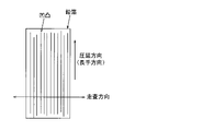
- the rolled lead foil has unevenness parallel to the rolling direction (longitudinal direction), as shown in FIG. Therefore, by measuring the stylus-type surface roughness on the surface of the lead foil with the direction inclined at 90 degrees with respect to the rolling direction as the scanning direction, the unevenness of the lead foil can be measured with high accuracy. Further, it is preferable to measure the stylus surface roughness at a plurality of locations on each of the front surface and the back surface. Further, the measured length l may be 4 mm from any point.
- the present inventors have found that local thinning can be suppressed by making the thickness of the lead foil uniform.
- the maximum valley depth Rv of the lead foil is preferably 2 ⁇ m or less, more preferably 1.5 ⁇ m or less.
- the lead foil is made of lead or a lead alloy containing lead as a main component.
- the lead foil contains Sn, and the Sn content is preferably 0.4% by mass or more and 2% by mass or less.
- Sn content is preferably 0.4% by mass or more and 2% by mass or less.
- the lead foil preferably contains one or more of Ca, Ag and Cu.
- Ca, Ag, and Cu have the effect of uniforming the metal structure of the lead alloy and facilitating control of the maximum valley depth to be shallow when contained in the lead foil.
- the Ca content is more than 0 mass% and 0.1 mass% or less
- the Ag content is more than 0 mass% and 0.05 mass% or less
- the Cu content is more than 0 mass% and 0.05 mass% or less.
- the contents of any component exceeds the above upper limit, the corrosion resistance of the lead foil is reduced.
- the contents of Ca, Ag and Cu are lower than the above lower limits, the lead tends to be deformed, making it difficult to roll the lead foil thinly.
- the lead foil contains Bi, and the content of Bi is more than 0 and 0.004% by mass or less.
- Including Bi in the lead foil has the effect of making the metallographic structure of the lead alloy uniform and facilitating control of the maximum valley depth to be shallow.
- the Bi content exceeds 0.004% by mass, the formability of the lead foil may deteriorate.
- the final plate thickness of the lead foil is thin, there is a high possibility that the poor workability due to the addition of Bi will become apparent.
- the content of each composition in the lead foil is obtained by emission spectroscopic analysis.
- the lead foil according to the present embodiment can be manufactured using rolling rolls whose peripheral side surfaces have been polished in advance during the rolling process. Further, in the polishing of the rolling rolls, for example, mechanical polishing using a whetstone may be performed, or chemical polishing by etching may be performed. Further, chemical polishing by etching may be performed after polishing using a whetstone. Furthermore, the lead foil may be manufactured by polishing the rolled lead foil. Also in this case, the lead foil may be polished by mechanical polishing, chemical polishing, or both mechanical polishing and chemical polishing. In this case, the rolling rolls used for rolling may be ground in advance as described above, or may not be ground in advance.
- the maximum valley depth Rv was specified for both the front surface and the back surface, but the present invention is not limited to such an example.
- the surface specifying the maximum valley depth Rv may be either the front surface or the rear surface. From the viewpoint of making the thickness of the lead foil more uniform, it is preferable to specify the maximum valley depth Rv for both the front surface and the back surface as in the embodiment.
- the positive electrode lead foil 101 and the negative electrode lead foil 102 are the lead foils for specifying the maximum valley depth Rv, but the present invention is not limited to this example.
- the lead foil for specifying the maximum valley depth Rv may be only one of the positive electrode lead foil 101 and the negative electrode lead foil 102 .
- a work roll which is a rolling roll used for rolling, was polished and then rolled using the work roll. Then, for the lead foil after rolling, the maximum valley depth Rv was measured by stylus surface roughness measurement, and the thickness was measured.
- the work roll an iron base material plated with chromium was used.
- the work roll was mechanically polished with a grindstone having a grain size of #80.
- the work roll was mechanically polished with a grindstone having a grain size of #320.
- the work roll was mechanically polished with a grindstone of grain size #320, and then mechanically polished with a grindstone of grain size #500.
- Example 16 the work roll was mechanically polished in the same manner as in Examples 13 to 9 and 13 to 15, and then the work roll was polished using an etchant for chromium (Eclean S-24 manufactured by Sasaki Chemicals Co., Ltd.). Etched (chemically polished).
- Example 17 after mechanical polishing and chemical polishing were performed in the same manner as in Example 16, the rolled lead foil was cut out, and the cut lead foil was immersed in a mixed solution of lactic acid and hydrogen peroxide to perform chemical polishing. rice field.
- the lead foil was similarly rolled under the conditions where the surface of the work roll was roughened and the condition where the Bi content was increased, and the maximum valley depth Rv was measured by stylus surface roughness measurement.
- the surface of the work roll was rubbed with a steel brush to set the maximum valley depth Rv of the surface of the work roll to over 4.0 ⁇ m, and rolling was performed using this work roll.
- rolling was performed using the same work rolls as in Example 1 under the condition that the Bi content was 0.01.
- Example 1-9, 13-15 and Comparative Examples 1-2 the ingot was rolled from 8 mm to 0.25 mm in thickness.
- Example 10 to 12 the ingot was rolled from 8 mm to 0.10 mm in thickness.
- the rolling rate was set to 1 m/min or less and the reduction was set to 0.01 mm/pass or less.
- a tensile test was performed on the prepared lead foil.
- the elongation at break was measured in a direction tilted 90 degrees with respect to the rolling direction (scanning direction for surface roughness measurement shown in FIG. 4).
- the notch effect due to stress concentration at the bottom of the recessed portion is pulled in the direction of 90 degrees with respect to the rolling direction. maximum when
- Table 1 shows the alloy composition of the lead foil, the maximum valley depth Rv, the thickness of the foil, and the results of the tensile test as the results of the example.
- the elongation at break measured by the above method is " ⁇ (Excellent)” when it is 15% or more, and “ ⁇ (Good)” when it is 10% or more and less than 15%.
- 5% or more and less than 10% are shown as “ ⁇ (Fair)”
- the case of less than 5% is shown as "X (Poor)”.
- the maximum valley depth Rv was 4.0 or less, and the tensile test result was 10% or more, which was a good result.
- the maximum valley depth Rv was 4.8 ⁇ m, exceeding the preferred range in the above embodiment, and the tensile test result was less than 5%. This is because growth deformation caused stress concentration at a portion with a low valley depth, that is, a portion with a small thickness, and fracture occurred.
- Comparative Example 2 since the Bi content was large, the formability was poor, and edge cracks occurred at a plate thickness intermediate to the final finished thickness, so rolling was discontinued. In Comparative Example 2, good results were obtained with no cracks up to a plate thickness intermediate to the final finished thickness. From the above results, it was confirmed that the embodiment provides a lead foil and a bipolar lead-acid battery capable of preventing breakage of the lead foil due to growth deformation.
Landscapes
- Chemical & Material Sciences (AREA)
- Engineering & Computer Science (AREA)
- Chemical Kinetics & Catalysis (AREA)
- Electrochemistry (AREA)
- General Chemical & Material Sciences (AREA)
- Materials Engineering (AREA)
- Manufacturing & Machinery (AREA)
- Mechanical Engineering (AREA)
- Metallurgy (AREA)
- Organic Chemistry (AREA)
- Composite Materials (AREA)
- Cell Electrode Carriers And Collectors (AREA)
Priority Applications (4)
| Application Number | Priority Date | Filing Date | Title |
|---|---|---|---|
| JP2023516330A JPWO2022224622A1 (https=) | 2021-04-20 | 2022-03-11 | |
| CN202280029724.1A CN117178390A (zh) | 2021-04-20 | 2022-03-11 | 铅箔以及双极型铅蓄电池 |
| EP22791402.5A EP4329018A1 (en) | 2021-04-20 | 2022-03-11 | Lead foil and bipolar lead-acid battery |
| US18/489,483 US20240047697A1 (en) | 2021-04-20 | 2023-10-18 | Lead Foil And Bipolar Lead Acid Storage Battery |
Applications Claiming Priority (2)
| Application Number | Priority Date | Filing Date | Title |
|---|---|---|---|
| JP2021071370 | 2021-04-20 | ||
| JP2021-071370 | 2021-04-20 |
Related Child Applications (1)
| Application Number | Title | Priority Date | Filing Date |
|---|---|---|---|
| US18/489,483 Continuation US20240047697A1 (en) | 2021-04-20 | 2023-10-18 | Lead Foil And Bipolar Lead Acid Storage Battery |
Publications (1)
| Publication Number | Publication Date |
|---|---|
| WO2022224622A1 true WO2022224622A1 (ja) | 2022-10-27 |
Family
ID=83722878
Family Applications (1)
| Application Number | Title | Priority Date | Filing Date |
|---|---|---|---|
| PCT/JP2022/011072 Ceased WO2022224622A1 (ja) | 2021-04-20 | 2022-03-11 | 鉛箔及びバイポーラ型鉛蓄電池 |
Country Status (5)
| Country | Link |
|---|---|
| US (1) | US20240047697A1 (https=) |
| EP (1) | EP4329018A1 (https=) |
| JP (1) | JPWO2022224622A1 (https=) |
| CN (1) | CN117178390A (https=) |
| WO (1) | WO2022224622A1 (https=) |
Citations (3)
| Publication number | Priority date | Publication date | Assignee | Title |
|---|---|---|---|---|
| JPS4726633A (https=) * | 1971-03-29 | 1972-10-25 | ||
| JP2004158433A (ja) * | 2002-10-18 | 2004-06-03 | Furukawa Battery Co Ltd:The | 鉛蓄電池用基板およびそれを用いた鉛蓄電池 |
| WO2022030416A1 (ja) * | 2020-08-05 | 2022-02-10 | 古河電気工業株式会社 | 鉛合金、鉛蓄電池用正極、鉛蓄電池、及び蓄電システム |
-
2022
- 2022-03-11 JP JP2023516330A patent/JPWO2022224622A1/ja active Pending
- 2022-03-11 CN CN202280029724.1A patent/CN117178390A/zh active Pending
- 2022-03-11 WO PCT/JP2022/011072 patent/WO2022224622A1/ja not_active Ceased
- 2022-03-11 EP EP22791402.5A patent/EP4329018A1/en not_active Withdrawn
-
2023
- 2023-10-18 US US18/489,483 patent/US20240047697A1/en active Pending
Patent Citations (3)
| Publication number | Priority date | Publication date | Assignee | Title |
|---|---|---|---|---|
| JPS4726633A (https=) * | 1971-03-29 | 1972-10-25 | ||
| JP2004158433A (ja) * | 2002-10-18 | 2004-06-03 | Furukawa Battery Co Ltd:The | 鉛蓄電池用基板およびそれを用いた鉛蓄電池 |
| WO2022030416A1 (ja) * | 2020-08-05 | 2022-02-10 | 古河電気工業株式会社 | 鉛合金、鉛蓄電池用正極、鉛蓄電池、及び蓄電システム |
Also Published As
| Publication number | Publication date |
|---|---|
| CN117178390A (zh) | 2023-12-05 |
| EP4329018A1 (en) | 2024-02-28 |
| US20240047697A1 (en) | 2024-02-08 |
| JPWO2022224622A1 (https=) | 2022-10-27 |
Similar Documents
| Publication | Publication Date | Title |
|---|---|---|
| KR102538675B1 (ko) | 전지캔용 니켈 도금 열처리 강판 | |
| US10205135B2 (en) | Steel foil for power storage device container, power storage device container, power storage device, and manufacturing method of steel foil for power storage device container | |
| US7214440B2 (en) | Metallic separator for fuel cell and production method for the same | |
| US10418601B2 (en) | Steel foil for power storage device container, power storage device container, power storage device, and manufacturing method of steel foil for power storage device container | |
| KR20190044017A (ko) | 이차전지 음극 집전체용 압연 동박, 이를 이용한 이차전지 음극 및 이차전지, 및 이차전지 음극 집전체용 압연 동박의 제조 방법 | |
| JP2000323152A (ja) | ステンレス鋼製低温型燃料電池用セパレータ及びその製造方法 | |
| JP2009215604A (ja) | 銅箔とその製造方法 | |
| WO2022224622A1 (ja) | 鉛箔及びバイポーラ型鉛蓄電池 | |
| US20230178712A1 (en) | Lead Alloy, Positive Electrode for Lead Storage Battery, Lead Storage Battery, and Power Storage System | |
| KR102844132B1 (ko) | 니켈 수소 이차 전지 집전체용 Ni 도금강박, 니켈 수소 이차 전지 집전체, 및 니켈 수소 이차 전지 | |
| JP2014091845A (ja) | ニッケルめっき材およびその製造方法 | |
| JP3854464B2 (ja) | アルカリマンガン電池正極缶用Niメッキ鋼板 | |
| WO2022224623A1 (ja) | 鉛箔及びバイポーラ型鉛蓄電池 | |
| JP7474096B2 (ja) | ニッケル水素二次電池集電体用Niめっき鋼箔、ニッケル水素二次電池集電体、及びニッケル水素二次電池 | |
| US7903391B2 (en) | Aluminum electrode plate for electrolytic capacitor | |
| JP7475931B2 (ja) | ニッケル水素二次電池集電体用Niめっき鋼箔、ニッケル水素二次電池集電体、及びニッケル水素二次電池 | |
| WO2023106241A1 (ja) | 銅系線材および半導体デバイス | |
| EP4297132A1 (en) | Current collector steel foil, electrode, and battery | |
| JP2009054421A (ja) | 燃料電池用アルミニウム板及びそれを用いたセパレータ並びにエンドプレート及びそれらを用いた燃料電池並びにそれらの補修方法。 | |
| JP4274737B2 (ja) | 燃料電池用金属製セパレータおよびその製造方法 | |
| JPS61200664A (ja) | アルカリ電池 | |
| WO2025154522A1 (ja) | Snめっき付きクラッド材およびSnめっき付きクラッド材の製造方法 | |
| JP2004071319A (ja) | 燃料電池用金属製セパレータ用素材板およびそれを使用した燃料電池用金属製セパレータ | |
| JP2006117990A (ja) | 複層ステンレス鋼板及びそれを用いた電池ケース | |
| JP2002279999A (ja) | 二次電池集電体用金属箔およびその製造方法 |
Legal Events
| Date | Code | Title | Description |
|---|---|---|---|
| 121 | Ep: the epo has been informed by wipo that ep was designated in this application |
Ref document number: 22791402 Country of ref document: EP Kind code of ref document: A1 |
|
| ENP | Entry into the national phase |
Ref document number: 2023516330 Country of ref document: JP Kind code of ref document: A |
|
| WWE | Wipo information: entry into national phase |
Ref document number: 202327072355 Country of ref document: IN |
|
| WWE | Wipo information: entry into national phase |
Ref document number: 2022791402 Country of ref document: EP |
|
| NENP | Non-entry into the national phase |
Ref country code: DE |
|
| ENP | Entry into the national phase |
Ref document number: 2022791402 Country of ref document: EP Effective date: 20231120 |
|
| WWW | Wipo information: withdrawn in national office |
Ref document number: 2022791402 Country of ref document: EP |