EP4329018A1 - Lead foil and bipolar lead-acid battery - Google Patents
Lead foil and bipolar lead-acid battery Download PDFInfo
- Publication number
- EP4329018A1 EP4329018A1 EP22791402.5A EP22791402A EP4329018A1 EP 4329018 A1 EP4329018 A1 EP 4329018A1 EP 22791402 A EP22791402 A EP 22791402A EP 4329018 A1 EP4329018 A1 EP 4329018A1
- Authority
- EP
- European Patent Office
- Prior art keywords
- lead
- lead foil
- mass
- foil
- bipolar
- Prior art date
- Legal status (The legal status is an assumption and is not a legal conclusion. Google has not performed a legal analysis and makes no representation as to the accuracy of the status listed.)
- Withdrawn
Links
Images

Classifications
-
- H—ELECTRICITY
- H01—ELECTRIC ELEMENTS
- H01M—PROCESSES OR MEANS, e.g. BATTERIES, FOR THE DIRECT CONVERSION OF CHEMICAL ENERGY INTO ELECTRICAL ENERGY
- H01M4/00—Electrodes
- H01M4/02—Electrodes composed of, or comprising, active material
- H01M4/64—Carriers or collectors
- H01M4/66—Selection of materials
- H01M4/68—Selection of materials for use in lead-acid accumulators
- H01M4/685—Lead alloys
-
- C—CHEMISTRY; METALLURGY
- C22—METALLURGY; FERROUS OR NON-FERROUS ALLOYS; TREATMENT OF ALLOYS OR NON-FERROUS METALS
- C22C—ALLOYS
- C22C11/00—Alloys based on lead
- C22C11/06—Alloys based on lead with tin as the next major constituent
-
- H—ELECTRICITY
- H01—ELECTRIC ELEMENTS
- H01M—PROCESSES OR MEANS, e.g. BATTERIES, FOR THE DIRECT CONVERSION OF CHEMICAL ENERGY INTO ELECTRICAL ENERGY
- H01M10/00—Secondary cells; Manufacture thereof
- H01M10/06—Lead-acid accumulators
-
- H—ELECTRICITY
- H01—ELECTRIC ELEMENTS
- H01M—PROCESSES OR MEANS, e.g. BATTERIES, FOR THE DIRECT CONVERSION OF CHEMICAL ENERGY INTO ELECTRICAL ENERGY
- H01M10/00—Secondary cells; Manufacture thereof
- H01M10/06—Lead-acid accumulators
- H01M10/18—Lead-acid accumulators with bipolar electrodes
-
- H—ELECTRICITY
- H01—ELECTRIC ELEMENTS
- H01M—PROCESSES OR MEANS, e.g. BATTERIES, FOR THE DIRECT CONVERSION OF CHEMICAL ENERGY INTO ELECTRICAL ENERGY
- H01M4/00—Electrodes
- H01M4/02—Electrodes composed of, or comprising, active material
- H01M4/14—Electrodes for lead-acid accumulators
-
- H—ELECTRICITY
- H01—ELECTRIC ELEMENTS
- H01M—PROCESSES OR MEANS, e.g. BATTERIES, FOR THE DIRECT CONVERSION OF CHEMICAL ENERGY INTO ELECTRICAL ENERGY
- H01M4/00—Electrodes
- H01M4/02—Electrodes composed of, or comprising, active material
- H01M4/64—Carriers or collectors
- H01M4/66—Selection of materials
- H01M4/665—Composites
- H01M4/667—Composites in the form of layers, e.g. coatings
-
- H—ELECTRICITY
- H01—ELECTRIC ELEMENTS
- H01M—PROCESSES OR MEANS, e.g. BATTERIES, FOR THE DIRECT CONVERSION OF CHEMICAL ENERGY INTO ELECTRICAL ENERGY
- H01M4/00—Electrodes
- H01M4/02—Electrodes composed of, or comprising, active material
- H01M4/64—Carriers or collectors
- H01M4/70—Carriers or collectors characterised by shape or form
- H01M4/72—Grids
- H01M4/73—Grids for lead-acid accumulators, e.g. frame plates
-
- Y—GENERAL TAGGING OF NEW TECHNOLOGICAL DEVELOPMENTS; GENERAL TAGGING OF CROSS-SECTIONAL TECHNOLOGIES SPANNING OVER SEVERAL SECTIONS OF THE IPC; TECHNICAL SUBJECTS COVERED BY FORMER USPC CROSS-REFERENCE ART COLLECTIONS [XRACs] AND DIGESTS
- Y02—TECHNOLOGIES OR APPLICATIONS FOR MITIGATION OR ADAPTATION AGAINST CLIMATE CHANGE
- Y02E—REDUCTION OF GREENHOUSE GAS [GHG] EMISSIONS, RELATED TO ENERGY GENERATION, TRANSMISSION OR DISTRIBUTION
- Y02E60/00—Enabling technologies; Technologies with a potential or indirect contribution to GHG emissions mitigation
- Y02E60/10—Energy storage using batteries
-
- Y—GENERAL TAGGING OF NEW TECHNOLOGICAL DEVELOPMENTS; GENERAL TAGGING OF CROSS-SECTIONAL TECHNOLOGIES SPANNING OVER SEVERAL SECTIONS OF THE IPC; TECHNICAL SUBJECTS COVERED BY FORMER USPC CROSS-REFERENCE ART COLLECTIONS [XRACs] AND DIGESTS
- Y02—TECHNOLOGIES OR APPLICATIONS FOR MITIGATION OR ADAPTATION AGAINST CLIMATE CHANGE
- Y02P—CLIMATE CHANGE MITIGATION TECHNOLOGIES IN THE PRODUCTION OR PROCESSING OF GOODS
- Y02P70/00—Climate change mitigation technologies in the production process for final industrial or consumer products
- Y02P70/50—Manufacturing or production processes characterised by the final manufactured product
Definitions
- the present invention relates to lead foil and a bipolar lead acid storage battery.
- a bipolar lead acid storage battery includes a bipolar electrode including a positive electrode, a negative electrode, and a substrate (bipolar plate), on one surface of which the positive electrode is provided and on the other surface of which the negative electrode is provided.
- a bipolar electrode including a positive electrode, a negative electrode, and a substrate (bipolar plate), on one surface of which the positive electrode is provided and on the other surface of which the negative electrode is provided.
- lead foil is provided on both surfaces of a resin substrate, and a positive electrode and a negative electrode are provided on one surface and the other surface of the substrate, respectively.
- lead foil used for an electrode of a bipolar lead acid storage battery causes growth deformation that expands with long-term use of the battery, and breakage due to the growth deformation sometimes becomes a problem.
- an object of the present invention is to provide lead foil and a bipolar lead acid storage battery capable of preventing breakage of the lead foil due to growth deformation.
- lead foil for a current collector in a bipolar lead acid storage battery in which at least one of a front surface and a back surface has a maximum valley depth Rv of 4 um or less in a profile curve acquired, orthogonally to a rolling direction, by surface roughness measurement with a stylus.
- a bipolar lead acid storage battery in which at least one of positive lead foil and negative lead foil is the above lead foil.
- lead foil and a bipolar lead acid storage battery capable of preventing breakage of the lead foil due to growth deformation.
- the bipolar lead acid storage battery 1 illustrated in FIG. 1 includes a first plate unit in which a negative electrode 110 is fixed to a first plate 11 having a flat plate shape, a second plate unit in which an electrolytic layer 105 is fixed to the inside of a second plate 12 having a frame plate shape, a third plate unit in which a bipolar electrode 130, in which a positive electrode 120 is formed on one surface of a substrate 111 and a negative electrode 110 is formed on the other surface, is fixed to the inside of a third plate 13 having a frame plate shape, and a fourth plate unit in which the positive electrode 120 is fixed to a fourth plate 14 having a flat plate shape.
- the substrate 111 is formed of a thermoplastic resin.
- the second plate units and the third plate units are alternately stacked between the first plate unit and the fourth plate unit to form the bipolar lead acid storage battery 1 having a substantially rectangular parallelepiped shape.
- the number of the stacked second plate units and the number of the stacked third plate units are set such that the storage capacity of the bipolar lead acid storage battery 1 has a desired value.
- a negative terminal 107 is fixed to the first plate 11, and the negative electrode 110 and the negative terminal 107 that are fixed to the first plate 11 are electrically connected.
- a positive terminal 108 is fixed to the fourth plate 14, and the positive electrode 120 and the positive terminal 108 that are fixed to the fourth plate 14 are electrically connected.
- the electrolytic layer 105 is formed of, for example, a glass fiber mat impregnated with an electrolyte containing sulfuric acid.
- the first to fourth plates 11 to 14 are formed of, for example, a known molding resin.
- the first to fourth plates 11 to 14 are fixed to each other by an appropriate method such that the inside is sealed to prevent the electrolyte from flowing out.
- the positive electrode 120 includes positive lead foil 101 made of lead or a lead alloy and disposed on the one surface of the substrate 111, a positive active material layer 103 disposed on the positive lead foil 101, and an adhesive layer 140 disposed between the one surface of the substrate 111 and the positive lead foil 101 to bond the one surface of the substrate 111 to the positive lead foil 101. That is, on the one surface of the substrate 111 (upward-facing surface of the paper in FIGS. 2 and 3 ), the adhesive layer 140, the positive lead foil 101, and the positive active material layer 103 are stacked in this order.
- the negative electrode 110 includes negative lead foil 102 made of lead or a lead alloy and disposed on the other surface of the substrate 111, a negative active material layer 104 disposed on the negative lead foil 102, and an adhesive layer (not illustrated) disposed between the other surface of the substrate 111 and the negative lead foil 102 to bond the other surface of the substrate 111 to the negative lead foil 102.
- These positive electrode 120 and negative electrode 110 are electrically connected by an appropriate method.
- the substrate 111, the positive lead foil 101, the positive active material layer 103, the negative lead foil 102, and the negative active material layer 104 constitute the bipolar electrode 130, as previously described.
- the bipolar electrode is an electrode, a single one of which functions as both a positive electrode and a negative electrode.
- the bipolar lead acid storage battery 1 has a battery configuration in which a plurality of cell members are connected in series by alternately stacking and assembling the cell members in which the electrolytic layer 105 is interposed between the positive electrode 120 and the negative electrode 110.
- the adhesive layer 140 disposed between the one surface of the substrate 111 and the positive lead foil 101 is formed of a cured product of a reaction-curable adhesive that is cured by reaction of a main agent containing an epoxy resin with a curing agent containing an amine compound.
- the lead foil according to the present embodiment is the positive lead foil 101 and the negative lead foil 102 in the above bipolar lead acid storage battery 1, that is, lead foil for a current collector in the bipolar lead acid storage battery 1.
- one surface of the lead foil that faces and is in contact with the positive active material layer 103 or the negative active material layer 104 is defined as a front surface
- the other surface of the lead foil that faces and is in contact with the substrate 111 is defined as a back surface.
- the lead foil is produced to have a predetermined thickness by being rolled with a rolling roll.
- At least one of the front surface and the back surface of the lead foil has a maximum valley depth Rv of 4 um or less in a profile curve acquired, orthogonally to a rolling direction at the time of rolling, by surface roughness measurement with a stylus.
- the surface roughness measurement with a stylus can be performed by the measurement method specified in JIS B 0601:1994.
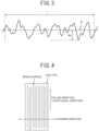
- a profile curve as illustrated in FIG. 3 is acquired.
- 1 is a measurement length
- m is an average line
- Rv is the lowest valley depth (maximum valley depth), all of which are values defined in JIS B 0601:1994.
- the lead foil subjected to rolling processing has irregularities parallel to the rolling direction (longitudinal direction). Therefore, by performing, on the surface of the lead foil, surface roughness measurement with a stylus assuming that a direction orthogonal to the rolling direction is defined as a scanning direction, the irregularities of the lead foil can be accurately measured.
- it is preferable to perform, for each of the front surface and the back surface, the surface roughness measurement with a stylus at multiple locations, and the surface roughness measurement with a stylus may be performed, for example, at ten locations (the number of repetitions N 10).
- the measurement length l may be a length of 4 mm from any place.
- the present inventors investigated and studied on breakage of lead foil due to growth deformation. As a result, it has been confirmed that, in the growth deformation, a portion thinner than the periphery is more easily deformed and local thinning is promoted, so that the lead foil is broken. It has also been confirmed that the breaking due to thinning becomes remarkable when a strain rate is small.
- Such a phenomenon in the lead foil is peculiar to lead that does not cause work hardening, and does not occur in other metals, such as copper and aluminum, used for an electrode.
- a region (local deformation portion) having a small thickness and deformed more than its periphery, is work-hardened more than its periphery. Therefore, deformation resistance is averaged, and uniform deformation is maintained.
- the present inventors have found that local thinning can be suppressed by making the thickness of the lead foil uniform. That is, by setting the maximum valley depth Rv of the lead foil to 4 um or less, the lead foil is uniformly deformed even if the growth deformation occurs, so that breakage due to the growth deformation can be prevented.
- the maximum valley depth Rv of the lead foil is preferably 2 um or less, and more preferably 1.5 um or less. By further reducing the maximum valley depth Rv of the lead foil, breakage due to the growth deformation can be prevented for a longer period of time.
- the lead foil is made of lead or a lead alloy containing lead as a main component. It is preferable that the lead foil contains Sn and the content of Sn is 0.4% by mass or more and 2% by mass or less.
- Sn is contained in the lead foil, the adhesion between the lead foil and the active material can be improved. If the content of Sn is less than 0.4% by mass, the adhesion between the lead foil and the active material is decreased, so that peeling of the active material layer or the like may occur. On the other hand, if the content of Sn is more than 2% by mass, intergranular corrosion susceptibility is increased, so that the lead foil may be easily degraded.
- the lead foil preferably contains at least one type selected from the group consisting of Ca, Ag, and Cu.
- the content of Ca is preferably more than 0% by mass and 0.1% by mass or less
- the content of Ag is preferably more than 0% by mass and 0.05% by mass or less
- the content of Cu is preferably more than 0% by mass and 0.05% by mass or less. If the content of any component exceeds the above upper limit value, the corrosion resistance of the lead foil is decreased.
- the contents of Ca, Ag, and Cu are lower than the above lower limit values, lead is easily deformed, and it is difficult to thinly roll the lead foil.
- the lead foil contains Bi and the content of Bi is more than 0% by mass and 0.004% by mass or less.
- Bi is contained in the lead foil, there is an effect of making the metal structure of a lead alloy uniform and making it easy to control the maximum valley depth to be shallow.
- the content of Bi is more than 0.004% by mass, the moldability of the lead foil may be deteriorated.
- the final plate thickness of the lead foil is thin, there is a high possibility that poor processability due to the addition of Bi may become apparent.
- the content of each composition of the lead foil is determined by an emission spectroscopic analysis method.
- the lead foil according to the present embodiment can be produced using a rolling roll whose circumferential side surface is polished in advance.
- the polishing of the rolling roll for example, mechanical polishing using a grindstone may be performed, or chemical polishing by etching may be performed. Alternatively, chemical polishing by etching may be performed after polishing using a grindstone.
- the lead foil may be produced by polishing the lead foil subjected to rolling processing. Even in this case, mechanical polishing, chemical polishing, or both mechanical polishing and chemical polishing may be performed as the polishing of the lead foil.
- the rolling roll used in the rolling processing may be polished in advance as described above, or may not be polished in advance.
- the maximum valley depth Rv is specified, for example, for both the front surface and the back surface, but the present invention is not limited to such an example.
- the surface, for which the maximum valley depth Rv is specified may be, for example, only one of the front surface and the back surface. From the viewpoint of making the thickness of the lead foil more uniform, it is preferable to specify the maximum valley depth Rv for both the front surface and the back surface as in the embodiment.
- the lead foils for which the maximum valley depth Rv is specified, are the positive lead foil 101 and the negative lead foil 102, but the present invention is not limited to such an example.
- the lead foil, for which the maximum valley depth Rv is specified, may be, for example, only one of the positive lead foil 101 and the negative lead foil 102.
- Examples performed by the present inventors will be described.
- a work roll which was a rolling roll used in rolling, was polished, and then the rolling was performed using this work roll. Then, for the rolled lead foil, the maximum valley depth Rv was measured by surface roughness measurement with a stylus, and the thickness was measured.
- a chrome-plated iron-based base material was used as the work roll.
- Example 1 the work roll was mechanically polished with a grindstone having a grain size of #80.
- Example 2 and 11 the work roll was mechanically polished with a grindstone having a grain size of #320.
- Examples 13 to 9 and 13 to 15 the work roll was mechanically polished with a grindstone having a grain size of #320, and then the work roll was mechanically polished with a grindstone having a grain size of #500.
- Example 16 after the work roll was mechanical polished similarly to Examples 13 to 9 and 13 to 15, the work roll was etched (chemically polished) using an etching liquid for chromium (S-CLEAN S-24 manufactured by SASAKI CHEMICAL CO., LTD.).
- Example 17 after mechanical polishing and chemical polishing were performed similarly to Example 16, the rolled lead foil was cut out, and the cut out lead foil was immersed in a mixed liquid of lactic acid and hydrogen peroxide to perform chemical polishing.
- the lead foil was also similarly rolled under the condition of making the surface of the work roll coarse or the condition of increasing the content of Bi, and the maximum valley depth Rv was measured by surface roughness measurement with a stylus.
- the surface of the work roll was rubbed with a steel brush to set the maximum valley depth Rv of the surface of the work roll to more than 4.0 um, and the rolling was performed using this work roll.
- the rolling was performed using a work roll similarly to that in Example 1 under a condition in which the content of Bi was 0.01.
- Example 1 Furthermore, in Examples 1 to 9 and 13 to 15 and Comparative Example 1 to 2, an ingot having a thickness of 8 mm was rolled until the thickness became 0.25 mm. In Examples 10 to 12, an ingot having a thickness of 8 mm was rolled until the thickness became 0.10 mm. In Example 1, the surface roughness was small and slippage was likely to occur during the rolling, so that the rolling rate was set to 1 m/min or less and the reduction was set to 0.01 mm/pass or less.
- the produced lead foil was subjected to a tensile test.
- a breaking elongation in a direction orthogonal to the rolling direction (scanning direction in the surface roughness measurement illustrated in FIG. 4 ) was measured. Since groove-shaped irregularities parallel to the longitudinal direction are formed on the rolled surface, a notch effect due to stress concentration on the bottom of the recess is maximized when the surface is pulled in the direction orthogonal to the rolling direction.
- the alloy components of the lead foils, the maximum valley depths Rv, the thicknesses of the foils, and the test results of the tensile test are shown in Table 1.
- Table 1 as the results of the tensile test, the case where the breaking elongation measured by the above method is 15% or more is indicated as “ ⁇ (Excellent)", the case where the breaking elongation is 10% or more and less than 15% is indicated as “o (Good)", the case where the breaking elongation is 5% or more and less than 10% is indicated as " ⁇ (Fair)”, and the case where the breaking elongation is less than 5% is indicated as " ⁇ (Poor)”.
- the maximum valley depths Rv were all 4.0 or less, and the results of the tensile test were also 10% or more, which were favorable.
- the maximum valley depth Rv was 4.8 ⁇ m, which exceeded the preferable range in the above embodiment, and the result of the tensile test was also less than 5%. This is because stress concentration occurred at a portion having a low valley depth, that is, a portion having a small thickness due to the growth deformation, so that breakage occurred.
- the amount of Bi was large, so that moldability was poor and edge cracking occurred at an intermediate plate thickness to the final finished thickness, and therefore the rolling was interrupted.
Landscapes
- Chemical & Material Sciences (AREA)
- Engineering & Computer Science (AREA)
- Chemical Kinetics & Catalysis (AREA)
- Electrochemistry (AREA)
- General Chemical & Material Sciences (AREA)
- Materials Engineering (AREA)
- Manufacturing & Machinery (AREA)
- Mechanical Engineering (AREA)
- Metallurgy (AREA)
- Organic Chemistry (AREA)
- Composite Materials (AREA)
- Cell Electrode Carriers And Collectors (AREA)
Applications Claiming Priority (2)
| Application Number | Priority Date | Filing Date | Title |
|---|---|---|---|
| JP2021071370 | 2021-04-20 | ||
| PCT/JP2022/011072 WO2022224622A1 (ja) | 2021-04-20 | 2022-03-11 | 鉛箔及びバイポーラ型鉛蓄電池 |
Publications (1)
| Publication Number | Publication Date |
|---|---|
| EP4329018A1 true EP4329018A1 (en) | 2024-02-28 |
Family
ID=83722878
Family Applications (1)
| Application Number | Title | Priority Date | Filing Date |
|---|---|---|---|
| EP22791402.5A Withdrawn EP4329018A1 (en) | 2021-04-20 | 2022-03-11 | Lead foil and bipolar lead-acid battery |
Country Status (5)
| Country | Link |
|---|---|
| US (1) | US20240047697A1 (https=) |
| EP (1) | EP4329018A1 (https=) |
| JP (1) | JPWO2022224622A1 (https=) |
| CN (1) | CN117178390A (https=) |
| WO (1) | WO2022224622A1 (https=) |
Family Cites Families (3)
| Publication number | Priority date | Publication date | Assignee | Title |
|---|---|---|---|---|
| JPS5038171B1 (https=) * | 1971-03-29 | 1975-12-08 | ||
| JP4274873B2 (ja) * | 2002-10-18 | 2009-06-10 | 古河電池株式会社 | 鉛蓄電池用基板およびそれを用いた鉛蓄電池 |
| WO2022030416A1 (ja) * | 2020-08-05 | 2022-02-10 | 古河電気工業株式会社 | 鉛合金、鉛蓄電池用正極、鉛蓄電池、及び蓄電システム |
-
2022
- 2022-03-11 JP JP2023516330A patent/JPWO2022224622A1/ja active Pending
- 2022-03-11 CN CN202280029724.1A patent/CN117178390A/zh active Pending
- 2022-03-11 WO PCT/JP2022/011072 patent/WO2022224622A1/ja not_active Ceased
- 2022-03-11 EP EP22791402.5A patent/EP4329018A1/en not_active Withdrawn
-
2023
- 2023-10-18 US US18/489,483 patent/US20240047697A1/en active Pending
Also Published As
| Publication number | Publication date |
|---|---|
| CN117178390A (zh) | 2023-12-05 |
| US20240047697A1 (en) | 2024-02-08 |
| JPWO2022224622A1 (https=) | 2022-10-27 |
| WO2022224622A1 (ja) | 2022-10-27 |
Similar Documents
| Publication | Publication Date | Title |
|---|---|---|
| US7214440B2 (en) | Metallic separator for fuel cell and production method for the same | |
| KR101507940B1 (ko) | 고분자 연료전지 분리판용 스테리인스강 제조방법 | |
| KR101798406B1 (ko) | 연료전지 분리판용 스테인리스강 및 이의 제조 방법 | |
| JP5908194B1 (ja) | 蓄電デバイス容器用鋼箔、蓄電デバイス用容器及び蓄電デバイス、並びに蓄電デバイス容器用鋼箔の製造方法 | |
| KR20190044017A (ko) | 이차전지 음극 집전체용 압연 동박, 이를 이용한 이차전지 음극 및 이차전지, 및 이차전지 음극 집전체용 압연 동박의 제조 방법 | |
| EP3125341B1 (en) | Lead storage cell and electrode collector for lead storage cell | |
| EP3395990A1 (en) | Stainless steel for polymer fuel cell separation plate having improved hydrophilicity and contact resistance and method for manufacturing same | |
| KR20150138052A (ko) | 전지 집전체용 클래드재 및 전극 | |
| EP4329018A1 (en) | Lead foil and bipolar lead-acid battery | |
| US20230170464A1 (en) | Lead Alloy, Positive Electrode for Lead Storage Battery, Lead Storage Battery, and Power Storage System | |
| US7049022B2 (en) | Metal separator for fuel cell and production method therefor | |
| US6620551B1 (en) | Positive plate current collector for lead storage battery and lead storage battery comprising the same | |
| EP3904565A1 (en) | Ni-plated steel sheet having excellent post-processing corrosion resistance and production method therefor | |
| DE10297507T5 (de) | Metallischer Separator für Brennstoffzelle und Herstellungsverfahren für denselben | |
| US20170077481A1 (en) | Lead material for battery and method for manufacturing lead material for battery | |
| EP4329019A1 (en) | Lead foil and bipolar lead-acid battery | |
| US9059468B2 (en) | Positive electrode collector for lead acid storage battery and method for producing the same | |
| US7903391B2 (en) | Aluminum electrode plate for electrolytic capacitor | |
| EP3719894A1 (en) | Clad material for battery current collector and manufacturing method of clad material for battery current collector | |
| DE10297495B4 (de) | Herstellungsverfahren für einen Metallseparator einer Brennstoffzelle | |
| EP0402514B1 (de) | Sinterfolien-Elektrode für Nickel-Cadmium-Akkumulatoren und Verfahren zur Herstellung der Elektrode | |
| EP1615277A1 (en) | Method of producing lattice body for lead storage battery, and lead storage battery | |
| DE10297620B4 (de) | Brennstoffzelle | |
| US20240021841A1 (en) | Current Collector Sheet For Lead-Acid Storage Battery, Lead-Acid Storage Battery, And Bipolar Lead-Acid Storage Battery | |
| US20240250312A1 (en) | Bipolar Storage Battery, Method For Manufacturing Bipolar Storage Battery, And Bipolar Lead-Acid Storage Battery |
Legal Events
| Date | Code | Title | Description |
|---|---|---|---|
| STAA | Information on the status of an ep patent application or granted ep patent |
Free format text: STATUS: THE INTERNATIONAL PUBLICATION HAS BEEN MADE |
|
| PUAI | Public reference made under article 153(3) epc to a published international application that has entered the european phase |
Free format text: ORIGINAL CODE: 0009012 |
|
| STAA | Information on the status of an ep patent application or granted ep patent |
Free format text: STATUS: REQUEST FOR EXAMINATION WAS MADE |
|
| 17P | Request for examination filed |
Effective date: 20231116 |
|
| AK | Designated contracting states |
Kind code of ref document: A1 Designated state(s): AL AT BE BG CH CY CZ DE DK EE ES FI FR GB GR HR HU IE IS IT LI LT LU LV MC MK MT NL NO PL PT RO RS SE SI SK SM TR |
|
| DAV | Request for validation of the european patent (deleted) | ||
| DAX | Request for extension of the european patent (deleted) | ||
| STAA | Information on the status of an ep patent application or granted ep patent |
Free format text: STATUS: THE APPLICATION HAS BEEN WITHDRAWN |
|
| 18W | Application withdrawn |
Effective date: 20250710 |