WO2022215631A1 - 軸封装置 - Google Patents
軸封装置 Download PDFInfo
- Publication number
- WO2022215631A1 WO2022215631A1 PCT/JP2022/016110 JP2022016110W WO2022215631A1 WO 2022215631 A1 WO2022215631 A1 WO 2022215631A1 JP 2022016110 W JP2022016110 W JP 2022016110W WO 2022215631 A1 WO2022215631 A1 WO 2022215631A1
- Authority
- WO
- WIPO (PCT)
- Prior art keywords
- seal ring
- sliding surface
- ring
- shaft
- sealing device
- Prior art date
- Legal status (The legal status is an assumption and is not a legal conclusion. Google has not performed a legal analysis and makes no representation as to the accuracy of the status listed.)
- Ceased
Links
Images


Classifications
-
- F—MECHANICAL ENGINEERING; LIGHTING; HEATING; WEAPONS; BLASTING
- F16—ENGINEERING ELEMENTS AND UNITS; GENERAL MEASURES FOR PRODUCING AND MAINTAINING EFFECTIVE FUNCTIONING OF MACHINES OR INSTALLATIONS; THERMAL INSULATION IN GENERAL
- F16J—PISTONS; CYLINDERS; SEALINGS
- F16J15/00—Sealings
- F16J15/16—Sealings between relatively-moving surfaces
- F16J15/34—Sealings between relatively-moving surfaces with slip-ring pressed against a more or less radial face on one member
- F16J15/3464—Mounting of the seal
-
- F—MECHANICAL ENGINEERING; LIGHTING; HEATING; WEAPONS; BLASTING
- F16—ENGINEERING ELEMENTS AND UNITS; GENERAL MEASURES FOR PRODUCING AND MAINTAINING EFFECTIVE FUNCTIONING OF MACHINES OR INSTALLATIONS; THERMAL INSULATION IN GENERAL
- F16J—PISTONS; CYLINDERS; SEALINGS
- F16J15/00—Sealings
- F16J15/16—Sealings between relatively-moving surfaces
- F16J15/18—Sealings between relatively-moving surfaces with stuffing-boxes for elastic or plastic packings
- F16J15/24—Sealings between relatively-moving surfaces with stuffing-boxes for elastic or plastic packings with radially or tangentially compressed packing
-
- B—PERFORMING OPERATIONS; TRANSPORTING
- B63—SHIPS OR OTHER WATERBORNE VESSELS; RELATED EQUIPMENT
- B63H—MARINE PROPULSION OR STEERING
- B63H23/00—Transmitting power from propulsion power plant to propulsive elements
- B63H23/32—Other parts
- B63H23/321—Bearings or seals specially adapted for propeller shafts
-
- F—MECHANICAL ENGINEERING; LIGHTING; HEATING; WEAPONS; BLASTING
- F16—ENGINEERING ELEMENTS AND UNITS; GENERAL MEASURES FOR PRODUCING AND MAINTAINING EFFECTIVE FUNCTIONING OF MACHINES OR INSTALLATIONS; THERMAL INSULATION IN GENERAL
- F16J—PISTONS; CYLINDERS; SEALINGS
- F16J15/00—Sealings
- F16J15/002—Sealings comprising at least two sealings in succession
- F16J15/008—Sealings comprising at least two sealings in succession with provision to put out of action at least one sealing; One sealing sealing only on standstill; Emergency or servicing sealings
-
- F—MECHANICAL ENGINEERING; LIGHTING; HEATING; WEAPONS; BLASTING
- F16—ENGINEERING ELEMENTS AND UNITS; GENERAL MEASURES FOR PRODUCING AND MAINTAINING EFFECTIVE FUNCTIONING OF MACHINES OR INSTALLATIONS; THERMAL INSULATION IN GENERAL
- F16J—PISTONS; CYLINDERS; SEALINGS
- F16J15/00—Sealings
- F16J15/16—Sealings between relatively-moving surfaces
- F16J15/164—Sealings between relatively-moving surfaces the sealing action depending on movements; pressure difference, temperature or presence of leaking fluid
-
- F—MECHANICAL ENGINEERING; LIGHTING; HEATING; WEAPONS; BLASTING
- F16—ENGINEERING ELEMENTS AND UNITS; GENERAL MEASURES FOR PRODUCING AND MAINTAINING EFFECTIVE FUNCTIONING OF MACHINES OR INSTALLATIONS; THERMAL INSULATION IN GENERAL
- F16J—PISTONS; CYLINDERS; SEALINGS
- F16J15/00—Sealings
- F16J15/16—Sealings between relatively-moving surfaces
- F16J15/34—Sealings between relatively-moving surfaces with slip-ring pressed against a more or less radial face on one member
- F16J15/3436—Pressing means
- F16J15/3448—Pressing means the pressing force resulting from fluid pressure
-
- F—MECHANICAL ENGINEERING; LIGHTING; HEATING; WEAPONS; BLASTING
- F16—ENGINEERING ELEMENTS AND UNITS; GENERAL MEASURES FOR PRODUCING AND MAINTAINING EFFECTIVE FUNCTIONING OF MACHINES OR INSTALLATIONS; THERMAL INSULATION IN GENERAL
- F16J—PISTONS; CYLINDERS; SEALINGS
- F16J15/00—Sealings
- F16J15/16—Sealings between relatively-moving surfaces
- F16J15/34—Sealings between relatively-moving surfaces with slip-ring pressed against a more or less radial face on one member
- F16J15/3436—Pressing means
- F16J15/3456—Pressing means without external means for pressing the ring against the face, e.g. slip-ring with a resilient lip
-
- B—PERFORMING OPERATIONS; TRANSPORTING
- B63—SHIPS OR OTHER WATERBORNE VESSELS; RELATED EQUIPMENT
- B63H—MARINE PROPULSION OR STEERING
- B63H23/00—Transmitting power from propulsion power plant to propulsive elements
- B63H23/32—Other parts
- B63H23/321—Bearings or seals specially adapted for propeller shafts
- B63H2023/327—Sealings specially adapted for propeller shafts or stern tubes
-
- B—PERFORMING OPERATIONS; TRANSPORTING
- B63—SHIPS OR OTHER WATERBORNE VESSELS; RELATED EQUIPMENT
- B63H—MARINE PROPULSION OR STEERING
- B63H23/00—Transmitting power from propulsion power plant to propulsive elements
- B63H23/32—Other parts
- B63H23/36—Shaft tubes
-
- F—MECHANICAL ENGINEERING; LIGHTING; HEATING; WEAPONS; BLASTING
- F16—ENGINEERING ELEMENTS AND UNITS; GENERAL MEASURES FOR PRODUCING AND MAINTAINING EFFECTIVE FUNCTIONING OF MACHINES OR INSTALLATIONS; THERMAL INSULATION IN GENERAL
- F16J—PISTONS; CYLINDERS; SEALINGS
- F16J15/00—Sealings
- F16J15/16—Sealings between relatively-moving surfaces
- F16J15/34—Sealings between relatively-moving surfaces with slip-ring pressed against a more or less radial face on one member
- F16J15/3404—Sealings between relatively-moving surfaces with slip-ring pressed against a more or less radial face on one member and characterised by parts or details relating to lubrication, cooling or venting of the seal
Definitions
- the present invention relates to a shaft sealing device for sealing a rotating shaft.
- a mechanical seal comprising a pair of annular sliding parts that rotate relatively and the sliding surfaces slide against each other is used. It is known to use a lip seal that rotates and slides relative to the sliding surface of the shaft or housing.
- the shaft seal device used in the ship propulsion device shown in Patent Document 1 has a case attached to a stern tube through which a rotating shaft having a propulsion propeller is inserted. It is arranged so as to be slidable from the inside.
- the seal ring for regular use is attached to the stepped portion on one axial end side of the clamp ring fixed to the rotary shaft, and a spare seal ring is attached to the stepped portion on the other axial end side of the clamp ring.
- the lip seal is arranged on the outer side of the normal seal ring, and when seawater flows outward, the lip seal does not come into contact with the rotating shaft and the normal seal seals the seawater. By stopping the flow, it comes into contact with the rotating shaft and the seawater can be sealed by the lip seal.
- the sealing performance of the commonly used seal ring may deteriorate due to wear over time, and the sealed fluid may leak into the space inside the ship.
- the rotation of the rotating shaft is stopped and seawater in the case is sealed from leakage to the inboard space side by the lip seal.
- Repair can be performed by removing the seal ring from the clamp ring and attaching a spare seal ring to the stepped portion at one end of the clamp ring in the axial direction. After that, by rotating the rotary shaft and allowing seawater to flow outside the ship, the seawater is sealed by a spare seal ring.
- the present invention has been made with a focus on such problems, and an object of the present invention is to provide a shaft seal device capable of easily repairing the leakage of the sealed fluid into the space on the leakage side.
- the shaft sealing device of the present invention includes: A mating ring that has a sliding surface and is attached to a case through which a rotating shaft is inserted; and a conventional seal that has a sliding surface that slides on the sliding surface of the mating ring and is attached to the rotating shaft A shaft seal device that seals a sealed fluid with a ring and sliding surfaces thereof, The shaft seal device is attached to the rotating shaft on the side opposite to the fluid to be sealed in the axial direction with respect to the sliding surface of the mating ring and the sliding surface of the conventional seal ring, and faces the fluid to be sealed in the axial direction. Equipped with a spare seal ring having a sliding surface that The spare seal ring is axially movable toward the fluid to be sealed.
- the spare seal ring in an emergency when the normal seal ring fails, the spare seal ring can be moved toward the fluid to be sealed, so that the fluid to be sealed can be sealed by the spare seal ring. , it is possible to easily repair the leakage of the sealed fluid to the space on the leakage side.
- the spare seal ring may be attached to the rotating shaft by tightening means capable of adjusting tightening force. According to this, by loosening the tightening means, the spare seal ring can be easily moved along the rotary shaft, and by tightening the tightening means, the spare seal ring can be fixed to the rotary shaft. can.
- the regular seal ring and the spare seal ring may be the same part and may be reversed to each other. According to this, since the seal ring for regular use and the seal ring for spare use are the same part, the structure is simple and installation errors are less likely to occur.
- a channel for supplying a sealed fluid from the outside may be connected to the sealed fluid side space inside the case where the conventional seal ring is arranged. According to this, the flow of the sealed fluid is generated in the vicinity of the mating ring and the common seal ring, and it is possible to suppress the retention of contaminants in the vicinity of the sliding surface of the mating ring and the common seal ring. Therefore, even if there is a problem with the regular seal ring and contamination is likely to occur in a relatively large amount, contamination will not enter between the sliding surface of the spare seal ring and another sliding surface of the mating ring. can be suppressed.
- the shaft sealing device may be a water-lubricated stern tube shaft sealing device. According to this, it is possible to suppress intrusion of outboard water into the ship in an emergency.
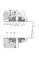
- FIG. 1 is a cross-sectional view of a shaft sealing device in Embodiment 1 according to the present invention
- FIG. 1 is an enlarged cross-sectional view of a main portion of a shaft sealing device according to Embodiment 1 of the present invention
- FIG. 7 is an enlarged cross-sectional view of a main portion of a shaft sealing device according to Embodiment 2 of the present invention
- FIG. 1 A shaft sealing device according to Embodiment 1 will be described with reference to FIGS. 1 and 2.
- FIG. Hereinafter, the left and right sides of FIG. 1 will be described as the left and right sides of the shaft sealing device.
- the side on which the spare seal ring 7 is arranged will be described as the right side, and the opposite side as the left side.
- the shaft sealing device 1 is a water-lubricated stern tube shaft sealing device applied inside a propulsion device as a space S2 on the leakage side of a ship. It seals the rotating shaft 3 penetrating through.
- the shaft seal device 1 may be applied not only to ships but also to rotary machines such as automobiles and general industrial machines.
- a propeller for propulsion is attached to the outboard end of the rotary shaft 3, that is, the axial left end (not shown), and a stern tube bearing supporting the rotary shaft 3 is arranged in the vicinity of the propeller. (not shown).
- the shaft sealing device 1 is mainly composed of a case 4, a mating ring 5, a seal ring 6, and a spare seal ring 7.
- the case 4 has a flanged cylindrical shape including a tubular portion 40 extending in the outboard direction and a flange 41 extending radially outward from the axial right end portion of the tubular portion 40 .
- the tubular portion 40 of the case 4 is fitted inside the joint hose 20 and fixed by the clamping ring 21 .
- the axial right end of the housing 2 is fitted in a joint hose 20 and fixed by a clamping ring 21 .
- a through hole 42 is formed through the case 4 in the axial direction.
- the through hole 42 includes a small diameter hole portion 43 extending axially rightward from the axial left end surface of the cylindrical portion 40 and a large diameter hole portion extending axially rightward and defining a space S1 on the sealed fluid side. 44 , and the small diameter hole portion 43 and the large diameter hole portion 44 are connected to an annular inner end surface 49 extending in the radial direction.
- a plurality of grooves 45 are formed in the cylindrical portion 40 to communicate with the space S1 and the space S2 on the outer side of the ship relative to the case 4, and the right end surface of the groove 45 extends rightward. It becomes the tapered surface 45a which expands in diameter.
- the case 4 is formed with a communication hole 46 that communicates with the outer diameter side and the inner diameter side of the flange 41 formed at the right end in the axial direction, and the inner diameter side of the communication hole 46 communicates with the space S1.
- the mating ring 5 is an annular plate member made of stainless steel having a through-flow passage 50 passing through it in the axial direction. It is a sliding surface 51 that slides, and the inner diameter side end portion of the right end surface in the axial direction is a sliding surface 52 as another sliding surface on which the sliding surfaces 72a and 73a of the spare seal ring 7 can slide. It has become.
- the mating ring 5 is not limited to stainless steel.
- the mating ring 5 has a plurality of shaft holes 53 equally distributed at the outer diameter side end, and a shaft hole 47 axially penetrating the flange 41 of the case 4, and a washer W is inserted into the bolt B. It is attached to the case 4 by inserting the male screw portion Ba and screwing the double nuts N1 and N2.
- the left axial end portion 60b of the seal ring 6 abuts against the inner end surface 49 of the case 4 and slides on the sliding surfaces 62a and 62a of the seal ring 6. It is assembled to the case 4 in a state in which the sliding surface 51 is in surface contact with the 63a so as to be relatively slidable.
- the axial left end portion 60b of the seal ring 6 and the inner end surface 49 of the case 4 may be slightly separated from each other when the shaft sealing device 1 is used.
- an O-ring P is arranged in an annular groove 48 recessed toward the axial left side from the axial right end face of the flange 41 of the case 4. Seawater introduced into the through hole 42 is prevented from leaking inside the ship.
- the commonly used seal ring 6 is made of nitrile rubber and has a cylindrical mounting portion 60 and a large-diameter sealing portion 61 extending radially outward from the mounting portion.
- a thin lip 62 that curves and obliquely extends toward the outer diameter direction is provided on the inner diameter side of 61, and a support leg 63 that is thicker than the lip 62 on the outer diameter side of the lip 62 is provided. formed.
- the commonly used seal ring 6 is not limited to be made of nitrile rubber.
- the axial right end surface of the lip 62 is a sliding surface 62a
- the axial right end surface of the support leg 63 is a sliding surface 63a. Since the support leg 63 mainly receives the force in the axial direction, the lip 62 is likely to exhibit sealing performance.
- a plurality of communication grooves 63b are equally arranged in the support leg 63 and communicate with each other in the radial direction at the right end portion in the axial direction. are in communication.
- the common seal ring 6 is mounted on the rotating shaft 3 and fixed to the rotating shaft 3 by fitting the garter spring 8 into an annular groove 60 a recessed on the outer diameter side of the mounting portion 60 . there is Further, the commonly used seal ring 6 is arranged in the large diameter hole portion 44 of the case 4 .
- the spare seal ring 7 has the same configuration as the seal ring 6, and is arranged opposite to the seal ring 6 by reversing it. For convenience of explanation, common explanations are omitted.
- seawater delivered from outside the ship as a sealed fluid delivered by a pump passes through the connector C, the communication hole 46 of the case 4, and is introduced into the through hole 42 and the space S1. be done.
- seawater passes through the communication holes 46 and the through holes 42 and is discharged overboard.
- part of the seawater flows into and out of the annular groove 64 through the communication groove 63b of the seal ring 6, as indicated by the black arrows in FIG.
- the seawater in the annular groove 64 presses the lip 62 of the common seal ring 6 toward the mating ring 5, and the sliding surface 62a of the lip 62 and the sliding surface 51 of the mating ring 5 are in close contact. is protected.
- the axial left end portion 60b of the common seal ring 6 contacts the inner end surface 49 of the case 4, thereby Since the seal ring 6 is restricted from moving excessively to the left in the axial direction, the contact state between the sliding surface 62a of the lip 62 and the sliding surface 51 of the mating ring 5 can be maintained.
- the support leg 63 with high rigidity receives the force mainly, and the lip 62 of the commonly used seal ring 6 moves toward the annular groove 64 side. Since the sliding surface 62a of the lip 62 and the sliding surface 51 of the mating ring 5 are kept in close contact with each other, they are easily deformed.
- seawater introduced into the through hole 42 due to malfunctions such as wear and aging of the seal ring 6 for regular use passes through the through channel 50 of the mating ring 5 and enters the space S3 side. Describe the leaking state.
- the garter spring 9 is expanded in the outer diameter direction to loosen the tightening force of the rotating shaft 3 applied to the spare seal ring 7, and the spare seal ring 7 is released as indicated by the white arrow in FIG. to the left in the axial direction (that is, to the sealed fluid side) to bring the sliding surfaces 72a and 73a of the spare seal ring 7 into close contact with the sliding surface 52 of the mating ring 5. Adjust the mounting position in the axial direction so as to approach the mating ring 5.
- the spare seal ring 7 is spaced apart from the mating ring 5 in the axial direction and is more axially resistant than the sliding surface 51 of the mating ring 5 and the sliding surfaces 61 a and 63 a of the seal ring 6 . Located on the sealing fluid side.
- the garter spring 9 is fitted again to the annular groove 70a of the spare seal ring 7, and the spare seal ring 7 is tightened and fixed to the rotary shaft 3 to complete the repair work.
- the spare seal ring 7 can be easily moved and fixed by using the garter spring 9 as a tightening means.
- the spare seal ring 7 is simply moved in the axial direction without being expanded, emergency repair work is easy.
- the sliding surface 51 of the mating ring 5 and the sliding surfaces 61a and 63a of the seal ring 6 are maintained in a state of relative rotation and sliding.
- the spare seal ring 170 of the second embodiment has a substantially U-shape on the inner diameter side of the sealing portion 171. More specifically, the auxiliary seal ring 170 extends in the outer diameter direction, is folded back, and then extends in the inner diameter direction and slightly leftward. A thin lip 172 extending obliquely is formed, and is different in shape and extending direction from the lip 72 of the first embodiment.
- the tip of the lip 172 receives force from the sealed fluid toward the sliding surface 52, and the sliding surface 172a provides excellent sealing performance.
- the lip 172 has a U-shape, it may have a shape extending obliquely from the sealing portion toward the inner diameter and to the left.
- the common seal ring and the spare seal ring are both lip-type seal rings. may exist, and may be changed as appropriate.
- the common seal ring and the spare seal ring have the same configuration, but the configuration is not limited to this, and the seal rings may have different shapes.
- the normal seal ring and the spare seal ring are fixed directly to the rotating shaft. It may be fixed to the rotary shaft as long as it is rotatable with the rotary shaft.
- the spare seal ring can be moved with a small force together with the sleeve by loosening the fixing means to the rotary shaft at the time of repair, so the repair work is simple.
- the seal ring for normal use and the seal ring for spare have been described as being formed in a continuous annular shape, but this is not the only option. may be composed of
- the tightening means is a garter spring. well, and may be changed as appropriate.
Landscapes
- Engineering & Computer Science (AREA)
- General Engineering & Computer Science (AREA)
- Mechanical Engineering (AREA)
- Chemical & Material Sciences (AREA)
- Combustion & Propulsion (AREA)
- Ocean & Marine Engineering (AREA)
- Physics & Mathematics (AREA)
- Fluid Mechanics (AREA)
- Sealing Devices (AREA)
- Sealing With Elastic Sealing Lips (AREA)
Priority Applications (4)
| Application Number | Priority Date | Filing Date | Title |
|---|---|---|---|
| JP2023512986A JP7777124B2 (ja) | 2021-04-08 | 2022-03-30 | 軸封装置 |
| EP22784615.1A EP4321778A4 (en) | 2021-04-08 | 2022-03-30 | SHAFT SEALING DEVICE |
| CN202280026159.3A CN117203455A (zh) | 2021-04-08 | 2022-03-30 | 轴封装置 |
| US18/285,487 US12442450B2 (en) | 2021-04-08 | 2022-03-30 | Shaft sealing device |
Applications Claiming Priority (2)
| Application Number | Priority Date | Filing Date | Title |
|---|---|---|---|
| JP2021-065771 | 2021-04-08 | ||
| JP2021065771 | 2021-04-08 |
Publications (1)
| Publication Number | Publication Date |
|---|---|
| WO2022215631A1 true WO2022215631A1 (ja) | 2022-10-13 |
Family
ID=83546084
Family Applications (1)
| Application Number | Title | Priority Date | Filing Date |
|---|---|---|---|
| PCT/JP2022/016110 Ceased WO2022215631A1 (ja) | 2021-04-08 | 2022-03-30 | 軸封装置 |
Country Status (5)
| Country | Link |
|---|---|
| US (1) | US12442450B2 (https=) |
| EP (1) | EP4321778A4 (https=) |
| JP (1) | JP7777124B2 (https=) |
| CN (1) | CN117203455A (https=) |
| WO (1) | WO2022215631A1 (https=) |
Cited By (1)
| Publication number | Priority date | Publication date | Assignee | Title |
|---|---|---|---|---|
| WO2025047568A1 (ja) * | 2023-09-01 | 2025-03-06 | イーグル工業株式会社 | 軸封装置 |
Families Citing this family (1)
| Publication number | Priority date | Publication date | Assignee | Title |
|---|---|---|---|---|
| CN119348800B (zh) * | 2024-12-26 | 2025-04-22 | 天津水动力科技有限公司 | 一种海底作业用水下推进器密封结构 |
Citations (5)
| Publication number | Priority date | Publication date | Assignee | Title |
|---|---|---|---|---|
| JPS6166266U (https=) * | 1984-10-05 | 1986-05-07 | ||
| JPS6432985U (https=) | 1987-08-24 | 1989-03-01 | ||
| JPH02124374U (https=) | 1989-03-23 | 1990-10-12 | ||
| JP2000065219A (ja) * | 1998-08-18 | 2000-03-03 | Eagle Ind Co Ltd | 油潤滑式船尾管軸受の船首側軸封装置 |
| JP2020506348A (ja) * | 2017-02-09 | 2020-02-27 | イーグルブルクマン ジャーマニー ゲセルシャフト ミト ベシュレンクテル ハフツング ウント コンパニー コマンディトゲゼルシャフト | セーフティシールを含むメカニカルシールアセンブリ |
Family Cites Families (28)
| Publication number | Priority date | Publication date | Assignee | Title |
|---|---|---|---|---|
| DE1425175A1 (de) * | 1963-07-23 | 1969-01-02 | Ziller Dr Ing E H Hans | Waelzlagerabdichtung mit einer oder mehreren Dichtscheiben |
| DE1910835A1 (de) * | 1969-03-04 | 1970-09-17 | Ostermann & Co | Dichtungsanordnung fuer Schiffspropellerwellen od.dgl. |
| DE1913397B2 (de) | 1969-03-17 | 1974-06-20 | Feodor Burgmann Jun. Asbest- Und Packungswerk, 8190 Wolfratshausen | Gleitringdichtung mit Schraubengangpumpe |
| US3632117A (en) | 1969-05-15 | 1972-01-04 | Westinghouse Electric Corp | Seal lift-off mechanism |
| US3601412A (en) * | 1970-02-27 | 1971-08-24 | Forsheda Gummifabrik Ab | Arrangement for mounting and axially fixing a shaft seal |
| US3703296A (en) * | 1970-05-20 | 1972-11-21 | Forsheda Gummifabrik Ab | Sealing between a rotary and a stationary member |
| US3727924A (en) | 1970-07-08 | 1973-04-17 | Champlain Power Prod Ltd | Externally pressurized seal |
| US3843140A (en) | 1971-11-24 | 1974-10-22 | Feodor Burgmann Fa | Cooled mechanical seal |
| DE2253512A1 (de) | 1972-10-28 | 1974-05-09 | Sealol | Dichtungsanordnung fuer das abdichten von schnell relativ zueinander sich bewegenden bauelementen bei erheblichen druckdifferenzen |
| DE3143866A1 (de) * | 1981-11-05 | 1983-05-11 | Howaldtswerke-Deutsche Werft Ag Hamburg Und Kiel, 2300 Kiel | Abdichtungsanordnung mit einem radialgleitring |
| DE3223703C2 (de) | 1982-06-25 | 1984-05-30 | M.A.N. Maschinenfabrik Augsburg-Nürnberg AG, 4200 Oberhausen | Gasgesperrte Wellendichtung mit radialem Dichtspalt |
| JPS599367A (ja) | 1982-07-07 | 1984-01-18 | Hitachi Ltd | 軸封装置 |
| US4494759A (en) * | 1983-10-31 | 1985-01-22 | Kieffer Robert A | Seal for relatively rotatable parts |
| JPS6166266A (ja) | 1984-09-10 | 1986-04-05 | Hitachi Ltd | 磁気記録再生装置のヘツド位置決め装置 |
| US4759553A (en) * | 1986-01-27 | 1988-07-26 | The Fluorocarbon Company | Dynamic rotary face seal |
| JPH02124374A (ja) | 1988-10-31 | 1990-05-11 | Mazda Motor Corp | 車両の後輪操舵装置 |
| US5718560A (en) | 1995-12-29 | 1998-02-17 | Sulzer Turbo Ag | Turbocompressor for non-ideal process gases |
| US9651156B2 (en) | 2009-10-30 | 2017-05-16 | Eagle Industry Co., Ltd. | Mechanical seal |
| DE102009054198B4 (de) | 2009-11-21 | 2019-07-04 | Schaeffler Technologies AG & Co. KG | Rotationslageranordnung mit erleichterter Wartung |
| JP2013248921A (ja) | 2012-05-30 | 2013-12-12 | Eagle Burgmann Japan Co Ltd | 船尾管軸封装置 |
| EP2878865B1 (en) * | 2012-07-27 | 2018-03-21 | Eagle Industry Co., Ltd. | Stern tube sealing device |
| CN103051099B (zh) | 2012-12-30 | 2014-12-10 | 山东星源矿山设备集团有限公司 | 一种大功率高电压干式系列电动机 |
| JP2014156789A (ja) | 2013-02-14 | 2014-08-28 | Kawamoto Pump Mfg Co Ltd | 水中ポンプ |
| JP6456215B2 (ja) | 2015-03-27 | 2019-01-23 | 株式会社クボタ | 立軸水中ポンプ |
| JP6570402B2 (ja) | 2015-10-02 | 2019-09-04 | 株式会社クボタ | 撹拌流動装置、メカニカルシールおよびポンプ |
| US11796064B2 (en) | 2016-06-10 | 2023-10-24 | John Crane Uk Limited | Reduced emission gas seal |
| JP2020041470A (ja) | 2018-09-10 | 2020-03-19 | トヨタ自動車株式会社 | コンプレッサ |
| JP2021076141A (ja) * | 2019-11-06 | 2021-05-20 | イーグルブルグマンジャパン株式会社 | シール装置 |
-
2022
- 2022-03-30 US US18/285,487 patent/US12442450B2/en active Active
- 2022-03-30 WO PCT/JP2022/016110 patent/WO2022215631A1/ja not_active Ceased
- 2022-03-30 JP JP2023512986A patent/JP7777124B2/ja active Active
- 2022-03-30 CN CN202280026159.3A patent/CN117203455A/zh active Pending
- 2022-03-30 EP EP22784615.1A patent/EP4321778A4/en active Pending
Patent Citations (5)
| Publication number | Priority date | Publication date | Assignee | Title |
|---|---|---|---|---|
| JPS6166266U (https=) * | 1984-10-05 | 1986-05-07 | ||
| JPS6432985U (https=) | 1987-08-24 | 1989-03-01 | ||
| JPH02124374U (https=) | 1989-03-23 | 1990-10-12 | ||
| JP2000065219A (ja) * | 1998-08-18 | 2000-03-03 | Eagle Ind Co Ltd | 油潤滑式船尾管軸受の船首側軸封装置 |
| JP2020506348A (ja) * | 2017-02-09 | 2020-02-27 | イーグルブルクマン ジャーマニー ゲセルシャフト ミト ベシュレンクテル ハフツング ウント コンパニー コマンディトゲゼルシャフト | セーフティシールを含むメカニカルシールアセンブリ |
Non-Patent Citations (1)
| Title |
|---|
| See also references of EP4321778A4 |
Cited By (1)
| Publication number | Priority date | Publication date | Assignee | Title |
|---|---|---|---|---|
| WO2025047568A1 (ja) * | 2023-09-01 | 2025-03-06 | イーグル工業株式会社 | 軸封装置 |
Also Published As
| Publication number | Publication date |
|---|---|
| JPWO2022215631A1 (https=) | 2022-10-13 |
| US20240183449A1 (en) | 2024-06-06 |
| US12442450B2 (en) | 2025-10-14 |
| EP4321778A1 (en) | 2024-02-14 |
| JP7777124B2 (ja) | 2025-11-27 |
| EP4321778A4 (en) | 2025-03-19 |
| CN117203455A (zh) | 2023-12-08 |
Similar Documents
| Publication | Publication Date | Title |
|---|---|---|
| US9285039B2 (en) | Sleeve seal assembly and rotary valve having sleeve seal assembly | |
| WO2022215631A1 (ja) | 軸封装置 | |
| JP6479831B2 (ja) | メカニカルシール | |
| JP4542114B2 (ja) | 流体送給機構における回転シール機構およびロータリジョイント | |
| JP3933469B2 (ja) | メカニカルシール装置 | |
| US3547452A (en) | Propeller shaft seal | |
| US20190353288A1 (en) | Fluid union apparatus and method | |
| KR102467954B1 (ko) | 선미관 수밀 장치 | |
| JP4629636B2 (ja) | 流体送給機構における回転シール機構およびロータリジョイント | |
| JP2002340199A (ja) | 船尾管軸封装置 | |
| JP2000065219A (ja) | 油潤滑式船尾管軸受の船首側軸封装置 | |
| JPWO2019031377A1 (ja) | セグメントシール | |
| JP3722612B2 (ja) | プラスチック製バタフライ弁 | |
| JP3823207B2 (ja) | 軸封装置 | |
| JP7299152B2 (ja) | メカニカルシール | |
| JPH06323439A (ja) | 船尾管軸封装置 | |
| JPH08156888A (ja) | 船舶推進軸用軸封装置 | |
| JP6717728B2 (ja) | メカニカルシール | |
| JPH06323443A (ja) | 船尾管軸封装置用端面密封型シールリング | |
| JP2022039205A (ja) | 油圧機器配管ポート閉止用プラグ | |
| WO2025047568A1 (ja) | 軸封装置 | |
| JP5365827B2 (ja) | 密封装置 | |
| CN119037691A (zh) | 一种船舶艉轴水润滑密封结构 | |
| CN109973656A (zh) | 自对中艉轴密封装置 | |
| JPWO2018116880A1 (ja) | メカニカルシール装置 |
Legal Events
| Date | Code | Title | Description |
|---|---|---|---|
| 121 | Ep: the epo has been informed by wipo that ep was designated in this application |
Ref document number: 22784615 Country of ref document: EP Kind code of ref document: A1 |
|
| WWE | Wipo information: entry into national phase |
Ref document number: 2023512986 Country of ref document: JP |
|
| WWE | Wipo information: entry into national phase |
Ref document number: 202280026159.3 Country of ref document: CN |
|
| WWE | Wipo information: entry into national phase |
Ref document number: 18285487 Country of ref document: US |
|
| WWE | Wipo information: entry into national phase |
Ref document number: 2022784615 Country of ref document: EP |
|
| NENP | Non-entry into the national phase |
Ref country code: DE |
|
| ENP | Entry into the national phase |
Ref document number: 2022784615 Country of ref document: EP Effective date: 20231108 |
|
| WWG | Wipo information: grant in national office |
Ref document number: 18285487 Country of ref document: US |